Review

A Review on Anodizing of Aerospace Aluminum Alloys for Corrosion Protection

by
Mariana Paz Martínez-Viademonte
1,2,*,
Shoshan T. Abrahami
1,
Theodor Hack
2,
Malte Burchardt
3 and
Herman Terryn
1
1
Department of Materials and Chemistry, Research Group: Electrochemical and Surface Engineering (SURF), Vrije Universiteit Brussel, Pleinlaan 2, 1050 Brussels, Belgium
2
Airbus Central Research and Technology, Willy-Messerschmitt-Straße 1, 82024 Taufkirchen, Germany
3
Airbus Operations GmbH, Airbus-Allee 1, 28199 Bremen, Germany
*
Author to whom correspondence should be addressed.
Coatings 2020, 10(11), 1106; https://doi.org/10.3390/coatings10111106
Submission received: 30 October 2020 / Revised: 13 November 2020 / Accepted: 16 November 2020 / Published: 18 November 2020

Abstract

:
Aluminum alloys used for aerospace applications provide good strength to weight ratio at a reasonable cost but exhibit only limited corrosion resistance. Therefore, a durable and effective corrosion protection system is required to fulfil structural integrity. Typically, an aerospace corrosion protection system consists of a multi-layered scheme employing an anodic oxide with good barrier properties and a porous surface, a corrosion inhibited organic primer, and an organic topcoat. The present review covers published research on the anodic oxide protection layer principles and requirements for aerospace application, the effect of the anodizing process parameters, as well as the importance of process steps taking place before and after anodizing. Moreover, the challenges of chromic acid anodizing (CAA) substitution are discussed and tartaric-sulfuric acid anodizing (TSA) is especially highlighted among the environmentally friendly alternatives.

1. Introduction

Aluminum and aluminum alloys offer many advantages that make them a predominant construction material in the aerospace industry. The main advantages of aluminum for this application are its low density, but high specific mechanical properties, achievable by alloying and heat treatments.
Pure aluminum has relatively high corrosion resistance, except in high and low pH environments, and needs less protection than most metals. However, alloying elements used to strengthen the aluminum matrix by forming second phases in the microstructure often have significantly different electrochemical potentials compared to the matrix. This can lead to micro-galvanic coupling, meaning that they can serve as local anodes or local cathodes in the presence of an electrolyte [1]. The most commonly used alloys for aerospace applications are from the 2xxx series, with copper as a main alloying element, and 7xxx series with zinc, magnesium, and copper as main alloying elements [2]. These two series belong to the aluminum alloy families with best specific mechanical properties, but also with the highest susceptibility to corrosion [3,4].
The service conditions in the aerospace industry are particularly demanding. The corrosion protection system needs to demonstrate temperature resistance from −55 to 80 °C (and in some areas close to the engines the temperatures may be even higher), as well as protection against chemical media—such as water, fuel, de-icing liquid, hydraulic fluid, chlorides, and microbiological attack, among others. In addition, it should provide a physical barrier between different materials to prevent galvanic coupling and corrosion. The protection system must be stable for a long period of time, providing corrosion protection for the entire product lifetime of at least three decades. Corrosion protection must be under consideration already during the design phase. Aspects such as the material selection, ensuring drainage and avoiding crevices are important. Besides optimizing the design to minimize corrosion, a corrosion protection system is needed to provide both passive and active corrosion protection during service.
Although other schemes can be found, a typical aerospace corrosion protection system consists of a multi-layered system formed by a porous anodic oxide, a corrosion inhibited organic primer and an organic top coat, as depicted in Figure 1a. In some cases, cladded metal substrates are used to further enhance the corrosion protection scheme, with the clad layer acting as a sacrificial anode. Alternatively, chemical conversion coatings or plasma electrolytic oxidation (PEO) coatings can be used instead of the anodic oxide film. Chemical conversion coatings (CCCs) are widely used for rework, repairs, and local applications [5]. PEO-coatings, to this date, only have niche applications in the industry, mainly due to the high energy consumption associated with the process [6]. However, ongoing research may allow to reduce the energy consumption and to optimize PEO-coatings for aerospace applications [6,7]. Chemical conversion coatings and PEO-coatings are out of the scope of this review. The reader is referred to the work on CCC by Hagans & Haas [8] and Becker [5], and to the work on PEO-coatings by Simchen et al. [9]. Further on, the focus is on anodic oxide layers in the corrosion protection scheme.
Passive corrosion protection is provided by the anodic film and the paint scheme (see Figure 1). These layers serve as barriers for degradation of the metal surface and prevent the contact of aggressive electrolytes with the underlying metal substrate [10]. In the case of the anodic layer, its porous structure promotes the adhesion of the paint to the substrate, as depicted in Figure 1b, further improving the barrier properties of the protection scheme. Yet, during manufacturing, as well as during the service time, mechanical defects and damage to the coating and/or the anodic layer are very likely to occur. This is the reason why active corrosion protection is also needed. Cathodic protection from the cladding, inhibited organic coatings or post-treatments such as inhibitor-containing sealing are commonly used for this purpose [11].
The corrosion protection systems in the aerospace industry have traditionally relied on hexavalent chromium (Cr-(VI)), which was used in the pre-treatment and anodizing processes, during sealing post-treatments and as a leachable inhibitor in organic coatings. Hexavalent chromium is an outstanding and versatile corrosion inhibitor. Yet it is a carcinogenic agent and due to environmental and health concerns its use has been restricted and will be completely banned in the near future [12,13]. Its substitution is not an easy task due to its powerful inhibition, versatility and impact on a wide range of applications (pre-treatment, anodizing, coatings, sealing, etc.). Therefore, most likely, there will not be one substitution, but rather a combination of alternatives depending on the specific application. Indeed many efforts have been made, and continue to be made, to substitute Cr-(VI) by environmentally friendly alternatives in all components of the aerospace corrosion protection scheme and in particular in the anodizing process [14,15,16,17,18,19,20,21,22,23,24,25,26,27,28,29,30,31,32,33,34,35,36,37,38].
The focus of this review is the anodizing process as a step within a more complex industrial pre-treatment procedure. First, the anodizing working principle and the effect of the process parameters are discussed. Then the specific requirements for anodic layers in aerospace applications and the challenges of developing an alternative chromate-free anodizing process are introduced. Among the chromate-free alternatives, tartaric sulfuric acid anodizing (TSA) is discussed in detail, as an industry-relevant widely reported process. Finally, the importance and interdependence of the processes taking place before and after anodizing are considered, positioning anodizing not as a stand-alone procedure, but as a step in a complex system.

2. Anodizing

Anodizing is an electrochemical process in which the operating conditions such as the temperature of the electrolyte and the electrode, the electrolyte pH and chemical composition, as well as the current density involved play a crucial role and influence the final properties, chemistry, and morphology of the resulting anodic oxide film. This section discusses the working principles of anodizing, the barrier and porous anodic layer types and the effect that the operating conditions have on the anodizing process itself and on the properties of the resulting anodic oxide layer.

2.1. Working Principles

Anodizing is an electrochemical process to artificially thicken the oxide film on a metal surface, creating an oxide layer of up to several micrometers thick. This artificial oxide film forms on aluminum when a current at sufficient voltage flows through an electrolyte in which the aluminum is the anode and a suitable material is the cathode [39]. The involved mobile species in the anodizing of pure aluminum in aqueous solutions are Al3+ cations, and O2− or OH anions [40,41]. The oxidation of aluminum at the aluminum/oxide interface generates the Al3+ cations, while O2− or OH anions form at the oxide/solution interface by the stripping of H+ from H2O molecules [40].
Ionic migration through the oxide under a high electric field (in the order of 108 to 109 V/m) enables the growth of the anodic oxide film [40]. The high electric field is generated by the potential drop, caused by the insulating properties of the aluminum oxide at the metal/oxide/electrolyte interface [42]. O2− and OH anions migrate through the film towards the oxide/metal interface. Once there, they react with Al3+ cations resulting in oxide formation [41]. Some of the available Al3+ cations are not consumed at the oxide/metal interface and they migrate towards the electrolyte. At the oxide/electrolyte interface, additional alumina can be formed by the reaction of the Al3+ cations that have migrated from the oxide/metal interface with available O2− anions [41,43,44]. Under certain conditions (that will be discussed later on) the Al3+ cations are ejected into the electrolyte [42]. Ion migration and dissolution during anodizing is schematically represented in Figure 2.
Besides the oxide formation reaction, other reactions, known as side reactions, related with the nature of the substrate alloy or the electrolyte, can occur and have a significant impact on the anodizing process and its efficiency. An example of this is the deposition of dissolved metals (e.g., copper) present as alloying element or the oxygen evolution reaction [45,46,47,48,49,50,51,52,53,54,55,56,57,58,59]. The effect of alloying elements, as well as the effect of the electrolyte nature will be further discussed in Section 3.1 and Section 4.
Regarding the crystallinity of the anodic oxide formed, a large number of anodic coatings have been studied. It has been found that all of them consist largely of amorphous oxide, with a percentage of γ-Al2O3 formed in some cases [41,43,50,51]. In general, the lower the amount of species incorporated from the electrolyte, the higher the oxide crystallinity [51]. Still, some authors report on completely amorphous anodic oxides and attribute the γ-Al2O3 percentage to an artefact caused by the interaction of the oxide layer with the electron beam during transmission electron microscopy [41,43,52]. An effect on the anodic oxide crystallinity by the pre-treatment steps cannot be ruled out [53].

2.2. Barrier Anodic Layers and Porous Anodic Layers

A so-called barrier-type anodic film is grown when the anodizing is performed in pH neutral electrolytes with a relatively low reactivity towards the anodic film. In such electrolytes, e.g., borate or tartrate solutions, the formed oxide is insoluble [43]. In this conditions, no Al3+ cations are lost into the electrolyte and barrier oxides can be grown at high current efficiencies close to 100% [42]. The current efficiency is measured by the ratio between the amount of current used for oxide formation versus the total current applied during the process [54].
During barrier anodizing the oxide layer grows at both the aluminum/oxide interface and the oxide/electrolyte interface. It was found that 60% of the oxide growth occurs at the aluminum/oxide interface, while 40% of the film thickness forms at the oxide/electrolyte interface, as shown in Figure 3 [40]. The growth of the film continues until the resistance of the film prevents the current from reaching the anode [53]. At this stage, the barrier-type anodic film suffers a dielectric breakdown [41]. This phenomenon gives rise to localized sparking and is reflected by voltage or current instabilities during the anodizing process [40,41].
Generally, barrier anodizing is performed at low current densities, typically between 0.01 and 1 A/dm2. The chemical composition of barrier anodic oxides is not pure alumina since electrolyte ions incorporate into the film [40,41,44]. Incorporated electrolyte species typically account for about 1 at % [40]. Furthermore, barrier films are thin (typically up to hundreds of nanometers) and dielectrically compact [43,50,53].
On the contrary, if the anodic oxide film is soluble in the electrolyte, a porous oxide film forms. These porous oxide layers are the ones relevant for aerospace applications. The pores are oriented perpendicular to the metal surface at the center of a cell and the cells ordered in a hexagonal array [41,42,43]. A thin barrier layer of scalloped morphology is present at the pore base. The morphology of an ideal porous anodic layer is schematically illustrated in Figure 4.
The barrier layer is formed first, before the porous layer growth starts. Its thickness is proportional to the applied voltage, and once formed it remains constant during the anodizing process [43]. This layer is thin enough to allow a continuous ionic flow [41]. The continuous ionic flow, together with the access of the electrolyte, and therefore of the current, to the oxide/metal interface through the porous structure, lead to a continuous film growth [53]. This does not mean that the film thickness is necessarily constantly increasing. In fact, the film growth rate gradually reduces as the electrical resistance increases with film thickness [53]. When the film growth rate is equal to the film dissolution rate, the actual film thickness will remain constant. This mechanism enables the growth of a much thicker porous anodic oxide layers compared to barrier oxides. Typical porous layers can be grown up to a few hundred microns.
When a porous anodic film is being formed, Al3+ cations do not react with O2− anions at the oxide/electrolyte interface. Instead they are ejected into the electrolyte, either by field-assisted dissolution or by field-assisted direct anion ejection [40,41,55]. Therefore, the oxide growth only takes place at the oxide/metal interface. The total process efficiency is approximately 60% since about 40% of the Al3+ cations are lost into the electrolyte [55,56]. As the film growth proceeds, the oxide formed is pushed away from the oxide/metal interface. This means that the outer part of the film, which is the oxide formed during the first instants of the process, is in contact with the electrolyte for the entire anodizing time. This can lead to a significant chemical attack at the outer part of the film [53]. This leads to thinning of the pore walls and to wider pore mouths. When this attack is severe, the pores in the uppermost part of the film lose their structural stability and collapse. This phenomenon is known as chalking and is characterized by a slightly white-colored powdery film with reduced hardness and lower adhesion properties.
The exact mechanism of pore formation has been a subject of debate over the last decades among the scientific community. Until recently, the most widely accepted theory explaining porous formation was the field-assisted dissolution theory that was first proposed by O’Sullivan et al. [57]. The field assisted dissolution model proposes that the constant thickness of the barrier layer, which is independent from the duration of the anodizing process, implies that an equilibrium exists between the film formation rate at the metal/oxide interface and the film dissolution rate at the oxide/electrolyte interface close to the pore base. However, taking into account the chemical dissolution rate of the oxide in the open circuit (when no current is applied), an equilibrium between film formation and film dissolution is unlikely, since the dissolution rate is several orders of magnitude smaller than the oxide formation rate [58]. Therefore, the hypothesis of the field assisted dissolution theory is that the dissolution rate of aluminum oxide increases in the presence of a high external electric field by stretching or breaking the Al–O bond [58]. This increased dissolution rate under a high electric field is then able to balance the oxide formation rate. The field assisted dissolution theory explains pore nucleation by local concentrations of the electric field, associated with defects or oxide thickness non-uniformities [58]. This theory has been recently refuted by a research group from the University of Manchester [59,60,61]. Instead, their research suggests that it is plastic flow caused by stresses present in the growing anodic oxide that is responsible for pore formation [59,60,61]. Pores, they suggest, are formed by the flow of aluminum oxide from the barrier layer towards the pore walls. This mechanism is referred to as the field assisted flow theory [59,60,61]. Different origins for this stress are reported [40]: the high electric field that is generated in the oxide, inducing a compressive electrostriction pressure [62], the difference in volume between the oxide and the consumed metal [60,63], and the migration of a large number of ionic species through the oxide [64,65,66].
The validity of the field assisted flow theory has been demonstrated by the deposition of a thin layer of tungsten, used as tracer. After anodizing, the tungsten tracer was found evenly distributed at the pore walls, indicating that the oxide flows from the barrier layer towards the pore walls [59,60,61]. However, Garcia-Vergara et al. [60] showed that this behavior is, to a certain extent, electrolyte dependent. Findings compatible with the field assisted flow theory are reported after anodizing in sulfuric acid electrolyte, while growth behavior compatible with the dissolution model was found after anodizing in borax electrolyte.

2.3. Effect of the Applied Voltage or the Applied Current

Anodizing processes can be carried out potentiostatically, i.e., by imposing a voltage to the system and letting it freely adjust the current; or galvanostatically, imposing a current and letting the system freely adjust the voltage. In general, increasing the applied voltage in a voltage-controlled process is equivalent to increasing the current in a current-controlled process.
Generally, an increase in potential leads to thicker anodic films with thicker barrier layers, larger pore cells and wider pores. In fact, it has been found that the thickness of the barrier layer is proportional to the formation voltage. Rates of 1.3–1.4 nm/V in the case of barrier layers and 1.2 nm/V for the barrier layer at the base of porous anodic oxide have been reported [41,43,53]. These rates are considered almost universal. Other anodizing parameters seem to have little to no effect on the barrier layer thickness [41,42,43,53].
When anodizing potentiostatically, the applied voltage can be changed during the process. When a large voltage variation is applied, the oxide film morphology will adapt to the new conditions [53] and a transition from the oxide formed under the previous and the new conditions takes place. This transition varies depending on whether the change is a sudden potential drop or a sudden potential increase. In the case of a potential drop, a so called recovery effect takes place [53]. When the voltage is suddenly dropped, the current reduces to a very low value and it can take a long period of time, in the range of minutes, for the current to recover and reach the steady-state condition corresponding to the new voltage [53]. On the contrary, if the voltage is slowly reduced the current will adjust to the new condition much faster [53]. Besides the rate at which the potential is dropped, other factors influence the speed of current recovery, such as the values of the original and final voltage, the difference between voltages, and the temperature of the electrolyte [53,67]. The recovery effect is often related to the initial chemical thinning of the barrier layer, followed by a stage of field assisted dissolution in which the film is dissolved faster but also a certain degree of growth takes place at the metal/film interface. Finally, a new steady porous growth state is achieved. The observed current reduction is attributed to the delay between the applied potential and the thickness of the barrier layer underneath the pores [67,68]. From a morphological perspective van Put et al. [69] and Curioni et al. [68] showed that an oxide with varying morphology across its thickness is achieved when the potential is dropped during the process, with finer pores generated below the initially present larger pores.
Conversely, when the potential is increased, a current overshoot is observed and a new steady rate of film growth is reached relatively quickly [68]. The anodizing efficiency increases during a potential rise, because for a certain period of time the current exceeds the equilibrium current at the steady-state [69]. In this case, also a graded morphology is reported [68]. This is schematically visualized in Figure 5.
During processes of stepwise application of voltage, the thickness of the individual layers formed during each step correlates with the voltage applied [70]. Curioni et al. [68] explored this to create funneled morphologies on AA2024 T3 alloys anodized in 0.46 M sulfuric acid with the addition of 80 g/L tartaric acid in order to improve the anti-corrosion properties, as well as the adhesion performance. The desired morphology consists of an external region with a coarser morphology to improve paint adhesion, and an innermost region with a very fine and highly ordered morphology in order to hinder the penetration of a corrosive electrolyte. A transition area between the two regions should be present to prevent interfacial mechanical stresses. Such a morphology is achieved by applying an initial stage of potentiostatic anodizing at high potential, followed by a decreasing linear polarization to the final reduced potential and, finally, prolonged potentiostatic anodizing at the reduced potential. The main constraints on the design of a stepwise potential cycle are the minimum and maximum voltages applied during the low potential and high potential phases and the rate at which the potential is decreased [68]. The minimum potential needs to be sufficient to ensure the oxidation of second phase particles [70]. If the voltage is not high enough to oxidize the second phase particles, these remain in the oxide/alloy interface after anodizing and could serve as cathodic sites, enabling galvanic coupling and corrosion [68]. The effect of second phase particles during anodizing will be further discussed in Section 3.1. On the other hand, the maximum potential cannot exceed the potential leading to the onset of burning [40,68,71]. At voltages higher than a certain threshold burning takes place. Burning is a local film thickening phenomenon caused by a local current concentration and a local temperature increase [72,73]. The nature of the electrolyte determines the maximum anodizing voltage that is applicable before the onset of burning [68]. During burning a highly ordered pore arrangement is observed. This highly-ordered pore arrangement already appears at voltages slightly below the potential threshold [71]. This observation indicates that a very high electric field is the governing factor for the growth of a highly-ordered porous film [71]. According to Aerts [40], burning only takes place during the pore development phase, not in the first stages of anodizing when a compact barrier layer is formed. He suggests that burning is associated with a barrier layer thickness threshold. As previously mentioned, the barrier layer thickness is proportional to the formation voltage. Hence, a maximum barrier layer thickness implies a maximum potential that can be applied to avoid burning. Finally, during a stepwise potential change, the rate at which the potential is varied should be gentle enough to create a gradual transition between the internal fine oxide and the coarse morphology of the external oxide. Immersion experiments of anodic layers with a funneled-like morphology show promising results in pitting corrosion resistance; however, the effect of such a morphology on coating adhesion has not been reported [68].
An interesting alternative process to obtain a funnel-like structure is discussed by Chung et al. [74]. They propose the application of a small negative potential (−2 V) after DC anodizing. The hydrogen ions, positively charged, are attracted towards the surface and dissolve the anodic oxide in the uppermost region of the oxide, thereby widening the pore mouths. Moreover, there are no electrons involved in the dissolution reaction of alumina, so that no extra Joule’s heat is generated when applying the negative potential. To the authors’ knowledge, this possibility has not been further investigated, and therefore no information on its corrosion protection or adhesion performance is available.
Up to this point only the use of direct current (DC) has been discussed. Another aspect that has been investigated is the usage of alternating current (AC) for anodizing purposes. In general, AC and DC anodic layers are very similar in terms of morphology or chemical composition [75]. One important difference between AC and DC anodizing process is the evolution of hydrogen gas at the anode (the aluminum part) during the cathodic cycles [53,75,76]. For example, an alternate current at 50 Hz interrupts the oxide growth every 0.01 s, hydrogen gas evolves on the alloy surface for 0.01 s before the oxide growth reaction is resumed [75]. To obtain a comparable thickness, longer AC anodizing times are required compared to DC anodizing, since in AC processes the oxide growth is continuously interrupted. Additionally, at the beginning of each anodic cycle part of the current is used to build-up the high electric field that enables ionic migration so that oxide growth can start [75]. Consequently, part of the anodic charge is lost to processes other than oxide formation, further reducing the anodizing efficiency [75]. A maximum frequency exists, at which all the charge during the anodic cycle is consumed to build-up the electric field across the barrier layer and no oxide growth takes place [75].
For application in aerospace industry, a patent filled by Short Brothers [76] and subsidized by Bombardier claims a combination of an AC and DC process in a sulfuric and phosphoric acid mixed electrolyte, creating an oxide with a duplex structure. The outer part of the film consists of a porous structure with an average pore diameter in the range of 20–40 nm and a thickness of less than 1 µm. Underneath this outer layer, a less porous oxide with a thickness of up to 8 µm is formed. The objective of creating this duplex layer is the same as for the funnelled morphologies, aiming to optimize the adhesion of an organic coating by promoting mechanical interlocking and primer penetration into the open porous upper part of the oxide layer, while at the same time keeping a good barrier corrosion protection provided by the less porous oxide in the inner part of the film. Besides the Short Brothers patent [76], no other reference to such a duplex AC-DC oxide layer or process has been found.

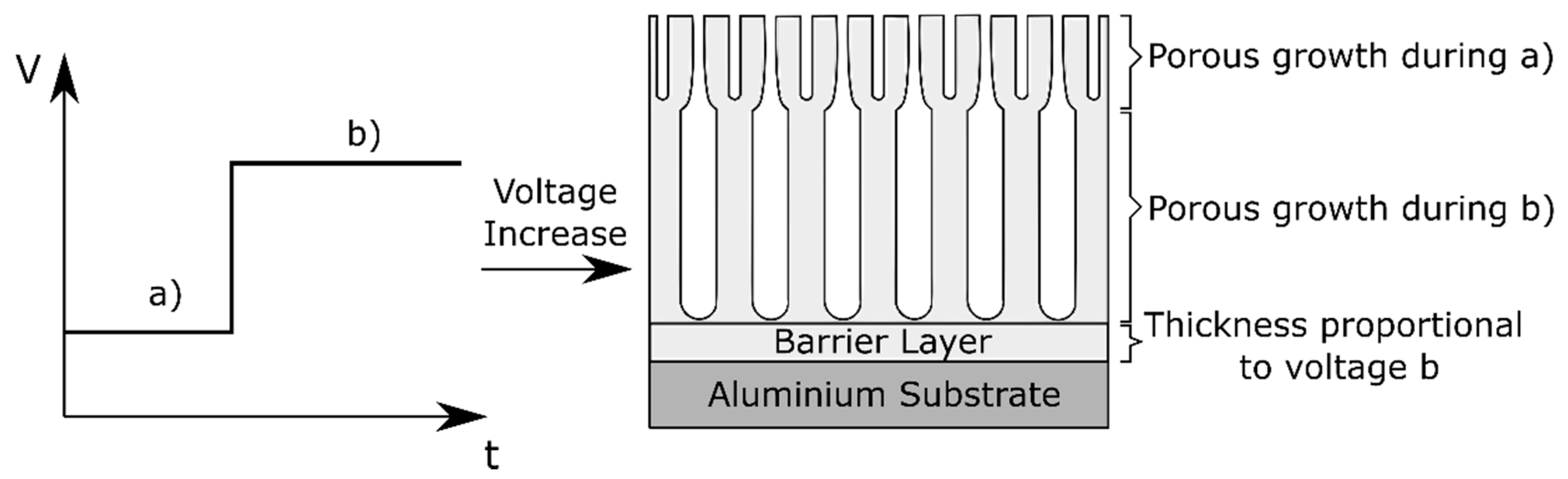
2.4. 2-Step Anodizing: Complex Anodic Layers

Complex anodic oxide layers can also be formed by a two-step anodizing process, in which the first step consists of anodizing in an acidic electrolyte obtaining a porous anodic layer, followed by anodizing in an electrolyte that does not dissolve the film. In this second anodizing step a barrier anodic film is formed underneath the porous one, creating a so called ultra-thick barrier layer. Such films have been investigated by Girginov et al. [77,78] as promising candidate materials for nano-scale dielectric capacitance systems due to its high breakdown voltages.
They fabricated porous anodic films on aluminum using a mixture of two aqueous solutions: 20 wt % H2SO4 and 4.5 wt % (COOH)2 at a constant current density. The second anodizing step was carried out in a neutral aqueous borate electrolyte (ABE). This second step has a two-fold effect: it generated a thick barrier layer below the original porous anodic film and it also partially fills up the pores from the original layer, as schematically illustrated in Figure 6.
To the best of the authors knowledge, there have been no studies on the possible applications of such ultra-thick oxide layers in corrosion protection applications.

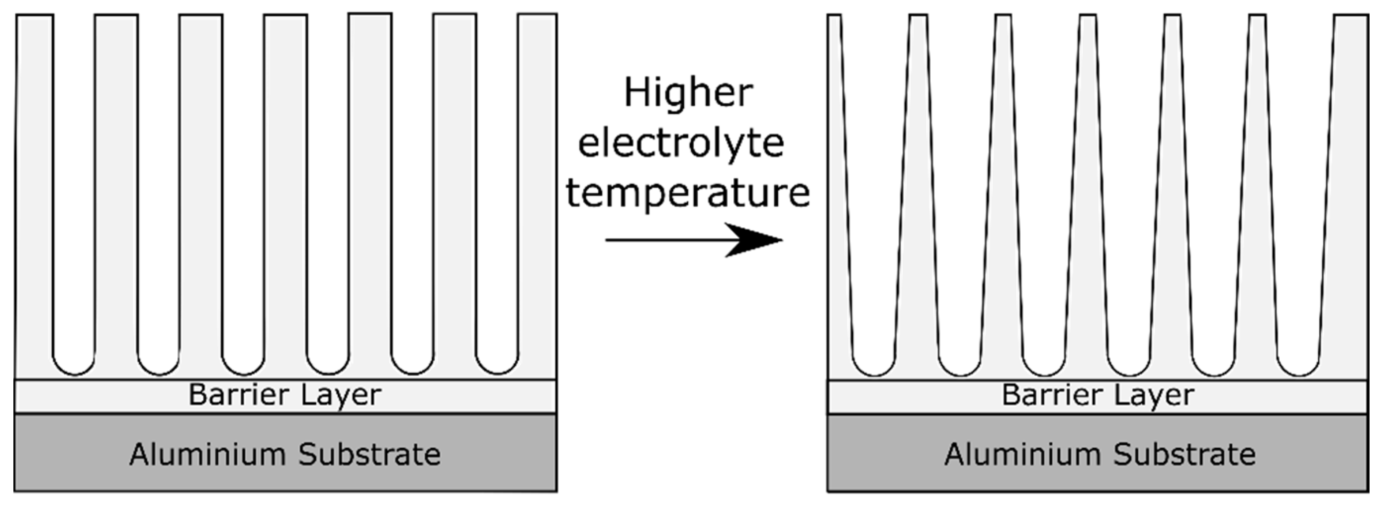
2.5. Effect of the Electrolyte Temperature

During the process of aluminum anodizing, not only the mass transfer needs to be considered, but also the heat transfer [40]. Heat is produced during anodizing mainly by Joule heating due to ionic current passing through the highly resistive oxide layer on the aluminum electrode [40]. Aerts [40] dealt in his PhD thesis with the role of heat transfer and the role of the electrolyte and electrode (i.e., the aluminum part) temperature during anodizing. The electrolyte temperature has an effect on the oxide morphology, visualized in Figure 7. High electrolyte temperatures lead to pore widening close to the oxide/electrolyte interface [79]. This effect is caused by the higher aggressiveness of the electrolyte at higher temperatures, which accelerates the oxide dissolution reaction. The pore widening effect is gradually reduced towards the alloy/oxide interface [79]. In fact, the pore diameter is found to be proportional to the applied formation voltage and independent of the electrolyte temperature in regions close to the barrier layer [79].
The electrolyte temperature also has an influence on the microhardness of the film, which decreases with increasing electrolyte temperature [40]. To assess the significance of the electrode temperature, Aerts [40,79] studied anodizing in a cool electrolyte with a high electrode temperature and vice-versa, keeping the difference of temperature electrolyte-electrode constant. According to his findings, the electrode temperature affects the formation ratio of the oxide layer to a larger extent than the electrolyte temperature.
The impact of the electrolyte temperature on the oxide barrier layer thickness is controversial. In the literature claims can be found reporting barrier layer thinning with an increase of the electrolyte temperature [43,57], while others report no significant changes [54,67,80].

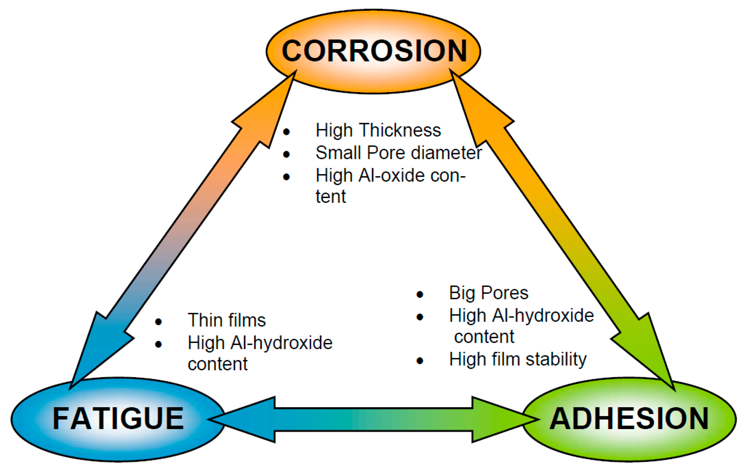
3. Anodic Layer Requirements for Aerospace Applications

The porous anodic layer, as a part of the corrosion protection scheme in aerospace applications, is used as a protective film against corrosion and also as a base for paints and organic coatings loaded with corrosion inhibitors (see Figure 1). This dual function is provided on the one hand by the increased thickness of the oxide compared to the native oxide that increases the corrosion resistance and on the other hand by the thick porous oxide that improves the adhesion to organic coatings, hence also improving the performance of the corrosion protection scheme. Another important aspect is the effect that the anodic oxide layer has on the fatigue properties. Therefore, the three main performance aspects to take into account when assessing anodic layers for aerospace applications are the corrosion protection, the adhesion performance and the effect of the anodic layer on the fatigue properties. These three facets often lead to contradictory anodic layer characteristics, as illustrated in Figure 8.

3.1. Corrosion Protection

Anodizing is an electrolytic passivation process, meaning that the oxide layer formed is relatively inert (except in high and low pH environments) and an electrical insulator. Consequently, no corrosion reactions are sustained. As an example, commercially pure aluminum is heavily corroded after 3.5 years of outdoor exposure in a high salinity environment, with a weight loss of 12 g/m2·year [82]. On the contrary sulfuric acid anodized panels, with a layer thickness of 28 µm and exposed to the same environment, show no signs of corrosion [82]. While the anodic oxide layers formed on pure aluminum substrates are very homogeneous and dense, alloying elements can alter the properties of the layer, reducing the corrosion protection performance. For this reason, there is an interest in understanding the effect of the main alloying elements present in aerospace aluminum alloys, typically from the 2xxx family (Al–Cu) and from the 7xxx family (Al–Zn–Mg–Cu), both as bare alloys as well as cladded with a variety of aluminum alloys.
The effect of alloying elements on the anodic oxide morphology is evident by comparing the anodic layers on bare AA2024-T3 alloy and on AA2024-T3 alloy cladded with a commercially pure aluminum grade (Figure 9). The bare alloy shows a sponge like anodic layer with irregular and lateral porosity, while the cladded alloy exhibits an ordered structure with continuous pores perpendicular to the substrate surface.
In addition, anodic films formed on aluminum alloys are not composed only of pure alumina. Not only because of the incorporation of anions from the electrolyte, but also because alloying elements may incorporate into the anodic layer [46,47,48,83]. This can lead to defects in the oxide layer and to micro-galvanic couplings, both of them detrimental for corrosion protection performance.
The effect of alloying elements on the anodizing behavior and on the anodic layer morphology depends on their nature [45,46,47,48]. Alloying elements can be classified into three categories [41,45]. The first category includes alloying elements with a lower Gibbs’ free energy of oxide formation compared to aluminum oxide (e.g., Mg, Li). The second group consists of alloying elements such as Zn and Cu, which are nobler than aluminum and eventually oxidize during the anodizing process. Finally, the third group is formed by those elements nobler than aluminum that do not undergo an oxidation process (e.g., Au). The most commonly used alloys in the aerospace industry contain magnesium, copper, and zinc as major alloying elements. Hence, special attention is given to the effect of these elements.
Magnesium, being less noble than aluminum, will oxidize even during the initial potential or current ramp, preferentially forming MgO [45]. Since the volume occupied by MgO is smaller than the original volume occupied by elemental magnesium, the resulting oxide film is non-continuous and loose [84]. This leads to void formation at the oxide/metal interface. Aluminum oxide on the contrary, occupies a higher volume compared to elemental aluminum and it is therefore able to fill up the voids of the magnesium oxide, creating a continuous and well-adhering oxide film [45].
The effect of copper and coarse intermetallics on anodizing has been a subject of interest for many researchers. Iglesias Rubianes et al. [70] showed that when copper is present in the aluminum substrate, copper species are incorporated into barrier-type anodic films as units of CuO. In the first step, aluminum is oxidized preferentially at the oxide/alloy interface. The copper present, both in solid solution and in intermetallic phases such as the S-phase (Al2CuMg) and the theta phase (Al2Cu), is not oxidized. Thus, it accumulates beneath the anodic film, leading to a copper-enrichment area. When a certain copper content threshold is reached, copper is oxidized and Al2O3, MgO, and CuO are simultaneously formed.
The effect of alloying elements on the formation of porous anodic oxide layers has been studied using both model and commercially available alloys [47,48]. Model alloys enable studying the contributions of the different phases present in technical alloys separately. They are representative of the matrix and the second phases present in AA2024-T3 and AA7075-T6 alloys. Curioni et al. [48] showed that the effect of copper in solid solution is dependent on the anodizing voltage. At potentials above 6 V (referred to SCE), oxygen evolution occurs in the anodic film. In this process, the mobility of ions in the anodic oxide plays a crucial role. Copper ions migrate outwards (from the substrate alloy to the electrolyte) faster than aluminum ions [48,49,85]. This causes a reduction in the electrical resistivity of the film immediately above the copper-rich areas and a subsequent local increase of potential triggering oxygen evolution [48]. Current oscillations during the first stages of oxidation are a hint of oxygen evolution taking place [48]. Once sufficient pressure is reached, the oxygen bubbles burst and rupture the anodic oxide. The electrolyte can then reach the metal underneath the oxide film, which is subsequently anodized. This leads to the filling of the voids by the formation of a new anodic oxide, but with an altered local morphology [48]. Since the oxygen evolution reaction consumes part of the current but does not contribute to the oxide film formation, the anodizing efficiency of copper-rich aluminum alloys decreases [86]. The rapid migration of copper compared to Al3+ cations would deplete the oxide film of copper compared with the alloy composition [70]. At anodizing potentials between 6 and 3 V (taking the SCE electrode as a reference), the potential is not enough to trigger oxygen evolution; however, copper migration still takes place, forming an enriched copper layer at the oxide/alloy interface [48]. Finally, during anodizing below 3 V (SCE), the preferential oxidation of the surrounding alloy matrix leaves copper-rich regions embedded in the oxide, especially at the pore cell boundaries, as the potential is not enough to trigger the migration of copper ions [48,87]. In fact, anodic layers formed on AA2024 at low potentials have similar morphology to the anodic films formed on commercially pure aluminum [48,87]. Figure 10 shows that, at anodizing voltages below 4 V, the copper-rich second phases (the bright areas in the images) are not oxidized and remain occluded in the oxide.
Similarly, Saenz de Miera et al. [47] studied the potentiodynamic polarization responses of the commercial alloys AA2024-T3 and AA7075-T6 by comparing them to model alloys with similar compositions as the phases present in them. Characteristic current peaks in the potentiodynamic polarization responses of the commercial alloys are associated with Al2CuMg that starts to oxidize at approximately 0 V SCE and Al2Cu and Al7Cu2Fe phases that start to oxidize at 5–6 V SCE. Using TEM imaging they have shown that films on the commercial alloys have a duplex morphology: an external, fine featured region, formed at low potentials, when only the aluminum matrix is oxidized and an inner coarser textured region, formed when the potential is high enough to trigger the oxidation of second phases. This is in line with the results reported by Curioni et al. [48].

3.2. Adhesion

One of the key functions of the anodic layer is to improve the adhesion of the inhibited organic coating to the metallic substrate. Therefore, it is important to understand how adhesion works, how stable the bond is when exposed to moisture and aggressive media and what aspects of the anodic layer are important for adhesion, in order to optimize for adhesion and improve the oxide/organic coating interface stability.
Several theories have been proposed to explain adhesion mechanism: the adsorption, the mechanical, the diffusion or the electrostatic theories. However, no single theory can fully explain adhesion. Each of them seems to be more suitable for some specific applications and substrates than for others [88]. Among them, the adsorption and the mechanical theories are generally recognized to be the most suitable theories to explain adhesion between metal oxides and polymers [16,88].
The adsorption theory explains adhesion at a microscopic level. According to this theory, adhesion occurs when a molecular or atomic interaction between the oxide and the polymer takes place. Thus, for this molecular interaction to happen, there must be intimate contact between the polymer (in this case the organic coating) and the oxide. However, intimate contact is not enough for adhesion to take place and molecular interactions involving both physical and chemical bonding must occur [89]. Van der Waals forces—in particular London, Keesom, and Deebye interactions—are responsible for physical bonding [89]. These interactions account for the forces between permanent and induced dipoles. Even though these bonds are weak in comparison to chemical bonding, they take place between any two molecules in contact and consequently contribute to all adhesive bonds [88]. Conversely, the formation of a chemical bond depends on the ability to form a covalent or ionic bond between the oxide and the polymer. Chemical bonds, in particular covalent bonds, are the strongest and most stable bonds that can contribute to adhesive bonding. In fact, adhesion promotion by coupling agents such as organosilanes has been reported to be partially caused by the ability of these coupling agents to form covalent bonds across the interface [90].
A third group of interactions taken into account in the adsorption theory are acid–base interactions. This was first proposed by Fowkes [91] and are considered to play the main role in the adhesive bond formation within the adsorption theory [92]. Acid–base interactions occur between an interfacial donor and acceptor of an electron pair. Of particular interest among the acid–base interactions are the so-called hydrogen bonds. They have been identified as the most important contribution to adhesion between aluminum oxide and polymeric resins, in particular epoxy resins [83,92]. Hydrogen bonds are thought to form between the hydroxyl groups of the epoxy resin and the available hydroxyl groups on the aluminum oxide surface. Abrahami et al. [83,93,94] have shown that indeed the adhesive bonding strength of feature-less oxides and epoxy resins correlates with the amount of hydroxyl groups available at the oxide surface. An extract of their results can be seen in Figure 11.
The mechanical adhesion theory advocates that mechanical interlocking at a macroscopic level governs the adhesive bonding strength. The interface is herein seen as a composite material formed by the adhesive penetrating cavities, pores or rough features of the substrate and the substrate surface [95]. While it is generally recognized that mechanical interlocking improves adhesion, there is debate within the research community on whether it is indeed the governing factor. The fact that good adhesion can also be achieved by featureless surfaces [83,93,94] indicates that chemical interaction must also be taken into account. Some researchers even argue that the improved adhesion strength that has been traditionally explained by mechanical interactions can instead be attributed to an increase in the contact area between the oxide and the polymer, consequently leading to an increase in the interfacial atomic or molecular interactions [96]. In the particular case of porous anodic layers, Abrahami et al. [97] found that morphology (pore size and surface roughness) has an effect in both initial and wet peel strength of anodic oxide layers formed on aluminum substrates with an epoxy resin.
For aerospace applications, it is vital to take into account not only the initial adhesive bond strength but also the stability of the interface as good adhesion needs to be retained for long periods and under aggressive environments. Maege et al. [98] consider that delamination takes place as a result of electrochemical reactions occurring at the oxide/coating interface. The ingress of water, oxygen, or aggressive ions such as chlorides is governing delamination at a molecular level. Water ingress at the interface can displace the adhesive or modify the adhesion properties leading to failure of the bond. The stability of the film towards water ingress has been found to be highly dependent on the surface chemistry of the oxide [93]. Corrosion is also to some extent related to the adhesion of the organic coating to the anodic layer. When good adhesion between the organic coating and the oxide occurs, water, and/or aggressive ions cannot easily ingress the interface and propagate along it and, consequently, corrosion is restrained [93,97,99]. All in all, the stability of the chemical and physical interfacial bonding, as well as the number of interactions at the interface, play a critical role in environmental-assisted delamination process [89,98,100].
Considering the importance of the interface stability, an option to further improve adhesion are pre- and post-treatments with adhesion promoters. Adhesion promoters are able to form stable covalent bonds both with the metallic oxide substrate and the polymeric resin of the coating. Thus, it improves the stability of the interface against chemical attack and moisture ingress. Post-treatments by immersion in solutions containing silanes [90,101,102] and phosphonic acid [98,103,104,105] have been shown to improve the adhesion and stability of a variety of coating chemistries to anodic oxides. Recently, a pre-treatment with diazonium-salts bearing an amine group has been proposed [38]. The diazonium salts graft spontaneously to the bare metal in an acidic solution before anodizing, and this layer is retained after the anodizing process [38]. While adhesion promoters are an interesting option to enhance coating adhesion, it has to be taken into account that from an industrial perspective they also increase the complexity of the process by adding additional steps. Moreover, the potential negative impacts on storage and transport logistics prior to painting should be carefully analyzed.
The evidence found in literature confirms that surface properties of the oxide layer are extremely important to ensure good adhesion of organic coatings. The surface chemical composition, its acid–base character, the oxide morphology and the surface roughness have to be considered when aiming for good and durable adhesion.

3.3. Fatigue

It has been broadly reported that anodic oxide layers are detrimental to the fatigue properties of the underlying aluminum alloy [106,107,108,109,110,111]. The brittleness of the oxide film, typical of ceramic-like materials, compared to the substrate, makes the oxide film prone to crack nucleation. The fatigue life is formed by two stages: the crack initiation period and the crack propagation period. The effect of the higher susceptibility to crack initiation by the presence of the anodic layer on fatigue properties can be understood from the fact that the crack initiation period accounts for up to 90% of the total fatigue life [106].
The thicker the oxide film is, the highest is the loss of fatigue strength. A thicker oxide film provides larger areas for crack growth and coalescence, as well as a higher probability of oxide defects [108,112]. Thus, the anodic layer thickness is limited by the fatigue properties. For example, Lonyuk et al. [109] report a 46% reduction in fatigue limit for 10 µm anodic films formed in a sulfuric acid electrolyte on 7475-T6. For 60 µm thick films, the fatigue limit is reduced by 75%.
Besides the anodic oxide film thickness, the oxide morphology plays an important role in the fatigue properties reduction. The oxide morphology varies depending on the pre-treatments, as well as on the electrolyte and the parameters used in the anodizing process. The pre-treatment steps, in particular alkaline etching and acidic pickling (introduced in Section 5.1.2 and Section 5.1.3), already have a detrimental effect on fatigue life. During these steps, the dissolution and oxidation of intermetallic phases leads to the formation of pits that serve as crack nucleation areas [112,113]. In addition, chromic acid anodizing (CAA) and tartaric sulfuric acid anodizing (TSA) have been shown to be less deleterious for fatigue properties than sulfuric acid anodizing (SAA) [112]. This can be seen in Figure 12.
Anodic oxide films are not only prone to crack nucleation, but also an increase on the crack propagation rate has been reported. Two concurring mechanisms are proposed by Cree and Weidmann [106]: on the one hand the appearance of micro-cracks in the vicinity of the growing fatigue crack tip, which alter the growth characteristics by providing a path of least resistance. On the other hand, a lower plasticity of the oxide film compared to the underlying substrate, which reduces the closure of the crack. The crack closure effect is further reduced by the residual tensile stress generated during anodizing, which increases the effective tensile stress under tensile cyclic stress loads. Shot-peening prior to anodizing improves the fatigue life, as it creates a compressive residual stress field in the surface-near area, which is retained even after anodizing, which delays crack nucleation and growth [108,114,115].

4. Substitution of the Chromic Acid Anodizing Process

For decades chromic acid has been used as anodizing electrolyte for aerospace applications. The morphological and chemical properties of anodic oxide layers formed in chromic acid constitute a very good balance between corrosion protection, adhesion, and fatigue properties.
The nano-rough porous and easily wettable oxide structure formed during chromic acid anodizing (CAA) is beneficial for adhesion both of structural adhesives as well as inhibitor-loaded primers [116]. Additionally, the relatively thick (3–4 µm on relevant aerospace bare and clad alloys) and amorphous oxide provides barrier corrosion protection and resistance to attack by moisture [116,117]. Although the CAA oxides have been found to be almost anion free, with chromium content ranging from 0.1–0.3 wt % [83,117], the incorporation of chromates to the film contributes to a certain degree of active corrosion inhibition both at anodic and cathodic corrosion sites [46]. In addition, the incorporated chromate anions restrict chlorine adsorption by reducing the zeta potential of the oxide film, further contributing to the resistance of the layer in aggressive environments [46]. As previously discussed, the second phases present in aerospace alloys (especially those rich in copper or iron) cause disruption in the formation process and morphology of the anodic layer. The ability of the electrolyte to oxidize these second phases is important to ensure sufficient anti-corrosion properties, as second phase oxidation reduces the number of potential cathodic sites within the anodic oxide or immediately below it [47]. Chromic acid electrolyte is able to oxidize second phases and this capability should be maintained by a potential health and environmentally friendly substitute electrolyte. Another important aspect is that the formed oxide is also found to be relatively ductile [117], being therefore less detrimental than others (e.g., oxalic or sulfuric acid anodizing) for fatigue properties.
Taking into account all of the above-mentioned properties, alternative processes to replace CAA must lead to the formation of an anodic layer with the right corrosion protection-adhesion-fatigue balance (see Figure 8) [118]. Furthermore, in an industrial environment, a replacement anodizing process is not a stand-alone process but rather a step within a more complex procedure. Hence, CAA-replacements must be compatible with existing installations, the process parameters (process time, voltage, temperature) must be in the same order of magnitude as for CAA, it must be compatible with all the relevant aluminum alloys and the anodic oxide must be able to cope with logistics constraints, as for example a short current-free period in the anodizing bath or being exposed to the atmosphere for some days before painting operations.
The most popular candidate electrolytes that have been so far studied to substitute chromic acid can be clustered in two classes: the processes using phosphoric acid based and alkaline electrolytes that provide good adhesion properties but poor corrosion protection performance due to the open porous morphology of the anodic oxide and the inhibition of aluminum hydroxide precipitation in a subsequent sealing step because of phosphate incorporation [42,119]. The second class are processes using sulfuric acid-based electrolytes that provide good corrosion protection but reduced adhesion due to the dense porous morphology of the oxide [15,45,46,120,121,122,123]. While CAA was a suitable process both for bonding and corrosion protection applications, two processes have been introduced for its replacement: phosphoric acid anodizing (PAA) as well as phosphoric-sulfuric acid anodizing (PSA) for structural bonding applications and sulfuric acid anodizing (SAA) or mixed sulfuric acid—organic acid electrolytes (e.g., tartaric-sulfuric acid anodizing TSA) for corrosion protection applications. This review will further on focus on mixed sulfuric acid-organic acid anodizing processes. The interested reader is encouraged to read the review by Abrahami et al. [16] as well as the review by Critchlow et al. [116] that focus on Cr(VI)-free anodizing for structural bonding applications.
Sulfuric-acid anodizing (SAA) generally leads to a thick and dense sulfate-containing oxide layer. This process has long been used for aesthetic, wear resistance (hard anodizing) and corrosion protection purposes. However, its low porosity [120], detrimental for adhesion, and its greater thickness [123], detrimental for fatigue, make it unsuitable as a CAA alternative as a pre-treatment for aerospace painting and bonding applications. However, these drawbacks can be overcome by the addition of weak organic acids. The association of a weak organic acid with a strong mineral acid has received the name of mixed-acid anodizing. While most organic acids form barrier anodic oxide layers when used as sole anodizing electrolytes, porous anodic oxide layers are formed when they are combined with sulfuric acid [34]. The addition of organic acids to sulfuric acid electrolytes has been studied for different purposes [15,31,32,33,34,45,83,124,125,126,127]. In particular, Vignoli et al. [34] studied the influence that adding different carboxylic acids to sulfuric acid has on the morphology, composition, and corrosion behavior of anodic oxide films on AA2024 alloy and compared their performance to CAA oxide films. They investigated the addition of oxalic, malic, malonic, tartaric, and citric acids to a sulfuric acid electrolyte and found out that the addition of tartaric (TSA) and malic (MSA) acids delayed the stable pit growth in comparison to using an electrolyte containing only sulfuric acid. The improved corrosion protection behavior of the films formed in TSA and MSA electrolytes may be due to the decreased dissolution of copper-rich precipitates, which translates into smaller and less numerous voids and defects in the oxide film. Still, CAA outperformed all the tested alternatives. Among the mixed sulfuric-acid based electrolytes, tartaric sulfuric acid anodizing has been widely reported in the literature as an alternative to CAA for corrosion protection applications. Due to its relevancy, TSA is thoroughly discussed in the following section.

4.1. Tartaric Sulfuric Acid Anodizing (TSA)

Tartaric acid is an organic acid found in wine and some fruits, but it can also be synthesized [128]. In the early 2000s, when TSA was industrially introduced [129], it was generally recognized that its addition to a sulfuric acid electrolyte contributed to the improvement of the corrosion resistance of the anodic film on aluminum alloys. However, the precise mechanism was not clear. Consequently, the function of tartaric acid has been the subject of numerous studies [15,26,32,34,46,70,130,131,132,133,134,135,136]. Iglesias-Rubianes et al. [70] report that the addition of tartaric acid reduces the steady-state current during film growth at constant voltage by up to 20%. This was further supported by Curioni et al. [15]. They found out that the addition of tartaric acid leads to a general reduction of the current density during anodizing of both pure aluminum and AA2024-T3 alloy. Ma et al. [137] also studied the effect of adding different tartaric acid concentrations to a 0.46 M sulfuric acid solution on the anodic oxide growth rate. They report that the film growth rate increased with increasing tartaric acid concentration until it reached a maximum at 0.53 M tartaric acid addition. This coincides with a minimum in steady-state current density [137]. A remarkable change in the current evolution during anodizing in the presence of tartaric acid was the suppression of the initial current peak [15], related to the dissolution of S-phase particles [46,47,48]. This indicates that tartaric acid suppresses preferential dissolution of this phase at potentials close to the OCP [15]. However, at higher potentials, tartaric acid seems to have no effect. This means that the oxygen evolution and, therefore, the film disruptions at higher potentials are not altered [15].
The general steady-state current reduction during anodizing in TSA could be related to the incorporation of tartaric acid into the film, since this would cause an increase in the resistance of the oxide layer. To investigate this Curioni et al. [15] carried out a second anodizing step after TSA or SAA anodizing. In this second anodizing step a barrier oxide layer is grown both at the alloy/oxide interface and at the oxide/electrolyte interface. In this way the oxide film formed during the first anodizing step is embedded between the newly formed barrier oxides. If there is indeed a difference between the electrical properties of TSA- and SAA-oxide layers, a difference in the voltage response during the second anodizing step is expected. However, no significant difference in the voltage response occurred.
Iglesias-Rubianes et al. [70] hinted that the addition of tartaric acid to sulfuric acid could influence the field assisted dissolution. This aspect was also studied by Curioni et al. [15]. A barrier anodic layer was immersed in the TSA electrolyte and the degradation of the anodic layer was monitored by electrochemical impedance spectroscopy. Additionally, oxide dissolution was monitored. Both EIS results and thickness reduction rates showed that the presence of tartaric acid in the electrolyte reduces the rate of oxide dissolution.
In terms of performance, it has been observed that the addition of tartaric acid to sulfuric acid leads to an enhanced corrosion protection of the anodic layers [15,34,45,131,132,137]. For example Ma et al. [137] carried out neutral salt spray tests of Al–Li substrates anodized in sulfuric acid solutions containing various tartaric acid concentrations. They found that the corrosion protection performance of the films increased with increasing tartaric acid concentration. One possible explanation for the enhanced corrosion protection may be the buffering capacity of tartaric acid and its derivate species. It has been proven that they have buffering properties at concentrations as low as 100 ppm in a pH range between 4.5 and 2.75 [15]. However, if this buffering abilities are responsible for the improvement in corrosion protection, a significant amount of tartrate species should be incorporated, absorbed or present as remnants in the porous oxide film [15]. It is to this day unclear whether this is indeed the case.
One hypothesis is that during the anodizing process, tartaric acid reacts with aluminum cations present inside the pores, close to the oxide/electrolyte interface, forming aluminum tartrate. Aluminum tartrates are highly soluble in acidic environment; however, its solubility drastically reduces in water. Hence, the sudden pH increase caused by subsequent rinsing in deionized water would favor the precipitation of aluminum tartrate into the pores [15,132]. The pores would then act as aluminum tartrate reservoirs. Aluminum tartrate could be re-dissolved at a later point in time, when in contact with an aggressive environment, creating a buffer solution, hindering local alkalinization or acidification and subsequently enhancing corrosion protection capabilities [15].
The presence of tartrates can also affect the precipitation of aluminum hydroxide during sealing processes. The precipitation of aluminum hydroxide is favored by the chemical conditions, especially by the pH, that are generated when not only sulfate salts but also tartrates salts are hydrolyzed [131]. Arenas et al. [132] studied the corrosion properties of hydrothermally sealed anodized specimens in TSA and SAA by means of EIS. The results show better corrosion resistance for sealed specimens anodized in TSA than in SAA. They propose that tartaric acid traces within the pores favored sealing. Similarly to the hypothesis of Curioni et al. [15], they propose that the higher pH value of the sealing bath allows residual tartaric acid to dissociate forming tartrate ions. These tartrate ions could form chelate complexes with cations available in the oxide film, specifically with Cu2+. The chelating of copper would improve the corrosion resistance of the film by increasing its homogeneity and by reducing the active corrosion sites within the film by preventing copper redeposition. To our knowledge, no experimental proof of this mechanism has been reported.
To elucidate whether tartaric acid or its derivatives are in some form present in the anodic film, Garcia Rubio [45] performed glow discharge optical emission spectroscopy (GDOES) measurements of anodic films formed in tartaric sulfuric acid, showing a correlation between the carbon and the hydrogen signal. The carbon, hydrogen, and sulfur signals peak at the same sputtering time. This suggests that carbohydrates, most likely tartrates, migrate towards the oxide/metal interface at a rate similar to the sulfates migration speed. As far as we know, no further investigation on the incorporation and possible further precipitation of tartrates has been carried out.
While TSA has been successfully introduced as a CAA alternative at an industrial level and the published research has elucidated many aspects of the role that tartaric acid plays both during and after anodizing, some mechanistic questions remain open.

5. Anodizing as a Step in a Process

Anodizing is not a stand-alone process, but rather a step in a bigger and more complex process. Other processes that take place before and after anodizing help to create the corrosion protection system. The following sections discuss these pre- and post-treatments, highlighting their interdependence with the anodizing step.

5.1. Pre-Treatment

Pre-treatment steps prepare the substrate surface for anodizing. Typically, a degreasing, an alkaline etching, and an acidic pickling step are carried out. These steps are discussed in the following sections and their effect on the substrate are schematically represented in Figure 13.

5.1.1. Degreasing

Degreasing is the first pre-treatment step and its objective is to remove any contamination, especially oils and lubricants, used during metallurgical processing [117]. Degreasing is performed to allow full wetting, ensuring that the following processing steps will work evenly across the substrate surface [42]. For this step, an alkaline cleaner is typically used in the aerospace industry. Aluminum is readily dissolved in alkaline solutions, which means that alkaline cleaners for aluminum must work at comparatively low alkalinity and must be inhibited to prevent attack of the metal during the degreasing step [53]. Immediately after degreasing, the parts are rinsed in deionized water baths or under running deionized water. If the cleaner is not immediately rinsed and it dries on the metal surface, it will be very difficult to remove at a later stage [45]. Agitation of the rinse is also useful to ensure the complete removal of the alkaline cleaner.

5.1.2. Alkaline Etching

The surface of the aluminum substrate in its ‘as-received’ state has a higher susceptibility to corrosion [138]. Compositional changes, grain refinement, precipitation of dispersoids and embedding of the surface oxide and broken intermetallic in the matrix all take place during metallurgical processing [138,139,140,141]. This modified layer constitutes the so called near-surface deformed layer (NSDL) [140] or grain refined surface layer (GRSL) [138]. Near-surface deformed layers are formed when the alloy surface and near-surface regions experience a high level of shear deformation. This results in significant grain refinements, and therefore near-surface deformed layers have a microstructure that is different from the underlying bulk alloy [138,139,140,141]. This different microstructure is even retained after annealing processes [140]. Zhou et al. [140] describe two types of near-surface deformed layers, shown in Figure 14: Type A layers are characterized by fine grains with oxide particles located at the grain boundaries and Type B layers also consisting of fine grains but in this case no oxide particles are present at the grain boundaries. Near-surface deformed layers are removed by the alkaline etching step, which typically consists of immersion in an aqueous sodium hydroxide solution [53]. Although the etching step is technically a simple process, many competing reactions can occur in practice and the presence and level of bath additives, the bath temperature and the dissolved aluminum content make this process very complicated [53]. The mechanistic explanation of how all these parameters affect the alkaline etching process is out of the scope of this review. The interested reader can find comprehensive information elsewhere [54,117,130,141,142].
Besides the removal of the NSDL, alkaline etching has an effect on the chemical composition of the substrate surface. To quantify this effect, Moffitt et al. [143] performed an XPS study on alkaline etched 2024 and 7075 alloys. They found out that alkaline etching removes the Mg-enriched surface layer from the as-received panel. In addition, an enrichment of alloying elements, such as copper, takes place at the substrate surface. This leads to a condition in which the material immediately beneath, and sometimes even penetrating through the oxide layer is prone to corrosion, as these copper rich areas serve as cathodic sites [144,145]. Moreover, Moffit et al. [143] report that combinations of different co-enrichments (e.g., Zn–Cu) may amplify the risk of corrosion beneath the protective oxide.
During alkaline etching of copper-rich aluminum alloys smut is deposited on the surface of the part. The smut is formed by alloying elements insoluble in the alkaline media, in the case of typical aerospace alloys mainly copper, iron, and silicon [45]. Since this smut is not soluble in the alkaline media, it needs to be removed in a subsequent step.

5.1.3. Acidic Pickling

Both pickling and etching modify the surface of the as received substrate by chemical dissolution. The difference between pickling and etching is not well defined, although pickling is generally considered as a slightly milder process [42]. The aim of the acidic pickling is to act as a desmutting agent by removing the insoluble products generated during the previous alkaline etching process [141].
The acidic pickling process usually follows a two-step reaction mechanism, one being the alumina formation reaction and the other one the alumina dissolution reaction. The alumina formation reaction rate is typically faster than the rate of alumina dissolution. This results in the formation of a thin oxide layer on the surface [42]. The morphology of this thin oxide depends on the composition of the acidic pickling solution. It has been observed that acidic pickling solutions containing fluorides lead to a flat and smooth surface, while those being fluoride free cause a thin porous oxide on the surface [146]. Fluoride ions are often added to reduce the treatment time and/or the treatment temperature. They promote the aluminum oxide dissolution reaction due to their strong affinity to aluminum ions [147]. In the presence of fluoride, the aluminum oxide dissolution rate may offset the alumina formation rate, leading to a flat, featureless surface.
Acidic pickling has traditionally been based on mixtures of chromic and sulfuric acid, sometimes with addition of fluorides [148,149]. However, due to the toxicity of hexavalent chromium, and the environmental concern related to the use of fluoride-containing products [13], new formulations have been recently developed. Among those, the most promising ones consist of a mixture of sulfuric acid, nitric acid, and ferric sulfate. Garcia Rubio [45] describes the action of each component of the mixture: the sulfuric acid reacts with tin, zinc, and copper and it produces the corresponding salt, water, and sulfur dioxide [45]. Nitric acid is generally reduced in the acidic environment. Typically in this reduction reaction, a mixture of nitrogen oxides, nitrates and other alloying-element-dependent reaction products are formed [44]. According to Moffitt et al. [143], nitric acid de-smutting may be a practical solution to remove large deposits of copper compounds in contact with the bulk alloy surface through the oxide and possibly on top of the oxide. It appears, however, that it does not eliminate thin enrichments beneath an established oxide. Nitric acid acts as an oxidizer when reacting with magnesium. In this case the corresponding magnesium salt is formed, and hydrogen evolution takes place [45]. Finally, ferric sulfate also acts as an oxidizing agent [45].
An alternative to the classical acidic pickling is anodic pickling. While acidic pickling is a purely chemical process, anodic pickling is an electrochemical process, in which the aluminum part is the anode. During anodic pickling, oxygen evolves on the metal surface, which scrubs the surface and cleans the surface from scale and smut [150]. Farrell and Horner [150] propose that anodic pickling in a sulfuric acid solution could be used as a stand-alone pre-treatment step, since degreasing, pickling, and de-smutting functions are all provided by the anodic pickling process. However, metal loss and even pitting can occur during the anodic pickling process [150]. While metal loss can be reduced by adjusting the sulfuric acid concentration, this adjustment can lead to smut formation [150], reducing the advantages of anodic pickling as a stand-alone pre-treatment process. Patents concerning the anodic pickling process were granted to Fokker in the late 1970s and early 1980s, as fully chromate free processes. The first Fokker patent [151] describes a pickling method that gets rid of the native oxide layers and serves as a preparation step prior to adhesive bonding or prior to anodizing. In the patented process, the aluminum part is placed as an anode in a sulfuric acid bath, connected to a cathode placed in the same bath and a constant voltage is imposed during the pickling process. Subsequent patents from Fokker [152,153] consist of modifications of the process described in the first one [151]. The objective of the modifications is to get rid of the anodic control voltage. One of the patents [152] connects the aluminum parts as anode by a short-circuit connection to a carbon cathode placed in the same sulfuric acid bath. Sufficient electric current flows through the short-circuit connection to initiate electrochemical dissolution at the surface of the aluminum anode. Finally, the third patent [153] describes the immersion of aluminum parts into a sulfuric acid bath containing carbon particles in suspension. The carbon particles will form small electric cells with aluminum parts at their places of contact and will initiate electrochemical dissolution at these regions. No further references to these patented or other similar processes have been found in the literature.
The surface morphology and chemistry resulting from the acidic pickling step is of importance, as it will be retained to some extent after anodizing. This highlights the importance of pre-treatments in general and of the acidic pickling in particular, when studying and assessing anodizing processes and the performance of the resulting anodic oxide layers.

5.2. Post-Treatments

In this context, post-treatment is a term used to refer to all subsequent steps that take place after anodizing. These include sealing and/or painting. The next section focusses on the sealing post-treatment. Primers, paints, and painting operations are out of the scope of this review.

5.2.1. Sealing

Some anodized parts are intended for use without being painted. To improve its corrosion protection, the open porous oxide that was created during the anodizing process serves as a basis for a sealing step used to fill up and/or close the pores. During a hydro-thermal sealing the anodized part is immersed in boiling water with or without additives to further enhance corrosion protection. Three steps take place during immersion: first the aluminum oxide dissolves into the hot water, then a gel-like aluminum hydroxide is deposited on the surface and finally pseudoboehmite is formed by condensation of the gel [31]. As previously mentioned, phosphates have the ability to suppress the alumina hydration mechanism [53]. This makes anodic layers formed in phosphoric acid and phosphoric-sulfuric acid electrolytes not sealable.
Hot water sealing improves the corrosion resistance of the anodic layer through an improvement of the barrier effect by closing of the pores [147]. If instead of pure water, a sealing electrolyte containing corrosion inhibiting species is used, the precipitated products act as reservoirs for corrosion inhibitors, further improving the corrosion resistance [147]. Typically, hexavalent-chromium-based sealing electrolytes have been used. Therefore, similarly to the anodizing step, there is a need for substitution that comply with the new environmental and health regulations. Nickel-fluoride and nickel-acetate sealing processes have been considered good alternatives in the past; however nickel, as hexavalent chromium, is also subject to environmental regulations. In recent years, different environmentally-friendly corrosion inhibitors for sealing have been the subject of study. Vanadium, molybdate, and a combination of both have been successfully incorporated into sealed anodic layers [22]. Nitrogen-rich compounds such as azoles and tetrazines, which have the ability to bind to chloride-ions as well as to bind and stabilize copper species, have also been studied as possible inhibitors to be incorporated into sealed anodic layers [24]. However, the stability and irreversibility of the protection provided by these nitrogen-rich inhibitors has recently been questioned [154]. The incorporation of Ce(III) compounds as inhibitor has also been studied [147]. The development of a Cr(VI)-free sealing process is ongoing. Several concepts, including the ones mentioned above but also others, are being considered and up to now none of them has imposed itself as the new industrial standard. The reader is referred to the recent systematic review published by Ofoegbu et al. [155] for further detailed information.

6. Conclusions

High strength aluminum alloys are widely used in aerospace applications, mainly due to their outstanding weight-specific mechanical properties. However, the alloying elements used for strengthening the aluminum matrix make the resulting alloy susceptible to corrosion. Hence, a durable and reliable corrosion protection system is needed. Anodic oxide layers play an essential role in these a protection systems. They must provide sufficient corrosion protection to prevent contact between electrolytes (such as moisture, hydraulic fluid, etc.) and the underlying metal, as well as improving the adhesion to organic coatings and paints, while at the same time not compromising the fatigue properties of the metal component.
To achieve this goal, it is important to understand how anodizing works. Its complexity has been reviewed, discussing the role of process parameters (e.g., voltage and temperature), the nature of the electrolyte or the nature of the substrate, but also the process steps carried out before and after anodizing. This highlights the importance of considering anodizing not as a stand-alone process, but as a step in a larger and more complex process.
Taking into account the above-mentioned complexity, it is clear how challenging it is to substitute the well-established chromic acid anodizing (CAA) process. In the past, CAA was used both for aerospace structural bonding and corrosion protection applications, due to a good balance between corrosion protection, adhesion, and fatigue properties of the resulting oxide layer. Many efforts have been done in the past decades to search for alternatives to hexavalent chromium in the different processes where it is used. So far, one type of process is not able to substitute for the entire range of applications. For anodizing applications, phosphoric acid-based processes (PSA; PAA) have been established for structural bonding applications, whereas tartaric-sulfuric acid anodizing (TSA) has been introduced as an alternative Cr-(IV)-free process for corrosion protection applications. While TSA has been widely studied, questions about the role of tartaric acid and its derivatives during anodizing and in service remain open.

Author Contributions

Writing—original draft preparation, M.P.M.-V.; Writing—review and editing, S.T.A., H.T., T.H. and M.B.; Supervision, S.T.A., H.T., T.H. and M.B. All authors have read and agreed to the published version of the manuscript.

Funding

This research was funded by Airbus Central Research and Technology.

Conflicts of Interest

The authors declare no conflict of interest.

References and Notes

  1. Budinski, K.G.; Budinski, M.K. Engineering Materials: Properties and Selection; Prentice Hall: Upper Saddle River, NJ, USA, 2010; ISBN 978-0-13-712842-6. [Google Scholar]
  2. Gialanella, S.; Malandruccolo, A. Aerospace Alloys; Topics in Mining, Metallurgy and Materials Engineering; Springer International Publishing: Basel, Switzerland, 2019; ISBN 978-3-030-24440-8. [Google Scholar]
  3. Anthony, E. Hughes High Strength Al-Alloys: Microstructure, Corrosion and Principles of Protection. In Recent Trends in Processing and Degradation of Aluminum Alloys; Birbilis, N., Ed.; IntechOpen: Rijeka, Croatia, 2011; p. 223, Chapter 10. [Google Scholar]
  4. Boag, A.; Hughes, A.E.; Wilson, N.; Torpy, A.; MacRae, C.; Glenn, M.; Muster, T. How complex is the microstructure of AA2024-T3? Corros. Sci. 2009, 51, 1565–1568. [Google Scholar] [CrossRef]
  5. Becker, M. Chromate-free chemical conversion coatings for aluminum alloys. Corros. Rev. 2019, 37, 321–342. [Google Scholar] [CrossRef]
  6. Matykina, E.; Arrabal, R.; Mohedano, M.; Mingo, B.; Gonzalez, J.; Pardo, A.; Merino, M.C. Recent advances in energy efficient PEO processing of aluminum alloys. Trans. Nonferrous Met. Soc. China 2017, 27, 1439–1454. [Google Scholar] [CrossRef]
  7. Del Olmo, R.; Mohedano, M.; Visser, P.; Matykina, E.; Arrabal, R. Flash-PEO coatings loaded with corrosion inhibitors on AA2024. Surf. Coat. Technol. 2020, 126317. [Google Scholar] [CrossRef]
  8. Hagans, P.L.; Haas, C.M. Chromate Conversion Coatings. In Surface Engineering; Cotell, C.M., Sprague, J.A., Smidt, F.A., Jr., Eds.; ASM International: Cleveland, OH, USA, 1994; Volume 5, pp. 405–411. ISBN 978-1-62708-170-2. [Google Scholar]
  9. Simchen, F.; Sieber, M.; Kopp, A.; Lampke, T. Introduction to plasma electrolytic oxidation—An overview of the process and applications. Coatings 2020, 10, 628. [Google Scholar]
  10. McCafferty, E. Introduction to Corrosion Science; Springer: New York, NY, USA, 2010; ISBN 978-1-4419-0455-3. [Google Scholar]
  11. Benavides, S. Corrosion Control in the Aerospace Industry; Woodhead Publishing Series in Metals and Surface Engineering; Elsevier Science: Amsterdam, The Netherlands, 2009; ISBN 978-1-84569-553-8. [Google Scholar]
  12. United States Department of Labor OSHA, Toxic and Hazardous Substances in Occupational Exposure to Hexavalent Chromium. Regulatory standard 29 CFR 1910.1026 and 29 CFR 1926.1126 Federal Register Number 71:10099-10385 29 2006.
  13. Regulation (EC) No 1907/2006 of the European Parliament and of the Council of 18 December 2006 concerning the Registration, Evaluation, Authorisation and Restriction of Chemicals (REACH), establishing a European Chemicals Agency, amending Directive 1999/45/EC and repealing Council Regulation (EEC) No 793/93 and Commission Regulation (EC) No 1488/94 as well as Council Directive 76/769/EEC and Commission Directives 91/155/EEC, 93/67/EEC, 93/105/EC and 2000/21/EC 2006. Official journal L396, pp. 1–849.
  14. Garcia Rubio, M.; Ocon, P.; Climent-Font, A.; Smith, R.W.; Curioni, M.; Thompson, G.; Skeldon, P.; Lavia, A.; Garcia, I. Influence of molybdate species on the tartaric acid/sulfuric acid anodic films grown on AA2024 T3 aerospace alloy. Corros. Sci. 2009, 51, 2034–2042. [Google Scholar] [CrossRef]
  15. Curioni, M.; Skeldon, P.; Koroleva, E.; Thompson, G.E.; Ferguson, J. Role of Tartaric Acid on the Anodizing and Corrosion Behavior of AA 2024 T3 Aluminum Alloy. J. Electrochem. Soc. 2009, 156, C147–C153. [Google Scholar] [CrossRef]
  16. Abrahami, S.T.; de Kok, J.M.M.; Terryn, H.; Mol, J.M.C. Towards Cr(VI)-free anodization of aluminum alloys for aerospace adhesive bonding applications: A review. Front. Chem. Sci. Eng. 2017, 11, 465–482. [Google Scholar] [CrossRef]
  17. Visser, P.; Gonzalez-Garcia, Y.; Mol, J.M.C.; Terryn, H. Mechanism of Passive Layer Formation on AA2024-T3 from Alkaline Lithium Carbonate Solutions in the Presence of Sodium Chloride. J. Electrochem. Soc. 2018, 165, C60–C70. [Google Scholar] [CrossRef] [Green Version]
  18. Moutarlier, V.; Gigandet, M.P.; Normand, B.; Pagetti, J. EIS characterisation of anodic films formed on 2024 aluminum alloy, in sulfuric acid containing molybdate or permanganate species. Corros. Sci. 2005, 47, 937–951. [Google Scholar] [CrossRef]
  19. Hu, T.; Shi, H.; Wei, T.; Liu, F.; Fan, S.; Han, E.-H. Cerium tartrate as a corrosion inhibitor for AA 2024-T3. Corros. Sci. 2015, 95, 152–161. [Google Scholar] [CrossRef]
  20. Zubillaga, O.; Cano, F.J.; Azkarate, I.; Molchan, I.S.; Thompson, G.E.; Skeldon, P. Anodic films containing polyaniline and nanoparticles for corrosion protection of AA2024T3 aluminum alloy. Surf. Coat. Technol. 2009, 203, 1494–1501. [Google Scholar] [CrossRef]
  21. Tavandashti, N.P.; Ghorbani, M.; Shojaei, A.; Gonzalez-Garcia, Y.; Terryn, H.; Mol, J.M.C. pH responsive Ce(III) loaded polyaniline nanofibers for self-healing corrosion protection of AA2024-T3. Prog. Org. Coat. 2016, 99, 197–209. [Google Scholar] [CrossRef]
  22. Yoganandan, G.; Balaraju, J.N. Synergistic effect of V and Mn oxyanions for the corrosion protection of anodized aerospace aluminum alloy. Surf. Coat. Technol. 2014, 252, 35–47. [Google Scholar] [CrossRef] [Green Version]
  23. Yabuki, A.; Nagayama, Y.; Fathona, I.W. Porous anodic oxide film with self-healing ability for corrosion protection of aluminum. Electrochim. Acta 2019, 296, 662–668. [Google Scholar] [CrossRef]
  24. Whelan, M.; Barton, K.; Cassidy, J.; Colreavy, J.; Duffy, B. Corrosion inhibitors for anodised aluminum. Surf. Coat. Technol. 2013, 227, 75–83. [Google Scholar] [CrossRef]
  25. Anthes, A.; Weidmann, S.K.; Fürbeth, W.; Kremmer, K.; Schneider, M. Nanoparticle-based impregnation of chromate-free anodizing layers for corrosion protection and adhesive bonding. Surf. Coat. Technol. 2018, 348, 121–129. [Google Scholar] [CrossRef]
  26. Costenaro, H.; Lanzutti, A.; Paint, Y.; Fedrizzi, L.; Terada, M.; de Melo, H.G.; Olivier, M.-G. Corrosion resistance of 2524 Al alloy anodized in tartaric-sulfuric acid at different voltages and protected with a TEOS-GPTMS hybrid sol-gel coating. Surf. Coat. Technol. 2017, 324, 438–450. [Google Scholar] [CrossRef]
  27. Renaud, A.; Poorteman, M.; Escobar, J.; Dumas, L.; Paint, Y.; Bonnaud, L.; Dubois, P.; Olivier, M.-G. A new corrosion protection approach for aeronautical applications combining a Phenol-paraPhenyleneDiAmine benzoxazine resin applied on sulfo-tartaric anodized aluminum. Prog. Org. Coat. 2017, 112, 278–287. [Google Scholar] [CrossRef]
  28. Wang, P.; Dong, X.; Schaefer, D.W. Structure and water-barrier properties of vanadate-based corrosion inhibitor films. Corros. Sci. 2010, 52, 943–949. [Google Scholar] [CrossRef]
  29. Mata, D.; Serdechnova, M.; Mohedano, M.; Mendis, C.L.; Lamaka, S.V.; Tedim, J.; Hack, T.; Nixon, S.; Zheludkevich, M.L. Hierarchically organized Li–Al-LDH nano-flakes: A low-temperature approach to seal porous anodic oxide on aluminum alloys. RSC Adv. 2017, 7, 35357–35367. [Google Scholar] [CrossRef] [Green Version]
  30. Yu, M.; Dong, H.; Shi, H.; Xiong, L.; He, C.; Liu, J.; Li, S. Effects of graphene oxide-filled sol-gel sealing on the corrosion resistance and paint adhesion of anodized aluminum. Appl. Surf. Sci. 2019, 479, 105–113. [Google Scholar] [CrossRef]
  31. Suzuki, Y.; Kawahara, K.; Kikuchi, T.; Suzuki, R.O.; Natsui, S. Corrosion-Resistant Porous Alumina Formed via Anodizing Aluminum in Etidronic Acid and Its Pore-Sealing Behavior in Boiling Water. J. Electrochem. Soc. 2019, 166, C261–C269. [Google Scholar] [CrossRef]
  32. Marzocchi, V.; Iglesias-Rubianes, L.; Thompson, G.; Bellucci, F. The influence of tartaric acid additions on the anodizing behavior of AA2024-T3 alloy in sulfuric acid. Corros. Rev. 2007, 25. [Google Scholar] [CrossRef]
  33. Boisier, G.; Lamure, A.; Pébère, N.; Portail, N.; Villatte, M. Corrosion protection of AA2024 sealed anodic layers using the hydrophobic properties of carboxylic acids. Surf. Coat. Technol. 2009, 203, 3420–3426. [Google Scholar] [CrossRef] [Green Version]
  34. Vignoli Machado, T.; Atz Dick, P.; Knörnschild, G.H.; Dick, L.F.P. The effect of different carboxylic acids on the sulfuric acid anodizing of AA2024. Surf. Coat. Technol. 2020, 383, 125283. [Google Scholar] [CrossRef]
  35. Terada, M.; Queiroz, F.M.; Aguiar, D.B.S.; Ayusso, V.H.; Costenaro, H.; Olivier, M.-G.; de Melo, H.G.; Costa, I. Corrosion resistance of tartaric-sulfuric acid anodized AA2024-T3 sealed with Ce and protected with hybrid sol–gel coating. Surf. Coat. Technol. 2019, 372, 422–426. [Google Scholar] [CrossRef]
  36. Kosari, A.; Visser, P.; Tichelaar, F.; Eswara, S.; Audinot, J.-N.; Wirtz, T.; Zandbergen, H.; Terryn, H.; Mol, J.M.C. Cross-sectional characterization of the conversion layer formed on AA2024-T3 by a lithium-leaching coating. Appl. Surf. Sci. 2020, 512, 145665. [Google Scholar] [CrossRef]
  37. Marcoen, K.; Visser, P.; Trindade, G.F.; Abel, M.-L.; Watts, J.F.; Mol, J.M.C.; Terryn, H.; Hauffman, T. Compositional study of a corrosion protective layer formed by leachable lithium salts in a coating defect on AA2024-T3 aluminum alloys. Prog. Org. Coat. 2018, 119, 65–75. [Google Scholar] [CrossRef] [Green Version]
  38. Doublet, A.; Kjellberg, M.; Jousselme, B.; Pinault, M.; Deniau, G.; Cornut, R.; Charrier, G. Bifunctional coatings: Coupling an organic adhesion promoter with an anticorrosion inorganic layer. RSC Adv. 2019, 9, 24043–24049. [Google Scholar] [CrossRef] [Green Version]
  39. Brace, A.W.; Sheasby, P.G. The Technology of Anodizing Aluminum; Technicopy Limited: Gloucestershire, UK, 1979; ISBN 0-905228-08-1. [Google Scholar]
  40. Aerts, T. Study of the Influence of Temperature and Heat Transfer during Anodic Oxide Growth on Aluminum. Ph.D. Thesis, Vrije Universiteit Brussel, Ixelles, Belgium, 2009. [Google Scholar]
  41. Thompson, G.E. Porous anodic alumina: Fabrication, characterization and applications. Thin Solid Film. 1997, 297, 192–201. [Google Scholar] [CrossRef]
  42. Abrahami, S. Cr(VI)-Free Pre-Treatments for Adhesive Bonding of Aerospace Aluminum Alloys. Ph.D. Thesis, Delft University of Technology, Delft, The Netherlands, 2016. [Google Scholar]
  43. Sulka, G.D. Highly Ordered Anodic Porous Alumina Formation by Self-Organized Anodizing. In Nanostructured Materials in Electrochemistry; John Wiley & Sons, Ltd.: Hoboken, NJ, USA, 2008; pp. 1–116. ISBN 978-3-527-62150-7. [Google Scholar]
  44. Xu, Y.; Thompson, G.E.; Wood, G.C.; Bethune, B. Anion incorporation and migration during barrier film formation on aluminum. Corros. Sci. 1987, 27, 83–102. [Google Scholar] [CrossRef]
  45. Garcia Rubio, M. Optimisation of a Non-Chromium Containing Tartaric Acid/Sulfuric Acid Anodising Bath for Aluminum Alloy for Aerospace Industry Application. Ph.D. Thesis, Universidad Auntonoma de Madrid, Madrid, Spain, 2009. [Google Scholar]
  46. De Miera, M.S.; Curioni, M.; Skeldon, P.; Thompson, G.E. The behavior of second phase particles during anodizing of aluminum alloys. Corros. Sci. 2010, 52, 2489–2497. [Google Scholar] [CrossRef]
  47. De Miera, M.S.; Curioni, M.; Skeldon, P.; Thompson, G.E. Modelling the anodizing behavior of aluminum alloys in sulfuric acid through alloy analogues. Corros. Sci. 2008, 50, 3410–3415. [Google Scholar] [CrossRef]
  48. Curioni, M.; Saenz de Miera, M.; Skeldon, P.; Thompson, G.E.; Ferguson, J. Macroscopic and Local Filming Behavior of AA2024 T3 Aluminum Alloy during Anodizing in Sulfuric Acid Electrolyte. J. Electrochem. Soc. 2008, 155, C387–C395. [Google Scholar] [CrossRef]
  49. Torrescano-Alvarez, J.M.; Curioni, M.; Skeldon, P. Effects of oxygen evolution on the voltage and film morphology during galvanostatic anodizing of AA 2024-T3 aluminum alloy in sulfuric acid at −2 and 24 °C. Electrochim. Acta 2018, 275, 172–181. [Google Scholar] [CrossRef]
  50. Thompson, G.E.; Wood, G.C. 5-Anodic Films on Aluminum. In Treatise on Materials Science and Technology; Scully, J.C., Ed.; Elsevier: Amsterdam, The Netherlands, 1983; Volume 23, pp. 205–329. ISBN 0161-9160. [Google Scholar]
  51. Ono, S.; Ichinose, H.; Kawaguchi, T.; Masuko, N. The observation of anodic oxide films on aluminum by high resolution electron microscopy. Corros. Sci. 1990, 31, 249–254. [Google Scholar] [CrossRef]
  52. Palibroda, E.; Marginean, P. Considerations on the adsorbed water concentration of sulfuric porous aluminum oxide. Thin Solid Film. 1994, 240, 73–75. [Google Scholar] [CrossRef]
  53. Wernick, S.; Pinner, R. Surface Treatment and Finishing of Aluminum and Its Alloys, 4th ed.; Robert Draper Ltd.: Sevenoaks, UK, 1972; Volume I. [Google Scholar]
  54. Voon, C.H.; Derman, M.N.; Hashim, U.; Ahmad, K.R.; Foo, K.L. Effect of Temperature of Oxalic Acid on the Fabrication of Porous Anodic Alumina from Al-Mn Alloys. J. Nanomater. 2013, 2013, 167047. [Google Scholar] [CrossRef]
  55. Lee, W.; Park, S.-J. Porous Anodic Aluminum Oxide: Anodization and Templated Synthesis of Functional Nanostructures. Chem. Rev. 2014, 114, 7487–7556. [Google Scholar] [CrossRef]
  56. Takahashi, H.; Nagayama, M. The determination of the porosity of anodic oxide films on aluminum by the pore-filling method. Corros. Sci. 1978, 18, 911–925. [Google Scholar] [CrossRef]
  57. O’Sullivan, J.P.; Wood, G.C. The morphology and mechanism of formation of porous anodic films on aluminum. Proc. R. Soc. London. A. Math. Phys. Sci. 1970, 317, 511–543. [Google Scholar] [CrossRef]
  58. Oh, J.; Thompson, C.V. The role of electric field in pore formation during aluminum anodization. Electrochim. Acta 2011, 56, 4044–4051. [Google Scholar] [CrossRef]
  59. Garcia-Vergara, S.J.; Skeldon, P.; Thompson, G.E.; Hashimoto, T.; Habazaki, H. Compositional Evidence for Flow in Anodic Films on Aluminum under High Electric Fields. J. Electrochem. Soc. 2007, 154, C540–C545. [Google Scholar] [CrossRef]
  60. Garcia-Vergara, S.J.; Skeldon, P.; Thompson, G.E.; Habazaki, H. Stress generated porosity in anodic alumina formed in sulfuric acid electrolyte. Corros. Sci. 2007, 49, 3772–3782. [Google Scholar] [CrossRef]
  61. Skeldon, P.; Thompson, G.E.; Garcia-Vergara, S.J.; Iglesias-Rubianes, L.; Blanco-Pinzon, C.E. A Tracer Study of Porous Anodic Alumina. Electrochem. Solid-State Lett. 2006, 9, B47–B51. [Google Scholar] [CrossRef]
  62. Sato, N. A theory for breakdown of anodic oxide films on metals. Electrochim. Acta 1971, 16, 1683–1692. [Google Scholar]
  63. Nelson, J.; Oriani, R. Stress generation during anodic oxidation of titanium and aluminum. Corros. Sci. 1993, 34, 307–326. [Google Scholar]
  64. Bradhurst, D.H.; Llewelyn Leach, J.S. The Mechanical Properties of Thin Anodic Films on Aluminum. J. Electrochem. Soc. 1966, 113, 1245. [Google Scholar] [CrossRef]
  65. Wüthrich, N. Intrinsic stresses in anodic films on aluminum. Electrochim. Acta 1981, 26, 1617–1623. [Google Scholar] [CrossRef]
  66. Moon, S.-M.; Pyun, S.-I. The mechanism of stress generation during the growth of anodic oxide films on pure aluminum in acidic solutions. Electrochim. Acta 1998, 43, 3117–3126. [Google Scholar] [CrossRef]
  67. Sacco, L.; Florea, I.; Cojocaru, C.-S. Fabrication of porous anodic alumina (PAA) templates with straight pores and with hierarchical structures through exponential voltage decrease technique. Surf. Coat. Technol. 2019, 364, 248–255. [Google Scholar] [CrossRef] [Green Version]
  68. Curioni, M.; Skeldon, P.; Thompson, G.E.; Ferguson, J. Graded Anodic Film Morphologies for Sustainable Exploitation of Aluminum Alloys in Aerospace. Adv. Mater. Res. 2008, 38, 48–55. [Google Scholar] [CrossRef]
  69. Van Put, M.A.; Abrahami, S.T.; Elisseeva, O.; de Kok, J.M.M.; Mol, J.M.C.; Terryn, H. Potentiodynamic anodizing of aluminum alloys in Cr(VI)-free electrolytes. Surf. Interface Anal. 2016, 48, 946–952. [Google Scholar] [CrossRef]
  70. Iglesias-Rubianes, L.; Garcia-Vergara, S.J.; Skeldon, P.; Thompson, G.E.; Ferguson, J.; Beneke, M. Cyclic oxidation processes during anodizing of Al–Cu alloys. Electrochim. Acta 2007, 52, 7148–7157. [Google Scholar] [CrossRef]
  71. Ono, S.; Saito, M.; Asoh, H. Self-ordering of anodic porous alumina induced by local current concentration: Burning. Electrochem. Solid-State Lett. 2004, 7, B21–B24. [Google Scholar] [CrossRef]
  72. De Graeve, I.; Terryn, H.; Thompson, G.E. Influence of local heat development on film thickness for anodizing aluminum in sulfuric acid. J. Electrochem. Soc. 2003, 150, B158. [Google Scholar] [CrossRef]
  73. Tu, G.; Chen, I.; Shimizu, K. The temperature rise and burning for high rate anodizing of aluminum in oxalic acid. J. Jpn. Inst. Light Met. 1990, 40, 382–389. [Google Scholar] [CrossRef] [Green Version]
  74. Chung, C.K.; Liao, M.W.; Chang, H.C.; Lee, C.T. Effects of temperature and voltage mode on nanoporous anodic aluminum oxide films by one-step anodization. Thin Solid Film. 2011, 520, 1554–1558. [Google Scholar] [CrossRef]
  75. Graeve, I.D.; Terryn, H.; Thompson, G.E. AC-anodising of aluminum: Contribution to electrical and efficiency study. Electrochim. Acta 2006, 52, 1127–1134. [Google Scholar] [CrossRef]
  76. Ashcroft, I.; Cartwright, T.; Bahrani, D.; Critchlow, G. Anodising aluminum alloy. U.S. Patent 7922889B2, 12 April 2011. [Google Scholar]
  77. Girginov, A.A.; Zahariev, A.S.; Machkova, M.S. Kinetics of formation of complex anodic oxide films on aluminum. Mater. Chem. Phys. 2002, 76, 274–278. [Google Scholar] [CrossRef]
  78. Li, D.; Jiang, C.; Ren, X.; Long, M.; Jiang, J. Fabrication of porous anodic alumina membranes with ultrathick barrier layer. Mater. Lett.-Mater Lett 2008, 62, 3228–3231. [Google Scholar] [CrossRef]
  79. Aerts, T.; Jorcin, J.-B.; De Graeve, I.; Terryn, H. Comparison between the influence of applied electrode and electrolyte temperatures on porous anodizing of aluminum. Electrochim. Acta 2010, 55, 3957–3965. [Google Scholar] [CrossRef]
  80. Abd-Elnaiem, A.M.; Gaber, A. Parametric study on the anodization of pure aluminum thin film used in fabricating nano-pores template. Int. J. Electrochem. Sci 2013, 8, 9741–9751. [Google Scholar]
  81. Schnaut, U.; Gammel, F.; Fangmeier, A.; Kock, E. Surface Treatment of Aluminum in Aerospace: Today and Tomorrow. In Proceedings of the 3rd Aluminium Surface Science & Technology Symposium, Bonn, Germany, 18–22 May 2003; Available online: http://www.asst2018.com/home/ (accessed on 30 October 2020).
  82. González, J.A.; Morcillo, M.; Escudero, E.; López, V.; Otero, E. Atmospheric corrosion of bare and anodized aluminum in a wide range of environmental conditions. Part I: Visual observations and gravimetric results. Surf. Coat. Technol. 2002, 153, 225–234. [Google Scholar] [CrossRef]
  83. Abrahami, S.T.; Hauffman, T.; de Kok, J.M.M.; Mol, J.M.C.; Terryn, H. XPS analysis of the surface chemistry and interfacial bonding of barrier-type Cr(VI)-free anodic oxides. J. Phys. Chem. C 2015, 119, 19967–19975. [Google Scholar] [CrossRef]
  84. Cramer, S.D.; Covino, B.S., Jr. (Eds.) Corrosion: Fundamentals, Testing, and Protection; ASM International: Cleveland, OH, USA, 2003; ISBN 978-1-62708-182-5. [Google Scholar]
  85. Habazaki, H.; Zhou, X.; Shimizu, K.; Skeldon, P.; Thompson, G.E.; Wood, G.C. Mobility of copper ions in anodic alumina films. Electrochim. Acta 1997, 42, 2627–2635. [Google Scholar] [CrossRef]
  86. Bononi, M.; Giovanardi, R.; Bozza, A.; Mattioli, P. Pulsed current effect on hard anodizing process of 2024-T3 aluminum alloy. Surf. Coat. Technol. 2016, 289, 110–117. [Google Scholar] [CrossRef]
  87. Torrescano-Alvarez, J.M.; Curioni, M.; Zhou, X.; Skeldon, P. Effect of anodizing conditions on the cell morphology of anodic films on AA2024-T3 alloy. Surf. Interface Anal. 2018, 51. [Google Scholar] [CrossRef]
  88. Cavezza, F.; Boehm, M.; Terryn, H.; Hauffman, T. A review on adhesively bonded aluminum joints in the automotive industry. Metals 2020, 10, 730. [Google Scholar] [CrossRef]
  89. Pletincx, S.; Fockaert, L.L.I.; Mol, J.M.C.; Hauffman, T.; Terryn, H. Probing the formation and degradation of chemical interactions from model molecule/metal oxide to buried polymer/metal oxide interfaces. npj Mater. Degrad. 2019, 3, 23. [Google Scholar] [CrossRef] [Green Version]
  90. Mohseni, M.; Mirabedini, M.; Hashemi, M.; Thompson, G.E. Adhesion performance of an epoxy clear coat on aluminum alloy in the presence of vinyl and amino-silane primers. Prog. Org. Coat. 2006, 57, 307–313. [Google Scholar] [CrossRef]
  91. Fowkes, F.M. Acid-Base Interactions in Polymer Adhesion. In Tribology Series; Georges, J.M., Ed.; Elsevier: Amsterdam, The Netherlands, 1981; Volume 7, pp. 119–137. ISBN 0167-8922. [Google Scholar]
  92. Sitnikov, P.A.; Vaseneva, I.N.; Belyy, V.A.; Kenzhin, R.M.; Volodin, A.M.; Vedyagin, A.A. Study on the interfacial interactions of sulfated alumina with epoxy polymer. Ceram. Int. 2019, 45, 8919–8925. [Google Scholar]
  93. Abrahami, S.T.; Hauffman, T.; de Kok, J.M.M.; Mol, J.M.C.; Terryn, H. Effect of anodic aluminum oxide chemistry on adhesive bonding of epoxy. J. Phys. Chem. C 2016, 120, 19670–19677. [Google Scholar] [CrossRef]
  94. Abrahami, S.T.; Hauffman, T.; de Kok, J.M.M.; Terryn, H.; Mol, J.M.C. The role of acid-base properties in the interactions across the oxide-primer interface in aerospace applications. Surf. Interface Anal. 2016, 48, 712–720. [Google Scholar] [CrossRef]
  95. Pizzi, A.; Mittal, K.L. Handbook of Adhesive Technology, Revised and Expanded; Taylor & Francis: Abingdon-on-Thames, UK, 2003; ISBN 978-0-203-91222-5. [Google Scholar]
  96. Awaja, F.; Gilbert, M.; Kelly, G.; Fox, B.; Pigram, P.J. Adhesion of polymers. Prog. Polym. Sci. 2009, 34, 948–968. [Google Scholar] [CrossRef]
  97. Abrahami, S.T.; de Kok, J.M.M.; Gudla, V.C.; Ambat, R.; Terryn, H.; Mol, J.M.C. Interface strength and degradation of adhesively bonded porous aluminum oxides. npj Mater. Degrad. 2017, 1, 8. [Google Scholar] [CrossRef] [Green Version]
  98. Maege, I.; Jaehne, E.; Henke, A.; Adler, H.-J.P.; Bram, C.; Jung, C.; Stratmann, M. Self-assembling adhesion promoters for corrosion resistant metal polymer interfaces. Prog. Org. Coat. 1998, 34, 1–12. [Google Scholar] [CrossRef]
  99. Hua, D.; Lin, J.; Zhang, B. Effects of salt spray on the mechanical properties of aluminum-epoxy adhesive joints. J. Adhes. Sci. Technol. 2013, 27, 1580–1589. [Google Scholar] [CrossRef]
  100. Funke, W. Improvement of Wet Adhesion of Organic Coatings by Thin Adhesion Layer. In Surface Phenomena and Lateyes in Waterborne Coatings and Printing Technology; Springer: Boston, MA, USA, 1995. [Google Scholar]
  101. Salstela, J.; Suvanto, M.; Pakkanen, T.T. Influence of hierarchical micro-micro patterning and chemical modifications on adhesion between aluminum and epoxy. Int. J. Adhes. Adhes. 2016, 66, 128–137. [Google Scholar] [CrossRef]
  102. Abrahami, S.T.; Hauffman, T.; de Kok, J.M.; Terryn, H.; Mol, J.M.C. Adhesive bonding and corrosion performance investigated as a function of aluminum oxide chemistry and adhesives. Corrosion 2017, 73, 903–914. [Google Scholar] [CrossRef] [Green Version]
  103. Al-Khaldi, T.A.; Lyon, S.B. The effect of interfacial chemistry on coating adhesion and performance: A mechanistic study using aminobutylphosphonic acid. Prog. Org. Coat. 2012, 75, 449–455. [Google Scholar] [CrossRef]
  104. Dalmoro, V.; Alemán, C.; Ferreira, C.A.; dos Santos, J.H.Z.; Azambuja, D.S.; Armelin, E. The influence of organophosphonic acid and conducting polymer on the adhesion and protection of epoxy coating on aluminum alloy. Prog. Org. Coat. 2015, 88, 181–190. [Google Scholar] [CrossRef]
  105. Hauffman, T.; Hubin, A.; Terryn, H. Study of the self-assembling of n-octylphosphonic acid layers on aluminum oxide from ethanolic solutions. Surf. Interface Anal. 2013, 45, 1435–1440. [Google Scholar] [CrossRef]
  106. Cree, A.M.; Weidmann, G.W. The fracture and fatigue properties of anodised aluminum alloy. Trans. IMF 1997, 75, 199–202. [Google Scholar] [CrossRef]
  107. Cree, A.M.; Weidmann, G.W. Effect of anodised coatings on fatigue crack growth rates in aluminum alloy. Surf. Eng. 1997, 13, 51–55. [Google Scholar] [CrossRef]
  108. Cirik, E.; Genel, K. Effect of anodic oxidation on fatigue performance of 7075-T6 alloy. Surf. Coat. Technol. 2008, 202, 5190–5201. [Google Scholar] [CrossRef]
  109. Lonyuk, B.; Apachitei, I.; Duszczyk, J. The effect of oxide coatings on fatigue properties of 7475-T6 aluminum alloy. Surf. Coat. Technol. 2007, 201, 8688–8694. [Google Scholar] [CrossRef]
  110. Sadeler, R. Effect of a commercial hard anodizing on the fatigue property of a 2014-T6 aluminum alloy. J. Mater. Sci. 2006, 41, 5803–5809. [Google Scholar] [CrossRef]
  111. Rateick, R.G.; Binkowski, T.C.; Boray, B.C. Effect of hard anodize thickness on the fatigue of AA6061 and C355 aluminum. J. Mater. Sci. Lett. 1996, 15, 1321–1323. [Google Scholar] [CrossRef]
  112. Lee, E.; Jeong, Y.; Kim, S. S-N Fatigue Behavior of Anodized 7050-T7451 Produced in Different Electrolytes. Metall. Mater. Trans. A 2012, 43, 2002–2011. [Google Scholar] [CrossRef]
  113. Savas, T.P.; Earthman, J.C. Surface characterization of 7075-T73 aluminum exposed to anodizing pretreatment solutions. J. Mater. Eng. Perform. 2008, 17, 674–681. [Google Scholar] [CrossRef]
  114. de Camargo, J.A.M.; Cornelis, H.J.; Cioffi, V.M.O.H.; Costa, M.Y.P. Coating residual stress effects on fatigue performance of 7050-T7451 aluminum alloy. Surf. Coat. Technol. 2007, 201, 9448–9455. [Google Scholar] [CrossRef]
  115. Merati, A.; Eastaugh, G. Determination of fatigue related discontinuity state of 7000 series of aerospace aluminum alloys. Eng. Fail. Anal. 2007, 14, 673–685. [Google Scholar] [CrossRef]
  116. Critchlow, G.W.; Yendall, K.A.; Bahrani, D.; Quinn, A.; Andrews, F. Strategies for the replacement of chromic acid anodising for the structural bonding of aluminum alloys. Int. J. Adhes. Adhes. 2006, 26, 419–453. [Google Scholar] [CrossRef] [Green Version]
  117. Critchlow, G.W.; Brewis, D.M. Review of surface pretreatments for aluminum alloys. Int. J. Adhes. Adhes. 1996, 16, 255–275. [Google Scholar] [CrossRef]
  118. Kock, E. Tartaric Sulfuric Acid Anodising; Airbus: Bremen, Germany, 2006. [Google Scholar]
  119. Park, S.Y.; Choi, W.J.; Choi, H.S.; Kwon, H.; Kim, S.H. Recent trends in surface treatment technologies for airframe adhesive bonding processing: A review (1995–2008). J. Adhes. 2010, 86, 192–221. [Google Scholar] [CrossRef]
  120. Arrowsmith, D.J.; Clifford, A.W. Morphology of anodic oxide for adhesive bonding of aluminum. Int. J. Adhes. Adhes. 1983, 3, 193–196. [Google Scholar] [CrossRef]
  121. Kape, J. Unusual anodizing processes and their practical applications. Electroplat. Met. Finish. 1961, 14, 407. [Google Scholar]
  122. Kape, J.M. Anodizing in aqueous solutions of organic carboxylic acids. Trans. Imf 1967, 45, 34–42. [Google Scholar] [CrossRef]
  123. Sulka, G.D.; Parkoła, K.G. Temperature influence on well-ordered nanopore structures grown by anodization of aluminum in sulfuric acid. Electrochim. Acta 2007, 52, 1880–1888. [Google Scholar] [CrossRef]
  124. Elaish, R.; Curioni, M.; Gowers, K.; Kasuga, A.; Habazaki, H.; Hashimoto, T.; Skeldon, P. Effect of fluorozirconic acid on anodizing of aluminum and AA 2024-T3 alloy in sulfuric and tartaric-sulfuric acids. Surf. Coat. Technol. 2018, 342, 233–243. [Google Scholar] [CrossRef]
  125. Kondo, R.; Nakajima, D.; Kikuchi, T.; Natsui, S.; Suzuki, R.O. Superhydrophilic and superhydrophobic aluminum alloys fabricated via pyrophosphoric acid anodizing and fluorinated SAM modification. J. Alloy. Compd. 2017, 725, 379–387. [Google Scholar] [CrossRef]
  126. Hua, L.; Liu, J.; Li, S.; Yu, M. Effect of Adipic Acid on DEIS Characteristics during the Aluminum Anodizing Process in Sulfuric Acid Bath. Int. J. Electrochem. Sci. 2015, 10, 2194–2205. [Google Scholar]
  127. Shingubara, S.; Morimoto, K.; Sakaue, H.; Takahagi, T. Self-organization of a porous alumina nanohole array using a sulfuric/oxalic acid mixture as electrolyte. Electrochem. Solid-State Lett. 2004, 7, E15. [Google Scholar] [CrossRef]
  128. Ukaji, Y.; Soeta, T. 3.6 Acetogenin (Polypriopionate) Derived Auxiliaries: Tartaric Acid. In Comprehensive Chirality; Carreira, E.M., Yamamoto, H., Eds.; Elsevier: Amsterdam, The Netherlands, 2012; pp. 176–201. ISBN 978-0-08-095168-3. [Google Scholar]
  129. Dattilo, A.; Tamiro, S.; Romano, C. Anodizing process, with low environmental impact, for a woodpiece of aluminum or aluminum alloys 2002. U.S. Patent 20020157961A1, 31 October 2002. [Google Scholar]
  130. Boisier, G.; Pébère, N.; Druez, C.; Villatte, M.; Suel, S. FESEM and EIS study of sealed AA2024 T3 anodized in sulfuric acid electrolytes: Influence of tartaric acid. J. Electrochem. Soc. 2008, 155, C521–C529. [Google Scholar]
  131. Ma, Y.; Zhou, X.; Thompson, G.E.; Zhang, X.; Luo, C.; Curioni, M.; Liu, H. Microstructural modification arising from alkaline etching and its effect on anodizing behavior of Al–Li–Cu Alloy. J. Electrochem. Soc. 2013, 160, C111–C118. [Google Scholar] [CrossRef]
  132. Arenas, M.A.; Conde, A.; de Damborenea, J.J. Effect of acid traces on hydrothermal sealing of anodising layers on 2024 aluminum alloy. Electrochim. Acta 2010, 55, 8704–8708. [Google Scholar] [CrossRef]
  133. González-Rovira, L.; González-Souto, L.; Astola, P.J.; Bravo-Benítez, C.; Botana, F.J. Assessment of the corrosion resistance of self-ordered anodic aluminum oxide (AAO) obtained in tartaric-sulfuric acid (TSA). Surf. Coat. Technol. 2020, 399, 126131. [Google Scholar] [CrossRef]
  134. Wang, R.; Wang, L.; He, C.; Lu, M.; Sun, L. Studies on the sealing processes of corrosion resistant coatings formed on 2024 aluminum alloy with tartaric-sulfuric anodizing. Surf. Coat. Technol. 2019, 360, 369–375. [Google Scholar] [CrossRef]
  135. Bensalah, W.; Elleuch, K.; Feki, M.; Depetris-Wery, M.; Ayedi, H.F. Optimization of tartaric/sulfuric acid anodizing process using Doehlert design. Surf. Coat. Technol. 2012, 207, 123–129. [Google Scholar] [CrossRef]
  136. Setianto, M.H.; Korda, A. Characterization of tartaric-sulfuric acid anodized 2024-T3 aluminum alloys with anodizing potential variation. J. Phys. Conf. Ser. 2019, 1204, 012039. [Google Scholar] [CrossRef]
  137. Ma, Y.; Zhou, X.; Liao, Y.; Chen, X.; Zhang, C.; Wu, H.; Wang, Z.; Huang, W. Effect of anodizing parameters on film morphology and corrosion resistance of AA2099 aluminum-lithium alloy. J. Electrochem. Soc. 2016, 163, C369–C376. [Google Scholar] [CrossRef] [Green Version]
  138. Leth-Olsen, H.; Nordlien, J.H.; Nisancioglu, K. Filiform corrosion of aluminum sheet. iii. microstructure of reactive surfaces. Corros. Sci. 1998, 40, 2051–2063. [Google Scholar] [CrossRef]
  139. Ambat, R.; Davenport, A.J.; Afseth, A.; Scamans, G. Electrochemical behavior of the active surface layer on rolled aluminum alloy sheet. J. Electrochem. Soc. 2004, 151, B53. [Google Scholar] [CrossRef]
  140. Zhou, X.; Liu, Y.; Thompson, G.E.; Scamans, G.M.; Skeldon, P.; Hunter, J.A. Near-surface deformed layers on rolled aluminum alloys. Metall. Mater. Trans. A 2011, 42, 1373–1385. [Google Scholar] [CrossRef]
  141. Ma, Y.; Zhou, X.; Thompson, G.E.; Skeldon, P. Surface texture formed on AA2099 Al–Li–Cu alloy during alkaline etching. Corros. Sci. 2013, 66, 292–299. [Google Scholar] [CrossRef]
  142. Koroleva, E.V.; Thompson, G.E.; Hollrigl, G.; Bloeck, M. Surface morphological changes of aluminum alloys in alkaline solution:: Effect of second phase material. Corros. Sci. 1999, 41, 1475–1495. [Google Scholar] [CrossRef]
  143. Moffitt, C.E.; Wieliczka, D.M.; Yasuda, H.K. An XPS study of the elemental enrichment on aluminum alloy surfaces from chemical cleaning. Surf. Coat. Technol. 2001, 137, 188–196. [Google Scholar] [CrossRef]
  144. Yasakau, K.A.; Zheludkevich, M.L.; Lamaka, S.V.; Ferreira, M.G.S. Role of intermetallic phases in localized corrosion of AA5083. Electrochim. Acta 2007, 52, 7651–7659. [Google Scholar] [CrossRef]
  145. Guillaumin, V.; Mankowski, G. Localized corrosion of 2024 T351 aluminum alloy in chloride media. Corros. Sci. 1998, 41, 421–438. [Google Scholar] [CrossRef]
  146. Czurgelies, J. Bewertung und modifikation von chromatfreien oberflächenschutzsystemen auf kupferhaltigen aluminumlegierungen. Master Thesis, Hochschule Esslingen/Hochschule Aalen, Esslingen am Neckar, Germany, 2013. [Google Scholar]
  147. Carangelo, A.; Curioni, M.; Acquesta, A.; Monetta, T.; Bellucci, F. Cerium-based sealing of anodic films on AA2024T3: Effect of pore morphology on anticorrosion performance. J. Electrochem. Soc. 2016, 163, C907–C916. [Google Scholar]
  148. Arrowsmith, D.J.; Moth, D.A.; Vickery, C.M. Etching aluminum for adhesive bonding. Trans. IMF 1988, 66, 112–115. [Google Scholar] [CrossRef]
  149. Wegman, R.F.; Van Twisk, J. 2-Aluminum and Aluminum Alloys. In Surface Preparation Techniques for Adhesive Bonding, 2nd ed.; Wegman, R.F., Van Twisk, J., Eds.; William Andrew Publishing: Amsterdam, The Netherlands, 2013; pp. 9–37. ISBN 978-1-4557-3126-8. [Google Scholar]
  150. Farrell, R.; Horner, E. Metal cleaning. Met. Finish. 2007, 105, 86–97. [Google Scholar] [CrossRef]
  151. Bijlmer, P.F.A. Pickling of Aluminum. U.S. Patent 4042475A, 16 August 1977. [Google Scholar]
  152. Exalto, R.; Kwakernaak, A. Pickling of Aluminum. U.S. Patent 4397721A, 9 August 1983. [Google Scholar]
  153. Exalto, R.; Kwakernaak, A. Pickling of Aluminum. U.S. Patent 4394232A, 19 July 1983. [Google Scholar]
  154. Visser, P.; Terryn, H.; Mol, J.M.C. On the importance of irreversibility of corrosion inhibitors for active coating protection of AA2024-T3. Corros. Sci. 2018, 140, 272–285. [Google Scholar] [CrossRef]
  155. Ofoegbu, S.U.; Fernandes, F.A.; Pereira, A.B. The sealing step in aluminum anodizing: A focus on sustainable strategies for enhancing both energy efficiency and corrosion resistance. Coatings 2020, 10, 226. [Google Scholar]
Figure 1. (a) Schematic illustration corrosion protection scheme in aircraft structures. (b) Important anodic oxide layer features for corrosion protection.
Coatings 10 01106 g001
Figure 2. Schematic illustration of ions movement and dissolution of oxide in sulfuric acid solution. Reprinted with permission from [43]; Copyright 2008 John Wiley and Sons.
Coatings 10 01106 g002
Figure 3. Schematic representation of ionic processes taking place during barrier oxide growth. Reprinted from [40]; Copyright 2009 VUBPRESS.
Coatings 10 01106 g003
Figure 4. Schematic representation of an ideal porous anodic oxide. Reprinted with permission from [43]. Copyright 2008 John Wiley and Sons.
Coatings 10 01106 g004
Figure 5. Schematic representation of the morphology effect of voltage variations during anodizing.
Coatings 10 01106 g005
Figure 6. Schematic picture of complex anodic layers: (a) complex film obtained by filling a porous film (b) complex film obtained by filling a porous film with deep pores. Reprinted with permission from [77]; Copyright 2002 Elsevier.
Coatings 10 01106 g006
Figure 7. Schematic illustration of the effect on the anodic oxide morphology of increasing the electrolyte temperature.
Coatings 10 01106 g007
Figure 8. Contradictory requirements of oxide layers produced by anodizing process as a pre-treatment for painting. Reprinted with permission from [81]; Copyright 2003 Áirbus.
Coatings 10 01106 g008
Figure 9. TSA anodic layer on (a) AA2024-T3 bare substrate (b) AA2024-T3 clad substrate.
Coatings 10 01106 g009
Figure 10. Scanning electron micrographs of the surface of a AA2024 T3 alloy after anodizing under potentiostatic conditions in sulfuric acid electrolyte at room temperature and different voltages. Reprinted with permission from [48]; Copyright 2008 The Electrochemical Society, IOP Publishing.
Coatings 10 01106 g010
Figure 11. Average dry (empty markers) and wet (filled markers) peel strength vs. the calculated hydroxyl percentage at the surface on barrier-type oxides after anodizing at (a) RT, (b) 35 °C, and (c) 50 °C. Reprinted with permission from [94]. Copyright 2016 American Chemical Society.
Coatings 10 01106 g011
Figure 12. 7050-Z7451 S-N fatigue test results before anodizing (BA) and after anodizing in chromic acid anodizing (CAA), tartaric-sulfuric acid anodizing (TAA), and sulfuric acid anodizing (SAA). Reprinted with permission from [112]; Copyright 2012 Springer Nature.
Coatings 10 01106 g012
Figure 13. Schematic representation of the process steps and the modifications that take place during complete pre-treatment. Reprinted with permission from [16]; Copyright 2017 Springer Nature.
Coatings 10 01106 g013
Figure 14. Schematic illustration of the modified microstructure of the aluminum alloy surface present after metallurgical processing. Reprinted with permission from [140]; Copyright 2011 Springer Nature.
Coatings 10 01106 g014
Publisher’s Note: MDPI stays neutral with regard to jurisdictional claims in published maps and institutional affiliations.

