Article

The Surface Characterisation of Polyetheretherketone (PEEK) Modified via the Direct Sputter Deposition of Calcium Phosphate Thin Films

Nanotechnology and Integrated Bioengineering Centre (NIBEC), School of Engineering, University of Ulster, Shore Road, Newtownabbey, Co. Antrim, BT37 0QB. Northern Ireland, UK
*
Author to whom correspondence should be addressed.
Coatings 2020, 10(11), 1088; https://doi.org/10.3390/coatings10111088
Submission received: 16 October 2020 / Revised: 4 November 2020 / Accepted: 10 November 2020 / Published: 13 November 2020
(This article belongs to the Special Issue Physical Vapor Deposited Biomedical Coatings)

Abstract

:
Polyetheretherketone (PEEK) has emerged as the material of choice for spinal fusion devices, replacing conventional materials such as titanium and its alloys due to its ability to easily overcome a lot of the limitations of traditional metallic biomaterials. However, one of the major drawbacks of this material is that it is not osteoinductive, nor osteoconductive, preventing direct bone apposition. One way to overcome this is through the modification of the PEEK with bioactive calcium phosphate (CaP) materials, such as hydroxyapatite (HA–Ca10(PO4)6(OH)2). RF magnetron sputtering has been shown to be a particularly useful technique for the deposition of CaP coatings due to the ability of the technique to provide greater control of the coating’s properties. The work undertaken here involved the deposition of HA directly onto PEEK via RF magnetron at a range of deposition times between 10–600 min to provide more bioactive surfaces. The surfaces produced have been extensively characterised using X-Ray Photoelectron Spectroscopy (XPS), Scanning Electron Microscopy (SEM), stylus profilometry, and Time of Flight Secondary Ion Mass Spectrometry (ToFSIMS). XPS results indicated that both Ca and P had successfully deposited onto the surface, albeit with low Ca/P ratios of around 0.85. ToFSIMS analysis indicated that Ca and P had been homogeneously deposited across all the surfaces. The SEM results showed that the CaP surfaces produced were a porous micro-/nano-structured lattice network and that the deposition rate influenced the pore area, pore diameter and number of pores. Depth profiling, using ToFSIMS, highlighted that Ca and P were embedded into the PEEK matrix up to a depth of around 1.21 µm and that the interface between the CaP surface and PEEK substrate was an intermixed layer. In summary, the results highlighted that RF magnetron sputtering can deliver homogenous CaP lattice-like surfaces onto PEEK in a direct, one-step process, without the need for any interlayers, and provides a basis for enhancing the potential bioactivity of PEEK.

Graphical Abstract

1. Introduction

Polyetheretherketone (PEEK) is a high-performance thermoplastic polymer that has found increasing application in orthopaedic implant devices (such as spinal fusion cages), whereby its properties have been shown to outperform those of traditional metallic biomaterials, namely titanium alloys and stainless steel. PEEK is biocompatible, has enhanced resistance to in vivo degradation, favourable mechanical properties (such as stiffness, which is close to human bone, thereby reducing stress shielding), and it can be imaged without introducing artefacts (such as in X-Rays, Computed Tomography (CT) scanning and Magnetic Resonance Imaging (MRI)) [1]. Furthermore, PEEK has been shown to be a much easier material to work with than metals/metal alloys in terms of manufacturing, processability, cost and its ability to be easily 3D printed [2]. As such, it shows a lot of promise for orthopaedics (namely spinal fusion cages), and other ‘made-to-measure’ implants produced through additive manufacturing approaches [3]. A range of other approaches have also been considered for spinal repair, including studies by Gloria et al, whereby a polyetherimide (PEI)-based fusion cage reinforced with carbon fibres through filament winding and compression moulding provided structures with appropriate mechanical properties that would avoid stress shielding problems and other issues about metal ion release [4] In another study, poly(ε–caprolactone) intervertebral discs produced via additive manufacturing were shown to have favourable mechanical and in vitro properties. [5] Finally, work by Duarte et al developed 3D foams of polycaprolactone doped with polydopamine and polymethacrylic acid (PCL pDA pMAA) with appropriate mechanical properties which could be deployed without the use of instrumentation. [6] However, a key limitation of PEEK is that it is bioinert [7]. There is, therefore, a need to provide a mechanism to functionalise its surface, especially with respect to bone, to make the material at least osteoconductive to ensure a more rapid, improved, and stable fixation that will last longer in vivo. It has been considered that one way in which this can be achieved is through the modification of the PEEK implant with bioactive calcium phosphate (CaP) materials, such as hydroxyapatite (HA–Ca10(PO4)6(OH)2). HA is a highly valuable bone repair and regeneration material because of its similarity to the inorganic phase of human bone. It is bioactive, osteoconductive, and can form a direct chemical bond with human bone [8].
Several technologies have been utilised for the deposition of HA onto metals, including plasma spraying, electrophoretic deposition, pulsed laser deposition, sol-gel, biomimetic, and radio frequency (RF) magnetron sputtering [9]. Several methods have also been investigated as a means to deposit a bioactive HA coating onto PEEK, namely plasma spraying, [10] Ion Bean Assisted Deposition (IBAD) [11], aerosol deposition [12], spin coating [13], and RF magnetron sputtering [14]. Of these techniques, RF magnetron sputtering has shown significant promise for the deposition of CaP coatings due to the ability of the technique to provide greater control of the coating’s properties and improved biological performance [15]. However, the previous studies, whereby HA was sputtered onto PEEK [16] (or IBAD onto PEEK) [17], required the use of an intermediate layer of yttria-stabilised zirconia (YSZ), thereby introducing additional processing steps, which adds complexity and enhanced cost to the method. Titanium dioxide and magnesium has also been sputter-deposited onto PEEK to alter the surface chemistry and morphology and influence their osteoblast cell behaviour and corrosion resistance, respectively [18]. There have also been studies whereby CaP materials have been sputtered onto polytetrafluorethane, polystyrene, polyethylene, polydimethylsiloxane, polylactic acid, and a copolymer of vinilidene fluoride and tetrafluoroethylene [19]. However, there have been no reports in the literature detailing the direct deposition of CaP materials onto PEEK using RF magnetron sputtering, to the knowledge of the authors.
This work was undertaken to study the RF magnetron sputter deposition of CaP materials onto PEEK, via a single step (direct) process, with the primary objective of creating a surface with specific chemistry and morphology commensurate with making the PEEK osteoconductive. Ideally, here the aim would be to deposit a HA coating, with properties commensurate with the requirements for HA coatings as laid out in the ISO (International Organisation for Standards) 13779-2 (2018) and ASTM (American Society for Testing and Materials (ASTM) F1609 standards. The work was completed using a custom designed RF magnetron sputtering facility utilising two sputtering targets (referred to as sources), operating at a low discharge power level (150 W). A low discharge power level was chosen for this study to prevent damage to the underlying polymer substrates and to ensure that the quality and consistency of the targets used could be guaranteed throughout the sputter deposition process. The effect of the deposition time on the surface morphology and chemistry were investigated here. All the surfaces produced were characterised using X-ray Photoelectron Spectroscopy (XPS), Scanning Electron Microscopy (SEM), optical profilometry, and Time of Flight Secondary Ion Mass Spectrometry (ToFSIMS). Therefore, this study represents the first attempt to deposit CaP materials directly onto PEEK using RF magnetron sputtering, and their subsequent surface characterisation.

2. Materials and Methods

2.1. Substrate Preparation

Circular Coupons of PEEK-OPTIMA™ LT1 (13 mm diameter and 2 mm thick) supplied by Invibio Ltd. (Thornton Cleveleys, UK) were abraded using 1200 P grade Silicon Carbide paper. Abrasion was carried out at approximately 250 revolutions per minute (RPM) for 3 min, removing all inhomogeneity from the substrate surface. The substrates were then twice sonicated in acetone (Sigma-Aldrich 99.5%, St. Louis, MI, USA) for 8 min and once in de-ionised water (DI) for 8 min and dried thoroughly in a convection oven at 70 °C for 12 h.

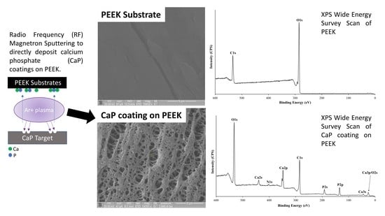
2.2. RF Magnetron Sputter Deposition

Sputtering targets were manufactured by dry pressing the hydroxyapatite (HA-(Plasma Biotal Captal-R), Tideswell, Buxton, UK) powder into low oxygen copper troughs (76 mm diameter and 5 mm thick) at a load of 40 kN for 10 min. RF Magnetron sputtering was undertaken using a designed Kurt J. Lesker Ltd, system (Hastings, UK), which was custom designed, operating with two Torus 3M sputtering sources operating at 13.56 MHz. The break-in prior to deposition from the HA target was conducted at a ramp rate of 5 watts (W) per minute up to the operating power of 150 W, whereby the source shutters were kept closed. The base pressure was below 5 × 10⁻⁶ Pa, with an argon gas flow rate (BOC, 99.995%) of between 15 and 20 Sccm, and a throw distance of 100 mm. During sputter deposition, the chamber pressure was maintained at 2 Pa. Table 1 outlines the sample nomenclature and key deposition parameters during the sputtering runs, with the deposition time being the main operating parameter varied during the experiments. The power density for these HA targets was approximately 3.3 W·cm−2 during each deposition.

2.3. X-ray Photoelectron Spectroscopy

X-ray Photoelectron Spectroscopy (XPS) of the samples was undertaken out using a Kratos Axis Ultra DLD spectrometer (Manchester, UK). Spectra were recorded by employing monochromated Al Kα X-rays (hν = 1486.6 electron volts (eV)) operating at 15 kV and 10 mA (150 W). Wide energy survey scans (WESS) were obtained at a pass energy of 160 eV. High resolution spectra were recorded for O 1s, Ca 2p, P 2p, and C 1s at a pass energy of 20 eV. The Kratos charge neutraliser system was used on all samples with a filament current of 2.05 A and a charge balance of 3.8 V. Sample charging effects on the measured binding energy (BE) positions were corrected by setting the lowest BE component of the C 1s spectral envelope to 285.0 eV, [20,21,22]. Photoelectron spectra were further processed by subtracting a linear background and using the peak area for the most intense spectral line of each of the detected elemental species to determine the % atomic concentration. In total, 3 areas were analysed from each sample. Peak fitting was carried out using a mixed Gaussian–Lorentzian (GL (30)) synthetic peak function using the Kratos Vision software (version 2.3.0).

2.4. Time of Flight Secondary Ion Mass Spectrometry (ToFSIMS)

ToFSIMS data was obtained using a ToFSIMS IV instrument(ION-TOF GmbH, Münster, Germany) equipped with a 25 keV Bismuth (Bi) liquid metal ion gun (primary ion source) with a pulsed target current of 0.3 pico Amps (pA) and a post accelerator voltage of 10 kV, both with an incident angle of 45° to the sample surface normal. A base pressure of 6.66 × 10⁻⁶ Pa was maintained in the UHV analyser chamber during the analyses by the ToF method. The negative and positive secondary ion spectra were recorded with a Primary Ion Dose Density of 1 × 10¹³ ions/cm−2. Charge compensation on the polymer surface was achieved using a low energy (21 eV) electron flood gun source, with the data acquired over a m/z range 0–200 for both positive and negative secondary ions. Data was presented by plotting m/z against intensity (counts/second). Ion images containing 256 × 256 pixels with 15 shots/pixel were acquired randomly, using Bi3+ primary ions in the high current bunched mode (HC-BU) over a 500 μm diameter area on the sample surface. Data acquisition and data processing and analysis were performed using SurfaceLab 6 (ION-TOF). The ToFSIMS IV instrument (ION-TOF GmbH, Münster, Germany) was also used to acquire depth profiles from the CaP modified PEEK samples, the instrument was equipped with a 20 keV Argon (Ar1900+) gas cluster ion gun which was rastered over the sample, with a crater size of 400 μm diameter, for 1000 secs. Analysis was completed using a Bi3+ liquid metal ion gun (primary ion beam) with an energy of 25 keV in a field of view (FOV) of 150 μm2 and a raster size of 128 × 128 pixels (random mode). Due to the insulating nature of the samples, a low energy (21 eV) electron flood gun source was applied for the purposes of charge compensation with a filament current of 2.5 A. In total, 3 areas were analysed from each sample.

2.5. Optical Profilometry

A Zeta-20 Optical Profilometer (KLA Instruments, Milpitas, CA, USA) was used to undertake analysis of the craters that were produced as a result of sputtering during the ToFSIMS depth profiling experiments. The profile of each crater was measured using a 20× lens with a z range of 44 µm, 400 steps with a step size of 0.111 µm across 10-line profiles at a working distance of 3.1 mm. The FOV with the high resolution 0.35× coupler 2/3” camera was 1169 × 876 µm2.

2.6. Scanning Electron Microscopy Experimental Parameters

SEM analysis of the samples was carried out using a Dual Beam Quanta 200 3D (FEI, Hillsboro, UK). Prior to imaging the surface, it was coated (~12–17 nm) in gold-palladium to reduce surface charge effects. The sample surface was sputter coated with gold-palladium using an Emitech K500X SEM preparation sputter system. The images contained in this work were collected at an accelerating voltage of 10 kV and a working distance of 8–15 mm. The average pore area, number of pores, and Feret’s diameter of the pores in each sputter deposited thin film were calculated using ImageJ software (Version 1.8.0) (National Institute of Health, Bethesda, MD, USA). In total, 3 areas were analysed from each sample.

2.7. Statistical Analysis

XPS, SEM, and ToFSIMS data in this study are reported as the mean ± standard deviation value (where N = 3). For the SEM analysis of the surfaces produced, a one-way analysis of variance (ANOVA) was applied to test for statistically significant differences between the sample types with a value of P < 0.05 considered to be statistically significant. The Bonferroni multiple comparison test was applied to compare values between successive pairs of sample types with the relevant outputs reported. All statistical analysis was performed using GraphPad Prism Version 3.0 software.

3. Results

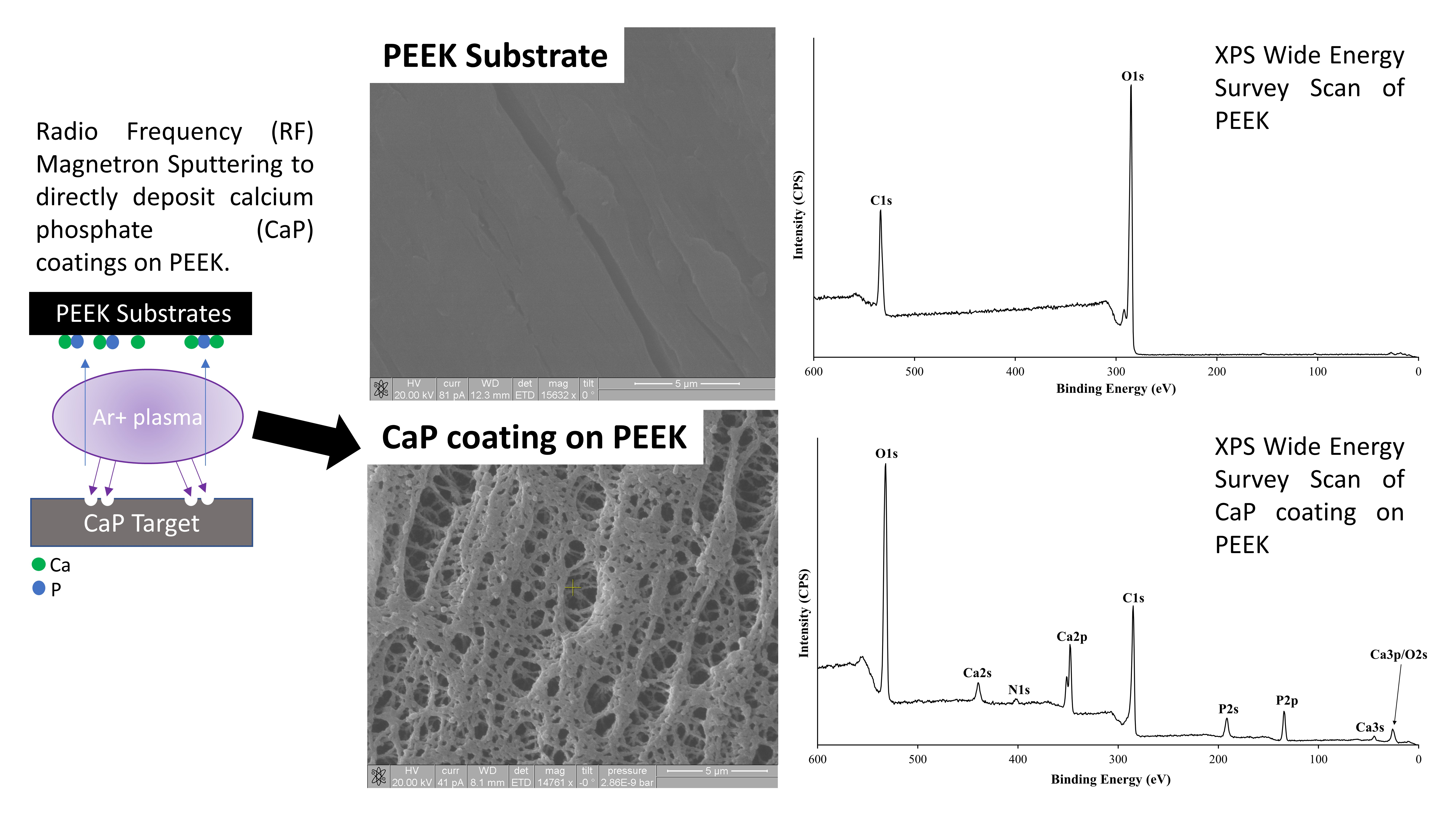
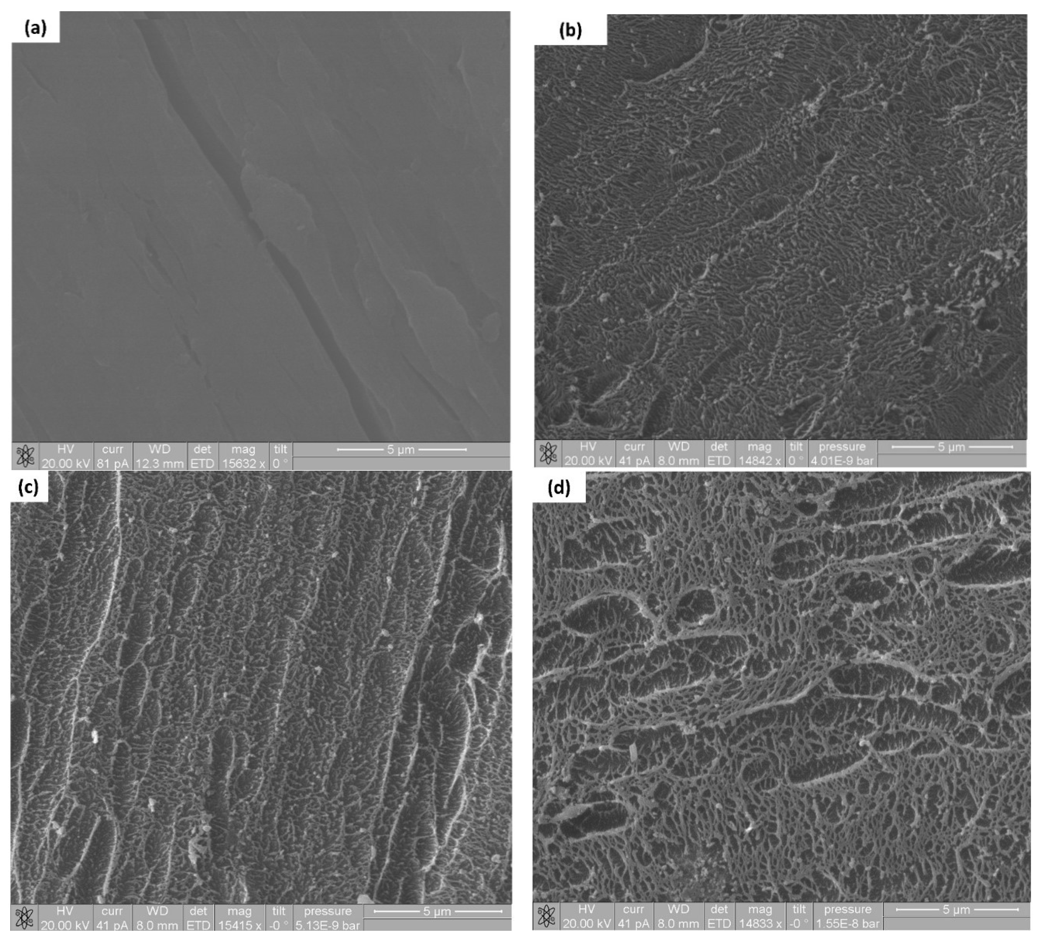
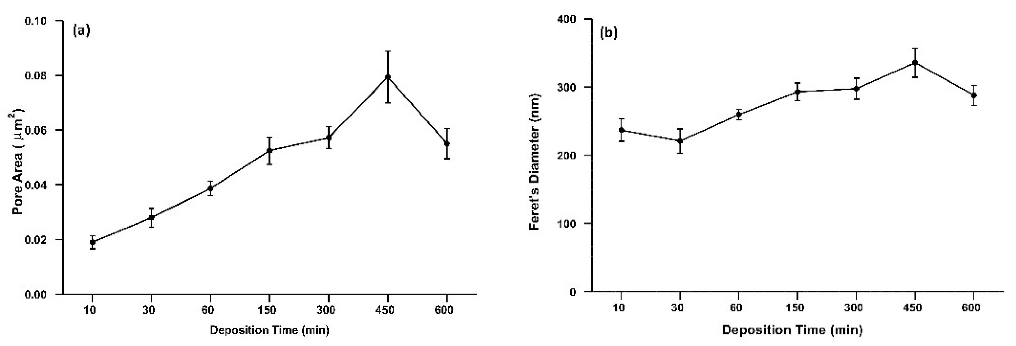
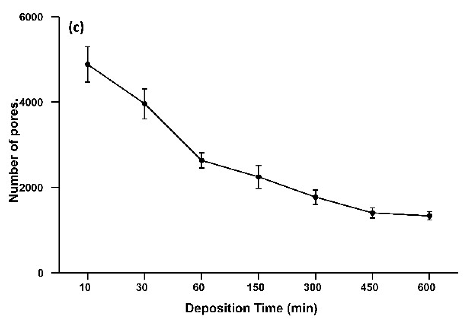
3.1. SEM Analysis of Time Deposition Study
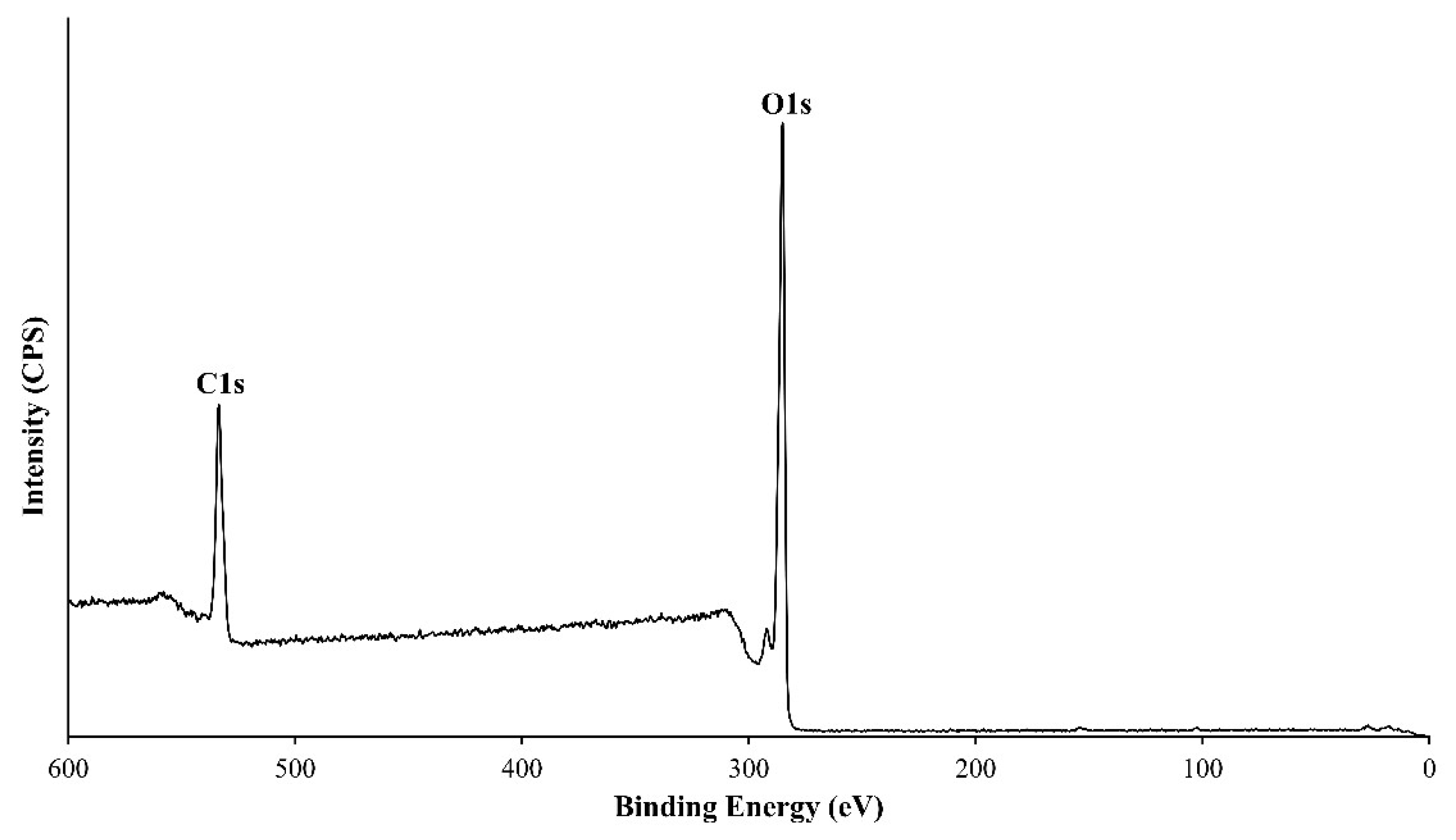
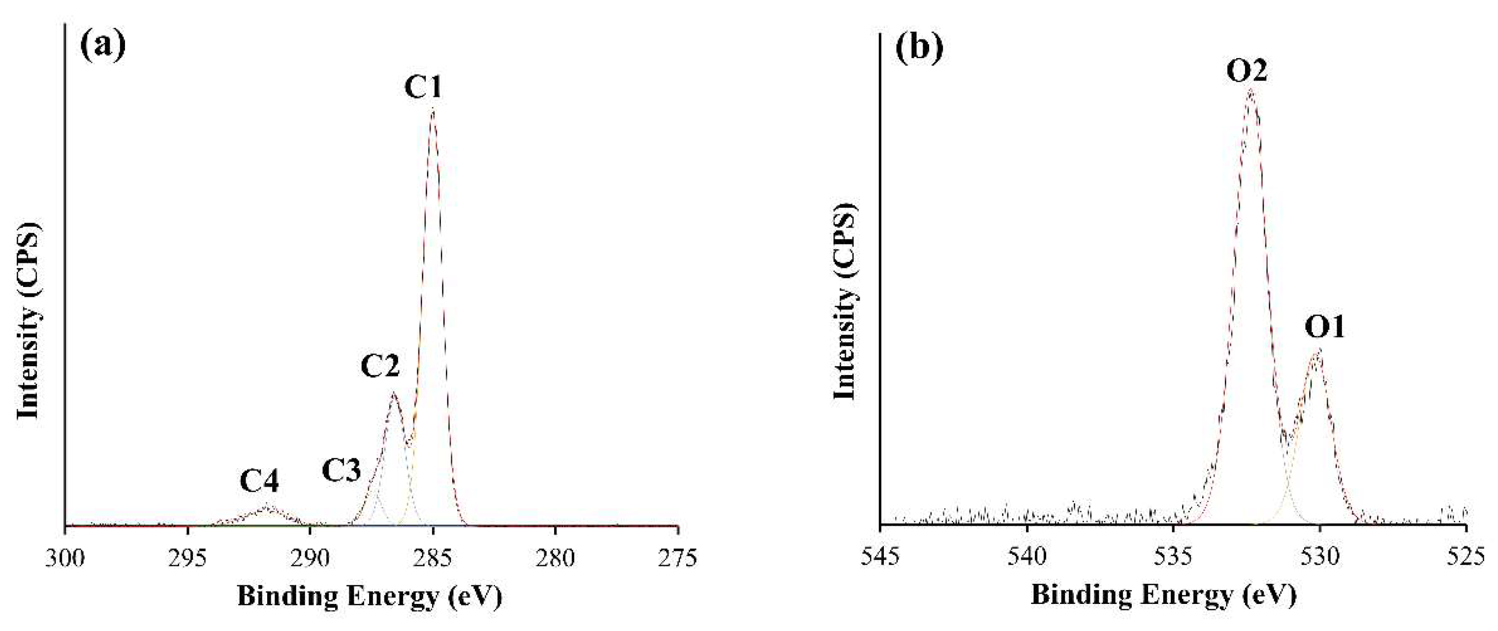
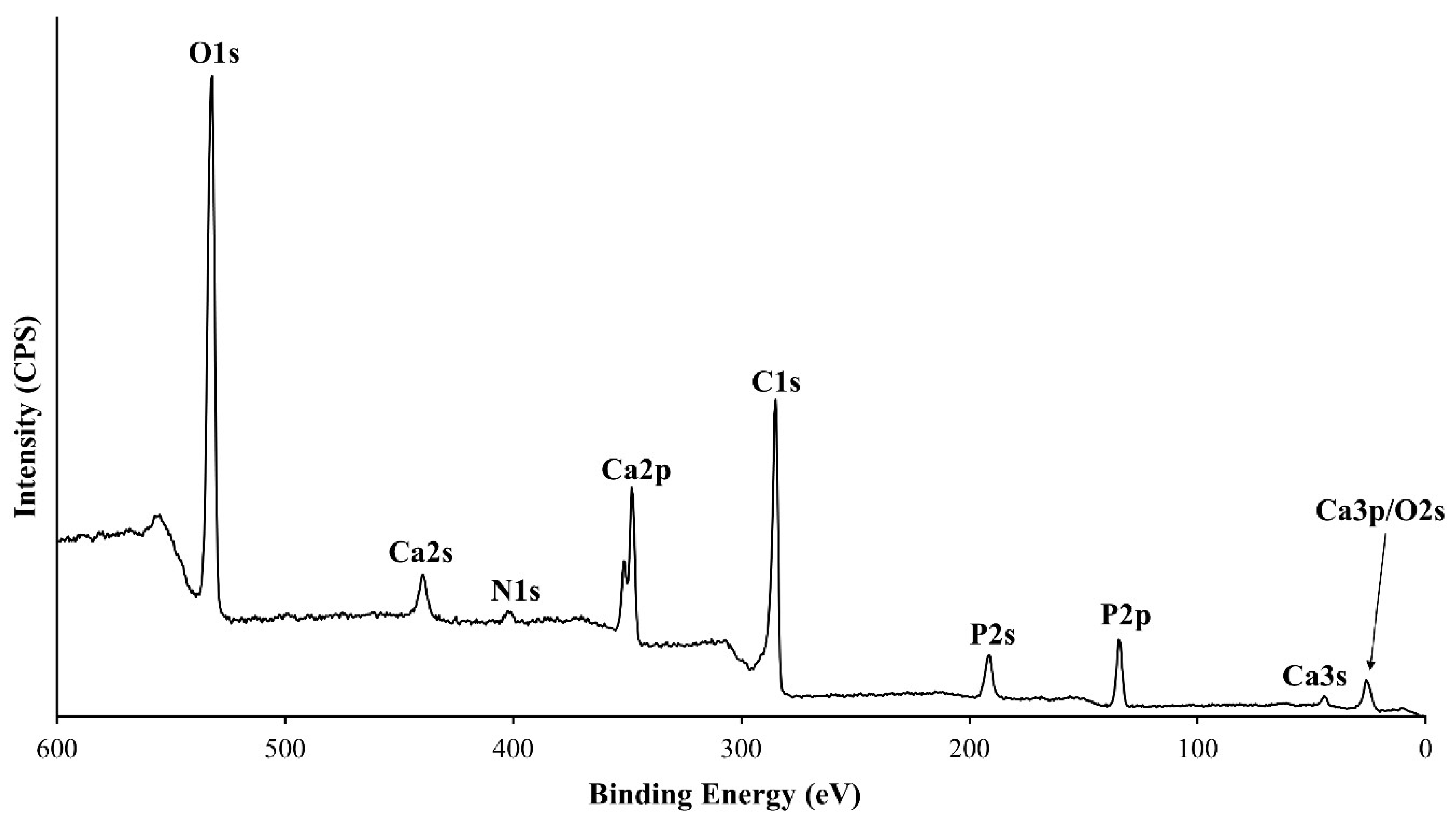
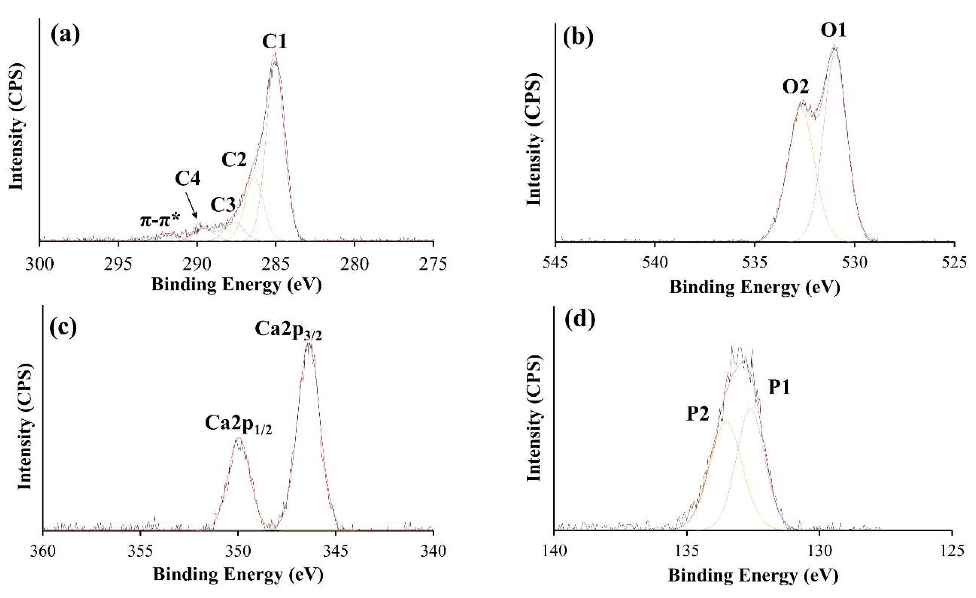
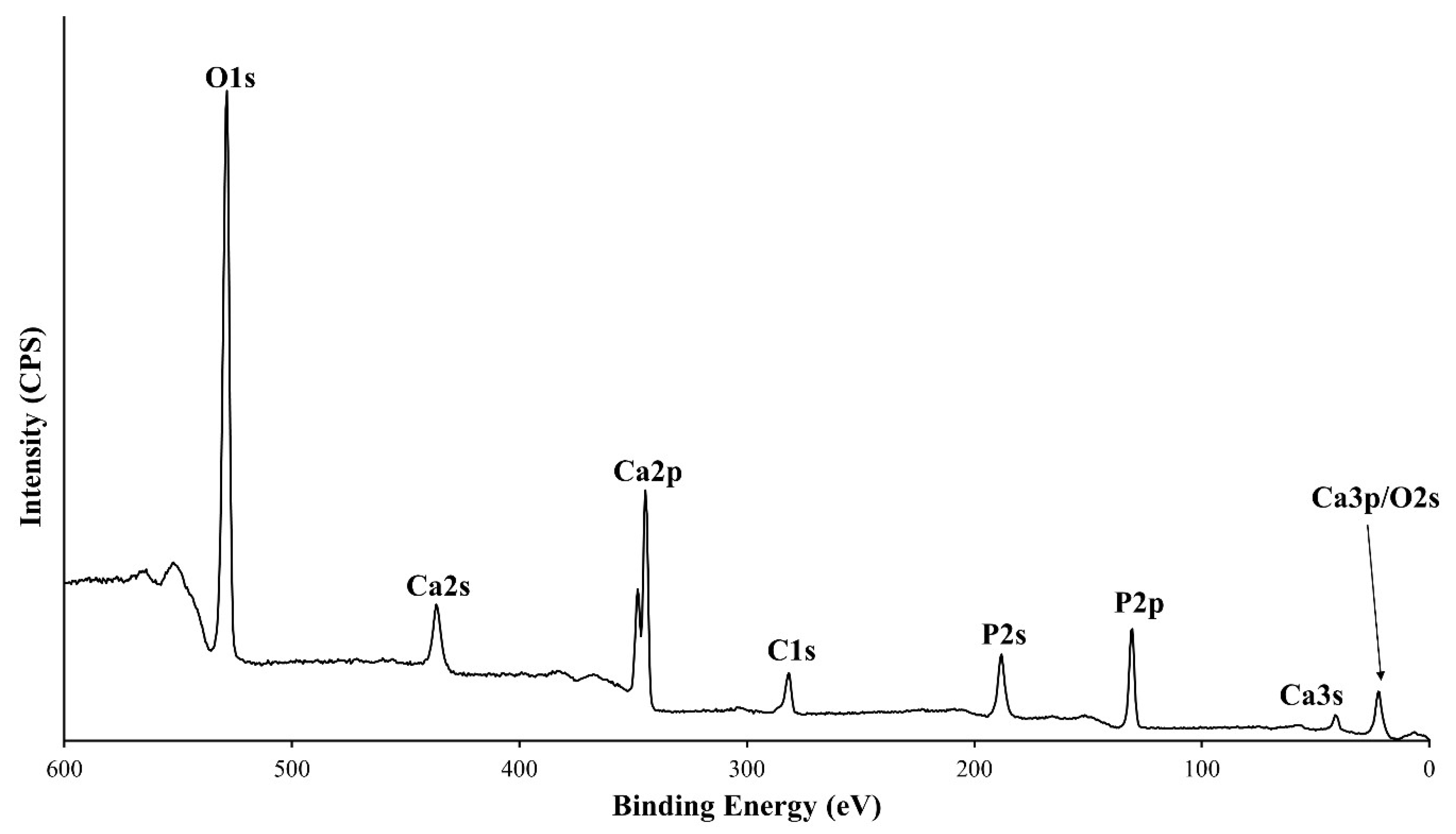
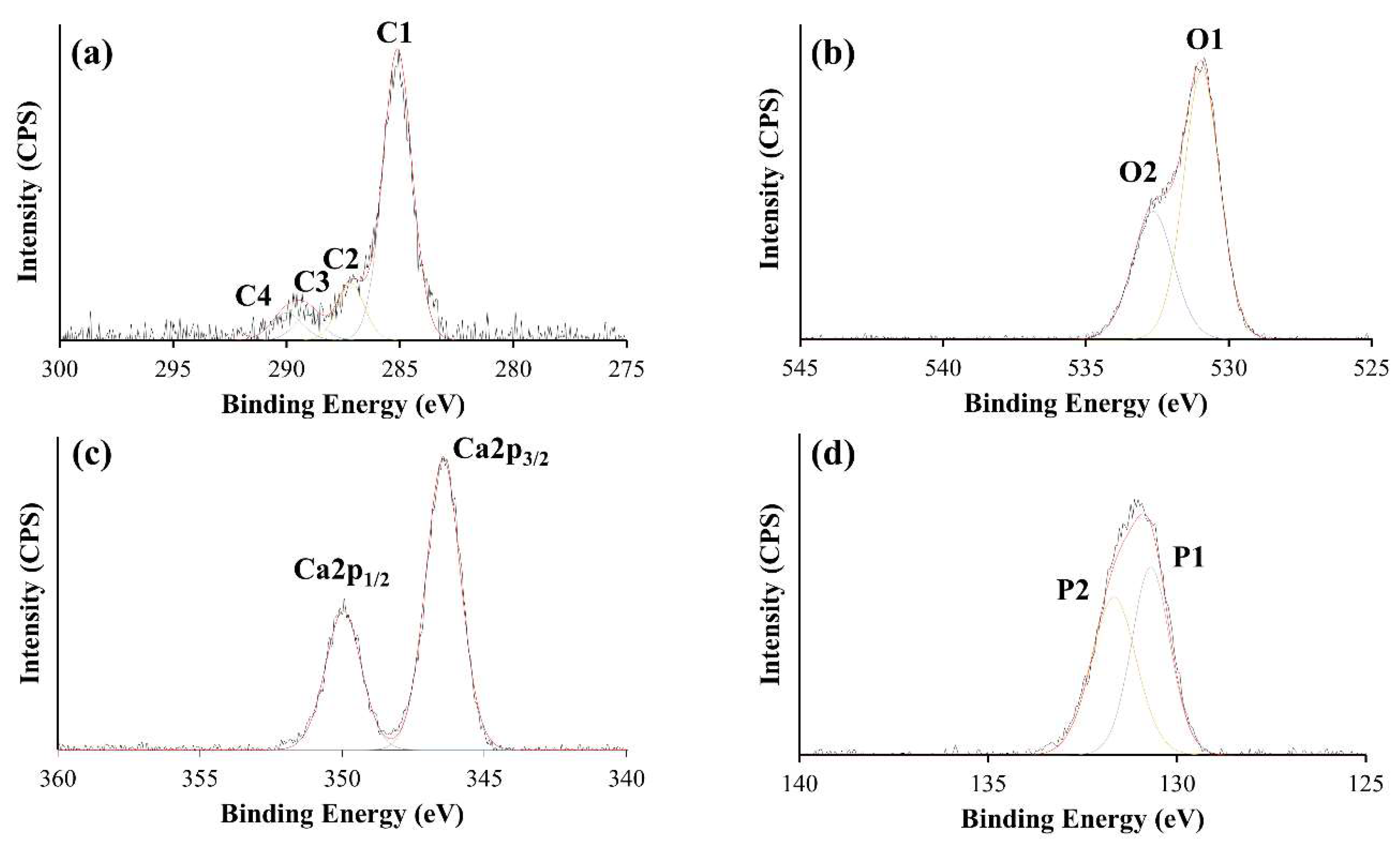
SEM analysis, as highlighted in Figure 1, was undertaken to examine the topographical nature of the pure PEEK substrates and the CaP thin film when the deposition time was varied. The SEM image for the pure PEEK substrate, highlighted in Figure 1a, illustrated a fairly flat surface with some scratches visible due to the abrasion of the surfaces. In comparison, the SEM images of HA modified PEEK (Figure 1b–h) indicated that there were marked differences between the topographies of each sample set (time deposition time points, 10–600 min, respectively). It is clear there were no voids in any of the thin films, and there was no evidence of cracking, delamination, and that the features shown below appear to be uniform. The initial interaction, as shown in Figure 1b (10 min deposition) and Figure 1c (30 min deposition), of the sputter deposited thin films and the PEEK material indicated that a physical change occurred on the surface of the PEEK material in the manner of ‘pitting’. As the deposition time continued the SEM analysis indicated the development of a ‘lattice-like’ microstructure (Figure 1d–h). The average pore area (Figure 2a) and Feret’s diameter (Figure 2b) for the pores was seen to generally increase with deposition time, until 450 min when they decreased. This was further corroborated with a calculation of the average number of pores per FOV as shown in Figure 2c. The number of pores declined with the increase in deposition time, which indicated that, with this coating process, there were fewer overall pores and that the pore area and diameter decreased, which indicated in-filling of the porous “lattice-like structure” as deposition time increased. The statistical comparison of the Feret’s diameter, average pore area and number of pores is presented in Table 2, Table 3, and Table 4, respectively.

3.2. XPS Analysis

The surface chemistry of the PEEK substrate, and CaP modified PEEK (HA10, HA60, HA300, and HA600) were all examined by XPS. The XPS analysis of the PEEK substrate, as shown in Figure 3 and Figure 4 (the wide Energy Survey Scan (WESS) and high resolution scans of the C1s and O1s regions, respectively) reveals that the uppermost surface (<10 nm) consisted of C and O only. Table 5 shows the C and O concentrations (Atomic Concentration %) measured at 88.02 ± 0.37 and 11.98 ± 0.37 respectively, and an O/C ratio of 0.14 for the PEEK substrate. This compares favourably with an O/C ratio of 0.16/1 for PEEK as highlighted in the literature [2,23,24,25].
Peak fitted high-resolution C 1s and O 1s spectra of PEEK are illustrated in Figure 4. The O 1s envelope (Figure 4a) revealed two peaks, the most intense peak attributable to the ether, O–C group, at 533.2 eV (O2) (73%) whilst the peak located at 531.1 eV (O1) was found to be indicative of the carbonyl group, C=O, (27%) [25,26]. The C 1s core level spectrum, as shown in Figure 4b has been peak fitted using four peaks, of which the highest intensity peak has been noted at 285.0 eV (C1), C–H and C–C bonds [27,28,29]. A further peak was noted at 286.6 eV (C2) which is known to correspond to the binding of C and O atoms, C–O ether bonding. A shoulder at the higher B.E of 287.5 eV (C3) is indicative of aromatic C bound to O, O=C carbonyl bonds [24,25]. The theoretical composition of the different C bonding peaks were found in literature to be approximately 68.5% (C1), ××.7% (C2) and 5.8% (C3) [24,25,28], with the relative proportion of the three types of C bonding found within study to be very similar at 67% (C1), 21% (C2) and 6% (C3), as shown in Table 5. A low intensity peak at a 291.8 eV, 5% (C4), has been attributed to a shakeup satellite, occurring due to the presence of π–π* transitions [24,25,28]. No peaks representative of HA were observed on the PEEK substrate. Wide Energy Survey Scans and high-resolution XPS spectra of CaP as-deposited thin films onto PEEK, for (HA10) and (HA600) are presented in Figure 5, Figure 6, Figure 7 and Figure 8.
Table 5 highlights the quantified result for the constituent elements of each of the high resolution O 1s, C 1s, Ca 2p, P 2p peaks including the Ca/P, and O/C ratios for each as-deposited surface. The C 1s envelope of the as-received PEEK HA10 thin film as shown in Figure 6a was observed as having three main peaks, representative of C–C/C–H, C–O, aromatic C=O, and CO32− species at 285.0 (C1), 286.5 (C2), 287.8 (C3), and 289.5 eV (C4), respectively, with the sample having exhibited a peak at the higher B.E of 291.7 eV indicating the presence of a π–π* shakeup. It is worth noting that 300 (HA300) and 600-min (HA600) samples did not contain the π–π* shakeup peak. This can be observed in Figure 8a for the HA600 sample. The O 1s peak for the HA10 sample, illustrated in Figure 6b, exhibits two separate constituents, with the most intense observed at 531.0 eV (O1). This peak has been known to indicate O–P/O=P bonding and the less intense peak, at 532.7 eV (O2) has been attributed to OH species/O–C bonding. The high-resolution spectrum for a HA10 deposited thin film has revealed a Ca 2p envelope comprised of a well-resolved doublet with a B.E position for Ca 2p3/2 being observed at 346.5 and Ca 2p1/2 at 350.0 eV, as highlighted in Figure 6c. The fitted P 2p spectral envelope, as illustrated in Figure 6d, displayed B.E positions of 132.6 and 133.5 eV, which represents P–O (P1) and P–OH (P2) bonds, respectively.
The peak positions for the HA60, HA300, and HA600 samples were very similar to those of the HA10 thin film onto PEEK. As the deposition time increased, so too did the % AC of O 1s, Ca 2p and P 2p, while the concentration of each of the fine components of C 1s decreased, as can be seen in Table 5. The Ca/P ratio for each of the as deposited thin films were very similar being 0.83 ± 0.04, 0.84 ± 0.03, 0.85 ± 0.03, and 0.86 ± 0.04 for the 10, 60, 300, and 600 min surfaces, respectively. The O/C ratios for each of the as deposited thin films were 0.69 ± 0.02, 1.23 ± 0.05, 2.06 ± 0.08, and 4.00 ± 0.08 for each of the 10, 60, 300, and 600 min surfaces, respectively.

3.3. ToFSIMS Study

In order to determine the presence or otherwise of particular chemical species, ToFSIMS was employed to provide information about the chemical nature of the outermost molecular layer (1–10 Å) of the PEEK and CaP modified PEEK (HA10, HA300 and HA600) samples via a mass survey. Given the high mass resolution of SIMS it was particularly well suited to polymer surface analysis; however, the analyses of PEEK via ToFSIMS has been scarcely described within the literature [27,28]. The positive and negative ion spectra for the PEEK polymer have been acquired in the relevant m/z ranges of 0–200. For the purposes of highlighting key results, the positive and negative ion spectra have been shown here between m/z ranges of 25–110 and 20–100, respectively.

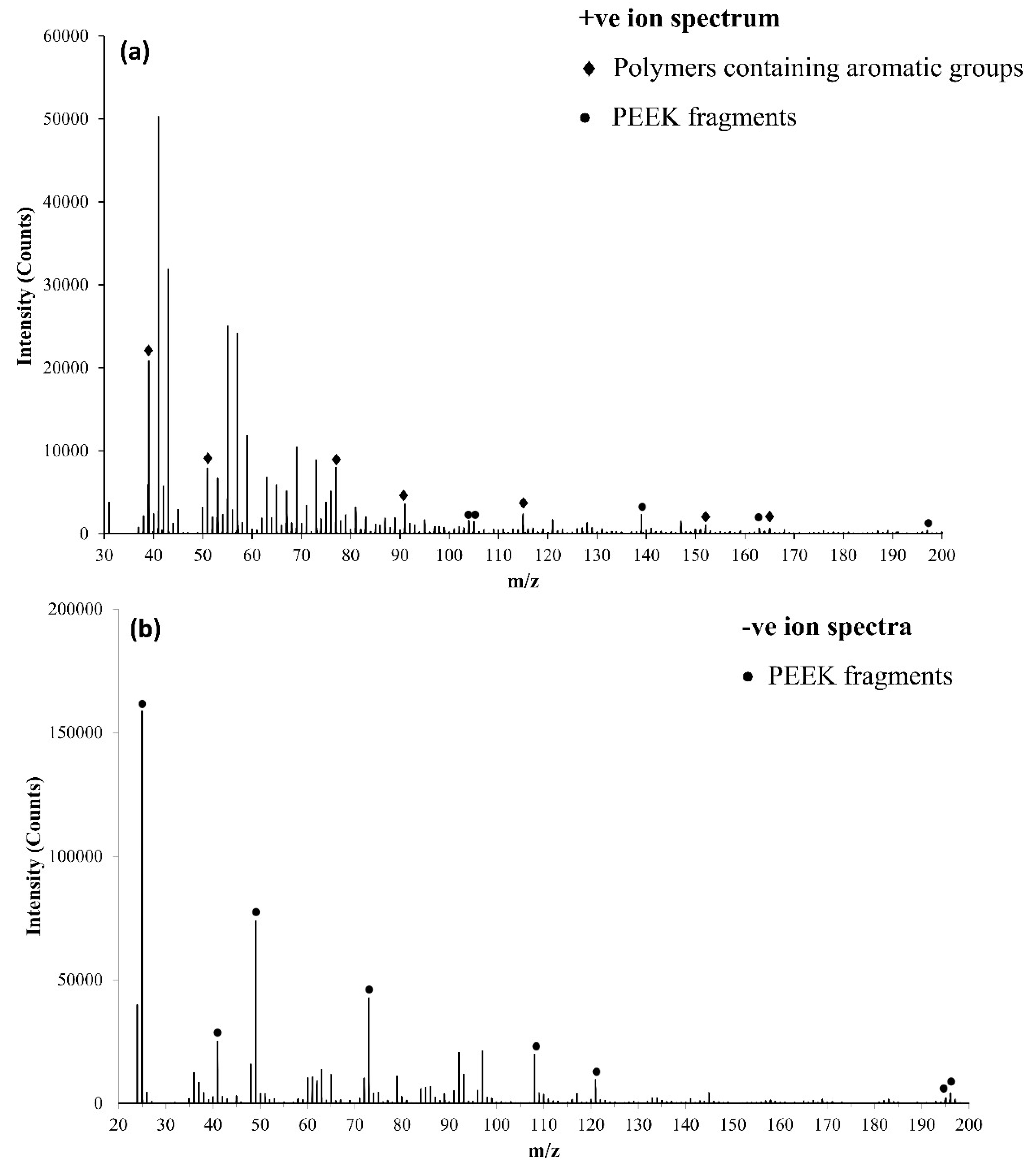
3.3.1. ToFSIMS Analysis of PEEK

From the positive survey for the PEEK substrate, as shown in Figure 9a, it can be noted that peaks above an m/z of 100 were very weakly detected. Specific peaks with a high intensity included m/z 39, 51, 77, 91, 104, 105, 115, 139, 152, 163, 165, and 195–197, these were all considered to be either indicative of aromaticity or ionically diagnostic of PEEK/PEEK fragments by Pawson et al. [28]. The peak at m/z 165 has been noted as useful in determining polymer structure as it contains no O [30]. In comparison, for the negative ion spectrum for the PEEK substrate (shown in Figure 9b), a range of peaks indicative of PEEK fragments were detected, including m/z 25, 41, 49, 73, 108, 121, and 196, which were recorded as corresponding to C2H, C2OH, C4H, C6H, C6H4O2, C7H5O2, and C13H8O2, respectively. The peak at the m/z ratio of 197 was assigned to the repeating structure of PEEK polymer.
Positive ion intensity surface maps for the PEEK substrate surfaces have been recorded in Figure 10a. The peaks at m/z 40 and 57 in Figure 10a (i) and (ii) have been known to represent Ca+ and CaOH+, respectively. Low levels of both ions and fragments, in comparison to a modified surface have been exhibited. The surface maps recorded for m/z 104, 139, and 163 (Figure 10a (iii)–(iv), respectively) are thought to be indicative and diagnostic of PEEK. Figure 10b has presented the negative ion intensity surface maps for the PEEK surfaces at the m/z detailed. The peaks at m/z 63 and 79 have been known to represent PO2 and PO3, (Figure 10b (i) and (ii)), respectively, low levels of both have been found to be present in comparison to a CaP modified surface. Due to handling and the nature of the sampling technique, some surface contamination was not unexpected. M/z 108, 121, and 196 peaks (Figure 10b (iii)–(iv)) have been assigned to the C6H4O2, C7H5O2, and C13H8O2 fragments, respectively; these were found to be present in a higher intensity in comparison to the modified surface. The images have indicated homogeneity of the selected ions (150 μm FOV) on the surface of the PEEK material. No unexpected species were detected; the samples were found to be relatively free from contamination.

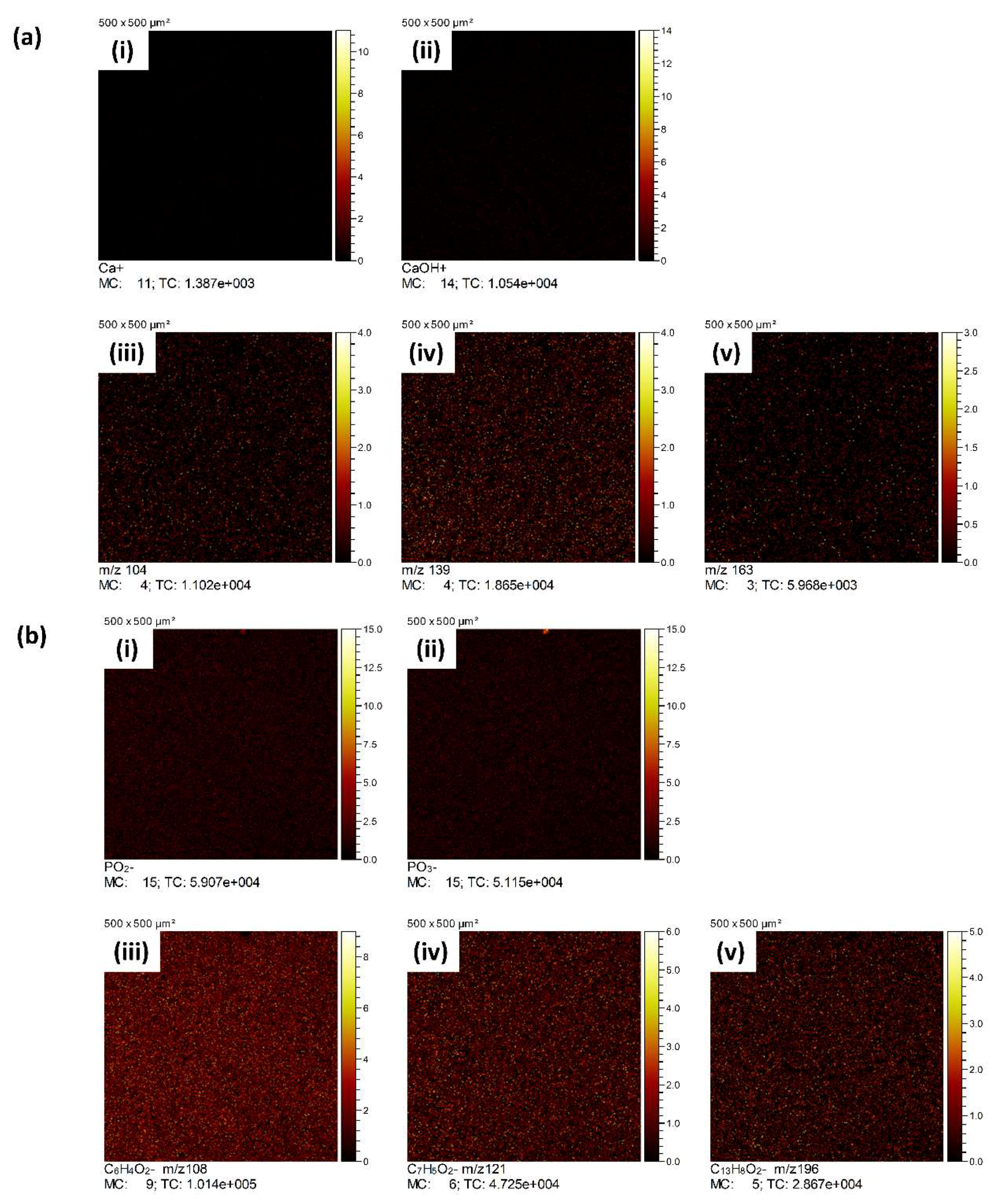
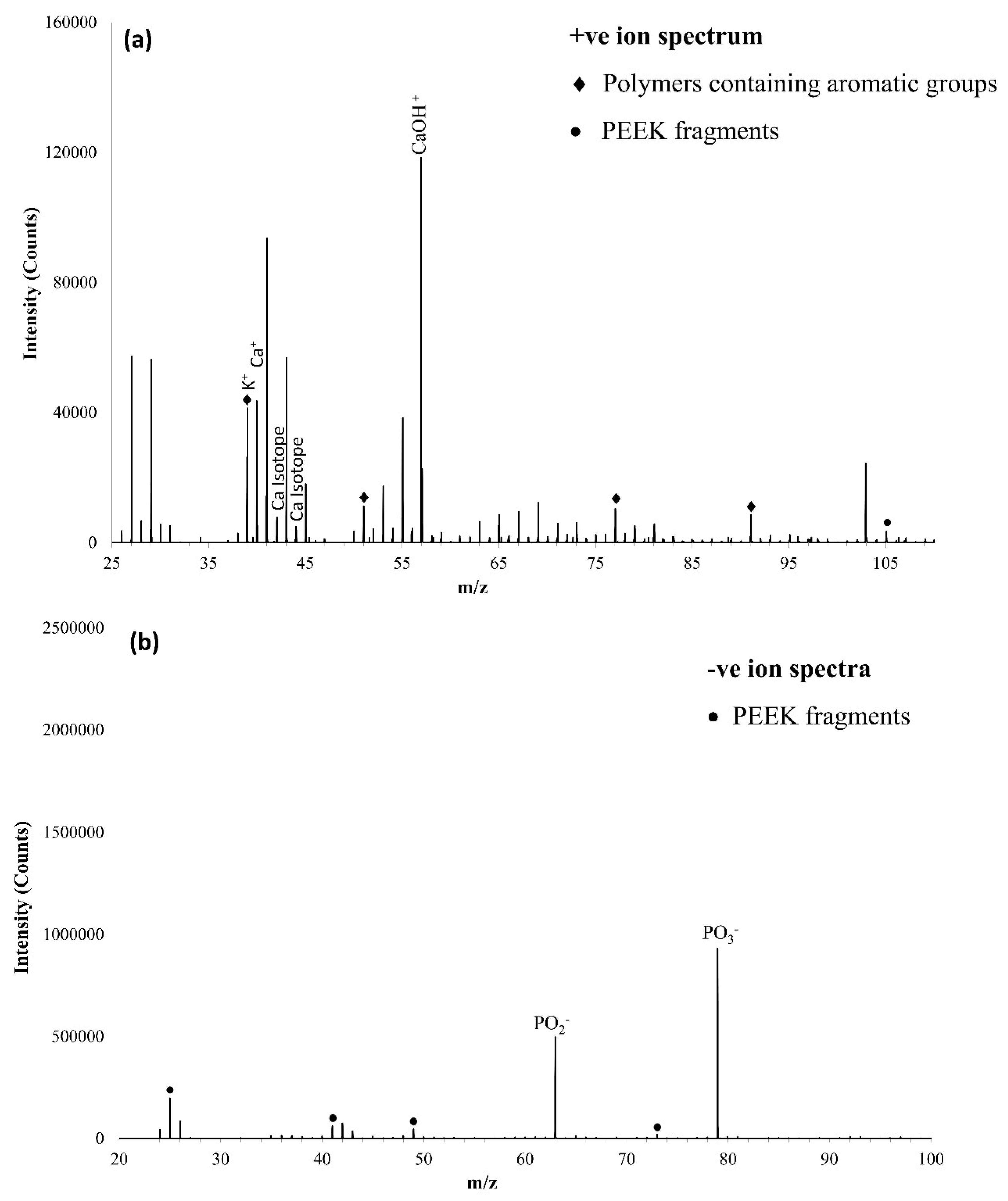
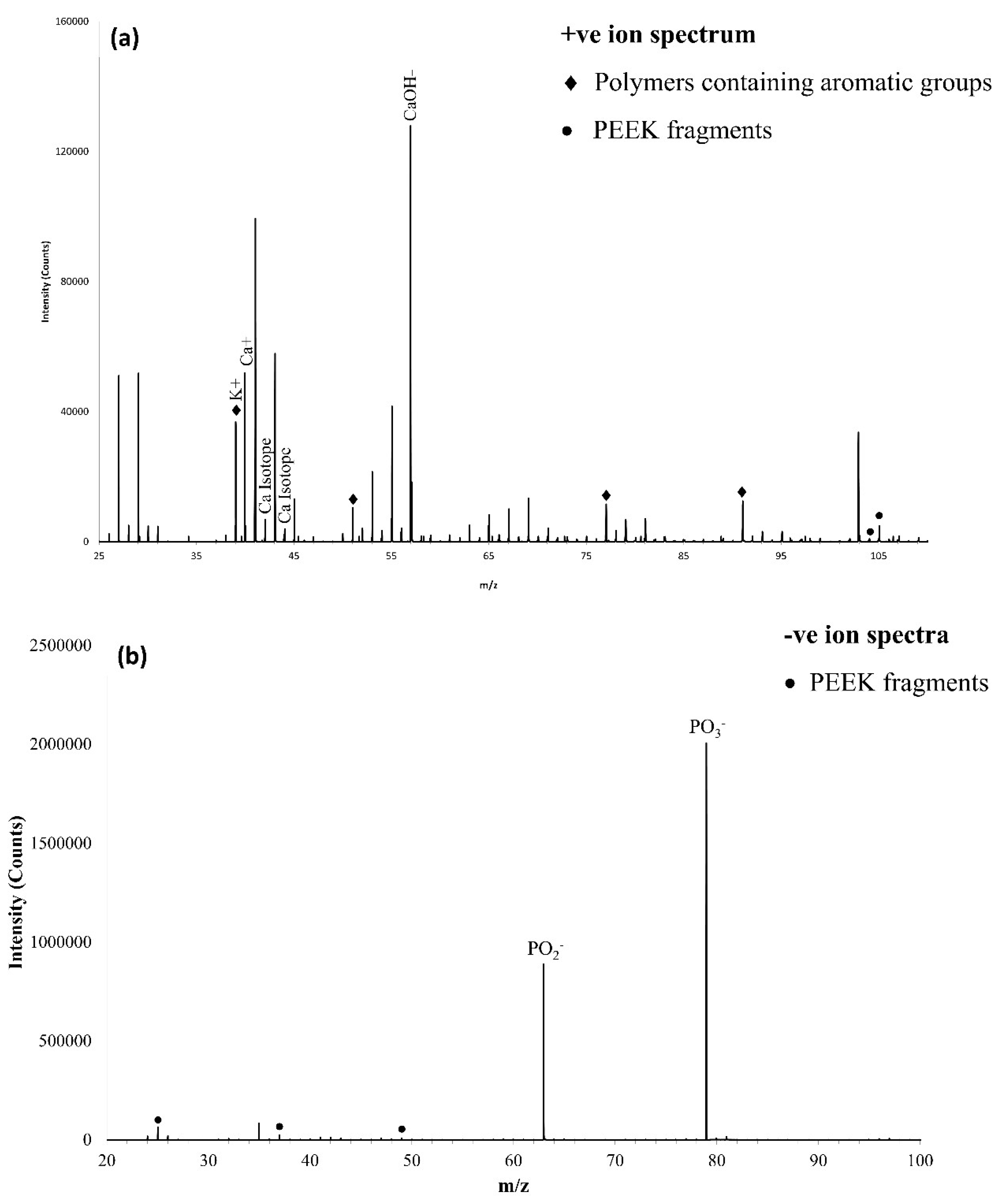
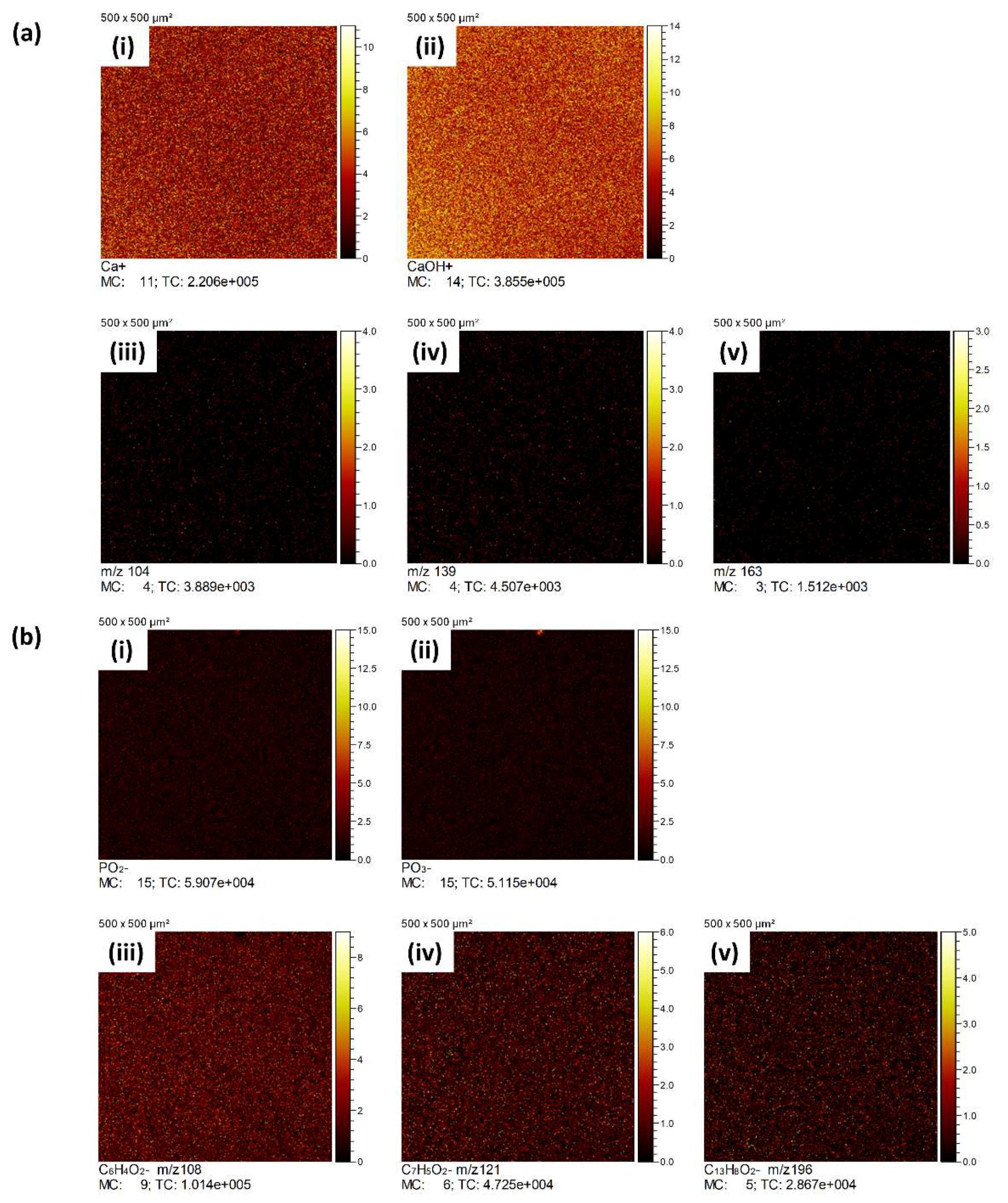
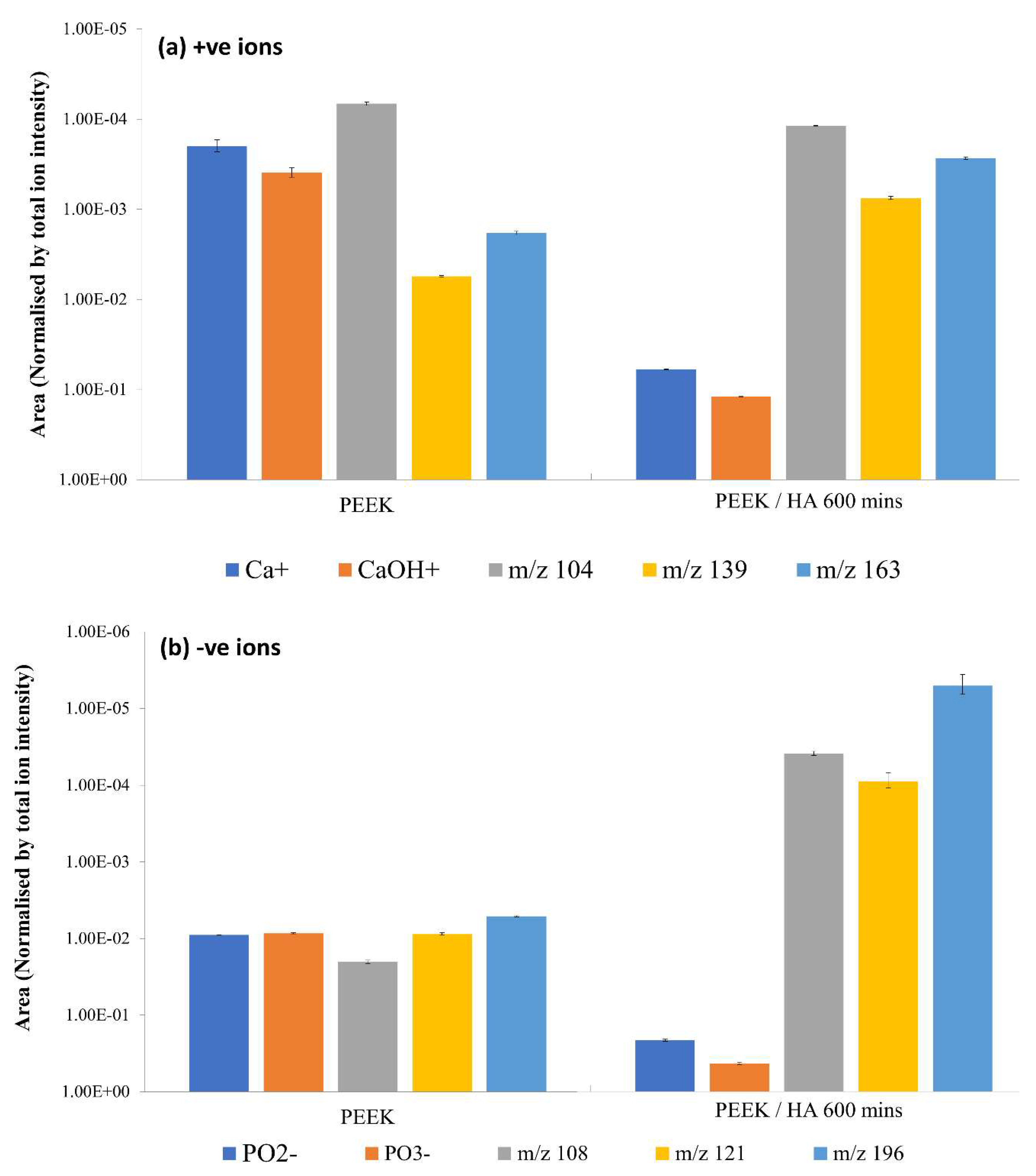
3.3.2. ToFSIMS Analysis of CaP Deposited onto PEEK over Time

The positive ion survey spectra of the CaP thin film sputter deposited onto the PEEK surface for up to 10 min (HA10), in the m/z 25–110 range is shown in Figure 11a, with characteristic peaks observed at an m/z ratio of 40 and 57 representative of Ca+ and CaOH+, respectively [9]. Isotopes of Ca+ were detected at m/z 42 and 44, and it was clear from looking at the survey spectra that the CaOH+ ion was dominant in comparison to the neat PEEK spectra. The presence of impurity ion K+ was noted at m/z 39. Peaks known to relate to polymers containing aromatic groups were found to be present at m/z 39, 51, 77, and 91. At m/z ratios above 100, there were two peaks, namely at 104 and 105, which were thought to be specific to PEEK [28] in this circumstance, and only the peak at 105 was considered to be significant (>0.4% of the largest peak) [9]. The negative ion survey of the CaP thin films sputter deposited onto the PEEK surface for up to 10 min in the m/z 20–100 range is shown in Figure 11b, with characteristic peaks within the spectra noted at an m/z 63 and 79 corresponding to PO2 and PO3. Peaks were also observed at 25, 41, 49, and 73, corresponding to the main negative fragments of PEEK, C2H, C2OH, C4H and C6H [27], these have been attributed to either PEEK or surface contamination due to their exposure to atmospheric conditions. Similar results were observed for figure the positive and negative ion spectra for the HA600 sample, as shown in Figure 12a,b, respectively. It is noted that the relative intensities of the PO2 and PO3 ions dominant the negative ion spectra for the HA600 surface, with the contribution from the PEEK significantly diminished. The ToFSIMS surface mapping positive and negative analysis for HA600 has been presented in Figure 13a,b, respectively, with similar results observed when compared to those of the HA10 samples in Figure 10. The positive and negative peak area (normalised by total ion count) bar charts for of the samples analysed here by ToFSIMS are shown in Figure 14a,b.

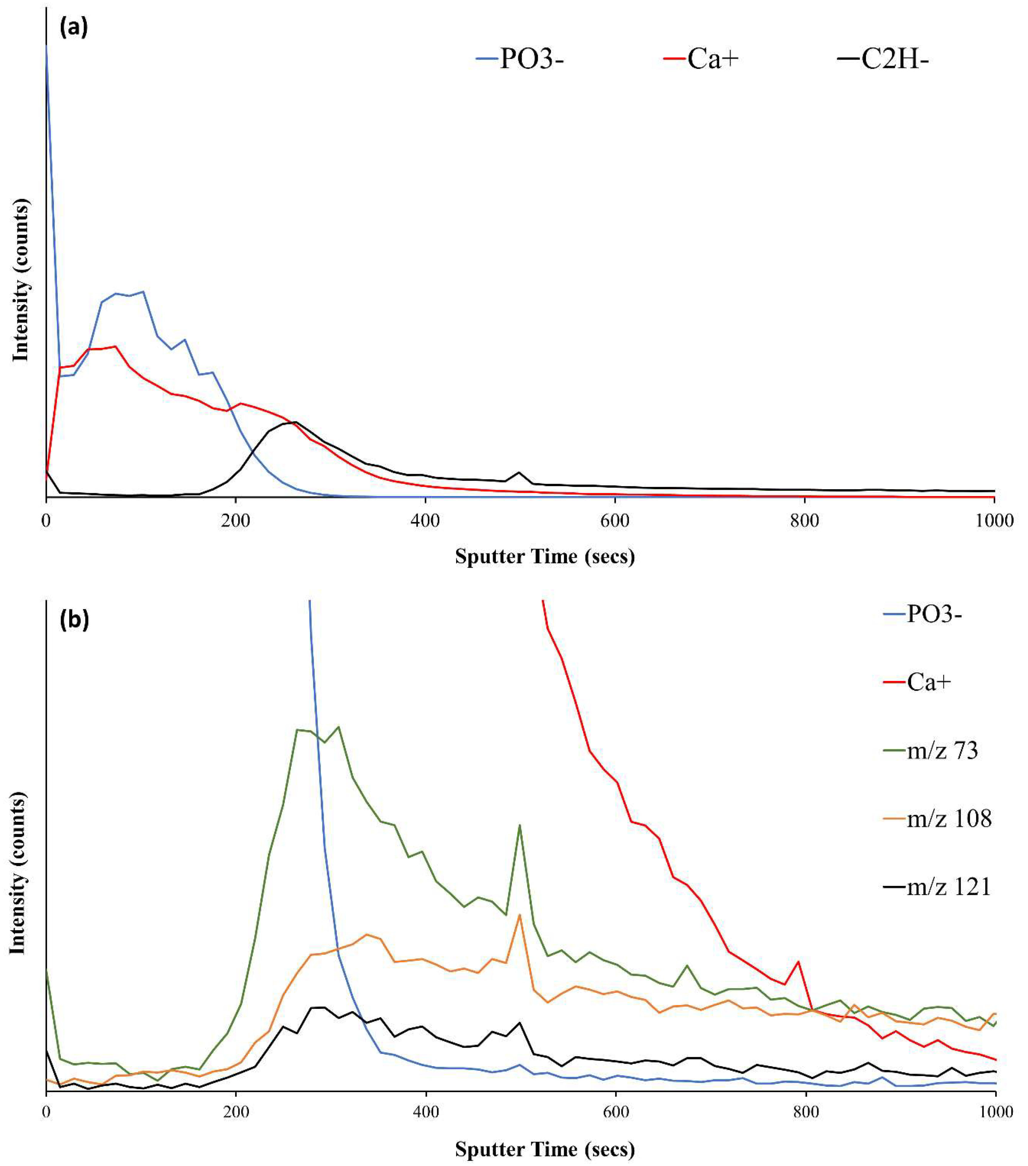
3.3.3. ToFSIMS Depth Profile of CaP Sputter Coated PEEK (HA600)

To further investigate the relationship between the sputtered surface and the PEEK substrate, ToFSIMS depth profiling was employed. The depth profile for HA600 modified PEEK in the positive and negative ion modes (1000 s rastering) is shown in Figure 15 (overlaid for both positive and negative ions). There was a decline in intensity of the P and Ca ions as they appeared to tail off in response to the Ar+ ion bombardment. There was a very slight, yet steady and continuous increase in the intensities correlating to the PEEK fragments, both negative and positive. These ions were expected to be in low intensity, whereas the hydrocarbon was expected to be much more intense. The ion intensity of the C2H hydrocarbon experienced an initial sharp decline at the very beginning of rastering; this was likely due to surface contamination, and was followed by an incline, followed by an exponential decrease to a less intense but steadier state. A further depth profile, taken using ToFSIMS, is shown in Figure 16a, probing only the PO3 and C4H ions (as shown in Figure 16b,c) representative of the CaP coating and PEEK substrate, respectively), highlights the fact that the there is significant intermixing of the coating and the PEEK substrate. The depth profilometry of the ToFSIMS sputter crater is illustrated in Figure 17 It was found that the sputter crater was, on average, 2.32 ± 0.19 µm.

4. Discussion

RFMS was successfully utilised to modify the surfaces of PEEK polymer at low temperatures with a CaP thin film. This was done with the objective of potentially enhancing the PEEK material’s surface bioactivity in preparation for exposure to physiological conditions. Through the manipulation of the sputtering parameters, namely deposition time, this work has shown that the desired CaP thin films can be achieved successfully, in a one step process, without the need for subsequent processing (e.g. thermal annealing), albeit at a CaP ratio below that expected for pure HA. To ascertain the potential of these surfaces, several different analytical techniques were used to characterise the resultant thin films chemically and physically, including ToFSIMS, XPS, and SEM. The XPS data obtained for PEEK was typical of this material. Each peak assignment for the curve fitted elements were as expected [24,25,26,28,29,31]. The O/C value obtained for PEEK, 14/1, was lower than that which was anticipated (16/1) [2,23,25], small deviations such as this have been attributed to the presence of hydrocarbon contamination on the PEEK surface [28]. With regard to the ToFSIMS analysis of PEEK, according to Pawson et al. [28] and Lub et al. [30], specific peaks, within the survey, at m/z of 39, 51, 77, 91, 115, 152, and 165 have been considered as representative of aromaticity, such as the structure of PEEK. The peak at m/z 165 was originally found in a polycarbonate, which is known as structurally very similar to that of PEEK, this particular peak has been recorded as being useful in determining the polymer structure as it contained no O, due to the polymer being analysed after rearrangement [30]. Peaks outlined by Pawson et al. [28] which were thought to be indicative of PEEK included m/z 104, 105, 139, 163, and 195–197. The peak at an m/z ratio of 39 has been treated with care as, according to literature, some of the intensity has been known to be attributed to potassium as a result of remnants left from the polymerisation process. It was not detected via XPS here. According to Pawson et al. [28], peaks below m/z 60 within the negative survey have not been found to be useful diagnostically and intensities are low, which, from looking at other literature, was expected. Work by Henneuse-Boxus et al. [27] has detailed a number of peaks for the m/z ratios of PEEK fragments which have been found within the negative survey presented here, these included 25, 41, 49, 73, 108, 121, and 196, which were recorded as corresponding to C2H, C2OH, C4H, C6H, C6H4O2, C7H5O2 and C13H8O2, respectively. The peak at the m/z ratio of 197 has been assigned to the PEEK monomer. Positive ion intensity surface maps for the PEEK surfaces have included peaks present at m/z 40 and 57, which represent Ca+ and CaOH+, respectively. Low levels of both ion fragments, in comparison to a modified surface, were noted as expected due to this surface being essentially pure PEEK (PEEK Optima LT1 grade). This intensity was likely contributed to by a fragment other than Ca+ or CaOH+. Fragments present at m/z 104, 139 and 163 are known to be indicative and diagnostic of PEEK, these were present in higher intensities than those of the CaP modified surface, this was expected. These ions have been commonly found in low intensities [28]. The ToFSIMS negative ion intensity surface maps for PEEK surfaces at the selected masses exhibited low levels of PO3 and PO2, in comparison to a CaP-modified surface, as expected due to the fact that this particular surface has had no exposure to any modification procedure. The surface maps for m/z 108, 121, and 196 have been associated with aromatic polymers or fragments of PEEK [27], it was expected that these would be present in a higher intensity than they were found, in comparison to a modified surface. CnHm clusters were observed in much higher intensities than the peaks chosen (m/z 108, 121, and 196) and are known as attributable to carbonaceous species, these have been thought of as generally indicative of a polymeric material; however, these were considered too generic to utilise on this occasion as, according to literature, they have not been considered diagnostic of PEEK [28]. SEM micrographs of PEEK modified with CaP via RFMS for various deposition times have been shown in Figure 1. The morphology of the surface of the polymer was characterised for time periods up to 600 min, during which time the polymer surface morphology developed, from the early time point of 10 min pitting of the surface could be clearly observed, whereas a more intricate lattice-like or network-type microstructure was exhibited at later time points. It was thought that this development was a consequence of the eventual coalescence of the pits to establish porosity via the nucleation and growth of the surface structures. The size of the pits, according to the area and Feret’s diameter calculations, has been shown to rise as time increased, until 450 min, when the dimensions started to decrease. This, along with the knowledge that the number of pores declined as time deposition increased, indicated that an infilling of the surface morphology has occurred after 450 min. The nature of the porous microstructure exhibited at latter deposition times was similar in nature to previous work [32,33,34,35] on polymers. As such, the surface of the PEEK substrates obviously undergo etching at the start of the sputtering process, with Ca and P species then becoming embedded into the PEEK and the resultant CaP coating nucleating from these embedded species, resulting in a hybrid intermixed zone between the coating and the substrate. Evidence for this hybrid intermixed CaP coating and PEEK substrate zone is shown by the cross-sectional depth profile illustrated in Figure 16, where there is clear overlap between the PO3 and C4H ions species (representative of the CaP coating and the PEEK substrate, respectively). It is suggested that, as the Ca and P species do not embed homogeneously over the entire surface during sputtering, this results in the formation of the lattice-like network as opposed to a normal dense, non-porous and continuous coating as normally observed with such coatings on metallic substrates [20].
In order to investigate the nature of the CaP thin films once they had been deposited onto the PEEK substrate, for depositions times 10, 60, 300, and 600 min, ToFSIMS was employed including the survey, surface mapping and depth profiling functionalities. XPS was used to investigate the chemistry at the time points (10, 60, 300, and 600 min). The positive ToFSIMS surveys were displayed in Figure 11a and Figure 12a for the samples HA10 and HA600, respectively. Each of the spectra displayed the characteristic peaks expected for a ToFSIMS analysis of a CaP modified surface [9,19,36]. In each spectrum, Ca+ species (m/z 40 and 57) as well as the isotopes (m/z 42 and 44) were present. Various peaks within the positive spectrum considered to be representative of polymers with aromatic groups were present (m/z 39, 51, 77, and 91) along with peaks thought indicative of PEEK (m/z 104 and 105). The negative ToFSIMS spectra for both the HA10 AND HA600 samples (Figure 11b and Figure 12b respectively), revealed the dominance of the key ion, P (m/z 63 and 79) for both time points. ToFSIMS results revealed that, as the length of time that the CaP material was sputter deposited onto the surface of the PEEK substrate increased, the relative intensity of the PEEK fragments diminished in both the positive and negative spectra, whilst the relative Ca and P intensities increased as shown in Figure 14. These results were consistent with the XPS results. The WESS and high-resolution spectra for XPS for the HA10 and HA600 samples (shown in Figure 5, Figure 6, Figure 7 and Figure 8) exhibited peaks which were characteristic of CaP materials and were as expected [9,12,37]. It was noted from these results that the Ca/P was very low for all the samples and well below the expected 1.67. Previous work by Surmenev et al, showed that the Ca/P ratio was much higher when HA was sputter deposited onto polymeric materials (PTFE), and that it was difficult to form CaP coatings on such substrates [38]. The results here are contradictory to those previous findings and are most likely due the build-up of negative charge on the surface of the insulating PEEK substrate. This prevents re-sputtering of P by negatively charged O, resulting in the low Ca/P observed here [39]. ToFSIMS surface mapping for both the PO2 and PO3 and Ca ions has shown a similar trend. Incidentally, it was also reported by various authors that both Ca and P travel from the target to the substrate as neutral species [38] depositing to form CaP thin films [40,41,42,43]. When analysing the ToFSIMS spectra, it was noted that PO2 and PO3 ions were dominant ions in the negative ToFSIMS survey, and with increasing deposition time their presence increased, correlating well with the increase in both O and P highlighted in the corresponding XPS. This information, along with the decrease in the C % AC, with time, caused the O/C ratio to increase. High levels of C present on the CaP–modified PEEK surfaces have been reported in literature [9]. It was considered that this level of C may have been due to ‘adventitious C contamination’ because of the adsorption of impurity hydrocarbons, which corroborated the ToFSIMS results. ToFSIMS analysis indicated that, in both the positive and negative surveys, the peaks thought to be representative of hydrocarbon clusters (CnHm) had high intensities, (m/z 29, 49, and 73); however, as deposition time increased, the intensity of these peaks depreciated. It was also considered that some of the intensity of the C 1s high resolution XPS scan may have been attributed to C–C/C–H bonds. It was postulated from analysing XPS and ToFSIMS data that the decrease in C intensity was attributable to the sputter deposited thin film growing with time and, therefore, fewer PEEK C–C/C–H bonds were being detected, as the detection depth limits of the XPS system was limited to ~5–10 nm. After 600 min of sputter deposition it was realised that a number of the peaks defined within literature as being specific and diagnostic of PEEK, m/z 104 and 105, were still being detected by ToFSIMS (detection limit of 1–2 nm); however, only the 105 peak was considered significant (>0.4% of largest peak) [9]. It was suggested that this peak may have been due to the presence of another organic species, as corroborated by XPS, and the porous nature of the surfaces produced; however, this does merit further investigation. The shakeup peak often affiliated with aromatic ring structures present in PEEK have been exhibited in the C1s high resolution survey scans for 10 and 60 min but have disappeared for the 300 and 600 min modifications. The XPS no longer detected the underlying polymer substrate from 300 min, which suggested that the thin film deposition had grown so that the polymer was out of the detection limits of the XPS instrument. ToFSIMS surface mapping showed a similar trend, whereby all six of the fragments for PEEK, in the positive and negative spectra, were reduced in comparison to the neat PEEK sample, while the Ca, PO2 and PO3 ions had increased intensities. The ratio of each bond within the C 1s scan to the total % AC of C was similar to that expected for PEEK for the 10 and 60 min deposition sample with the addition of the CO32− bonds having possibly stemmed from the modification of the substrate with amorphous HA as outlined by Surmenev et al. [44]. There was strong evidence that suggested that there was a formation of a hybrid interaction layer between the PEEK and CaP material. In order to investigate the chemical nature of the interaction, ToFSIMS depth analysis was carried out, revealing that the P-related ions are readily detected on the surface of the modified PEEK substrate to a depth of ~ 0.65 µm, whereas the Ca ion signal was detected for much longer and appeared to tail off. This data indicated that sputtered species were possibly embedded into the polymer material up to a depth of ~1.21 µm, as determined by Zeta analysis. It was suggested that, once the Ca embedded into the polymer, P proceeds to grow on this Ca rich layer, with all species known to be eligible for re-sputtering in the dynamic RFMS environment. Within the known literature [30,45] several potential hypotheses are provided as to the reason for intensity spikes of each ion of interest. It was thought that, in the case of this work, the most likely cause was matrix ionisation effects that have been associated with surface pollutants, such as an oxidation layer. The evidence to substantiate this event comes from the fact that oxidation was thought to coincide with the small spike in intensity for signals at the beginning of each depth profile [46]. Another potential hypothesis that has been recorded was that the full depth profile regime has been met after a few seconds of sputtering time. The interface between the CaP film and the PEEK substrate has been found to be denoted by a slow decay of both the Ca2+ and PO3 signals and the gradual appearance of the PEEK signals, which indicated the presence of a hybrid layer where the Ca ions were embedded into the PEEK material. The literature [47] has outlined the sequence of events leading to the formation of a CaP thin film via RFMS. At the initial stages of deposition an enrichment of Ca at the substrate surface is known to take place, thought to be due to the re-sputtering of P ions, leading to a Ca/P higher than stoichiometric HA. This work has not highlighted this trend as the surface at 10 min (the HA10 sample) has been shown by XPS analysis to have already become P rich. It was thought to be the case that the investigation would have needed to have been carried out much earlier to replicate the Ca enrichment trend, as within the work completed by López et al. [48]. Evidence to conclude that Ca was indeed embedded into the PEEK material intensified as it was realised that there was less % AC of Ca-related material on the polymer surface in comparison to the thin films sputtered onto Ti, under the same conditions in previous work by the authors [3,7,20]. It is suggested that this may have been due to the heavier nature of Ca, in comparison to the P ion during bombardment, or the softer nature of the polymer substrate. This would account for the P rich surface, the lower than expected Ca/P ratio, as well as the lower than expected Ca intensity in the ToFSIMS survey scans at all time points.
Ideally, here the aim was to produce CaP coatings onto PEEK to provide a means to enhance their bioactivity. Key to this was to produce coatings that have properties commensurate with those properties outlined in the ISO 13,779 2 (2018) and ASTM F1609 standards, ideally mimicking the properties of HA, with a Ca/P ratio of around 1.67. It is clear from the results produced here that this has not been achieved as the reported Ca/P ratios are well below 1.0. The next phase of any work here would be to optimise the sputtering process to achieve enhanced coating properties to align with the ISO and ASTM standards. Aspects of substrate biasing, the process gas pressure, and the process gas used would all be important in order to achieve this. It would also be important to undertake mechanical testing of the coatings, understanding the coating thickness better, and importantly understanding the dissolution behaviour of these surfaces before progressing to more involved in vitro testing of these surfaces. If the appropriate chemical, physical, mechanical, and in vitro properties were achieved, these coatings could provide a basis for enhancing the bioactivity of PEEK materials for use in orthopaedics in order to improve bone apposition, both in terms of how quickly this can be achieved and the enhancement of the bond with bone when compared to pure PEEK devices.

5. Conclusion

From the results obtained here, it is clear that the RF magnetron sputtering has the capability to be utilised to sputter deposit, in a one-step (direct) process, homogeneous, and amorphous CaP surfaces that consist of a porous micro-/nano-structured lattice network containing appreciable levels of both Ca and P at low deposition powers (150W). It was realised that the manipulation of the deposition time had a significant influence on the chemical and physical properties of the resultant thin films, particularly in relation to the surface topography, pore area, pore diameter, and number of pores. The Ca/P of the resultant modification was low; too low in fact to coincide with HA or other bioactive CaP phases at ~0.85. It was postulated that this was due to the bombardment of the sputtered species coming into the contact with the polymeric material, causing species to embed into the PEEK substrate, which created a matrix interlayer between the CaP material and the PEEK substrate. Further to this, the build-up of a negative charge on the insulation PEEK surface prevented re-sputtering of the P species on the surface of the surface, as would normally be observed. It was indicated that the initial 60 min of sputter deposition could be an erosion/deposition process with the capability of causing physical and chemical alterations to the surface of the underlying polymeric substrate. The next step in this work would be to investigate the mechanical properties and the dissolution behaviour of the surfaces in physiological conditions, and to determine their in vitro potential using osteoblasts.

Author Contributions

Conceptualization, A.R.B., B.J.M., and L.R.; methodology, A.R.B., J.G.A., S.H., and L.R.R.; software, L.R., S.H., J.G.A., and A.R.B.; validation, S.H., L.R., J.G.A., B.J.M., and A.R.B.; formal analysis, S.H., L.R., J.G.A., B.J.M., and A.R.B.; investigation, L.R., S.H., J.G.A., and A.R.B.; resources, A.R.B. and B.J.M.; data curation, L.R., S.H., J.G.A., and A.R.B.; writing—original draft preparation, L.R., S.H., and A.R.B.; writing—review and editing, S.H., L.R., J.G.A., B.J.M., and A.R.B.; visualization, L.R., S.H., J.G.A., and A.R.B.; supervision, A.R.B. and B.J.M.; project administration, A.R.B. and B.J.M.; funding acquisition, A.R.B. and B.J.M. All authors have read and agreed to the published version of the manuscript.

Funding

This research was funded by the Department for the Economy (Northern Ireland) and the Meehan Family Scholarship, which facilitated part of the ToF-SIMS experiments.

Acknowledgments

The authors would like to acknowledge the support of Invibio Ltd., (Thornton Cleveleys, UK), particularly Mark Brady, who kindly provided PEEK-OPTIMA™ LT1 samples for these experiments. The authors would also like to acknowledge David Scurr and Matthew Piggott at the Interface and Surface Analysis Centre, University of Nottingham for their assistance with the ToFSIMS experiments.

Conflicts of Interest

The authors declare no conflict of interest.

References

  1. Rabiei, A.; Sandukas, S. Processing and evaluation of bioactive coatings on polymeric implants. J. Biomed. Mater. Res. Part. A 2013, 101, 2621–2629. [Google Scholar] [CrossRef]
  2. Ha, S.W.; Kirch, M.; Birchler, F.; Eckert, K.L.; Mayer, J.; Wintermantel, E.; Sittig, C.; Pfund-Klingenfuss, I.; Textor, M.; Spencer, N.D.; et al. Surface activation of polyetheretherketone (PEEK) and formation of calcium phosphate coatings by precipitation. J. Mater. Sci. Mater. Med. 1997, 8, 683–690. [Google Scholar] [CrossRef] [PubMed]
  3. Boyd, A.R.; Rutledge, L.; Randolph, L.D.; Meenan, B.J. Strontium-substituted hydroxyapatite coatings deposited via a co-deposition sputter technique. Mater. Sci. Eng. C Mater. Biol. Appl. 2015, 46, 290–300. [Google Scholar] [CrossRef] [PubMed]
  4. Gloria, A.; Manto, L.; Santis, R.D.E.; Ambrosio, L. Biomechanical behavior of a novel composite intervertebral body fusion device. J. Appl. Biomater. Biomech. 2008, 6, 163–169. [Google Scholar] [PubMed]
  5. Gloria, A.; Russo, T.; D’Amora, U.; Santin, M.; Santis, R.; De Ambrosio, L. Customised multiphasic nucleus/annulus scaffold for intervertebral disc repair/regeneration. Connect. Tissue Res. 2019, 61, 152–162. [Google Scholar] [CrossRef] [PubMed]
  6. Duarte, R.M.; Correia-Pinto, J.L.; Reis, R.C.; Duarte, A.R.C. Advancing spinal fusion: Interbody stabilization by in situ foaming of a chemically modified polycaprolactone. J. Tissue Eng. Regen. Med. 2020, 14, 1465–1475. [Google Scholar] [CrossRef]
  7. O’Kane, C.; Duffy, H.; Meenan, B.J.; Boyd, A.R. The influence of target stoichiometry on the surface properties of sputter deposited calcium phosphate thin films. Surf. Coat. Technol. 2008, 203, 121–128. [Google Scholar] [CrossRef]
  8. Storrie, H.; Stupp, S.I. Cellular response to zinc-containing organoapatite: An in vitro study of proliferation, alkaline phosphatase activity and biomineralization. Biomaterials 2005, 26, 5492–5499. [Google Scholar] [CrossRef]
  9. Lu, H.B.; Campbell, C.T.; Graham, D.J.; Ratner, B.D. Surface characterization of hydroxyapatite and related calcium phosphates by XPS and TOF-SIMS. Anal. Chem. 2000, 72, 2886–2894. [Google Scholar] [CrossRef]
  10. Aina, V.; Bergandi, L.; Lusvardi, G.; Malavasi, G.; Imrie, F.E.; Gibson, I.R.; Cerrato, G.; Ghigo, D. Sr-containing hydroxyapatite: Morphologies of HA crystals and bioactivity on osteoblast cells. Mater. Sci. Eng. C Mater. Biol. Appl. 2013, 33, 1132–1142. [Google Scholar] [CrossRef]
  11. Wolke, J.G.C.; Van Der Waerden, J.P.C.M.; De Groot, K.; Jansen, J.A. Stability of radiofrequency magnetron sputtered calcium phosphate coatings under cyclically loaded conditions. Biomaterials 1997, 18, 483–488. [Google Scholar] [CrossRef] [Green Version]
  12. Long, J.D.; Xu, S.; Cai, J.W.; Jiang, N.; Lu, J.H.; Ostrikov, K.N.; Diong, C. Structure, bonding state and in-vitro study of Ca–P–Ti film deposited on Ti6Al4V by RF magnetron sputtering. Mater. Sci. Eng. C 2002, 20, 175–180. [Google Scholar] [CrossRef]
  13. Bolbasov, E.N.; Rybachuk, M.; Golovkin, A.S.; Antonova, L.V.; Shesterikov, E.V.; Malchikhina, A.I.; Novikov, V.; Anissimov, Y.; Tverdokhlebov, S. Surface modification of poly (l-lactide) and polycaprolactone bioresorbable polymers using RF plasma discharge with sputter deposition of a hydroxyapatite target. Mater. Lett. 2014, 132, 281–284. [Google Scholar] [CrossRef] [Green Version]
  14. Tverdokhlebov, S.I.; Bolbasov, E.N.; Shesterikov, E.V.; Antonova, L.V.; Golovkin, A.S.; Matveeva, V.G.; Petlin, D.; Anissimov, Y. Modification of polylactic acid surface using RF plasma discharge with sputter deposition of a hydroxyapatite target for increased biocompatibility. Appl. Surf. Sci. 2015, 329, 32–39. [Google Scholar] [CrossRef] [Green Version]
  15. Tverdokhlebova, S.I.; Bolbasova, E.N.; Shesterikova, E.V.; Malchikhinaa, A.L.; Novikovb, V.A.; Anissimovc, Y.G. Research of the surface properties of the thermoplastic copolymer of vinilidene fluoride and tetrafluoroethylene modified with radio-frequency magnetron sputtering for medical application. Appl. Surf. Sci. 2012, 263, 187–194. [Google Scholar] [CrossRef] [Green Version]
  16. Socol, G.; Macovei, A.M.; Miroiu, F.; Stefan, N.; Duta, L.; Dorcioman, G.; Mihailescu, I.; Petrescu, S.; Stan, G.; Marcov, D.; et al. Hydroxyapatite thin films synthesized by pulsed laser deposition and magnetron sputtering on PMMA substrates for medical applications. Mater. Sci. Eng. B Solid State Mater. Adv. Technol. 2010, 169, 159–168. [Google Scholar] [CrossRef]
  17. Ivanova, A.A.; Surmeneva, M.A.; Tyurin, A.I.; Pirozhkova, T.S.; Shuvarin, I.A.; Prymak, O.; Epple, M.; Chaikina, M.; Surmenev, R.A. Fabrication and physico-mechanical properties of thin magnetron sputter deposited silver-containing hydroxyapatite films. Appl. Surf. Sci. 2016, 360, 929–935. [Google Scholar] [CrossRef]
  18. Van Dijk, K.; Verhoeven, J.; Marée, C.H.M.; Habraken, F.H.P.M.; Jansen, J.A. Study of the influence of oxygen on the composition of thin films obtained by r.f. sputtering from a Ca5(PO4)3 OH target. Thin Solid Film. 1997, 304, 191–195. [Google Scholar] [CrossRef]
  19. Boyd, A.R.; Rutledge, L.; Randolph, L.D.; Mutreja, I.; Meenan, B.J. The deposition of strontium-substituted hydroxyapatite coatings. J. Mater. Sci. Mater. Med. 2015, 26, 65. [Google Scholar] [CrossRef]
  20. Boyd, A.R.; O’Kane, C.; Meenan, B.J. Control of calcium phosphate thin film stoichiometry using multi-target sputter deposition. Surf. Coat. Technol. 2013, 233, 131–139. [Google Scholar] [CrossRef]
  21. Thomas, S.; Durand, D.; Chassenieux, C.; Jyotishkumar, P. Handbook of Biopolymer-Based Materials: From Blends and Composites to Gels and Complex Networks; John Wiley & Sons: Hoboken, NJ, USA, 2013. [Google Scholar]
  22. ASTM International. Standard Guide to Charge Control and Charge Referencing Techniques in X-ray Photoelectron Spectroscopy; ASTM Standard E 1523-03; ASTM International: West Conshohocken, PA, USA, 2003. [Google Scholar]
  23. Dawson, P.C.; Blundell, D.J. X-ray data for poly (aryl ether ketones). Polymer 1980, 21, 577–578. [Google Scholar] [CrossRef]
  24. Ha, S.W.; Hauert, R.; Ernst, K.H.; Wintermantel, E. Surface analysis of chemically-etched and plasma-treated polyetheretherketone (PEEK) for biomedical applications. Surf. Coat. Technol. 1997, 96, 293–299. [Google Scholar] [CrossRef]
  25. Laurens, P.; Sadras, B.; Decobert, F.; Arefi-Khonsari, F.; Amouroux, J. Enhancement of the adhesive bonding properties of PEEK by excimer laser treatment. Int. J. Adhes. Adhes. 1998, 18, 19–27. [Google Scholar] [CrossRef]
  26. Comyn, J.; Mascia, L.; Xiao, G.; Parker, B.M. Plasma-treatment of polyetheretherketone (PEEK) for adhesive bonding. Spec Issue honour Dr K.W. Allen Occas his 70th Birthd. Int. J. Adhes. Adhes. 1996, 16, 97–104. [Google Scholar] [CrossRef]
  27. Henneuse-Boxus, C.; Poleunis, C.; De-Ro, A.; Adriaensen, Y.; Bertrand, P.; Marchand-Brynaert, J. Surface functionalization of PEEK films studied by time-of-flight secondary ion mass spectrometry and X-ray photoelectron spectroscopy. Surf. Interface Anal. 1999, 27, 142–152. [Google Scholar] [CrossRef]
  28. Pawson, D.J.; Ameen, A.P.; Short, R.D.; Denison, P.; Jones, F.R. An investigation of the surface chemistry of poly (ether etherketone). I. The effect of oxygen plasma treatment on surface structure. Surf. Interface Anal. 1992, 18, 13–22. [Google Scholar] [CrossRef]
  29. Beamson, G.; Briggs, D. High Resolution XPS of Organic Polymers; The scienta ESCA300 Database; John Wiley & Sons: New York, NY, USA, 1992. [Google Scholar]
  30. Lub, J.; van Vroonhoven, F.C.M.; van Leyen, D.; Benninghoven, A. Static secondary ion mass spectrometry analysis of polycarbonate surfaces. Effect of structure and of surface modification on the spectra. Polymer 1988, 29, 998. [Google Scholar] [CrossRef]
  31. Louette, P.; Bodino, F.; Pireaux, P.P. Poly (ether ether ketone) (PEEK) XPS reference core level and energy loss spectra. Surf. Sci. Spectra 2005, 12, 149–153. [Google Scholar] [CrossRef]
  32. Capuccini, C.; Torricelli, P.; Sima, F.; Boanini, C.; Ristoscu, C.; Bracci, B.; Socol, G.; Fini, M.; Mihailescu, I.; Bigi, A. Strontium-substituted hydroxyapatite coatings synthesized by pulsed-laser deposition: In vitro osteoblast and osteoclast response. Acta Biomater. 2008, 4, 1885–1893. [Google Scholar] [CrossRef]
  33. Hahn, B.D.; Park, D.S.; Choi, J.J.; Ryu, J.; Yoon, W.H.; Choi, J.H.; Kim, J.-W.; Ahn, C.-W.; Kim, H.-E.; Yoon, B.-H.; et al. Osteoconductive hydroxyapatite coated PEEK for spinal fusion surgery. Appl. Surf. Sci. 2013, 283, 6–11. [Google Scholar] [CrossRef]
  34. Mutreja, I. Controlled Dissolution of CaP Thin Films via Surface Engineering; Ulster University: Coleraine, Ireland, 2012. [Google Scholar]
  35. Almasi, D.; Izman, S.; Assadian, M.; Ghanbari, M.; Abdul Kadir, M.R. Crystalline ha coating on peek via chemical deposition. Appl. Surf. Sci. 2014, 314, 1034–1040. [Google Scholar] [CrossRef]
  36. Yan, L.; Leng, Y.; Weng, L.T. Characterization of chemical inhomogeneity in plasma sprayed hydroxyapatite coatings. Biomaterials 2003, 24, 2585–2592. [Google Scholar] [CrossRef]
  37. Allen, G.C.; Ciliberto, E.; Fragal’a, I.; Spoto, G. Surface and bulk study of calcium phosphate bioceramics obtained by Metal Organic Chemical Vapor Deposition. Nucl. Instrum. Methods Phys. Res. B 1996, 116, 457–460. [Google Scholar] [CrossRef]
  38. Surmenev, R.A.; Surmeneva, M.A.; Grubova, I.Y.; Chernozem, R.V.; Krause, B.; Baumbach, T.; Loza, K.; Epple, M. RF magnetron sputtering of a hydroxyapatite target: A comparison study on polytetrafluorethylene and titanium substrates. Appl. Surf. Sci. 2017, 414, 335–344. [Google Scholar] [CrossRef]
  39. Feddes, B.; Wolke, J.G.C.; Jansen, J.A.; Vredenberg, A.M. Radio frequency magnetron sputtering deposition of calcium phosphate coatings: Monte Carlo simulations of the deposition process and depositions through an aperture. J. Appl. Phys. 2003, 93, 662–670. [Google Scholar] [CrossRef]
  40. Van Dijk, K.; Schaeken, H.; Wolke, J.; Jansen, J. Influence of annealing temperature on RF magnetron sputtered calcium phosphate coatings. Biomaterials 1996, 17, 405–410. [Google Scholar] [CrossRef]
  41. Yang, Y.; Kim, K.-H.; Mauli Agrawal, C.; Ong, J.L. Effect of post-deposition heating temperature and the presence of water vapor during heat treatment on crystallinity of calcium phosphate coatings. Biomaterials 2003, 24, 5131–5137. [Google Scholar] [CrossRef]
  42. Wolke, J.G.C.; De Groot, K.; Jansen, J.A. In vivo dissolution behavior of various RF magnetron sputtered Ca-P coatings. J. Biomed. Mater. Res. 1998, 39, 524–530. [Google Scholar] [CrossRef]
  43. Shi, J.Z.; Chen, C.Z.; Yu, H.J.; Zhang, S.J. Application of magnetron sputtering for producing bioactive ceramic coatings on implant materials. Bull. Mater. Sci. 2008, 31, 877–884. [Google Scholar] [CrossRef]
  44. Surmenev, R.A. A review of plasma-assisted methods for calcium phosphate-based coatings fabrication. Surf. Coat. Technol. 2012, 206, 2035–2056. [Google Scholar] [CrossRef]
  45. Harton, S.; Stevie, F.; Ade, H. Secondary ion mass spectrometry depth profiling of amorphous polymer multilayers using O2+ and Cs+ ion bombardment with a magnetic sector instrument. J. Vac. Sci. Technol. A 2006, 24, 362–368. [Google Scholar] [CrossRef]
  46. Shin, M.; Brison, J.; Castner, D. ToF-SIMS depth profiling of trehalose: The Effect of analysis beam dose on the quality of depth profiles. Surf. Interface Anal. 2011, 43, 58–61. [Google Scholar]
  47. Surmenev, R.A.; Surmeneva, M.A.; Evdokimov, K.E.; Pichugin, V.F.; Peitsch, T.; Epple, M. The influence of the deposition parameters on the properties of an rf-magnetron-deposited nanostructured calcium phosphate coating and a possible growth mechanism. Surf. Coat. Technol. 2011, 205, 3600–3606. [Google Scholar] [CrossRef]
  48. Lopez, E.O.; Mello, A.; Farina, M.; Rossi, A.M.; Rossi, A.L. Nanoscale analysis of calcium phosphate films obtained by RF magnetron sputtering during the initial stages of deposition. Surf. Coat. Technol. 2015, 279, 16–24. [Google Scholar] [CrossRef]
Figure 1. SEM images of, (a) PEEK substrate and the deposition of CaP onto PEEK for the samples (b) HA10, (c) HA30, (d) HA60, (e) HA150, (f) HA300, (g) HA450, and (h) HA600.
Coatings 10 01088 g001aCoatings 10 01088 g001b
Figure 2. Results of the analysis of the SEM images showing (a). The average pore area of each modified PEEK sample; (b). The average Ferret’s diameter of each modified PEEK sample; (c). The average number of pores for each modified PEEK samples.
Coatings 10 01088 g002aCoatings 10 01088 g002b
Figure 3. XPS survey scan (0–600 eV) for as-received PEEK.
Coatings 10 01088 g003
Figure 4. High-resolution peak fitted XPS spectra for as-received PEEK. (a) C 1s and (b) O 1s.
Coatings 10 01088 g004
Figure 5. XPS survey scan (0–600 eV) for HA10.
Coatings 10 01088 g005
Figure 6. High-resolution peak fitted XPS spectra for the as-deposited HA10 thin film. (a) C 1s, (b) O 1s, (c) Ca 2p, and (d) P 2p.
Coatings 10 01088 g006
Figure 7. XPS survey scan (0–600 eV) for HA600.
Coatings 10 01088 g007
Figure 8. High-resolution peak fitted XPS spectra for the as-deposited HA600 thin film. (a) C 1s, (b) O 1s, (c) Ca 2p, and (d) P 2p.
Coatings 10 01088 g008
Figure 9. ToFSIMS survey spectra for (a) positive ions for the PEEK substrate, (b) negative ions for the PEEK substrate.
Coatings 10 01088 g009
Figure 10. (a). ToFSIMS positive ion intensity surface maps for PEEK obtained at selected masses (i) Ca+, (ii) CaOH+, (iii) m/z 104, (iv) m/z 139 and (v) m/z 163. All images were normalised to the total ion count; (b) ToFSIMS negative ion intensity surface maps for PEEK obtained at selected masses (i) PO2, (ii) PO3, (iii) C6H4O2, 108 (iv) C7H5O2 121, and (v) C13H8O2 196). All images were normalised to the total ion count.
Coatings 10 01088 g010
Figure 11. ToFSIMS survey spectra for (a) positive ions HA10, (b) negative ions HA10.
Coatings 10 01088 g011
Figure 12. ToFSIMS spectra for (a) positive ions HA600 and (b) negative ions HA600.
Coatings 10 01088 g012
Figure 13. (a) ToFSIMS positive ion intensity surface maps for HA600 obtained at selected masses (i) Ca+, (ii) CaOH+, (iii) m/z 104, (iv) m/z 139 and (v) m/z 163. All images were normalised to the total ion count; (b) ToFSIMS negative ion intensity surface maps for HA600 obtained at selected masses (i) PO2, (ii) PO3, (iii) C6H4O2, 108 (iv) C7H5O2 121, and (v) C13H8O2 196). All images were normalised to the total ion count.
Coatings 10 01088 g013
Figure 14. (a) PEEK substrate and HA600 positive ion intensity for the Ca+, and CaOH+, m/z 104, 139, and 163 (diagnostic PEEK fragments); (b) PEEK substrate and HA600 negative ion intensity for the PO2 and PO3 ions, C6H4O2 (m/z 108), C7H5O2 (m/z 121), and C13H8O2 (m/z 196).
Coatings 10 01088 g014
Figure 15. ToFSIMS depth profiles of CaP-modified PEEK (HA600). Positive and negative spectra are overlaid, {(a) 100,000 counts, (b) 1000 counts.}.
Coatings 10 01088 g015
Figure 16. (a) ToFSIMS depth profile for PO3 and C4H ions, with 2D images for (b) the PO3 and (c) the C4H ions.
Coatings 10 01088 g016
Figure 17. Optical Profilometry cross section of the HA600 depth profile.
Coatings 10 01088 g017
Table 1. Sputter deposition operational parameters and sample nomenclature.
Sample NameDeposition Time (min)Pressure (Pa)Power (W)
HA10102150
HA30302150
HA60602150
HA1501502150
HA3003002150
HA4504502150
HA6006002150
Table 2. Statistical analysis of the average pore area of each across a variety of modified PEEK surfaces. p > 0.05: p < 0.05: *, p < 0.01: **, p < 0.001: ***.
Deposition Time (min)
Deposition Time (min) 3060150300450600
10*****************
30-***************
60--************
150----***-
300----***-
450-----***
Table 3. Statistical analysis of the average Feret’s diameter of the pores across a variety of surfaces. p > 0.05: p < 0.05: *, p < 0.01: **, p < 0.001: ***.
Deposition Time (Min)
Deposition Time (min) 3060150300450600
10-*************
30 ***************
60 ***********
150 -***-
300 ***-
450 ***
Table 4. Statistical analysis of the number of pores across a variety of surfaces. p > 0.05: p < 0.05: *, p < 0.01: **, p < 0.001: ***.
Deposition Time (Min)
Deposition Time (min) 3060150300450600
10******************
30 ***************
60 **********
150 ********
300 ***
450 -
Table 5. Percentage of different of different elements and their ratios.
ElementsSamples
HA10HA60HA300HA600
O 1s (%)36.01 ± 0.4844.91 ± 0.7553.12 ± 0.7858.46 ± 0.07
C 1s (%)53.43 ± 0.5337.85 ± 1.1225.83 ± 0.5914.63 ± 0.28
Ca 2p (%)4.78 ± 0.117.87 ± 0.329.50 ± 0.2912.47 ± 0.23
P 2p (%)5.77 ± 0.259.38 ± 0.2011.54 ± 0.1614.43 ± 0.37
Ca/P ratio0.83 ± 0.040.84 ± 0.030.85 ± 0.030.86 ± 0.04
O/C ratio0.69 ± 0.021.23 ± 0.062.06 ± 0.084.0 ± 0.08
Publisher’s Note: MDPI stays neutral with regard to jurisdictional claims in published maps and institutional affiliations.

