Article

Room-Temperature and High-Temperature Wear Behaviors of As-Sprayed and Annealed Cr3C2-25NiCr Coatings Prepared by High Velocity Air-Fuel Spraying

1
Shanghai Key Laboratory of Advanced High-Temperature Materials and Precision, School of Materials Science and Engineering, Shanghai Jiao Tong University, Shanghai 200240, China
2
School of Mechanical Engineering, Shanghai Jiao Tong University, Shanghai 200240, China
*
Author to whom correspondence should be addressed.
Coatings 2020, 10(11), 1090; https://doi.org/10.3390/coatings10111090
Submission received: 28 October 2020 / Revised: 9 November 2020 / Accepted: 10 November 2020 / Published: 13 November 2020

Abstract

:
Cr3C2-25NiCr coatings were deposited on stainless steel substrates by high velocity air-fuel (HVAF) spraying. Friction and wear behaviors of as-sprayed and annealed coatings were investigated both at room-temperature (RT) and 600 °C (high-temperature, HT). The results show that annealing at 600 °C in air is effective to enhance the wear performances of the coating both at RT and HT. The enhanced wear resistance of annealed coatings is discussed from the oxide growth and the microstructural evolution of the coatings. The wear behavior of the annealed coating follows the abrasive mechanism at RT and changes to an oxidative wear at HT, in which formation of a tribo-oxide layer plays a critical role to reduce the friction coefficient and to protect the underlying coatings from abrasive damage. The findings of this work reveal the significance of oxide-scale growth and microstructural evolution on the HT wear behaviors of the Cr3C2-25NiCr coating, which provides strategies for enhancing the wear properties of such coatings for HT applications.

1. Introduction

Cr3C2-NiCr coatings are widely used in industrial equipment such as aircrafts, heat exchanger components and power recovery turbine [1] due to their excellent performance for oxidation, corrosion and wear protections [2,3,4,5,6]. Combining the high wear resistance from Cr3C2 and the excellent oxidation and corrosion resistance from the binder phase (NiCr), Cr3C2-NiCr coatings can provide erosive [7,8] sliding wear [9] and abrasive [6,10] protections under a wide range of operating temperatures (i.e., >500 °C) and even in aggressive environments [5,11,12]. Due to their high-temperature applications, it has raised increasing interests to improve the tribological properties at elevated temperatures of Cr3C2-NiCr coatings.
Previous studies show that during high temperature exposure, Cr3C2-NiCr coatings are subjected to a variety of compositional and microstructural evolution including precipitation of carbides, equilibrium of Ni(Cr) saturated solid solutions and formation of oxide layers [1,7], which will have a large impact on the mechanical properties (i.e., hardness and toughness) and thus the wear behavior of the coatings [13,14,15,16]. High-temperature annealing is therefore considered as one of the effective methods to improve the wear performance of Cr3C2-NiCr coatings. In recent decades, lots of efforts have been denoted to understanding the effect of heat treatment on the oxidation behavior, the microstructural evolution and the wear property of these coatings. For example, Guilemany et al. [14] carried out high-temperature heat treatment at 450–880 °C in air and in argon, and investigated the effect of atmosphere on the sliding wear resistance of Cr3C2-NiCr coatings. They reported that the wear performance is deteriorated after heat treatment in air due to formation of oxides, but it is enhanced after heat treatment in argon due to precipitation of fine carbides and an increase in toughness at 760 °C. Janka et al. [15] also reported an improvement in the room-temperature (RT) abrasive wear resistance of argon-heat-treated coatings as a result of the softer and more ductile binder matrix induced by heat treatment. On the contrary, Gariboldi et al. [16] showed that the sliding wear resistance of Cr3C2-based coatings is enhanced during long-term ageing under 300–400 °C in air and they attributed the enhanced property to the increased hardness and the formation of oxides during ageing. It can be seen that the effect of heat treatment on the wear performance of Cr3C2-NiCr coatings is still controversial and the underlying mechanism is not fully unveiled. In addition, most studies focus on the wear behavior of the coatings at RT. Considering the working condition of the coatings, investigation on the wear behavior at elevated temperatures is in high demand.
High velocity air-fuel/oxy-fuel spray technique has been successfully employed to fabricate Cr3C2-NiCr coatings [17,18,19,20,21,22,23,24,25]. In this work, we prepared Cr3C2-NiCr coatings by HVAF and investigated the RT and HT (600 °C) wear behaviors of these coatings before and after heat treatment at 600 °C in air. Sliding wear tests against a Si3N4 ball were performed on the surface of both as-sprayed and annealed coatings at RT and 600 °C to reveal the impact of microstructure and oxide-scale evolution on the friction and wear properties of Cr3C2-NiCr coatings. We reveal that annealing in air can effectively enhance the wear resistance for the selected experimental conditions, in which the oxide scale plays critical but different roles. Results from this work not only make a step forward to understand the microstructure/oxide scale property relationship in Cr3C2-NiCr coatings, but also provide potential strategies to improve the wear resistance of such coatings working at elevated temperatures.

2. Materials and Methods

2.1. Feedstock Powder and Coating Deposition

75%Cr3C2–25%NiCr commercial feedstock powder (nominal size: 15–38 μm, Ganzhou Achteck Co., Ltd., Ganzhou, China) with spherical shape was sprayed onto AISI 304 stainless steel (C ≤ 0.08 wt.%, Si ≤ 1.00 wt.%, Mn ≤ 2.00 wt.%, S ≤ 0.03 wt.%, P ≤ 0.045, Cr: 17.00-20.00 wt.%, Ni: 8.00–11.00 wt.%) using an AK-02T HVAF system (Kermetico Inc., Benicia, CA, USA). Detailed characterizations of the feedstock powder by scanning electron microscope (SEM, Mira3, TESCAN, Brno, Czech Republic) and X-ray diffraction (XRD, Ultima IV, Rigaku, Tokyo, Japan) are given in the Supplementary Information, Figure S1. Prior to deposition, the substrates (60 mm × 60 mm × 5 mm) were grit blasted and then ultrasonically cleaned to enhance adhesion of the coatings. Parameters used in HVAF were listed in Table 1. After deposition, the as-sprayed samples were cut to 10 mm × 10 mm × 5 mm and 20 mm × 20 mm × 5 mm for later annealing and friction/wear tests.

2.2. High Temperature Annealing

Prior to high-temperature annealing, the as-sprayed coatings were ground with diamond disk up to 2000 grid, and polished with diamond paste (3.5, 0.5 μm) to obtain a surface roughness (Ra) of 0.03 ± 0.02 μm. The samples were then thoroughly cleaned and dried, and heat-treated at 600 °C in a chamber furnace for 6–384 h. When reaching the designed holding time, the samples were taken out from the furnace and cooled down to room temperature in air.

2.3. Friction and Wear Tests

Wear tests were carried out at two temperatures (RT and 600 °C) on a ball-on-disc high-temperature testing equipment (HT-1000, Zhongke Kaihua Technology Development Co., Ltd., Lanzhou, China). Surface roughness (Ra) of the annealed coatings varied from 0.06 ± 0.03 μm to 0.13 ± 0.02 μm. For high-temperature tests, the as-sprayed and heat-treated coatings (20 mm × 20 mm × 5 mm) were heated to 600 °C with a heating rate of 10 °C·min−1. For each single sliding test, a sliding distance of 360 m and a new Si3N4 (1530 HV1kgf) counterpart ball with a diameter of 6 mm were used. A load of 10 N and a sliding velocity of 0.2 m·s−1 were applied to the tests and the friction coefficient curve was recorded by a sensor (Figure 1a). A wear track radius of 5 mm was applied in all tests. To obtain the standard deviation, three separate samples heat-treated for the same holding time were tested.
After the wear tests, cross-sectional profiles of wear scars (as illustrated in Figure 1b) were measured by a non-contact surface profiler (ZeGage, ZYGO Co., Middlefield, CT, USA) to obtain the wear volume loss. The wear rate was calculated according to [26]:
K   =   V w · s
where K is the wear rate [mm3·N−1·m−1], V is the wear volume loss [mm3], w is the applied load [N] and s is the sliding distance [m].

2.4. General Characterization

Phase analysis was conducted by X-ray diffraction using Cu-Kα-radiation at 30 kV and 300 mA, with a step size of 0.02° and a scanning rate of 1°·min−1. Rietveld refinement was used to quantify the fraction of each phase using general structure analysis system (GSAS). Rw and goodness of fit (GoF) values varied between 6.4 to 7.3 and 2.0 to 2.7, respectively. Composition of the worn surface and the oxidation products were identified by Raman spectroscopy with an excitation wavelength of 532 nm under a 50-magnifaction objective using a LabRAM spectrometer (Horiba Jobin Yvon, Paris, France).
Microstructure of the coatings and elemental mapping of the worn surface were observed using scanning electron microscopy coupled with energy dispersive spectroscopy (Aztec X-Max80, Oxford Instruments, Abingdon, UK). Prior to cross-sectional observations, a Ni layer was deposited on the surface of the coating by electroplating to avoid any damage to the oxide scale and the wear scar caused by cutting and hot mounting. The electroplating bath consisted of NiSO4·6H2O (200 g·L−1), NiCl2·6H2O (50 g·L−1) and H3BO3 (20 g·L−1) with a pH ranging from 4.0 to 4.5. The current density was 100 mA·cm−2 and electroplating time was 3 min. The cross-sections were ground with SiC papers (P600, P1000, P2000, P3000), and polished with silica paste.
Microhardness measurements were carried out on coating surfaces using a Vickers indenter (402SXV, Shanghai Testing Machine Co., Ltd., Shanghai, China) under a 3 N load for 10 s. In each measurement, ten indentations were selected to obtain the average value. The distance between each indent was 8–10 times larger than the indentation size. Porosity and fraction of carbides were calculated from at least 3 SEM images using Image J software (v.1.51j8). Detailed image processing procedures can be found in [6].

3. Results

3.1. Characterization of Coatings after Annealing

3.1.1. XRD and Raman Spectra Analysis

XRD patterns collected from the top surfaces of the as-sprayed and the annealed coatings are presented in Figure 2a. The as-sprayed coating mainly consists of crystalline Cr3C2 and supersaturated Ni(C,Cr) solid solution. The broad hump in the 2θ range between 42.5° and 44.5° (marked by the asterisk) is related to the amorphous or nanocrystalline phase, which is also observed in a previous study [27]. The peaks for Cr3C2 have a higher intensity than the strongest peak for Ni(C,Cr) at 2θ ~43°. After annealing at 600 °C, the characteristic peaks for Cr3C2 and NiCr show a reduction and an enhancement in their intensity, respectively. In particular, the strong, broad humps at 42.5°–44.5° observed in the as-sprayed coating is replaced by a weak, asymmetric peak after annealing. Peaks for Cr2O3 can be observed and they increase in intensity with increasing annealing time.
Raman spectra collected from the top surfaces of the annealed coatings are presented in Figure 2b. Vibrational modes of Cr2O3 at 298, 353, 554 and 615 cm−1 [28,29] and two additional bands of graphitic carbon at ~1350 and ~1600 cm−1 [30] can be observed after annealing due to oxidation of carbides as described by the chemical reaction Cr 3 C 2   +   O 2   Cr 2 O 3   +   CO / CO 2 with some free carbon as residue [1,31]. With increasing annealing time, Raman peaks for both Cr2O3 and carbon show enhanced intensity. The combined information from XRD and Raman spectroscopy suggests that Cr2O3 is the dominant oxidation product. Other oxides, i.e., NiO and NiCr2O4, are not detected.

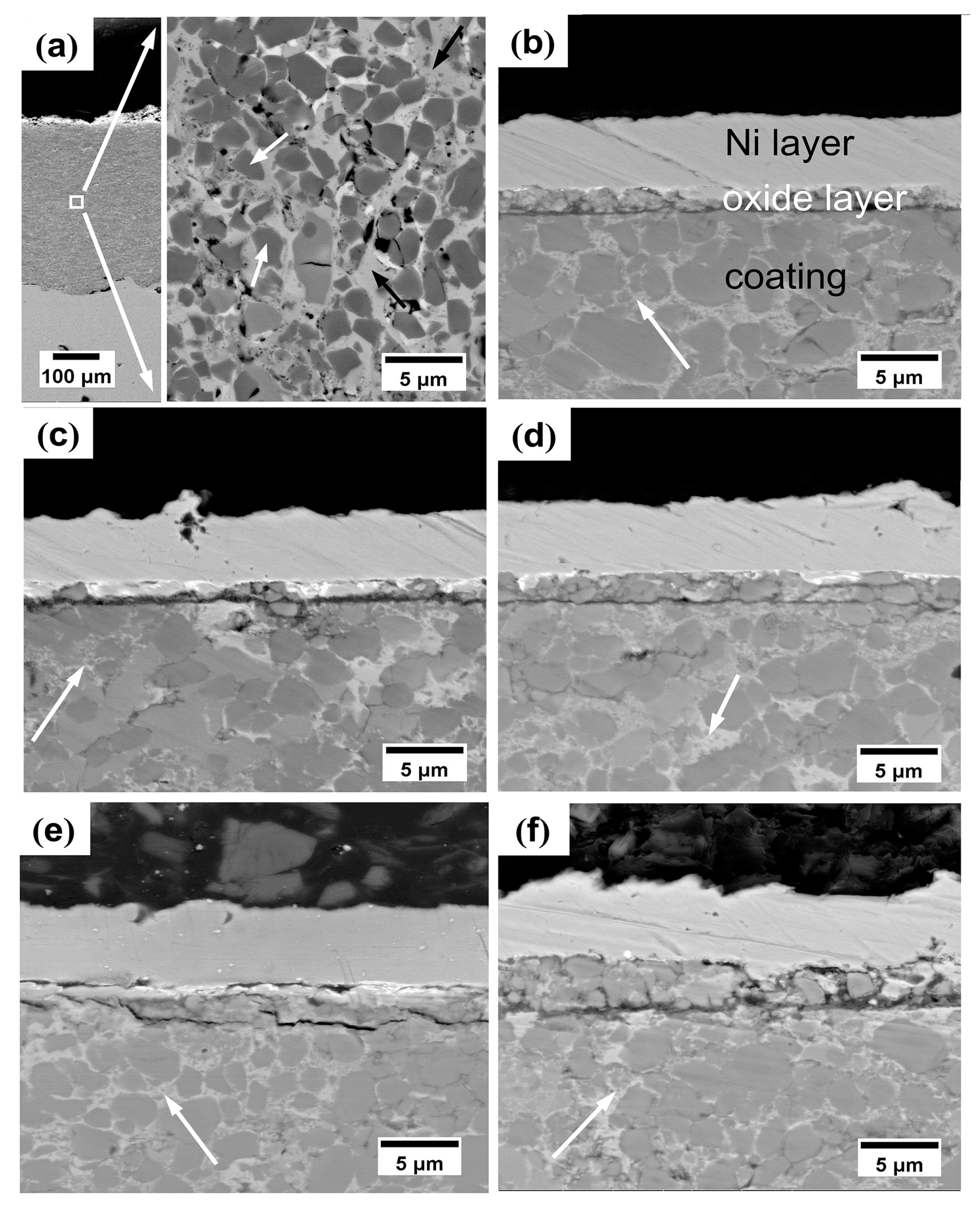
3.1.2. Microstructure Analysis

Figure 3a shows the cross-sectional BSE image of the as-sprayed coating before surface polish. The coating is dense and ~370 μm in thickness. Porosity calculated from image analysis is 2.2% ± 0.4%. An expanded view of the as-sprayed coating is also shown in Figure 3a, where two phases can be clearly identified by the image contrast. The light gray areas marked by black arrows are the Ni-rich binder phase, as later revealed by EDS analysis. Variation of greyscale of the Ni-rich phase can be observed, which may be attributed to a small amount of carbide dissolution. The dark gray particles surrounded by the NiCr binder phase (indicated by the white arrows) are carbides. Some pores are also spotted (black). No internal oxides are detected in the as-sprayed coating.
Microstructural evolution of the coating after annealing at 600 °C for various holding time is exhibited in Figure 3b–f. One prominent feature of the annealed coating is the presence of fine, secondary carbide particles precipitated from the NiCr binder (marked by white arrows). Most importantly, an oxide scale consists of Cr2O3 is formed on the top surface of the coating after annealing and the scale thickness increases with increasing annealing time. The cracks at the oxide/coating interface were induced by sectioning and mounting during SEM preparation as no spallation was observed on the surface of the annealed coating. In Figure 4a,b, the oxide-scale thickness (h) is plotted as a function of annealing time (t) and square root of time (t0.5), respectively. The oxide-scale growth kinetics obeys the parabolic law that a linear relationship can be observed on the h-t0.5 relationship, suggesting a diffusion-controlled growth mechanism. The growth rate, kp, calculated from the linear fitting of h-t0.5 relationship, is 1.17 × 10⁻¹² cm2·s−1.
Figure 5 shows the surface morphology of the oxide scale (before depositing the Ni protection layer), where an increase in the surface roughness can be observed with increasing annealing time. For example, after annealing for 6 h, the surface is smooth and a slight contrast difference can be observed, which suggests that the oxide-scale is thin to present the two-phase structure of the underlying coating. Under secondary electron (SE) mode, the brightness contrast indicates a difference in height. The bright regions exhibit a higher altitude than the dark regions, suggesting two different ways of oxides growth, namely the outward diffusion of Cr for the NiCr binder phase and the inward diffusion of oxygen for the carbides. However, with increasing annealing time, e.g., 192 and 384 h, the surface shows homogeneous and dense structure with presence of large particles, indicating the formation of a dense and continuous oxide-scale with certain thickness. EDS point analysis (not shown) reveals that the lager particles on the coating surface after 384 h annealing are rich in Cr and O.

3.2. Hardness and Tribological Properties

3.2.1. Hardness of the Annealed Coatings

Effect of high-temperature annealing on the surface hardness is presented in Figure 6. The as-sprayed coating has a hardness of 970 ± 25 kgf·mm−2, which increases rapidly to 1087 ± 35 kgf·mm−2 after 6 h annealing due to formation of the Cr2O3 layer. With increasing annealing time, the surface hardness shows a small variation within a certain deviation up to 192 h. The surface hardness of the 384 h-annealed coating reaches a maximum value ~1250 kgf·mm−2, which is ~128% of the as-sprayed coating.

3.2.2. Friction Coefficient and Wear Rate

Figure 7a presents the coefficient of friction (CoF) of the as-sprayed and the annealed coatings versus the Si3N4 ball at both RT and HT. The as-sprayed coating shows a mean CoF of 0.62 at RT, which decreases slightly to 0.59 after annealing for 192 h due to formation of the oxide scale [32]. At 600 °C, the mean values of CoF decrease to 0.46–0.51 for all the coatings. The lower CoF value at HT than at RT suggests that the compacted oxides debris have formed a tribo-oxide layer on the wear track to serve as lubricant. This oxide-based tribo-layer is responsible for the decreased CoF due to its low shear strength [33].
Wear rates of the as-sprayed and the annealed coatings versus Si3N4 ball at RT and 600 °C are presented in Figure 7b. At RT, the as-sprayed coating shows a wear rate of ~2.5 × 10⁻⁶ mm3·N−1·m−1 and the 192 h-annealed coating presents a slightly lower wear rate but still in the same magnitude. These values are comparable with those reported in literature [34,35]. At 600 °C, the wear rates of all the coatings are an order of magnitude higher than the RT values. Furthermore, the wear rate shows a decreasing trend with increasing annealing time. Thus, it is reasonable to conclude that formation of oxide is beneficial for coatings to resist sliding wear damage.

3.3. Characterization of the Wear Scar

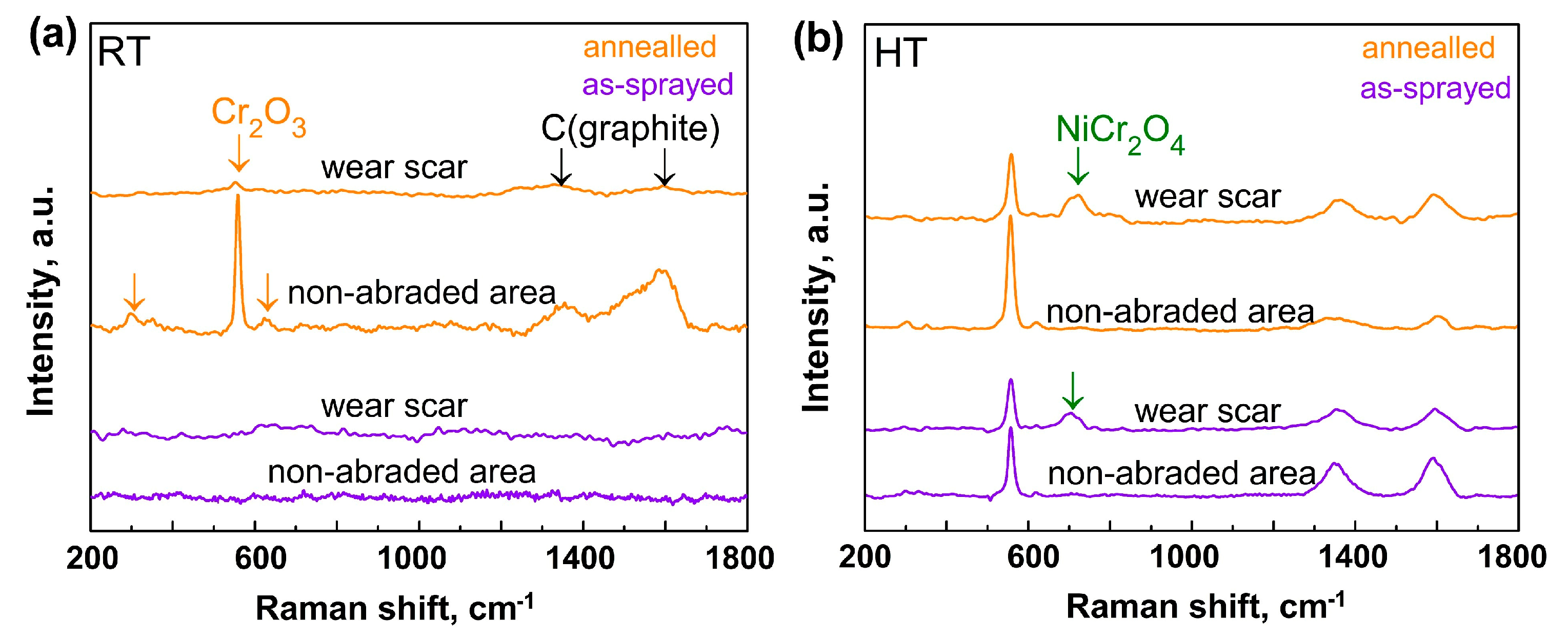
3.3.1. Raman Spectroscopy Analysis

To identify the compositional change after wear tests at RT and 600 °C, Raman spectra were collected from the wear scars and compared with those from non-abraded areas. Figure 8a shows the Raman spectra of the as-sprayed and the annealed coatings after wear tests at RT. The as-sprayed coating shows no Raman signal both on the wear scar and non-abraded area. For the annealed coating, the wear scar area shows weak peaks corresponding to Cr2O3 and graphitic carbon. Compared to the non-abraded area, the peak intensities are significantly reduced due to partial damage of the oxide scale. After wear tests at HT, as shown in Figure 8b, the wear scar areas of the as-sprayed and the annealed coatings not only retain the mean peaks of Cr2O3 and carbon, but also present an additional, broad peak at 700 cm−1 corresponding to a poorly crystalline spinel oxide NiCr2O4 [36,37]. During the sliding wear test, the original oxide scale was removed to expose the underlying fresh surface. Ni in the binder phase was rapidly oxidized to NiO, and subsequently reacted with Cr2O3 to form NiCr2O4. Combing the results from Figure 8a,b, the following information can be drawn: (1) The as-sprayed and the annealed Cr3C2-NiCr coatings have different wear behaviors at RT and at HT. Test temperature is critical to the wear mechanism; (2) At HT, new oxide (NiCr2O4) is formed on the wear scar region, suggesting a frictional heat at the contact surface is also crucial to the tribo-oxidation during HT wear.

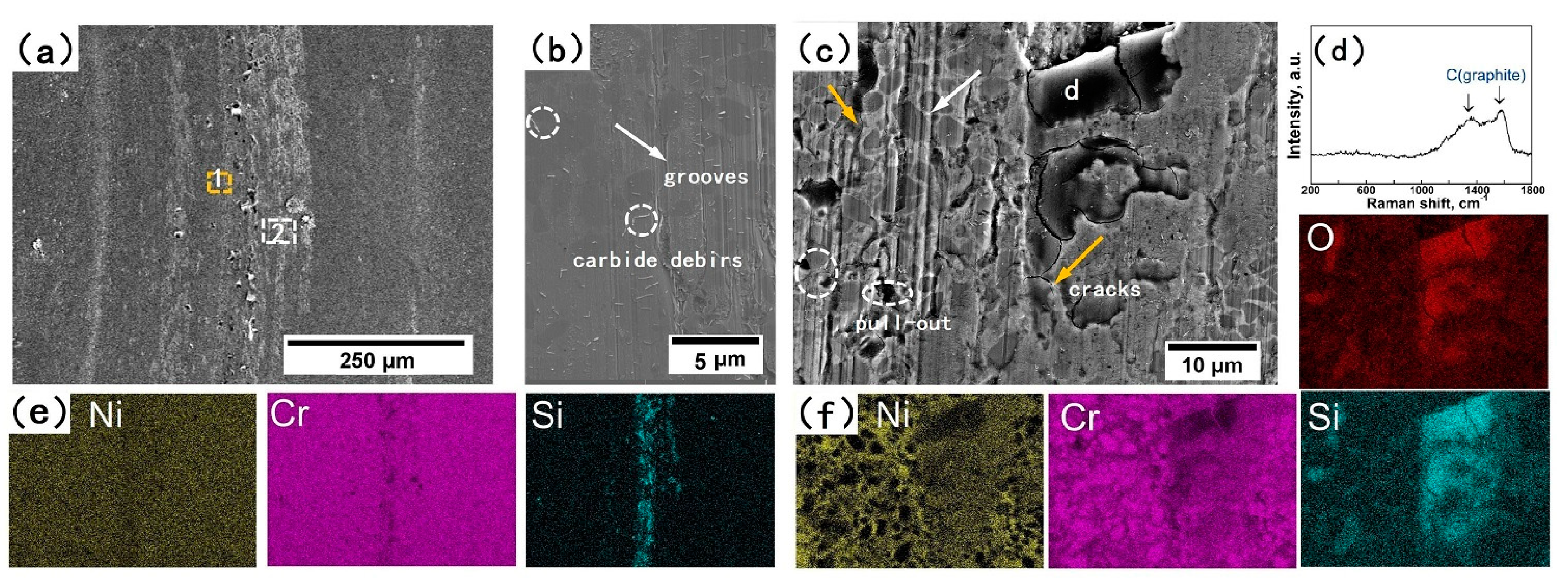
3.3.2. Surface Morphology of the Wear Scar

Figure 9 shows the morphology and the corresponding element mapping of the worn surface of the as-sprayed coating after RT wear test. During friction and wear tests, the softer binder phase is preferentially worn out, and the hard carbides protrude from the coating surface [38]. Cracks (orange arrows in Figure 9c) and pull-out of carbides (ellipse in Figure 9c) caused by normal pressure and friction, causing some Cr3C2 debris (circles in Figure 9b). Under the applied load in the abrasion test, hard particles (Cr3C2) slide along the contact surfaces and thus leave a large number of grooves (as pointed by white arrows in the high-magnification image in Figure 9b,c). These features indicate that the RT wear behavior is dominated by abrasive wear [39]. EDS element mapping in Figure 9c shows Si-rich and O-rich regions with a certain amount of Ni and Cr, resulting from the localized friction heat. Raman analysis of area d (Figure 9d) shows two typical peaks for graphite without signals for Cr, Ni or Si oxides. Figure 10 shows the morphology of the worn surface of the 192 h-annealed coating. Abrasion only occurs at the center of the wear scar (Figure 10c), but grooves are not as severe as those in Figure 9c. Other areas are covered with broken and deformed oxide scales without abrasion features (Figure 10b), indicating that the broken oxide scales can still protect the coating from abrasive wear.
Figure 11 shows the morphology and the corresponding element mapping of the worn surface of the as-sprayed coating after wear test at 600 °C. Compared with coatings after RT wear test, the surface morphology after HT wear test shows a smaller number of slight grooves and a smoother worn surface. And no particles fracture or cracks are observed (Figure 11b). EDS mapping (Figure 11c) shows homogenous distribution of Cr, Ni and Si on the wear scar despite of a higher oxygen concentration in the wear scar than the non-abraded region. This confirms a severe tribo-oxidation due to a high flash temperature at the contact surface [33]. The change from abrasive wear at RT to oxidation-dominated wear at HT results to the higher wear rates (Figure 7b).

3.3.3. Cross-Sectional Analysis of Wear Scar

Figure 12 shows the depth profile and the cross-sectional morphology of the wear scars of the as-sprayed and the annealed coatings after wear tests at 600 °C. The depth profiles in Figure 12a,c show that the wear scar of the as-sprayed coating is ~700 μm in length and ~10 μm in depth in comparison with ~530 μm and 8 μm for the annealed coating. This implies that the annealed coating has a better wear-resistance, which agrees with the lower wear rate as observed in Figure 7b.
Furthermore, the high-magnification cross-sectional image shows that the tribo-oxide layer of the as-sprayed coating is discontinuous with a thickness less than 1.0 μm (Figure 12b). In contrast, the tribo-oxide layer of the 192 h-annealed coating is ~1.6 μm in thickness and exhibits denser and more continuous microstructure (Figure 12d). Some cracks can be observed at the tribo-oxide layer, as indicated by the black arrows in Figure 12d. Severe cracking from surface to substrate beneath the wear scar as previously reported in [32] is not observed here and annealed coating.

4. Discussion

4.1. Microstructure and Composition Evolution of Coatings

The as-sprayed coating is composed of Cr3C2 particles exhibiting a dark grey contrast on BSE micrographs and Ni-rich binder phase which shows as (varying) light gray matrix (Figure 3). Such a typical microstructure feature implies the dissolution of certain amount of C and Cr into the binder phase. This is associated with the high temperature jet flame during the HVAF process, which can partially or fully melt Ni(Cr) (melting point ~1430 °C [40]). Therefore, Cr3C2 particles are surrounded by molten Ni(Cr) and some particles dissolve into it. According to the phase diagram of Cr–Ni–C introduced by Velikanova et al. [40], a liquid phase should present at the interface of Cr3C2 and Ni(Cr) because of an eutectic reaction between solid solution Ni(Cr) and Cr3C2 at ~1249 °C. The reaction can be expressed as:
Cr 3 C 2 +   Ni ( Cr )     L
This results in more carbide dissolution into the Ni(Cr) phase to form a supersaturated Ni(Cr,C) solid solution during spraying. Similar results are also reported in [27]. The supersaturated Ni(Cr,C) solid solution can be retained when it hits the stainless substrate due to rapid cooling. The above process results in the complex microstructure, i.e., non-equilibrium phase (Figure 2), varying contrast scale (Figure 3) and different carbides content, of the as-sprayed coating.
During long-term exposure at 600 °C in air, the Ni-rich region supersaturated with Cr and C is likely to decompose and yield fine Cr3C2 precipitates. The binder phase undergoes a transition from supersaturated, amorphous state to crystalline state [6,41,42,43]. Here we employ Rietveld refinement to quantify the weight fraction of the carbide and the binder phases. The oxide-scale is carefully removed from the coating to exclude the possible impact from the oxide layer. The fitting procedures are described in Supplementary Information with a typical fitting curve presented in Figure S2. Figure 12 shows the weight fraction of each phase as a function of annealing time, where an increase in the Cr3C2 phase and a corresponding drop in the NiCr binder phase can be observed with increasing annealing time until 96 h. With further increase in the annealing time, the weight fraction remains stable at 70.1 wt.% for the Cr3C2 phase and 27.6 wt.% for the NiCr binder phase. These values deviate from those for the original feedstock powders (indicated by the dashed lines), which may relate to the existence of residual amorphous Ni binder and (Cr,Ni)7C3 as reported in [6,27]. It should be mentioned that ~2.3 wt.% Cr2O3 can be also quantified in the annealed coatings, which may be caused by internal oxidation.
Furthermore, we also employ image analysis to quantify the volume fraction of Cr3C2 phase in both as-sprayed and annealed coatings. Variation of the volume fraction of the carbide phase as a function of annealing time is shown in Figure 13b. The carbide volume fraction is 55.4 ± 1.2 vol.% in the as-sprayed coating, which is significantly lower than the theoretical carbide fraction (~79–80 vol.% [27]). This is caused by dissolution of carbides into the molten binder phase during HVAF spraying, which is in line with previous studies [6,34,44]. After annealing, the volume fraction of carbide shows a rapid increase over the first 96 h. It is likely to be related to the precipitation of a large amount of fine scale carbides as observed in Figure 3. With further increase in annealing time, volume fraction of carbide reaches a steady state, indicating that precipitation of carbides is completed and the onset of carbides growth starts to dominate the process. The final carbide volume fraction is ~83.1 ± 3.0 vol.%, which is slightly higher than the theoretical value (79–80 vol.% [27]) due to difficulty in distinguishing dark contrast features (oxide or pore) from the gray contrast (carbides) in image analysis. Nevertheless, the fraction variation of the carbide phase from Rietveld refinement and image analysis shows the same variation with increasing annealing time.

4.2. Wear Mechanism(s) of Coatings at RT and HT

Results in Figure 7b show that the annealed coatings have lower wear rates at both RT and HT. The improved wear resistance of the annealed coatings can be attributed to (1) formation of the Cr2O3 oxide scale and (2) increase in the volume fraction of carbides. In detail, Cr2O3 is reported with good tribological properties, such as high hardness and high resistance to microcracks and particle fractures [45]. The mechanical properties of the oxide scale, such as hardness, fracture toughness and adhesion with substrate, will affect the effectiveness of oxide scale as a protective layer [46]. Thus, a continuous and dense oxide-scale covered the coating surface is beneficial to reducing the wear rate.
Moreover, it should be mentioned that the depth of wear scar is larger than the oxide-scale thickness (>10 μm vs. <3.5 μm). During wear tests, the oxide scale is partially removed by the hard Si3N4 counterpart ball, therefore, the contact surface between the coating and the Si3N4 also plays a critical role to the wear behavior. With increasing annealing time, the increased volume fraction of carbides results to a smaller contact area between the soft binder and the hard asperities/wear debris, which not only protects the softer binder from wear, but also decreases abrasion of carbide particles (as shown in Figure 10). Thus, the increased carbides volume fraction may, to a certain degree, contribute to the enhanced wear resistance of coatings as also reported in [47,48].
The above analysis suggests that the improved wear resistance of annealed coatings is a combined effect from both the oxide-scale and the carbides in the underlying coatings. Based on the above discussion, we propose a model to describe the wear mechanism of the annealed coatings at RT and HT, as shown in Figure 14. At RT, both as-sprayed and annealed coatings experience grooving and scratching by carbides particles. But the abrasive wear is much severer, and debris adhesion simultaneously occur on the wear scar. For the annealed coating, the existing oxide-scale is partially removed by smearing and shearing due to hard asperities or carbides debris. Furthermore, the heat generated by friction is insufficient to form any new tribo-oxide layer. However, the residual oxides are compacted to cover the partially worn surface to protect the coating from further damage.
At HT, after removal of the oxide-scale the fresh surface of the underlying coating experiences a rapid re-oxidation to form new oxides, which are removed again and smeared along the contact surface. The cycle of re-growth and removal of oxides may last for a period until oxide debris are compacted to form a tribo-oxide layer, which can further protect the subsurface from abrasion and microcracks. It can be predicted that if oxide debris are sufficient to form a compacted tribo-layer quickly before the original oxide layer is broken, the only abraded material will be the oxide-based tribo-layer. The wear behavior at HT can be therefore described by an oxidation-dominated mechanism, as illustrated in Figure 14. For the as-sprayed coating, the wear behavior is similar to that of the annealed coating except for the thinner tribo-oxide layer.

5. Conclusions

In this work, Cr3C2-25NiCr coatings were deposited on stainless steel substrates by HVAF. The wear behaviors of as-sprayed and annealed coatings were investigated both at RT and 600 °C. The most important finding is that annealing at 600 °C in air is effective to enhance the wear resistance of the coating both at RT and HT due to a combined effect from the formation of oxide-scale on the coating surface and the increase in the volume fraction of carbide in the coating. The wear behavior of the annealed coatings is discussed from the oxide growth and the microstructural evolution of the coatings and models to describe the wear mechanism at RT and at HT are proposed. Summary of the main conclusions is listed below:
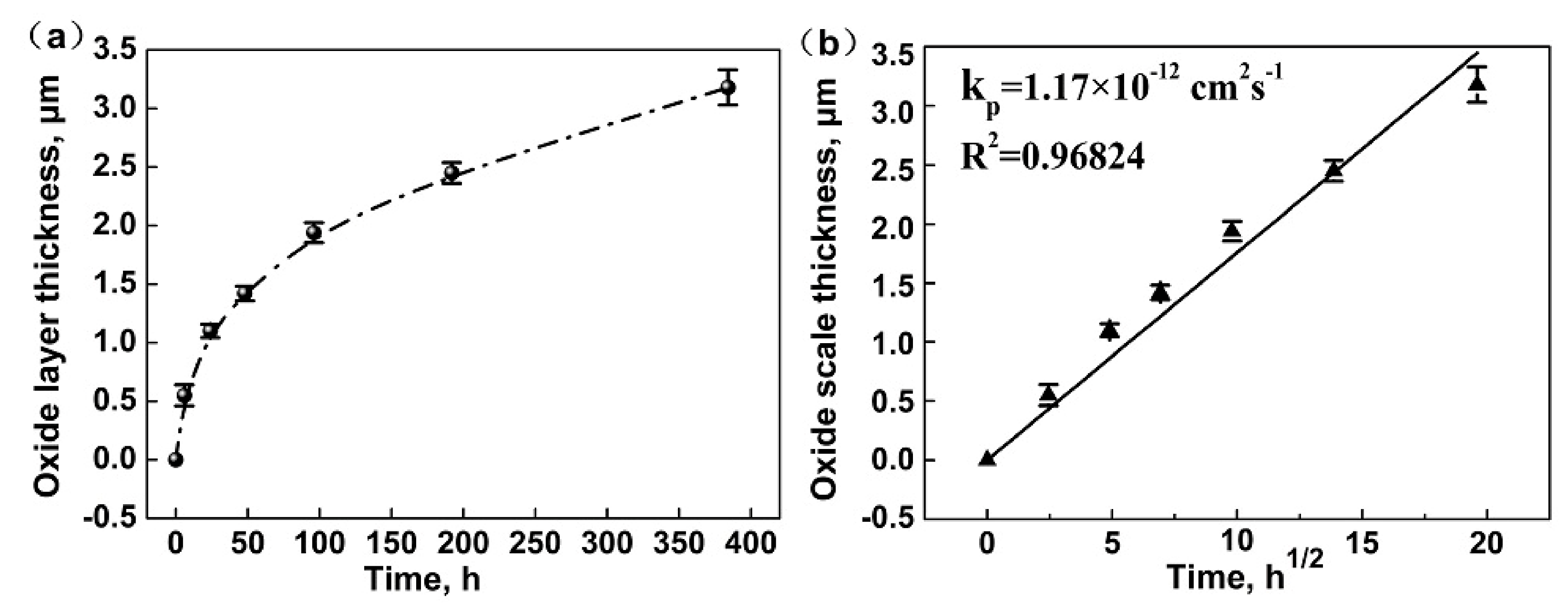
  • The as-sprayed Cr3C2-NiCr coating is subjected to oxidation at 600 °C in air to form a continuous and dense Cr2O3 oxide scale on the coating surface. The oxide-scale growth follows the parabolic law that the thickness increases linearly with increasing square root of annealing time. The underlying coating experiences a compositional variation during annealing. The volume fraction of the carbide phase shows a rapid increase up to 96 h annealing and then remains stable.
  • The annealed coatings show better wear-resistance than the as-sprayed coating both at RT and at HT due to a combined effect from the formation of oxide-scale and the increased carbide fraction in the coatings after annealing.
  • The wear behaviors of the annealed coatings obey different mechanisms at RT and HT. The RT wear behavior follows an abrasive wear mechanism, whereas the HT wear behavior is best described by an oxidative wear, in which formation of a tribo-oxide layer plays a critical role to reduce the friction coefficient and to protect the underlying coatings from damage.
The findings of this work reveal the significance of oxide-scale growth and microstructural evolution on the HT wear behaviors of the Cr3C2-25NiCr coating, which provides strategies for enhancing the wear properties of such coatings for HT applications.

Supplementary Materials

The following are available online at https://www.mdpi.com/2079-6412/10/11/1090/s1, Figure S1: (a) SEM micrograph and (b) XRD pattern of the feedstock powder used for HVAF, Figure S2: Rietveld refinement of the XRD pattern of the 192 h-annealed coating after removal the oxide-scale.

Author Contributions

Investigation, X.L.; Writing—original draft preparation, X.L.; Writing—review and editing, F.Y.; Supervision, X.Z. and F.Y. All authors have read and agreed to the published version of the manuscript.

Funding

This research was funded by National Natural Science and Foundation of China, grant number 51971139.

Conflicts of Interest

The authors declare no conflict of interest.

References

  1. Matthews, S.; James, B.; Hyland, M. The role of microstructure in the high temperature oxidation mechanism of Cr3C2-NiCr composite coating. Corros. Sci. 2009, 51, 1172–1180. [Google Scholar] [CrossRef]
  2. Matthews, S.; James, B.; Hyland, M. High temperature erosion−oxidation of Cr3C2-NiCr thermal spray coatings under simulated turbine conditions. Corros. Sci. 2013, 70, 203–211. [Google Scholar] [CrossRef]
  3. Ahuja, L.; Mudgal, D.; Singh, S.; Prakash, S. A comparative study to evaluate the corrosion performance of Zr incorporated Cr3C2-NiCr coating at 900 °C. Ceram. Int. 2018, 44, 6479–6492. [Google Scholar] [CrossRef]
  4. Matthews, S.; James, B.; Hyland, M. The effect of heat treatment of the oxidation mechanism of blended powder Cr3C2-NiCr coatings. J. Therm. Spray Technol. 2010, 19, 119–127. [Google Scholar] [CrossRef]
  5. Berger, L.-M. Application of hard metals as thermal spray coatings. Int. J. Refract. Met. Hard Mater. 2015, 49, 350–364. [Google Scholar] [CrossRef]
  6. Matthews, S.; Berger, L.-M. Long-term compositional/microstructural development of Cr3C2-NiCr coatings at 500 °C, 700 °C and 900 °C. Int. J. Refract. Met. Hard Mater. 2016, 59, 1–18. [Google Scholar] [CrossRef]
  7. Matthews, S.; Asadov, A.; Ruddell, S.; Berger, L.-M. Thermally induced metallurgical processes in Cr3C2-NiCr thermal spray coatings as a function of carbide dissolution. J. Alloys. Compd. 2017, 728, 445–463. [Google Scholar] [CrossRef]
  8. Matthews, S.; James, B.; Hyland, M. The role of microstructure in the high velocity erosion of Cr3C2-NiCr thermal spray coatings: Part 1-as-sprayed coatings. Surf. Coat. Technol. 2009, 203, 1086–1093. [Google Scholar] [CrossRef]
  9. Berger, L.-M.; Woydt, M.; Saaro, S. Comparison of self-mated hard metal coatings under dry sliding conditions up to 600 °C. Wear 2009, 266, 406–416. [Google Scholar] [CrossRef]
  10. Wang, Q.; Luo, S.; Wang, S.; Wang, H.; Ramachandran, C.S. Wear, erosion and corrosion resistance of HVOF-sprayed WC and Cr3C2 based coatings for electrolytic hard chrome replacement. Int. J. Refract. Met. Hard Mater. 2019, 81, 242–252. [Google Scholar] [CrossRef]
  11. Bjordal, M.; Bardal, E.; Rogne, T.; Eggen, T.G. Combined erosion and corrosion of thermal sprayed WC and CrC coatings. Surf. Coat. Technol. 1995, 70, 215–220. [Google Scholar] [CrossRef]
  12. Wirojanupatump, S.; Shipway, P.H.; McCartney, D.G. The influence of HVOF powder feedstock characteristics on the abrasive wear behaviour of CrxCy-NiCr Coatings. Wear 2001, 249, 829–837. [Google Scholar] [CrossRef]
  13. Vashishtha, N.; Sapate, S.G.; Bagde, P.; Rathod, A.B. Effect of heat treatment on friction and abrasive wear behaviour of WC-12Co and Cr3C2-25NiCr coatings. Tribo. Int. 2018, 118, 381–399. [Google Scholar] [CrossRef]
  14. Guilemany, J.M.; Miguel, J.M.; Vizcaíno, S.; Lorenzana, C.; Delgado, J.; Sánchez, J. Role of heat treatments in the improvement of the sliding wear properties of Cr3C2-NiCr coatings. Surf. Coat. Technol. 2002, 157, 207–213. [Google Scholar] [CrossRef]
  15. Janka, L.; Norpoth, J.; Trache, R.; Berger, L.-M. Influence of heat treatment on the abrasive wear resistance of a Cr3C2-NiCr coating deposited by an ethane-fuelled HVOF spray process. Surf. Coat. Technol. 2016, 291, 444–451. [Google Scholar] [CrossRef]
  16. Gariboldi, E.; Rovatti, L.; Lecis, N.; Mondora, L.; Mondora, G.A. Tribological and mechanical behaviour of Cr3C2-NiCr thermally sprayed coatings after prolonged aging. Surf. Coat. Technol. 2016, 305, 83–92. [Google Scholar] [CrossRef]
  17. Janka, L.; Norpoth, J.; Trache, R.; Thiele, S.; Berger, L.-M. HVOF- and HVAF- sprayed Cr3C2-NiCr coatings deposited from feedstock powders of spherical morphology: Microstructure formation and high-stress abrasive wear resistance up to 800 °C. J. Therm. Spray Technol. 2017, 26, 1720–1731. [Google Scholar] [CrossRef]
  18. Kamali, R.; Binesh, A.R. The importance of sensitive parameters effect on the combustion in a high velocity oxygen-fuel spray system. Int. J. Heat Mass Transf. 2009, 36, 978–983. [Google Scholar] [CrossRef]
  19. Guo, X.; Planche, M.P.; Chen, J.; Liao, H. Relationships between in-flight particle characteristics and properties of HVOF sprayed WC-CoCr coatings. J. Mater. Process Technol. 2014, 214, 456–461. [Google Scholar] [CrossRef]
  20. Souza, V.A.D.; Neville, A. Mechanisms and kinetics of WC-CoCr high velocity oxy-fuel thermal spray coating degradation in corrosive environments. J. Therm. Spray Technol. 2006, 15, 106–117. [Google Scholar] [CrossRef]
  21. Matthews, S.; James, B. Review of thermal spray coating applications in steel industry: Part 2-zinc pot hardware in the continuous galvanizing line. J. Therm. Spray Technol. 2010, 19, 1277–1286. [Google Scholar] [CrossRef]
  22. Varis, T.; Suhonen, T.; Ghabchi, A.; Valarezo, A.; Sampath, S.; Liu, X.; Hannula, S.-P. Formation mechanisms, structure, and properties of HVOF-sprayed WC-CoCr coatings: An approach toward process maps. J. Therm. Spray Technol. 2014, 23, 1009–1018. [Google Scholar] [CrossRef]
  23. Bolelli, G.; Berger, L.-M.; Börner, T.; Koivuluoto, H.; Lusvarghi, L.; Lyphout, C.; Markocsan, N.; Matikainen, V.; Nylén, P.; Sassatelli, P.; et al. Tribology of HVOF- and HVAF-sprayed WC-10Co4Cr hardmetal coatings: A comparative assessment. Surf. Coat. Technol. 2015, 265, 125–144. [Google Scholar] [CrossRef]
  24. Ang, A.S.M.; Howse, H.; Wade, S.A.; Berndt, C.C. Development of processing windows for HVOF carbide-based coatings. J. Therm. Spray Technol. 2016, 25, 28–35. [Google Scholar] [CrossRef]
  25. Li, C.J.; Ji, G.C.; Wang, Y.Y.; Sonoya, K. Dominant effect of carbide rebounding on the carbon loss during high velocity oxy-fuel spraying of Cr3C2-NiCr. Thin Solid Films 2002, 419, 137–143. [Google Scholar] [CrossRef]
  26. Hou, G.; An, Y.; Zhao, X.; Zhou, H.; Chen, J. Effect of alumina dispersion on oxidation behavior as well as friction and wear behavior of HVOF-sprayed CoCrAlYTaCSi coating at elevated temperature up to 1000 °C. Acta Mater. 2015, 95, 164–175. [Google Scholar] [CrossRef]
  27. Ding, Y.; Hussain, T.; McCartney, D.G. High-temperature oxidation of HVOF thermally sprayed NiCr-Cr3C2 coatings: Microstructure and kinetics. J. Mater. Sci. 2015, 50, 6808–6821. [Google Scholar] [CrossRef]
  28. Mougin, J.; Le Bihan, T.; Lucazeau, G. High-pressure study of Cr2O3 obtained by high-temperature oxidation by X-ray diffraction and Raman spectroscopy. J. Phys. Chem. Solids 2001, 62, 553–563. [Google Scholar] [CrossRef]
  29. Shim, S.H.; Duffy, T.S.; Jeanloz, R.; Yoo, C.S.; Iota, V. Raman spectroscopy and X-ray diffraction of phase transitions in Cr2O3 to 61 GPa. Phys. Rev. B 2004, 69, 1124–1133. [Google Scholar] [CrossRef] [Green Version]
  30. Nakamura, K.; Fujitsuka, M.; Kitajima, M. Disorder-induced line broadening in first order Raman scattering from graphite. Phys. Rev. B 1990, 41, 12260–12263. [Google Scholar] [CrossRef]
  31. Matthews, S.; Berger, L.-M. Inter-diffusion between thermally sprayed Cr3C2-NiCr coatings and an Alloy 625 substrate during long-term exposure at 500°C, 700°C and 900°C. J. Alloys. Compd. 2019, 770, 1078–1099. [Google Scholar] [CrossRef]
  32. Wang, H.; Yan, X.; Zhang, H.; Gee, M.; Zhao, C.; Liu, X.; Song, X. Oxidation-dominated wear behaviors of carbide-based cermets: A comparison between WC-WB-Co and Cr3C2-NiCr coatings. Ceram. Int. 2019, 45, 21293–21307. [Google Scholar] [CrossRef]
  33. Vashishtha, N.; Sapate, S.G.; Sahariah, B.J.; Bagde, P. Microstructural characterization and wear behaviour of high velocity oxy-fuel sprayed Cr3C2-25NiCr coating. Mater. Today Proc. 2018, 5, 17686–17693. [Google Scholar] [CrossRef]
  34. Matikainen, V.; Bolelli, G.; Koivuluoto, H.; Sassatelli, P.; Lusvarghi, L.; Vuoristo, P. Sliding wear behaviour of HVOF and HVAF sprayed Cr3C2-based coatings. Wear 2017, 388–389, 57–71. [Google Scholar] [CrossRef]
  35. Liu, X.B.; Liu, H.Q.; Liu, Y.F.; He, X.M.; Sun, C.F.; Wang, M.D.; Yang, H.B.; Qi, L.H. Effects of temperature and normal load on tribological behavior of nickel-based high temperature self-lubricating wear-resistant composite coating. Compos. Part B 2013, 53, 347–354. [Google Scholar] [CrossRef]
  36. Bolelli, G.; Berger, L.-M.; Börner, T.; Koivuluoto, H.; Matikainen, V.; Lusvarghi, L.; Lyphout, C.; Markocsan, N.; Nylén, P.; Sassatelli, P.; et al. Sliding and abrasive wear behaviour of HVOF-and HVAF-sprayed Cr3C2-NiCr hardmetal coatings. Wear 2016, 358, 32–50. [Google Scholar] [CrossRef]
  37. Hosterman, B.D.; Farley, J.W.; Johnson, A.L. Spectroscopic study of the vibrational modes of magnesium nickel chromite MgxNi1−xCr2O4. J. Phys. Chem. Solids 2013, 74, 985–990. [Google Scholar] [CrossRef]
  38. Lin, L.; Li, G.L.; Wang, H.D.; Kang, J.J.; Xu, Z.L.; Wang, H.J. Structure and wear behavior of NiCr-Cr3C2 coatings sprayed by supersonic plasma spraying and high velocity oxy-fuel technologies. Appl. Surf. Sci. 2015, 356, 383–390. [Google Scholar] [CrossRef]
  39. Hutchings, I.; Shipway, P. Wear by hard particles. In Tribology, 2nd ed.; Butterworth-Heinemann Elsevier Ltd.: Oxford, UK, 2017; pp. 165–166. [Google Scholar]
  40. Velikanova, T.Y.; Bondar, A.A.; Grytsiv, A.V. The chromium-nickel-carbon (Cr–Ni–C) phase diagram. J. Phase Equilib. 1999, 20, 125–146. [Google Scholar] [CrossRef]
  41. Poirier, D.; Legoux, J.-G.; Lima, R. Engineering HVOF-sprayed Cr3C2-NiCr coatings: The effect of particle morphology and spraying parameters on the microstructure, properties and high temperature wear performance. J. Therm. Spray Technol. 2013, 22, 280–289. [Google Scholar] [CrossRef]
  42. Murthy, J.K.N.; Satya Prasad, K.; Gopinath, K.; Venkataraman, B. Characterisation of HVOF sprayed Cr3C2-50(Ni20Cr) coating and the influence of binder properties on solid particle erosion behaviour. Surf. Coat. Technol. 2010, 204, 3975–3985. [Google Scholar] [CrossRef]
  43. Matthews, S. Development of high carbide dissolution/low carbon loss Cr3C2-NiCr coatings by shrouded plasma spraying. Surf. Coat. Technol. 2014, 258, 886–900. [Google Scholar] [CrossRef]
  44. Matikainen, V.; Bolelli, G.; Koivuluoto, H.; Honkanen, M.; Vippola, M.; Lusvarghi, L.; Vuoristo, P. A study of Cr3C2-based HVOF- and HVAF-sprayed coatings: Microstructure and carbide retention. J. Therm. Spray Technol. 2017, 26, 1239–1256. [Google Scholar] [CrossRef]
  45. Li, J.; Zhang, Y.; Huang, J.; Ding, C. Mechanical and tribological properties of plasma-sprayed Cr3C2-NiCr, WC-Co, and Cr2O3 coatings. J. Therm. Spray Technol. 1998, 7, 242–246. [Google Scholar]
  46. Nicholls, J.R.; Wellman, R.G. Oxidative wear. In Handbook of Lubrication and Tribology: Theory and Design; Bruce, R.W., Ed.; CRC Press: Boca Raton, FL, USA, 2012; pp. 1–24. [Google Scholar]
  47. Liu, Q.; Bai, Y.; Wang, H.D.; Ma, G.Z.; Liu, M.; Chu, C.Y. Microstructural evolution of carbides and its effect on tribological properties of SAPS or HVOF sprayed NiCr-Cr3C2 coatings. J. Alloys Compd. 2019, 803, 730–741. [Google Scholar] [CrossRef]
  48. Zafar, S.; Sharma, A.K. Microstructure and wear performance of heat-treated WC-12Co microwave clad. Vacuum 2016, 131, 213–222. [Google Scholar] [CrossRef]
Figure 1. (a) Schematic diagram of the ball-on-disc high-temperature testing equipment and (b) cross-sectional profile of a wear scar.
Coatings 10 01090 g001
Figure 2. (a) X-ray diffraction patterns and (b) Raman spectra collected from top surfaces of as-sprayed and annealed coatings.
Coatings 10 01090 g002
Figure 3. (a) Cross-sectional microstructure of the as-sprayed coating; (bf) cross-sectional SEM images of the coatings after annealing at 600 °C for 24, 48, 96, 192 and 384 h, respectively. The white arrows in (bf) indicate the precipitation of secondary carbide particles.
Coatings 10 01090 g003
Figure 4. Oxides scale thickness as a function of (a) annealing time and (b) square root of annealing time.
Coatings 10 01090 g004
Figure 5. Surface morphology of the oxide scale after annealing at 600 °C for 6, 24, 48, 96, 192 and 384 h.
Coatings 10 01090 g005
Figure 6. Surface hardness of the as-sprayed and the annealed coatings measured at RT.
Coatings 10 01090 g006
Figure 7. (a) COF and (b) wear rate of the as-sprayed and the annealed coatings versus Si3N4 at RT and at 600 °C. AS stands for as-sprayed coating without heat treatment.
Coatings 10 01090 g007
Figure 8. Raman spectra of the wear scar and the non-abraded regions of the as-sprayed and the annealed coatings after wear tests at (a) RT and (b) 600 °C. The annealed coatings with different holding times show similar features before and after wear tests, therefore only the 192 h-annealed coating is presented here as a representative.
Coatings 10 01090 g008
Figure 9. (a) Surface morphology of the wear scar of the as-sprayed coating after wear test at RT; (b,c), high-magnification images of the selected regions marked by 1,2 in (a); (d) Raman Spectrum of the selected area in (c); (e) EDS elemental mapping of Ni, Cr and Si of (a); (f) EDS elemental mapping of Ni, Cr, O and Si of (c).
Coatings 10 01090 g009
Figure 10. (a) Surface morphology of the 192 h-annealed coating after wear test at RT; (b,c), high-magnification images of the selected regions marked by 3,4 in (a); (d) EDS elemental mapping of Ni, Cr, Si, C and O of (a).
Coatings 10 01090 g010
Figure 11. (a) Surface morphology of the wear scar (the region between two dash lines) of the as-sprayed coating after wear test at 600 °C; (b) high-magnification image of the selected region marked by the dashed rectangle in (a); (c) EDS elemental mapping of Cr, Ni, O and Si of (a).
Coatings 10 01090 g011
Figure 12. (a) Depth profile and (b) cross-sectional SEM image of the wear scar of the as-sprayed coating after HT wear test, (c,d) those of the 192 h-annealed coating. The black arrow in (d) points out a crack.
Coatings 10 01090 g012
Figure 13. (a) Weight fraction of the Cr3C2 and the NiCr binder phase as a function of annealing time obtained from Rietveld refinements; (b) variation of the volume fraction of Cr3C2 with annealing time calculated from image analysis.
Coatings 10 01090 g013
Figure 14. Schematic of wear mechanism of coatings at RT and at 600 °C.
Coatings 10 01090 g014
Table 1. Parameters used in the HVAF process.
ParametersValue
FuelPropane
Fuel pressure (kPa)579.2
Air pressure (kPa)606.8
H2 flow rate (Stard Liter Per Minute, SLPM)22
Carrier gas flow rate (N2, SLPM)23
Surface speed (mm·s−1)2000
Spray distance (mm)195
Powder feed rate (g·min−1)100–150
Publisher’s Note: MDPI stays neutral with regard to jurisdictional claims in published maps and institutional affiliations.

