Article

Performance of Cu–Ag Thin Films as Diffusion Barrier Layer

Department of Mechanical Engineering, National Cheng Kung University, Tainan 701, Taiwan
*
Author to whom correspondence should be addressed.
Coatings 2020, 10(11), 1087; https://doi.org/10.3390/coatings10111087
Submission received: 11 October 2020 / Revised: 7 November 2020 / Accepted: 11 November 2020 / Published: 13 November 2020

Abstract

:
It is well-known that Cu–Sn intermetallic compounds are easily produced during reflow process and result in poor reliability of solder bump. Recently, amorphous metallic films have been considered to be the most effective barrier layer because of the absence of grain boundaries and immiscibility with copper. Since Cu–Ag alloys are characterized by their lower electrical resistivity and superior glass-forming ability, they are appropriate to be used as the diffusion barrier layers. In this study, molecular dynamics simulation was performed to investigate the effects of composition ratio and quenching rate on the internal microstructure, diffusion properties, and the strength of the interface between polycrystalline Cu and Cu–Ag barrier layers. The results showed that Cu40Ag60 and Cu60Ag40 present more than 95% of the amorphous at quenching rate between 0.25 and 25 K/ps, indicating a good glass-forming ability. Diffusion simulation showed that a better barrier performance can be achieved with higher amorphous ratio. For the sample of Cu20Ag80 with quenching rate of 25 K/ps, a void is initially generated in amorphous Cu–Ag layer during the tensile test. This indicates the strength of amorphous Cu–Ag is weaker than Cu–Ag/Cu interface and the polycrystalline Cu layer.

1. Introduction

Recently, 2.5D integrated circuit (IC) flip chip assembly package with microbump was widely adopted in high-end niche applications [1]. In the meantime, copper is gradually replacing aluminum as a lead and trace material because of its much lower resistance. There are two basic solid state diffusion mechanisms: vacancy (substitutional diffusion) and interstitial diffusion. The major concern of using copper as metallization, however, is its much higher diffusion coefficient than aluminum due to smaller atomic size and lower activation energy [2,3]. Cu–Sn intermetallics compounds (IMCs) are easily formed by the reaction of copper and tin through diffusion effect even at temperature as low as 200 °C [4,5,6,7]. Generally, IMCs layer is the most brittle part in the solder joint and thus easily results in the failure of electronic devices during service. Hence, it is important to select a proper material as a diffusion barrier between copper and tin to prevent the formation of IMCs during the minimization progress of electronics devices. In the recent years, several kinds of materials, such as TiN [8,9,10,11], Ni [12,13,14], Ta [15], and amorphous Zr53Cu30Ni9Al8 [16], have been investigated as barrier layers to inhibit rapid copper diffusion in interconnect structures. Among these candidates, TiN, Ni, and Ta barrier layers are polycrystalline and cannot provide sufficient protection because grain boundaries can provide fast diffusion paths for copper and could react to form Cu–Sn IMCs. On the contrary, amorphous barrier layers exhibit superior behavior. These kinds of thin film metallic glasses (TFMGs) have been examined and regarded as the promising diffusion barriers in integrated circuits applications [17,18,19,20,21,22] because of the absence of grain boundaries and immiscibility with copper [23,24,25]. Amorphous coatings also can be utilized for the purpose of corrosion resistance [26,27]. Their mechanical properties and fracture mechanisms in nano-scale have been investigated [28,29].
Compared to Zr53Cu30Ni9Al8 alloy, Cu–Ag alloys exhibit much lower electrical resistivity [30,31] and superior glass-forming ability. Recently, it has been considered as the candidate material of interconnection in high-field magnets [32,33]. Cu–Ag alloys can also be used in modern ultra-large-scale-integration interconnect applications. Their reliability can be enhanced by low grain boundaries, low interface diffusion, low electrical resistivity, and high mechanical strength by adjusting the composition ratio [34,35]. As a potential material of TFMGs barrier layer, the diffusion behavior of Cu–Ag and strength of this layered structure are crucial and need further detailed investigation.

2. Materials and Methods

In this article, molecular dynamics (MD) simulation was adopted in analysis. The effects of composition ratio and quenching rate on the internal microstructure and diffusion properties of Cu–Ag alloy, as well as the strength of the barrier layer were systematically investigated. The large-scale atomic/molecular massively parallel simulator (LAMMPS, The large-scale atomic/molecular massively parallel simulator, version 27 Nov. 2018, Sandia National Laboratories, Albuquerque, NM, USA) [36] and the package of open visualization tool (OVITO, open visualization tool, version 2.9.0 (27 July 2017), Technical University of Darmstadt, Darmstadt, Germany) [37] were individually adopted as the analysis software and the scientific visualization for atomistic simulation data. Moreover, the embedded-atom method (EAM) potential was adopted to model the atomistic interactions among Cu and Ag atoms [38,39]. This potential has been successfully applied to accurately simulate the structure, surface, and transformation of amorphous metallic materials.

2.1. Amorphous Geometry Structure

The amorphous structure of Cu–Ag at a temperature of 300 K was obtained by performing simulations with the following parameter settings and heat treatments. First, a crystal Cu–Ag alloy was created with a face-centered cubic copper lattice of 184,950 atoms and replaced enough copper atoms with silver to achieve the desired composition. Subsequently, a series of simulations of heat treatment was conducted within the isothermal isobaric ensemble (NPT) with an external pressure of zero. Three-dimensional periodic boundary conditions were applied to the simulation box. The velocities of atoms were adjusted in order to maintain them in an isothermal state with a specific temperature, obeying Newton’s second law. The model was initially relaxed under periodic boundary conditions at 300 K for 200 ps within a NPT ensemble. The system was heated from 300 to 2200 K at a constant heating rate of 5 × 10¹¹ to 5 × 10¹³ K/s, which produced a liquid phase. To make the state of the system as natural as possible, the liquid system was relaxed for 20 ps at 2200 K. Finally, the system was quenched from 2200 to 300 K at a quenching rate of 5 × 10¹³ K/s, followed by relaxation for 20 ps at 300 K. The amorphous alloy model, therefore, was prepared by performing the temperature history stages including heating state, holding state, and quenching state.

2.2. Procedures for Interface Model Preparation

The simulation box constructed in this work was a two-layered structure, composed of the layer of Cu–Ag alloys (after quenching) and Cu layer (polycrystalline). The sizes of the former are 30 nm × 30 nm × 5 nm in width (x-axis), height (z-axis), and thick (y-axis), respectively, while the latter is 30 nm × 10 nm × 5 nm in width (x-axis), height (z-axis), and thick (y-axis), respectively. These two layers were located together along the interfaces of the xy plane with a small separation distance of 3.5 Å based on the equilibrium bond lengths. After that, these two layers suddenly became in contact and bonded together automatically. It was reported that as long as the separation distance was appropriate, it did not affect the results [40].

2.3. Procedure for Diffusion and Deformation

Models of Cu/Cu–Ag layered structures were adopted for both of the diffusion and deformation simulations. In the model of deformation simulation, two additional rigid regions of dimensions 30 nm width (x-axis) × 5 nm height (y-axis) × 12 nm thick (z-axis) were imposed at the top and bottom sides of the model, respectively. A uniform velocity along z-axis direction in the opposite direction was individually applied to these two rigid regions, approximately equal to the strain rate of 1 × 10⁹ s−1. The condition of tensile test was simulated at a temperature of 300 K under NVT (constant-temperature and constant-volume) ensemble. Gear’s Predictor-Corrector integration algorithms [41] were adopted for the second-order differential equations of motion to correct all predicated positions. Moreover, a time step of 2 fs was selected.
To avoid the phenomena of steric clashes and the formation of inappropriate geometries, the established configuration of the system was relaxed by energy minimization first. The convergence of the pressure, temperature, potential energy, and volume as the function of time was achieved when the time is longer than 100 ps. In other words, it means the simulation model already reached steady state. To confirm the correctness of the intermolecular potential functions, Table 1 depicted the elastic constants of data by MD simulation and experiment, respectively [38,42]. Comparing the simulation data with experimental data, it was found that the errors between them were smaller than 2%, indicating the correctness of the potential functions. Since the elastic constants of Cu–Ag alloy are closely related to the ratio of composition, fabrication method, and microstructures, we did not find the elastic constants exactly equivalent to the microstructures of this study. However, it was reported in the literature [30] that the Young’s modulus of Cu20Ag80, prepared by co-sputtering technique, is around 95 GPa, in agreement with the data of 91.8 GPa (quenching rate 0.25 K/ps) of this study.
Some other verifications, such as atomic equilibrium distance, coefficient of thermal expansion, as well as glass transition temperature (Tg) are individually performed and discussed.
To analyze the thermodynamic properties of Cu–Ag alloys with four different compositions (Cu20Ag80, Cu40Ag60, Cu60Ag40, and Cu80Ag20) and three different quenching rates (0.25, 2.5, and 25 K/ps), the relationship between volume and temperature is compared in this section. Figure 1a,b shows the volume versus temperature curves of Cu20Ag80 and Cu40Ag60, respectively, at different quenching rates, which showed that glass transition temperature was dependent on the quenching rates. In order to acquire a more refined estimate of glass transition temperature, the data were captured with smaller increment in temperature, namely 1 K, from 2100 to 100 K. During the quenching process, the volume–temperature curves for Cu20Ag80 at a quenching rate of 0.25 K/ps, as shown in Figure 1a, indicate that the slope change in estimation takes place at about 550 K, which indicates that glass transition occurs near this temperature. These results were similar to the literature [43,44]. As shown in Figure 1, however, these curves are smooth for both Cu–Ag alloys at high quenching rates and are difficult to determine the glass transition temperature.

3. Results and Discussion

3.1. Radial Distribution Function (RDF)

To analyze the structural differences for different compositions and quenching rates, the RDF curves for all configurations were compared in this section. The results indicate that changes in quenching rates and different composition ratio have significant effects on the rearrangement of Cu–Ag alloy. The structure of Cu40Ag60 was studied at different quenching rates of 0.25, 2.5, and 25 K/ps to follow the evolution of the atomic arrangements during quenching, as shown in Figure 2a. The first peaks of Cu40Ag60 pair were at 0.279 nm with 300 K and 0.241 nm with 50 K. This result was in agreement with the results reported by Qi [43,44]. For the RDF curves of Cu60Ag40, the crystal peaks exceeding the second one gradually disappear, exhibiting a short-range ordered and long-range disordered feature. When the atomic ratio of Cu:Ag is close to 1:1, the first peak is wider (full widths at half maximum (FWHM) of Cu20Ag80, Cu40Ag60, Cu60Ag40 and Cu80Ag20 are about 0.7, 1.1, 1.0, and 0.9 nm, respectively) and the second and third peaks are merged together. This represents that the Cu40Ag60 and Cu60Ag40 have better glass-forming ability than Cu20Ag80 and Cu80Ag20 at the same quenching rate, as shown in Figure 2b.
Figure 3a–c individually shows the RDF curves of Cu–Cu, Ag–Ag, and Cu–Ag pairs of Cu40Ag60 as a function of temperature which drops from 1500 to 400 K under the quenching rate of 25 K/ps. It can be found from this figure that the second peaks of RDF curves become more explicit or splits as temperature decreases, which defines a common feature of the amorphous alloy. Therefore, the results confirm the structural change of microstructures caused to be in the short-range order under the fast quenching rates. However, the splits occur at different temperatures for RDF of different pairs. For this Ag-enriched near eutectic alloy Cu40Ag60, Cu–Ag, and Ag–Ag correlations are dominant. For the Cu–Cu pair, the split is already well developed at Tg and in fact it first occurs at about 800 K, which is above Tg. The temperature Tsplit (the temperature where a distinct peak splitting in RDF curve occurs) can be approximately determined by visual inspection of the RDF curve at different temperatures. While for Ag–Ag and Cu–Ag pairs, the splits occur at lower temperatures, which are 600 and 400 K, respectively. The results reveal that some substructures have formed atom pairs before reaching the final glassy state.

3.2. Indexed of Glass Forming Ability

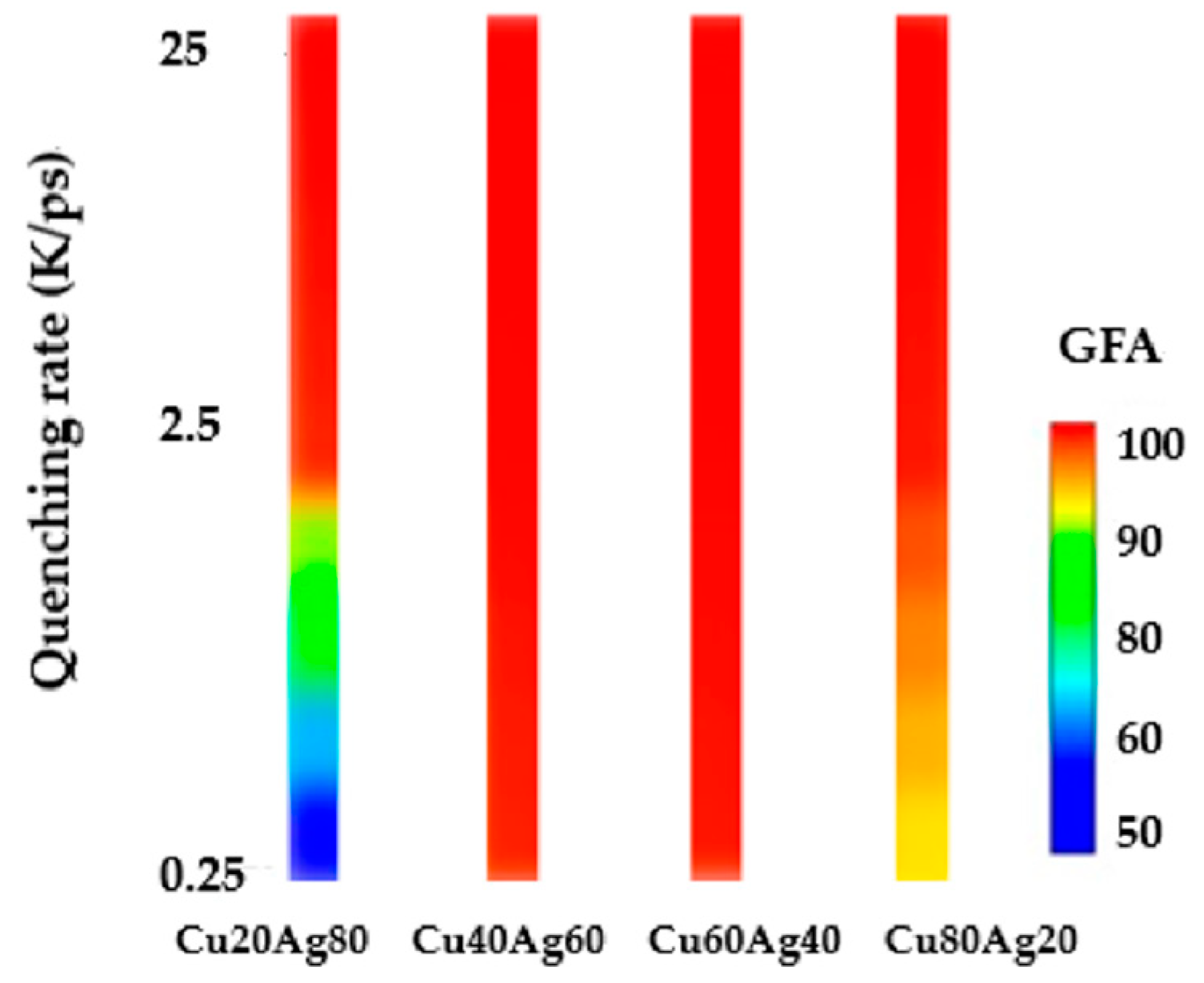
Index of glass-forming ability (GFA) is an indication how easy a liquid metal can be made into amorphous solid by cooling. For example, index GFA 80 at a certain specific quenching rate means 80% amorphous solid can be achieved under this quenching rate. Figure 4 indicates that the glass-forming ability (GFA) of binary Cu–Ag system with different quenching rate as the composition ranges from 20 at.% to 80 at.% Cu. From this figure, the predicted GFA of the Cu–Ag system indicated the glass-formation composition range of the Cu–Ag system as 40 at.%–60 at.% Cu with quenching rate of 0.25 K/ps. However, once the quenching rate reaches 2.5 K/ps, all the compositions that range from 20 at.% to 80 at.% Cu convert to amorphous. In addition, when the ratio of Cu and Ag atoms is nearly 1:1, the alloy shows better GFA. The glass-formation composition range of the Cu–Ag system provides further evidence for the reliability of the present simulations, and they could offer helpful guides to search for alloys with superior physical, chemical, or mechanical properties.
The common neighbor analysis (CNA) of Cu20Ag80 and Cu60Ag40 alloys at two different quenching rates is shown in Figure 5. The gray, green, red, blue, and yellow balls represent amorphous, FCC (body-centered cubic), HCP (hexagonal closest packed), BCC (body-centered cubic), and ICO structures, respectively. It can be seen in Figure 5b that crystalline phases appear significantly in Cu20Ag80 at low quenching rate of 0.25 K/ps, while amorphous is dominating in Cu20Ag80 at high quenching rate of 25 K/ps, as shown in Figure 5a, and in Cu60Ag40 within the quenching rate of 0.25–25 K/ps, as shown in Figure 5c,d. These results are well consistent to the GFA in Figure 4.

3.3. Honeycutt–Anderson (HA) Bond Pair Analysis

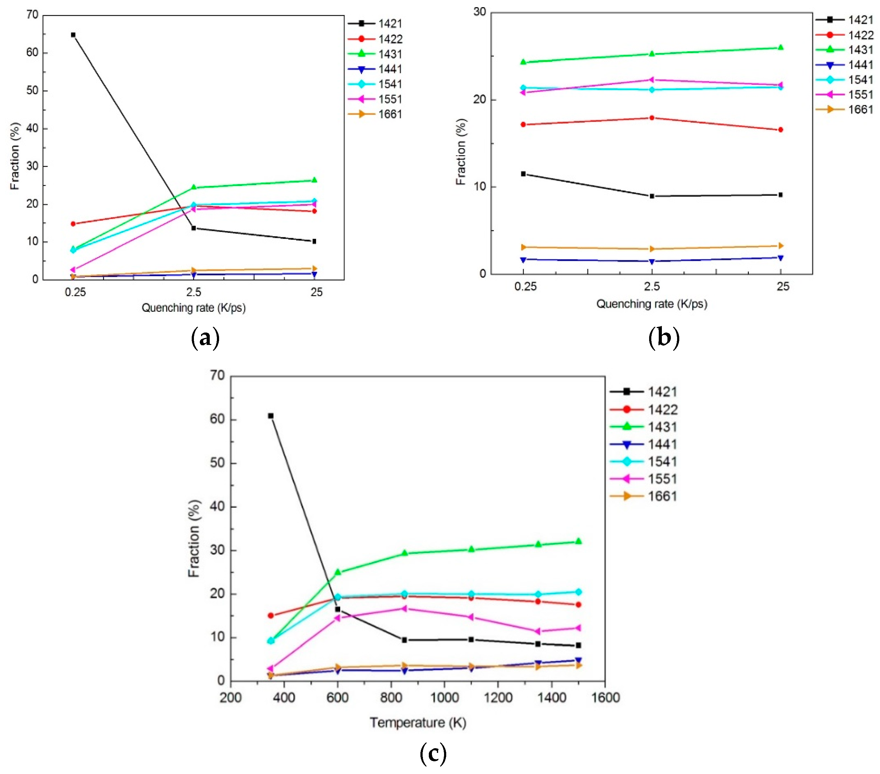
The analysis of the transformation between local structures of Cu–Ag layer at different temperatures was performed by Honeycutt–Anderson (HA) [45]. Based on the definition of the HA bond-type index, different pairs of atoms under consideration in a system can be completely described by four numbers i, j, k, l. If they are bonded in the root pair, the first integer i is 1, otherwise i is 2. The number of near neighbors shared in common was described by the second integer j. The third number k represented the number of bonds among the shared neighbors. However, these three numbers were still insufficient to characterize a diagram uniquely. A fourth integer l, therefore, was required to resolve the ambiguity about the arrangement of the atomic bonds. By using this HA bond-type index, the bond-types between two atoms can be identified clearly. As mentioned in the literature [45], eleven kinds of normalized abundance of pairs in bulk system are involved, i.e., 2211, 2101, 1421, 2441, 1422, 2331, 1551, 1541, 1321, 2321, and 1311. For example, the HA indexes of FCC and HCP crystal structures are 1421 and 1422, respectively. Indexes 1431, 1541, and 1551 represented the icosahedral local structures, which occupied the largest fraction in the amorphous or liquid state. Among these three indexes, the 1551 pair was particularly characteristic of the icosahedral ordering; while the 1541 and 1431 were the indexes for the defect icosahedra and FCC defect local (or distorted icosahedra) structures, respectively. Moreover, indexes 1661 and 1441 were used to identify the local BCC structure. Finally, the indexes 1321 and 1311 denoted the packing related to rhombohedral pairs, or the side product accompanying icosahedral atomic packing. The fractions of seven main bond-types for alloys of Cu20Ag80 and Cu60Ag40 at different quenching rates (0.25, 2.5 and 25 K/ps) were as shown in Figure 6a,b, respectively. It can be found that most of the defect and disorder icosahedral local structures (1541 and 1431 pairs) and the icosahedral short-range order (1551 pair) were created in Cu60Ag40 in comparison with Cu20Ag80. This indicated that Cu60Ag40 has higher proportion of amorphous structure, while a significant ratio of crystalline phase still remains in Cu20Ag80 at low temperature under low quenching rate of 0.25 K/ps. On the other hand, the effects of temperature on the fraction of various bond-types of Cu80Ag20 alloy at quenching rate of 0.25 K/ps were depicted in Figure 6c. It can be seen that the effects of the temperature on the different bond-types were insignificant when the temperature was above 800 K, and their variation trends were almost the same. However, as the temperature decreases continually from 800 to 300 K, the effects of temperature on the fraction of various bond-types became remarkable, especially on the 1421 and 1431 bond-types. At 300 K of final stage, the crystalline structures were formed at low quenching rate of 0.25 K/ps in the systems with 1421 and 1422 bond-types as the dominant types, and the amorphous structures are formed at higher quenching rate in the systems with 1431 and 1541 and 1551 bond-types as the dominant types. The fractions of 1441 and 1661 pairs only changed slightly from 1500 to 800 K and remained almost constant until 350 K. From all these results, similar to those obtained for other cases [46,47,48,49], it can be seen that the effects of different quenching rates on the microstructures of liquid and super-cooled states were insignificant. However, the effects of them on solid (crystal) states were more significant and can only be fully displayed near the liquid–solid transition points [50].

3.4. Diffusion between Cu–Ag and Cu

In order to understand the diffusion behavior between copper and various Cu–Ag alloys, the interface between Cu and Cu–Ag alloys has been investigated at various time steps. Figure 7 shows the cross-section snapshots of Cu20Ag80/Cu interface under two different quenching rates after 2000 ps equilibration process. The crossover profiles in this figure clearly display the inter-diffusion of these atoms occurring near the Cu and Cu–Ag alloy interfaces during the thermal process. When the Cu20Ag80 is produced at quenching rate of 0.25 K/ps, a high ratio of crystalline structure still can be found in the material. This kind of crystalline structure cannot effectively block the diffusion of Cu atoms across the interface between Cu and Cu–Ag layers especially at elevated temperature. Consequently, there exists significant interfacial diffusion between Cu and Cu–Ag as the temperature reaches 700 K. Figure 7a shows that more than 7000 atoms of Cu diffuse from Cu layer into the Cu–Ag layer at 700 K after 2000 ps. These phenomena of diffusion can be seen in Figure 8. The interatomic interaction already leads to some local atomic movement at the interface. Some Cu atoms diffuse into the Cu–Ag layer and blends with it. The region of interface becomes fuzzy. This is two-way diffusion and the domain where such crossover occurs termed as the inter-diffusion zone. However, the situation changes significantly when the quenching rate reaches 25 K/ps. No significant diffusion behavior is observed between the Cu and Cu20Ag80 interface since a significant ratio of amorphous phase is produced at this high quenching rate. As shown in Figure 7b, only a few atoms of Cu deviate from their original lattice positions and diffuse into the Cu–Ag layer. On the other hand, when the Cu40Ag60 alloy is produced with quenching rate between 0.25 and 25 K/ps, no significant diffusion behavior is observed because of the effect of amorphous phase. Between the Cu and Cu40Ag60, only few Cu atoms deviate from their original lattice positions, and the interface still remains clearly. In addition, as the temperature increases, the inter-diffusion layer becomes thicker. This indicates the thickness of the Cu/Cu–Ag interface strongly depends on the thermal process temperature, i.e., the higher the temperature, the thicker the interface.
To further characterize quantitatively the diffusion process, the concentration profile is acquired. Figure 8 shows the concentration distributions of Cu and Cu20Ag80 atoms along the diffusion couple (z-axis) direction obtained at 700 K after 2000 ps with different quenching rates. A region is defined as interfacial region if the concentration of Cu and Cu–Ag are both over 5 at.%. Thus, the thickness of the interfacial region can be estimated from the concentration curves. The profiles of concentration curves in Figure 8a show the case of Cu20Ag80 with the slowest quenching rate of 0.25 K/ps. The thickness of the interfacial region grows and reaches 7~8 nm at 2000 ps, which can be seen from the coordinates of the diffusion zone boundaries or fronts. As shown in Figure 8b, the thickness of the interfacial region becomes approximately 1~2 nm only when the quenching rate increases to 25 K/ps. This indicates that there is no obvious diffusion between Cu and Ag atoms. In addition, Figure 8a also shows that the interfacial region consists of rich-Cu and rich-Cu–Ag phases, and the thickness of rich-Cu–Ag phase is larger than that of the rich-Cu phase. This indicates that the main diffusion is from Cu to Cu–Ag. This phenomenon is similar as pure copper diffuses to pure silver [51]. The mean-square displacement (MSD) profiles at temperatures ranging from 300 to 900 K for Cu–Ag amorphous metal were used to investigate their dynamical properties. The MSD is defined by a function of time as shown in Equation (1):
MSD = i N [ r i ( t ) r i ( t 0 ) ] 2 N
where ri(t) represents the position of atom i at delay time t, and ri(t0) indicates the reference position of the corresponding atom at reference time t0; N represents the total atom number of the investigated system. Generally, the MSD profile is linear to the delay time over the long-time limit, the slopes of the MSD profile are generally larger with the increasing temperature. The diffusion coefficients of Cu and Cu–Ag alloys at the interface can be derived from the slopes of MSD profiles with a longer delay time by the Einstein equation: [52,53]
D = 1 6 N lim n d d t MSD
where D is the diffusion coefficient, and N is the number of atoms.
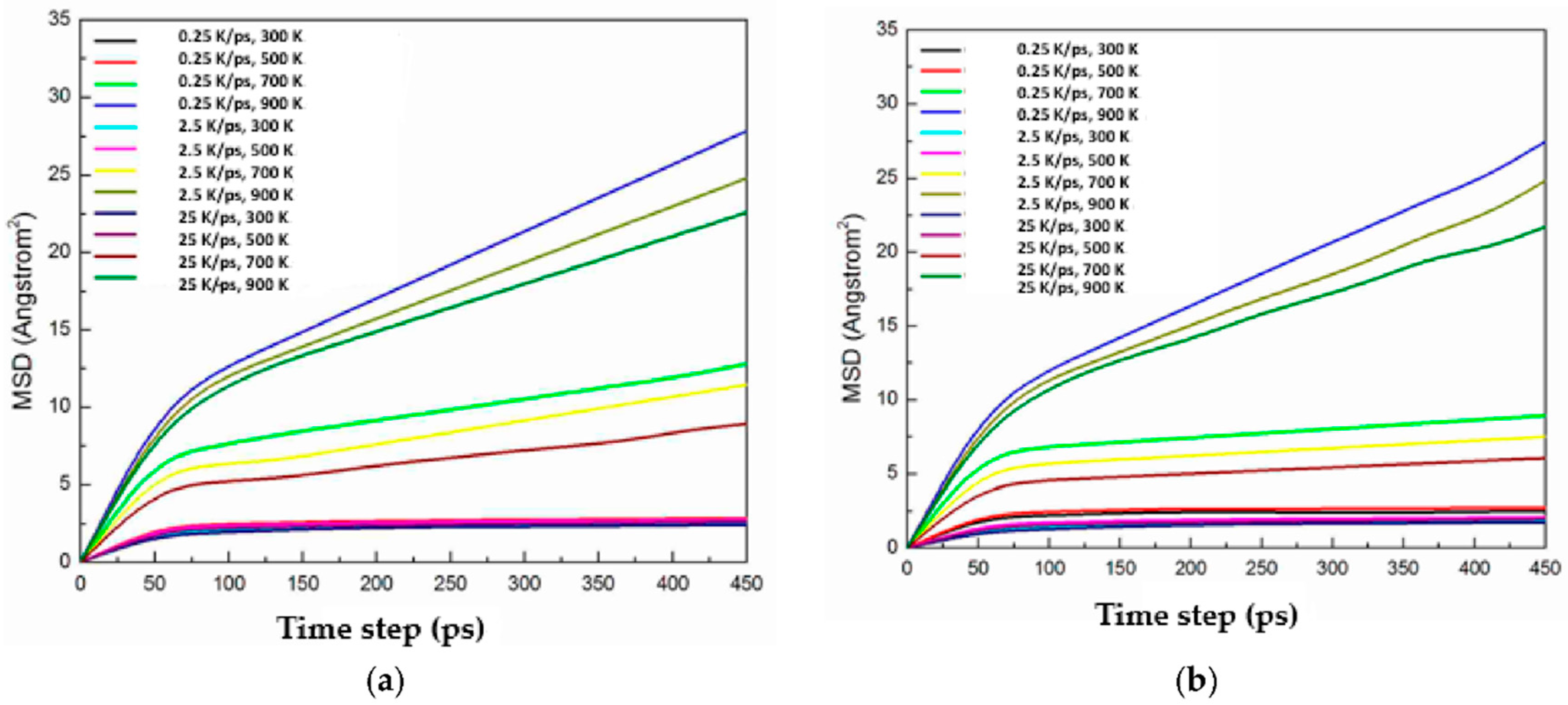
Figure 9 shows the MSD of Cu and Cu–Ag as a function of time at various temperatures. From this figure, it can be clearly observed that the slopes of MSD profile are generally larger at a higher temperature and the MSD values of Cu–Ag alloy made from slower quenching rate are larger, indicating the mobility of atoms in Cu–Ag alloy made from slower quenching rate is higher than those made from higher quenching rate. On the other hand, the MSD values of Cu20Ag80 and Cu80Ag20 are generally larger than Cu40Ag60 and Cu60Ag40, indicating the mobility of atoms in more crystalline structure is higher than those with more amorphous structures. For time below 0.1 ps, the MSD is proportional to the square of time, t2, as expected for ballistic motion [54]. For longer times the MSD increases linearly with time, indicating the phenomenon of long-range diffusion [55]. The MSD is linear to the delay time in the long-time limit, so the self-diffusion coefficients of Cu and Cu–Ag alloys can be derived from the slopes of MSD profiles by the Einstein equation.
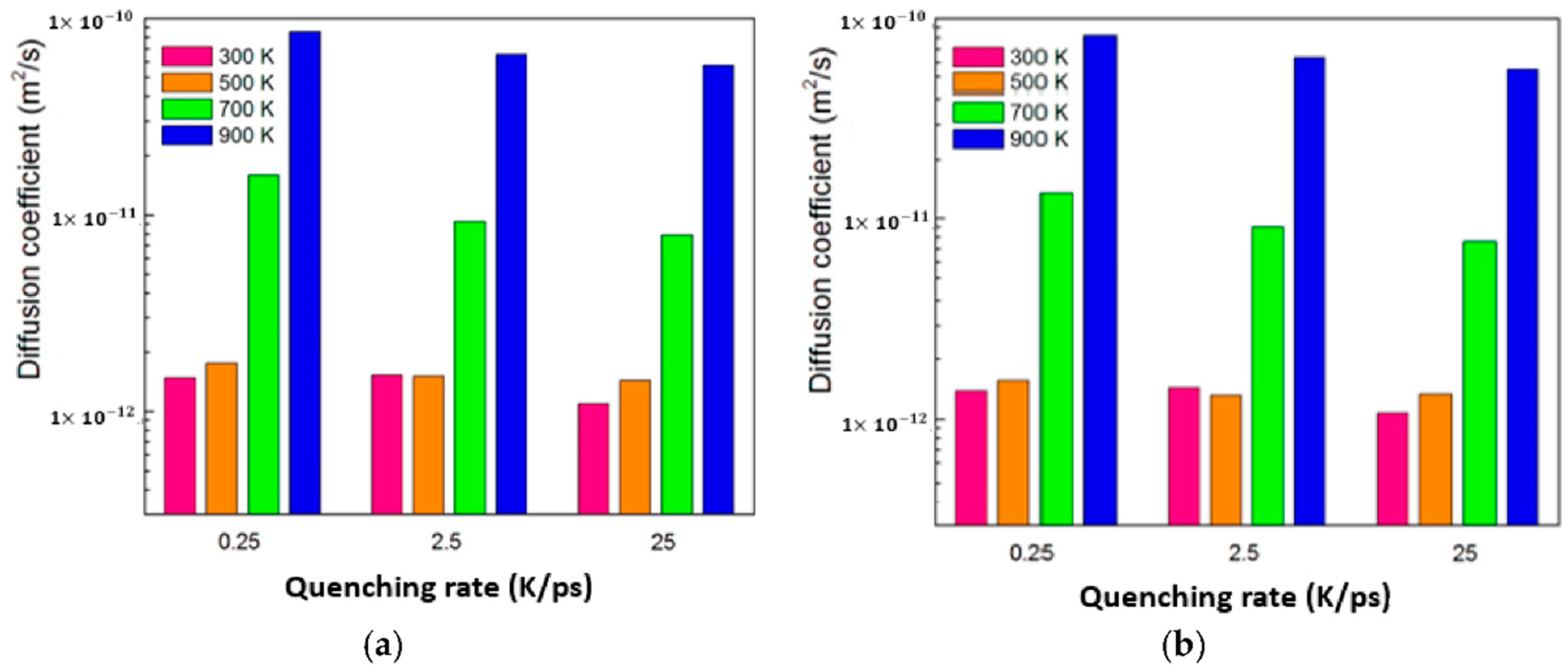
The total diffusion coefficients near the Cu/Cu–Ag interface at different temperatures are shown in Figure 10. It can be inferred that the diffusion coefficients of both Cu and Cu–Ag significantly increase with the increasing temperature when the system temperature exceeds the glass transition temperature. The values of these diffusion coefficients range between 1 × 10⁻¹² and 1 × 10⁻¹⁰ m2/s, which has the same order than those found in the experimental measurement for the bulk inter-diffusion region. It is worth noting that the MSD calculated by the MD may be slightly lower than the experimental value. This is due to the MD is relatively unable to consider the satiation of bulk materials, such as defects and so on. Perfect structure in MD leads to the considerable cage effect, which causes the backflow of atoms when an atom interacts with atoms of local structure, resulting in jumping back to its initial position and lowering diffusivity. For reasons outlined above, introduction of amorphous diffusion barrier is then considered to be the best mitigation strategy to prevent the interdiffusion between Cu and Sn. Therefore, TFMGs of Cu–Ag alloys are considered to be the promising diffusion barrier.

3.5. Tensile Behavior

In order to understand the mechanical behavior of amorphous and crystalline states, the deformation and fracture mechanism of a bilayer structural specimen (Cu/Cu20Ag80) with different amorphous ratios made by different quenching rate under tensile stress were compared as shown in Figure 11. Figure 11a represents the stress–strain response of the Cu/Cu20Ag80 produced at both higher 25 K/ps and lower 0.25 K/ps quenching rates under mode-I loading at a temperature of 100 K and strain rate of 1 × 10⁹ s−1. For Cu20Ag80 produced at slower quenching rate (0.25 K/ps), in which crystalline and amorphous phases coexist, the stress reaches a higher maximum and then suddenly drops. This is followed by a more steady flow regime during which some serrations are evident. The sudden drops are caused by the formation of voids near the Cu/Cu20Ag80 interface. However, for samples produced with higher quenching rate (25 K/ps), in which amorphous is major phase, the stress–strain curves are smoother and the behavior is close to the ideal elastic-perfectly-plastic response. This phenomenon is quite different from the single crystal metallic of dislocations undergoing slippage along the slip plane [39,45]. The void nucleation is attributed to the fact that there exist more defects in this local region, and they are generally formed by the coalescences of the free volume present in the metallic glass system [56], which becomes the weakness during the tensile deformation. Figure 11b,c depict the atomic position snapshots of the interface model captured at different strains till fracture under quenching rates of 25 and 0.25 K/ps, respectively. In comparison with these two figures, it reveals that for the specimen produced at faster quenching rate (25 K/ps), the initial position of the void tends to move from the Cu/Cu20Ag80 interface to the middle of the Cu–Ag, which indicates that the Cu/Cu20Ag80 interface is stronger than Cu20Ag80 alloy. In addition, it was observed that larger voids are created in the samples of Cu20Ag80 with quenching rate of 25 K/ps than with 0.25 K/ps at about 13% strain. We also found that when the Ag content of the specimens ranges between 40 at.% and 60 at.%, voids tend to occur at higher strain values (15% strain), or the plasticity behavior is more significant. From the microstructure side, by quenching the model at different quenching rates, different degree of structural ordering of the ordered clusters can be produced. The fraction of icosahedra in the as-quenched Cu–Ag MG sample increases considerably with decreasing quenching rate. The increasing number of icosahedral clusters forms a more extended and stronger elastic backbone, leading to higher stiffness (Young’s modulus) and yield strength. The above observations are in good agreement with our prior simulations and the results conducted in the literature [57,58,59].

4. Conclusions

The local atomic pairing arrangement of Cu–Ag system with different quenching rates was simulated by MD simulation method. The following conclusions can be reached from this study:
  • Cu20Ag80 is 50% amorphous at quenching rate of 0.25 K/ps, whereas Cu40Ag60, Cu60Ag40, and Cu80Ag20 are more than 95% amorphous at quenching rate between 0.25 K/ps and 25 K/ps. In other words, Cu–Ag alloys exhibit excellent GFA except Cu20Ag80.
  • A diffusion region of 1 to 2 nm at 700 K occurs between copper and Cu40Ag60, or Cu60Ag40, or Cu80Ag20 as quenched within the range from 0.25 to 25 K/ps. However, a diffusion region of approximately 7 to 8 nm takes place at 700 K between copper and Cu20Ag80 quenched by 0.25 K/ps. In other words, the layer with higher ratio of amorphous exhibits a better performance of diffusion barrier.
  • Simulation results of tensile test show that the stress–strain curves of Cu–Ag alloys having higher ratio of amorphous (for instance, Cu20Ag80 produced at higher quenching rate 25 K/ps, and other ratios of Cu–Ag alloys at quenching rate 0.25–25 K/ps) are smoother and the behavior is close to the ideal elastic-perfectly-plastic response. The void initiates in the Cu–Ag layer first and then gradually enlarges. This phenomenon indicates that the Cu/Cu–Ag interface is stronger than Cu–Ag alloy. For the Cu20Ag80 alloy produced at slower quenching rate (0.25 K/ps), in which both crystalline and amorphous phases exist together, as the strain increases, its stress gradually reaches a higher maximum and then suddenly drops. This is followed by a steady flow regime during which some serrations are evident. The sudden drops are caused by the formation of voids near the Cu/Cu20Ag80 interface. This phenomenon of sudden drop in stress is different from the crystal metallic of dislocations undergoing slippage along the slip plane.

Author Contributions

For P.-H.S. and T.-C.C. conceived and proposed the conceptualization and methodology; P.-H.S. applied the software, performed the simulations and experiments, and drew the figures; P.-H.S. and T.-C.C. performed the validation, formal analysis, data, as well as writing in the stages of original draft preparation, review and editing, and visualization; T.-C.C. conducted the supervision, project administration, and funding acquisition. All authors have read and agreed to the published version of the manuscript.

Funding

This research was funded by the Ministry of Science and Technology of Taiwan, Grant number MOST Nos. 107-2221-E-006-122- and 108-2221-E-006-191-.

Conflicts of Interest

The authors declare no conflict of interest.

References

  1. Lim, S.P.S.; Ding, M.Z.; Kawano, M. Chip-to-Wafer (C2W) flip chip bonding for 2.5D high density interconnection on TSV free interposer. In Proceedings of the 19th Electronics Packaging Technology Conference IEEE (EPTC), Singapore, 6–9 December 2017; pp. 1–7. [Google Scholar]
  2. Murarka, S.P. Multilevel interconnections for ULSI and GSI era. Mater. Sci. Eng. R 1997, 19, 87–151. [Google Scholar] [CrossRef]
  3. Sorensen, M.R.; Mishin, Y.; Voter, A.F. Diffusion mechanisms in Cu grain boundaries. Phys. Rev. B 2000, 62, 3658–3673. [Google Scholar] [CrossRef] [Green Version]
  4. Ojovan, M.I.; Lee, W.B.E. Connectivity and glass transition in disordered oxide systems. J. Non-Crystal. Solids 2010, 356, 2534–2540. [Google Scholar] [CrossRef]
  5. Diyatmika, W.; Chu, J.P.; Yen, Y.; Hsueh, C. Sn whisker mitigation by a thin metallic-glass underlayer in Cu-Sn. Appl. Phys. Lett. 2013, 103, 241912. [Google Scholar] [CrossRef]
  6. Wu, Y.; Sees, J.A.; Pouraghabagher, C.; Foster, L.A.; Marshall, J.L.; Jacobs, E.G.; Pinizzotto, R.F. The formation and growth of intermetallics in composite solder. J. Electron. Mater. 1993, 22, 769–777. [Google Scholar] [CrossRef]
  7. Diyatmika, W.; Chu, J.P.; Yen, Y.; Chang, W.; Hsueh, C. Thin film metallic glass as an underlayer for tin whisker mitigation: A room-temperature evaluation. Thin Solid Films 2014, 561, 93–97. [Google Scholar] [CrossRef]
  8. Muehlbacher, M.; Bochkarev, A.S.; Mendez-Martin, F.; Sartory, B.; Chitu, L.; Popov, M.N.; Puschnig, P.; Spitaler, J.; Ding, H.; Schalk, N.; et al. Cu diffusion in single-crystal and polycrystalline TiN barrier layers: A high-resolution experimental study supported by first-principles calculations. J. Appl. Phys. 2015, 118, 085307. [Google Scholar] [CrossRef]
  9. Popov, M.N.; Bochkarev, A.S.; Razumovskiy, V.I.; Puschnig, P.; Spitaler, J. Point defects at the Σ5 (012)[100] grain boundary in TiN and the early stages of Cu diffusion: An ab initio study. Acta Mater. 2018, 144, 496–504. [Google Scholar] [CrossRef]
  10. Sangiovanni, D.G. Copper adatom, admolecule transport, and island nucleation on TiN (001) via ab initio molecular dynamics. Appl. Surf. Sci. 2018, 450, 180–189. [Google Scholar] [CrossRef]
  11. Wu, W.F.; Tsai, K.C.; Chao, C.G.; Chen, J.C.; Ou, K.L. Novel multilayered Ti/TiN diffusion barrier for Al metallization. J. Electron. Mater. 2005, 34, 1150–1156. [Google Scholar] [CrossRef]
  12. Lee, C.H.; Wong, Y.M.; Doherty, C.; Tai, K.L.; Lane, E.; Bacon, D.D.; Baiocchi, F.; Katz, A. Study of Ni as a barrier metal in AuSn soldering application for laser chip/submount assembly. J. Appl. Phys. 1992, 72, 3808–3815. [Google Scholar] [CrossRef]
  13. Chang, C.A. Interactions between Au and Cu across a Ni barrier layer. J. Appl. Phys. 1986, 50, 1220–1222. [Google Scholar] [CrossRef]
  14. Keller, H.N. Solder connections with a Ni barrier. IEEE Trans. Comp. Hybrids Manufac. Technol. 1986, 9, 433–439. [Google Scholar] [CrossRef]
  15. Iwamoto, N.; Truong, N.; Lee, E. New metal layers for integrated circuit manufacture: Experimental and modeling studies. Thin Solid Films 2004, 469, 431–437. [Google Scholar] [CrossRef]
  16. Sung, P.H.; Chen, T.C. Material properties of Zr–Cu–Ni–Al thin films as diffusion barrier layer. Crystals 2020, 10, 540. [Google Scholar] [CrossRef]
  17. Jen, M.H.R.L.; Liu, C.; Lai, Y.S. Electromigration test on void formation and failure mechanism of FCBGA lead-free solder joints. IEEE Trans. Comp. Pack. Technol. 2009, 32, 79–88. [Google Scholar] [CrossRef]
  18. Rymaszewski, E.; Walsh, J.; Leehan, G. Semiconductor logic technology in IBM. IBM J. Res. Dev. 1981, 25, 603–616. [Google Scholar] [CrossRef]
  19. Zhang, Z.; Wong, C. Recent advances in flip-chip underfill: Materials, process, and reliability. IEEE Trans. Adv. Pack. 2004, 27, 515–524. [Google Scholar] [CrossRef]
  20. An, B.; Kwon, Y.; Oh, J.; Yang, C. Amorphous TaxMnyOz layer as a diffusion barrier for advanced copper interconnects. Sci. Rep. 2019, 9, 20132. [Google Scholar] [CrossRef]
  21. An, B.; Kwon, Y.; Oh, J.; Lee, C.; Choi, S.; Kim, H.; Lee, M.; Pae, S.; Yang, C. Characteristics of an amorphous carbon layer as a diffusion barrier. ACS Appl. Mater. Inter. 2020, 12, 3104–3113. [Google Scholar] [CrossRef]
  22. Hüger, E.; Strauß, F.; Stahn, J.; Deubener, J.; Bruns, M.; Schmidt, H. In-situ measurement of self-atom diffusion in solids using amorphous germanium as a model system. Sci. Rep. 2018, 8, 17607. [Google Scholar] [CrossRef]
  23. Ou, K.L.; Wu, W.F.; Chou, C.P.; Chiou, S.Y.; Wu, C.C. Improved TaN barrier layer against Cu diffusion by formation of an amorphous layer using plasma treatment. J. Vac. Sci. Technol. B 2002, 20, 2154–2161. [Google Scholar] [CrossRef]
  24. Wang, C.; Yiu, W.P.; Chu, J.P.; Shek, C.H.; Hsueh, C.H. Zr–Ti–Ni thin film metallic glass as a diffusion barrier between copper and silicon. J. Mater. Sci. 2015, 50, 2085–2092. [Google Scholar] [CrossRef]
  25. Ribbe, J.; Schmitz, G.; Divinski, S.V. Grain boundary diffusion of Fe in high-purity copper. Defect Diffus. Forum 2009, 289–292, 211–217. [Google Scholar] [CrossRef]
  26. Si, C.; Duana, B.; Zhang, Q.; Cai, J.; Wu, W. Microstructure, corrosion-resistance, and wear-resistance properties of subsonic flame sprayed amorphous Fe–Mo–Cr–Co coating with extremely high amorphous rate. J. Mater. Res. Technol. 2020, 9, 3292–3303. [Google Scholar] [CrossRef]
  27. Ning, W.; Zhai, H.; Xiao, R.; He, D.; Li, W.; Li, X. The corrosion resistance mechanism of Fe-based amorphous coatings synthesised by detonation gun spraying. J. Mater. Eng. Perform. 2020, 29, 3921–3929. [Google Scholar] [CrossRef]
  28. Tran, A.S.; Fang, T.H. Void growth and coalescence in Cu–Ta metallic glasses using molecular dynamics. Comput. Mater. Sci. 2019, 168, 144–153. [Google Scholar] [CrossRef]
  29. Tran, A.S.; Fang, T.H. Size effect and interfacial strength in nanolaminated Cu/CuxTa100-x composites using molecular dynamics. Comput. Mater. Sci. 2020, 184, 109890. [Google Scholar] [CrossRef]
  30. Hsieh, J.; Hung, S. The effect of Cu:Ag atomic ratio on the properties of sputtered Cu–Ag alloy thin films. Materials 2016, 9, 914. [Google Scholar] [CrossRef] [Green Version]
  31. Wang, K.; Fujita, T.; Chen, M.W.; Nieh, T.G.; Okada, H.; Koyama, K.; Zhang, W.; Inoue, A. Electrical conductivity of a bulk metallic glass composite. Appl. Phys. Lett. 2007, 91, 154101. [Google Scholar] [CrossRef]
  32. Szymanska, I.B.; Piszczek, P.; Bala, W.; Bartkiewicz, K.; Szlyk, E. Ag/Cu layers grown on Si(111) substrates by thermal inducted chemical vapor deposition. Surf. Coat. Technol. 2007, 201, 9015–9020. [Google Scholar] [CrossRef]
  33. Wei, M.Z.; Xu, L.J.; Shi, J.; Pan, G.J.; Gao, Z.H.; Meng, M.K. Achieving high strength and high electrical conductivity in Ag/Cu multilayers. Appl. Phys. Lett. 2015, 106, 011604. [Google Scholar] [CrossRef]
  34. Strehle, S.; Menzel, S.; Wetzig, K.; Bartha, J.W. Microstructure of electroplated Cu(Ag) alloy thin films. Thin Sol. Films 2011, 519, 3522–3529. [Google Scholar] [CrossRef]
  35. Spolenak, R.; Kraft, O.; Arzt, E. Effects of alloying elements on electromigration. Microelectron. Reliab. 1998, 38, 1015–1020. [Google Scholar] [CrossRef]
  36. Plimpton, S. Fast parallel algorithms for short-range molecular-dynamics. J. Comput. Phys. 1995, 117, 1–19. [Google Scholar] [CrossRef] [Green Version]
  37. Stukowski, A. Visualization and analysis of atomistic simulation data with OVITO-the Open Visualization Tool. Model. Simul. Mater. Sci. Eng. 2010, 18, 015012. [Google Scholar] [CrossRef]
  38. Rassoulinejad-Mousavi, S.M.; Mao, Y.; Zhang, Y. Evaluation of copper, aluminum, and nickel interatomic potentials on predicting the elastic properties. J. Appl. Phys. 2016, 119, 244304. [Google Scholar] [CrossRef]
  39. Daw, M.S.; Baskes, M.I. Embedded-atom method: Derivation and application to impurities, surfaces, and other defects in metals. Phys. Rev. B 1984, 29, 6443–6453. [Google Scholar] [CrossRef] [Green Version]
  40. Gupta, P.; Pal, S.; Yedla, N. Molecular dynamics based cohesive zone modeling of Al (metal)–Cu50Zr50 (metallic glass) interfacial mechanical behavior and investigation of dissipative mechanisms. Mater. Des. 2016, 105, 41–50. [Google Scholar] [CrossRef]
  41. Gear, C.W. Numerical Initial Value Problems in Ordinary Differential Equations; Prentice-Hall: Englewood Cliffs, NJ, USA, 1971. [Google Scholar]
  42. Mohazzabi, P. Temperature dependence of the elastic constants of copper, gold and silver. J. Phys. Chem. Solids 1985, 46, 147–150. [Google Scholar] [CrossRef]
  43. Qi, L.; Zhang, H.; Hu, Z. Molecular dynamic simulation of glass formation in binary liquid metal: Cu–Ag using EAM. Intermetallics 2004, 12, 1191–1195. [Google Scholar] [CrossRef]
  44. Qi, Y.; Çağın, T.; Kimura, Y.; Goddard, W.A., III. Molecular-dynamics simulations of glass formation and crystallization in binary liquid metals: Cu–Ag and Cu–Ni. Phys. Rev. B 1999, 59, 3527–3533. [Google Scholar] [CrossRef] [Green Version]
  45. Honeycutt, J.; Andersen, H.C. Molecular-dynamics study of melting and freezing of small Lennard-Jones clusters. J. Phys. Chem. 1987, 91, 4950–4963. [Google Scholar] [CrossRef]
  46. Rangsu, L.; Jiyong, L.; Kejun, D.; Caixing, Z.; Hairong, L. Formation and evolution properties of clusters in a large liquid metal system during rapid cooling processes. Mater. Sci. Eng. B 2002, 94, 141–148. [Google Scholar] [CrossRef]
  47. Dong, K.; Liu, R.; Yu, A.; Zou, R.; Li, J. Simulation study of the evolution mechanisms of clusters in a large-scale liquid Al system during rapid cooling processes. J. Phys. 2003, 15, 743–753. [Google Scholar] [CrossRef]
  48. Liu, R.S.; Dong, K.J.; Li, J.Y.; Yu, A.B.; Zou, R.P. Formation and description of nano-clusters formed during rapid solidification processes in liquid metals. J. Non-Crystal. Solids 2005, 351, 612–617. [Google Scholar] [CrossRef]
  49. Liu, R.S.; Dong, K.J.; Tian, Z.A.; Liu, H.R.; Peng, P.; Yu, A.B. Formation and magic number characteristics of clusters formed during solidification processes. J. Phys. 2007, 19, 196103. [Google Scholar] [CrossRef]
  50. Liu, H.R.; Liu, R.S.; Zhang, A.L.; Hou, Z.Y.; Wang, X.; Tian, Z.A. A simulation study of microstructure evolution during solidification process of liquid metal Ni. Chin. Phys. 2007, 16, 3747–3753. [Google Scholar]
  51. Chen, S.; Soh, A.; Ke, F. Molecular dynamics modeling of diffusion bonding. Scrip. Mater. 2005, 52, 1135–1140. [Google Scholar] [CrossRef] [Green Version]
  52. Meunier, M. Diffusion coefficients of small gas molecules in amorphous cis-1, 4-polybutadiene estimated by molecular dynamics simulations. J. Chem. Phys. 2005, 123, 134906. [Google Scholar] [CrossRef]
  53. Ju, S.P.; Wu, T.Y.; Liu, S.H. Mechanical and dynamical behaviors of ZrSi and ZrSi2 bulk metallic glasses: A molecular dynamics study. J. Appl. Phys. 2015, 117, 105103. [Google Scholar] [CrossRef]
  54. Faupel, F.; Frank, W.; Macht, M.P.; Mehrer, H.; Naundorf, V.; Rätzke, K.; Schober, H.R.; Sharma, S.K.; Teichler, H. Diffusion in metallic glasses and supercooled melts. Rev. Mod. Phys. 2003, 75, 237–280. [Google Scholar] [CrossRef] [Green Version]
  55. Todorov, T.; Sutton, A. Force and conductance jumps in atomic-scale metallic contacts. Phys. Rev. B 1996, 54, R14234. [Google Scholar] [CrossRef] [PubMed]
  56. Yamakov, V.; Wolf, D.; Phillpot, S.R.; Mukherjee, A.K.; Gleiter, H. Dislocation processes in the deformation of nanocrystalline aluminium by molecular-dynamics simulation. Nat. Mater. 2002, 1, 45–48. [Google Scholar] [CrossRef] [PubMed]
  57. Cheng, Y.; Ma, E. Atomic-level structure and structure–property relationship in metallic glasses. Prog. Mater. Sci. 2011, 56, 379–473. [Google Scholar] [CrossRef]
  58. Shi, Y.; Falk, M.L. Strain localization and percolation of stable structure in amorphous solids. Phys. Rev. Lett. 2005, 95, 095502. [Google Scholar] [CrossRef] [Green Version]
  59. Albano, F.; Lacevic, N.; Falk, M.L.; Glotzer, S.C. Relating metallic glass mechanical properties to liquid structure. Mater. Sci. Eng. A 2004, 375, 671–674. [Google Scholar] [CrossRef]
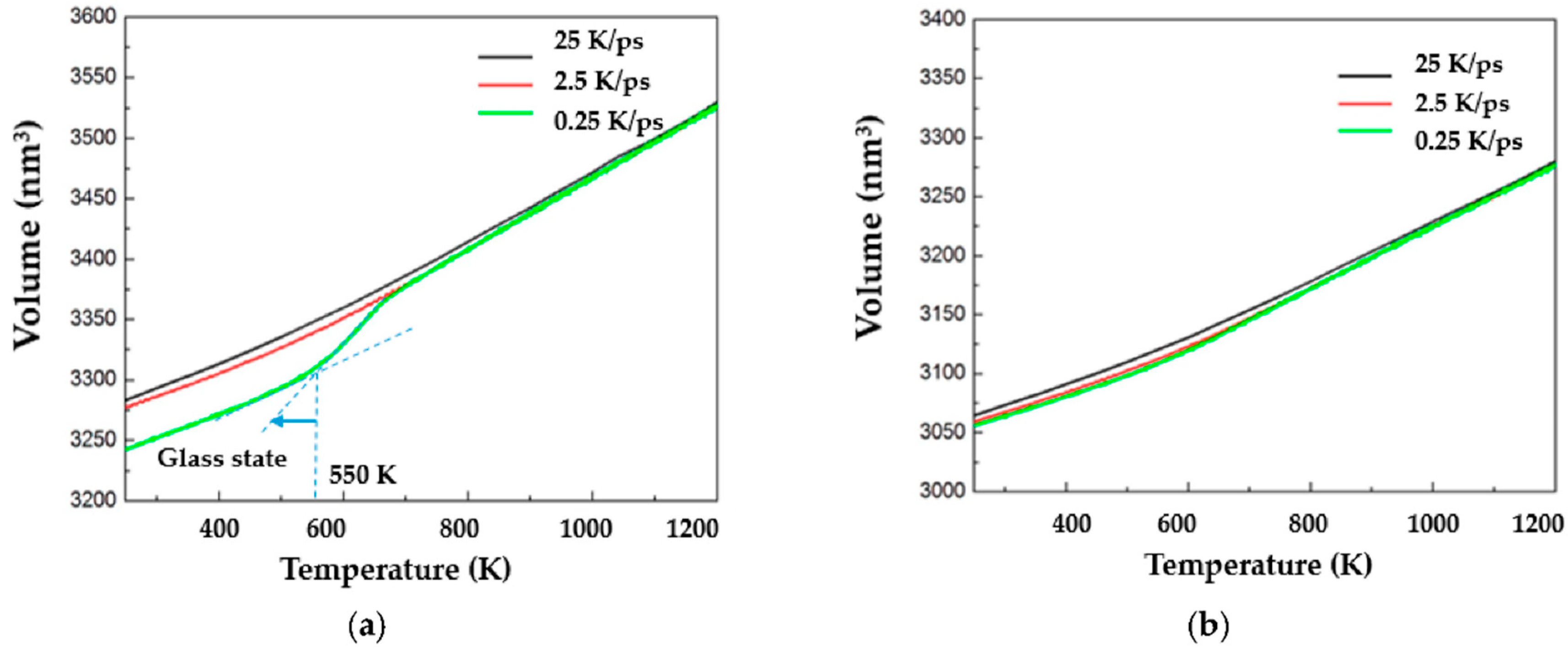
Figure 1. Volumes vary as a function of temperature at different quenching rates for (a) Cu20Ag80 and (b) Cu40Ag60 alloys (glass transition temperature (Tg) of 550 K, can be approximately determined by extrapolation of two straight dotted lines below and above the transition until they intersect; and the alloys will transform to the glass state as the temperature is lower than Tg).
Coatings 10 01087 g001
Figure 2. Radial distribution functions (RDFs) of Cu–Ag pairs with (a) different quenching rates of Cu40Ag60 and (b) different atomic ratio at quenching rates of 25 K/ps.
Coatings 10 01087 g002
Figure 3. RDFs of Cu40Ag60 at various temperatures with quenching rates of 25 K/ps for (a) Cu–Cu pairs (b) Ag–Ag pairs and (c) Cu–Ag pairs.
Coatings 10 01087 g003
Figure 4. Relationship between glass forming ability, quenching rate, and composition of elements.
Coatings 10 01087 g004
Figure 5. Distribution of common neighbor analysis (CNA) of Cu20Ag80 alloy with quenching rate of (a) 25 K/ps, and (b) 0.25 K/ps; Cu60Ag40 alloy with quenching rate of (c) 25 K/ps, and (d) 0.25 K/ps.
Coatings 10 01087 g005
Figure 6. Honeycutt–Anderson (HA) indices vary as a function of quenching rates at 300 K for (a) Cu20Ag80, (b) Cu60Ag40, (c) HA indices vary as a function of temperature for Cu20Ag80 at quenching rate of 0.25 K/ps.
Coatings 10 01087 g006
Figure 7. The cross-section of Cu20Ag80/Cu interface under quenching rate of (a) 0.25 K/ps, and (b) 25 K/ps (700 K after 2000 ps equilibration process).
Coatings 10 01087 g007
Figure 8. Concentration distributions of Cu20Ag80/Cu quenched at (a) 0.25 K/ps, and (b) 25 K/ps along the diffusion couple (z-axis) direction (700 K after 2000 ps equilibration process).
Coatings 10 01087 g008
Figure 9. The mean-square displacement (MSD) of Cu and (a) Cu20Ag80, and (b) Cu60Ag40 as a function of time under various temperatures at different quenching rates.
Coatings 10 01087 g009
Figure 10. Diffusion coefficient between Cu and layers of (a) Cu20Ag80, (b) Cu60Ag40 under various temperatures at different quenching rates.
Coatings 10 01087 g010
Figure 11. (a) Stress–strain plot of the Cu/Cu20Ag80 interface model under mode-I loading; atomic position snapshots (I), can snapshots (II), and atomic strain snapshots (III) of the interface captured with C20Ag80 under quenching of (b) 0.25 K/ps and (c) 25 K/ps at different strains (300 K).
Coatings 10 01087 g011
Table 1. Elastic constants of Cu and Ag via experimental and molecular dynamics (MD) simulation.
ElementsMethodsC11 (GPa)C12 (GPa)C44 (GPa)
CuExperimental data [38]168.4121.475.4
Calculated data by MD168.5120.875.2
Error (%)0.060.490.27
AgExperimental data [42]124.895.246.0
Calculated data by MD126.194.246.9
Error (%)1.041.051.96
C11, C12, C44: elastic constants in anisotropic elasticity.
Publisher’s Note: MDPI stays neutral with regard to jurisdictional claims in published maps and institutional affiliations.