Article

Fluid Morphologies Governed by the Competition of Viscous Dissipation and Phase Separation in a Radial Hele-Shaw Flow

1
Department of Chemical Engineering, Tokyo University of Agriculture and Technology, Nakacho 2-24-16, Koganei, Tokyo 184-8588, Japan
2
Department of Mathematics, Indian Institute of Technology Roper, Rupnagar 140001, India
3
Division of Chemical Engineering, Department of Materials Engineering Science, Graduate School of Engineering Science, Osaka University, Machikaneyamacho 1-3, Toyonaka, Osaka 560-8531, Japan
*
Author to whom correspondence should be addressed.
Coatings 2020, 10(10), 960; https://doi.org/10.3390/coatings10100960
Submission received: 16 September 2020 / Revised: 30 September 2020 / Accepted: 1 October 2020 / Published: 6 October 2020
(This article belongs to the Special Issue Fluid Interfaces)

Abstract

:
The displacement of a less viscous fluid by a more viscous fluid in a radial Hele-Shaw cell makes a circular pattern because the interface is hydrodynamically stable in this condition. Very recently, it has been experimentally reported that the hydrodynamically stable displacement in a partially miscible system induces fingering patterns while stable circular patterns are made at fully miscible and immiscible systems. The fingering instability in the partially miscible system results from complex and entangled elements involving viscous dissipation, molecular diffusion, and phase separation. The analyzing mechanism requires a quantitative relationship between the hydrodynamic interfacial fingering patterns and underlying physicochemical properties. Here, we experimentally investigated the change in fluid patterns formed by the progression of phase separation in the partially miscible systems and categorized them into three patterns: finger-like pattern, annular-like pattern, and circular pattern. Moreover, we propose the mechanism of the pattern formation by an interfacial tension measurement and evaluate the patterns by modified capillary number and newly defined body force ratio, B f . Our analysis revealed that the deformation index of the pattern can be expressed as a function of B f on a single curve regardless of the miscibility.

1. Introduction

The displacement of one fluid by another in porous media is ubiquitous in several processes such as chromatographic separation [1], transportation of digestive juice [2], CO2 sequestration [3], frontal polymerization [4], and secondary and tertiary oil recovery [5]. It is generally accepted that when the displacing fluid is more viscous, no interfacial instability occurs, while a finger-like pattern forms at the interface in the reverse situation (Figure 1). The latter case, where a less viscous fluid displaces a more viscous one in porous media, is called Saffman–Taylor instability [6] or viscous fingering (VF) [7]. Saffman–Taylor instability, based on Darcy’s law [8,9], can be explained by Figure 2 and Equation (1):
u A u B = u B μ 1 μ 2 μ 2 + μ 1 μ 2 z L δ z L ,
where u is flow velocity, μ is viscosity, δ z is an initial disturbance, L is a length scale of porous media, and indexes A and B represent location. u A and u B represent the velocity at the different locations in the interface between fluid 1 and fluid 2 (Figure 2a). We assume that a velocity fluctuation occurs at the interface, and the velocity at location B becomes faster than the remaining interface at the initial state. Therefore, the interface at location B protrudes from the initial flat interface by the displacement δ z . We have two different combinations of viscosity of the fluids. When displacing fluid 1 is more viscous than the other ( μ 1 > μ 2 ), the right-hand side of Equation (1) becomes positive, and then u A > u B according to Equation (1). In this case, the initial disturbance δ z becomes small. As a result, the disturbance is suppressed, and hydrodynamically stable displacement proceeds. However, when the displacing fluid is less viscous than the other ( μ 1 < μ 2 ), the right-hand side of Equation (1) becomes negative, and then u A < u B , and thus the initial disturbance δ z is enhanced. Therefore, the interface at location B protrudes further, and a finger-like pattern (VF) appears.
The displacement fluid pair can be categorized into three types: fully miscible, partially miscible, and immiscible. The fully miscible system has infinite mutual solubility, like glycerol–water, the partially miscible system has finite mutual solubility, and the immiscible system has zero mutual solubility, like oil–water. The hydrodynamically stable displacement in fully miscible and immiscible systems makes the pattern circular for a radial geometry or flat for a rectangular geometry. Any fluctuation in the interface should always decay as fluid displacement proceeds. However, the hydrodynamically stable displacement in the partially miscible system shows not a circular but a finger-like pattern [10]. There are many studies on the displacement in the porous media or Hele-Shaw cells under hydrodynamically unstable and stable conditions of the interface with and without chemical reactions [7,11,12,13,14]. Although the unstable interfaces on the fully miscible and immiscible systems in hydrodynamically stable displacement have been reported by many papers, research on specialized conditions such as prewetting condition [15,16,17], including particles [18,19,20,21], viscosity-change reaction at the interface [22,23,24,25], precipitation reaction [26], and double diffusivity effect [27] is limited. Studies on the partially miscible system have recently received a lot of attention because of its application in enhanced oil recovery [5]. However, past work was unable to acquire an appropriate partially miscible system because changes in the composition and temperature lead to changes in multiple hydrodynamic properties of the fluid systems. These undesirable changes, which occur simultaneously, represent a significant obstacle in elucidating the exact properties of the miscibility that play a crucial role in fingering pattern formation. Therefore, hydrodynamically unstable displacement (Saffman–Taylor instability or VF) in the partially miscible systems has mostly been studied through numerical simulations [28,29,30]. One simulation [30] shows that the solubility in a partially miscible system greatly influences the degree of fingerings and also demonstrates that fluid dissolution or exsolution due to partial miscibility can hinder or enhance viscous fingering, respectively. However, partial miscibility is not mutual solubility but one-direction solubility, where one species dissolves into the other one. Very recently, Suzuki et al. have experimentally shown that a partially miscible system affects displacement such as a fingering pattern occurring in a hydrodynamically stable displacement [10] and a droplet formation in Saffman–Taylor instability or viscous fingering [31]. They have proven that the morphologies are driven by spontaneous convection induced by Korteweg force due to chemical potential gradient during spinodal decomposition-type phase separation. The force, first proposed by Korteweg in 1901 [32], is thermodynamically defined as the functional derivative of free energy [33] and is characterized as a body force. Korteweg force tends to minimize the free energy stored at the interface and induce spontaneous convection. The free energy is closely involved with an interfacial tension because the interfacial tension is defined as free energy per unit area. Therefore, measuring the interfacial tension is important for considering a partially miscible system or Korteweg force. We note that in Rayleigh–Taylor instability, where a more dense fluid is on a less dense fluid in gravitational field, the experimental studies and theoretical model for a partially miscible system have been reported [34,35].
Detailed experimental studies without any hydrodynamic interfacial instabilities are needed to thoroughly understand the influence of the partially miscible system. Here, we investigated the effect of different progressions of phase separation in a partially miscible system on the patterns in a hydrodynamically stable condition of the interface, like inverse Saffman–Taylor instability. An aqueous two-phase system was employed by following the previous reports [10,31], where the system consisted of polyethylene glycol (PEG; weight-average molecular weight M w = 8000), Na2SO4, and water, allowing quantitative and qualitative control over the thermodynamic stability of the fluid system as well as the hydrodynamic interfacial stability. We changed the progression of the phase separation by changing the concentrations of PEG and Na2SO4 and investigated the effect on the fluid patterns to make a phase diagram of patterns. In addition, we measured the dynamic interfacial tension between the displacing and the displaced fluids to clarify the mechanism of pattern formation and to evaluate the patterns quantitatively.

2. Experiment

2.1. Solutions

We used an aqueous two-phase system (ATPS), the same as the one used in [10,31], where the more viscous fluid is PEG solution and the less viscous fluid is Na2SO4 solution. Figure 3 shows the phase diagram of the ATPS [36]. The partially miscible zone is the green Region II, where the system can be separated into two phases because of thermodynamic instability. Region II is called the spinodal region, where concentration fluctuations spontaneously grow due to thermodynamic instability as the system reduces the total free energy, but the interfacial free energy increases because the interfaces of domains gradually grow. After the domain growth, the domains coalesce with each other, and phase separation is eventually completed. The progression of phase separation becomes faster with the increase in the concentration of Na2SO4, according to the previous paper [10,31], as this leads the system far from equilibrium. Region I is a one-phase region where the system is fully miscible because of the thermodynamically stable region. Here, we consider that the progression of phase separation represents the extent of phase separation. The details are described in [10,31]. The solutions used here are shown in Table 1; seven more viscous solutions and 11 less viscous solutions were used for the fully and partially miscible systems and a combination of Phases L and H was used for the immiscible system. Since Phases L and H are the solution after the phase separation, they are thermodynamically stable. The composition of Phases L and H is 36.5 wt % PEG solution with 3.2 wt % Na2SO4 and 1.4 wt % PEG solution with 16.0 wt % Na2SO4 [36]. To visualize the displacement process, the more viscous solutions were dyed blue by 0.1 wt % indigo carmine, which cannot dissolve into Na2SO4 solution because of the salting-out effect.
The composition of the system is important to decide whether the solution system is in Region I or II. Here, we assumed that the concentration at the interface, where the displacing and displaced fluids are brought into contact with each other, can be estimated to be half of the initial concentrations. For example, as the displacing and displaced fluids are 40 wt % PEG solution and 10 wt % Na2SO4 solution, respectively, the concentration at the interface was considered to be 20 wt % PEG–5 wt % Na2SO4–75 wt % water. This assumption is very simple, but we think this is appropriate. In previous studies [10,31], the same assumption was taken into account, and it can be explained by the assumption that the result of the fluid displacement, calculation of free energy, and the result of the interfacial tension measurement all have good agreement.

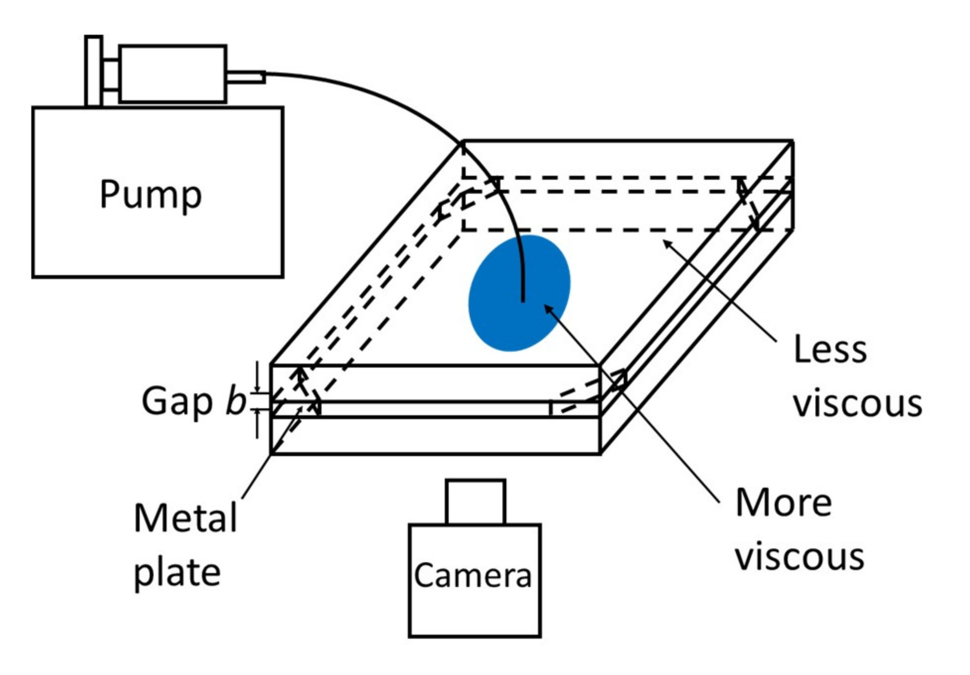
2.2. Displacement Experiment

We performed the fluid displacement under hydrodynamically stable conditions, i.e., a more viscous fluid displaced a less viscous one. The schematic for the fluid displacement is shown in Figure 4. Hele-Shaw cells were used instead of porous media because the Hele-Shaw cell consists of a thin gap between two parallel glass plates and is the simplest two-dimensional model of porous media. The gap between the Hele-Shaw cells was fixed at 0.3 mm. First, we filled up the cell with the less viscous Na2SO4 solution and then injected the more viscous PEG solution into the cell using a syringe pump. The PEG solutions were dyed blue to visualize the experimental process. The displacement experiments were recorded by a video camera from the bottom. The injection flow rate of the more viscous liquid was fixed as 3.35 mL/h. All experiments were performed at room temperature (25 ± 1 °C) and atmospheric pressure (approx. 1 atm).

2.3. Physical Property Measurements

The density of the solutions was measured using a pycnometer with an electric balance. However, the density effect can be ignored when using a horizontal Hele-Shaw cell and when the gap between the cells is small enough.
Another important property is interfacial tension between the displacing and displaced solutions. The interfacial tension was measured by a spinning drop tensiometer, SITE100 from KRÜSS, Germany. The interfacial tension measurement was carried out in a rotating horizontal capillary filled with a high-density liquid. A drop of low-density fluid was placed inside the liquid. Because the rotation of the horizontal capillary creates a centrifugal force, which is against the interfacial tension of the fluids, the drop elongates, making the drop radius smaller, until it reaches a certain radius where the interfacial tension and centrifugal force are balanced. This device calculates the interfacial tension of the system using the following equation:
γ = r 3 ω 2 Δ ρ 4 ,
where r (m) is the drop radius, ω (rad/s) is the angular frequency of rotation, and Δ ρ (kg/m3) is the density difference between the two fluids. Here, ω was fixed at 6000 rpm (628 rad/s).
The other important physical property is the viscosity of the solutions. The viscosity was measured using an AR-G2 rheometer from TA Instruments, New Castle, DE, USA. We measured shear viscosity to investigate the viscosity itself and confirmed whether our solutions were Newtonian using a cone–plate-type sensor.

3. Results and Discussion

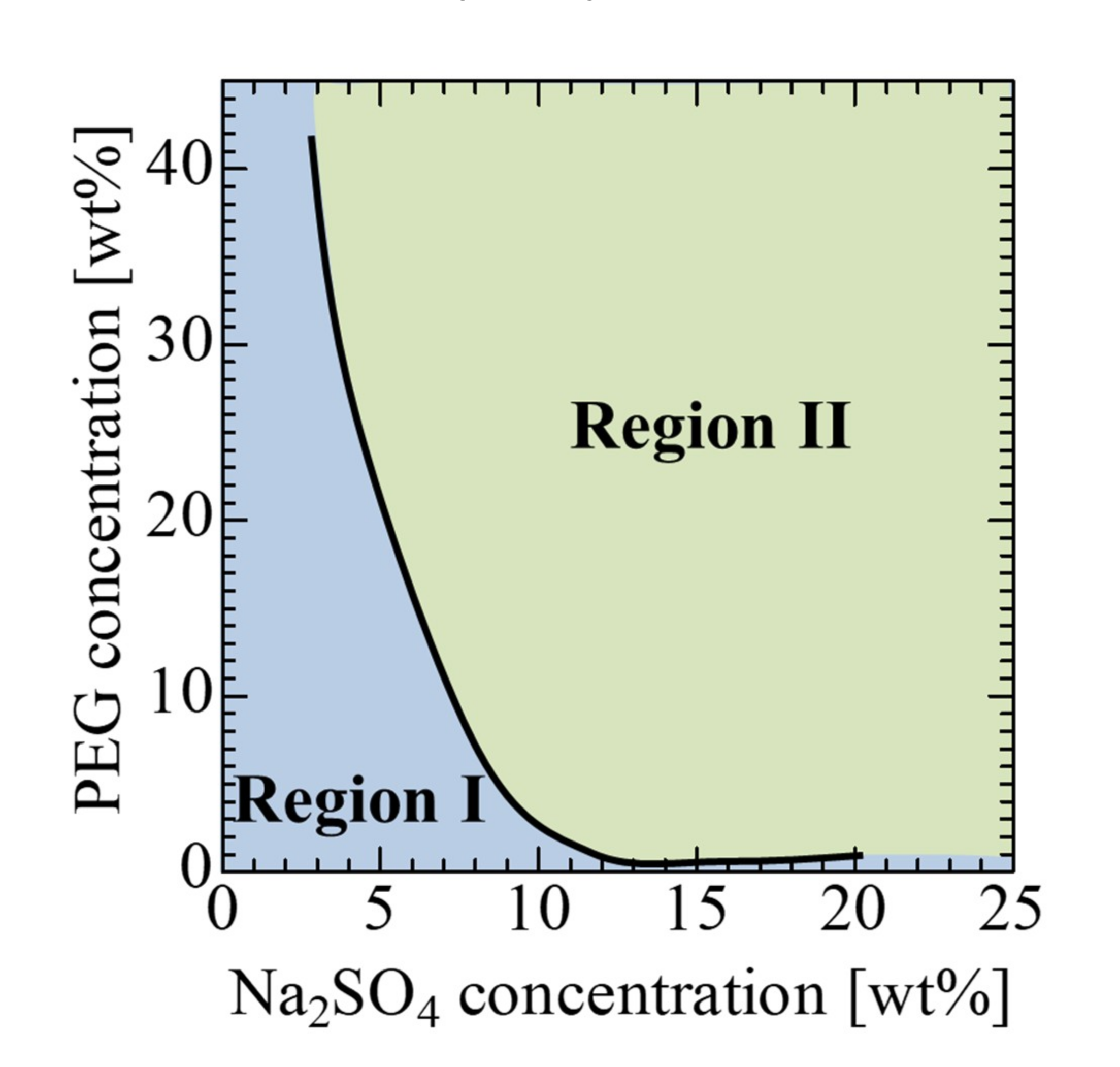
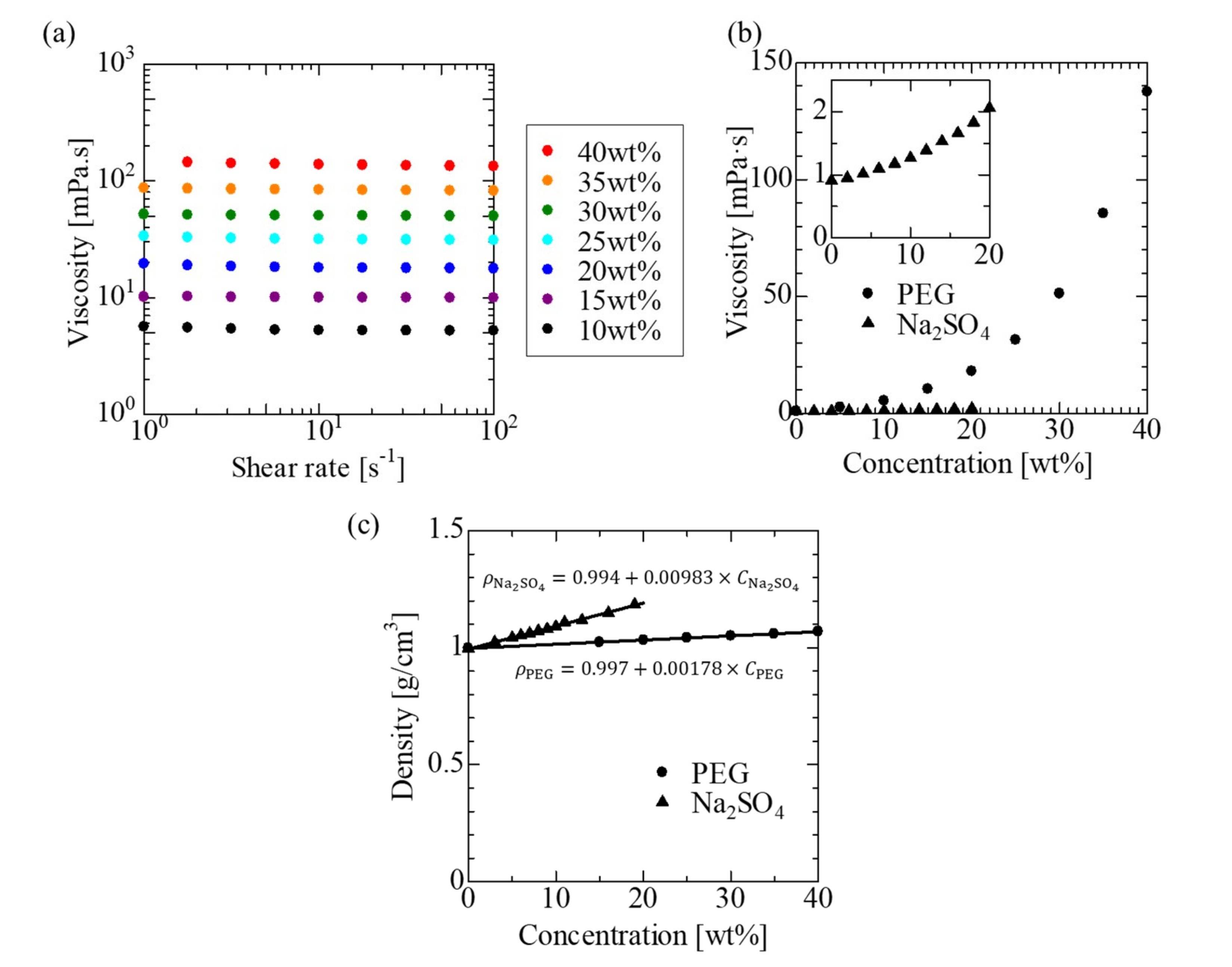
3.1. Physical Properties

The measured physical properties are shown in Figure 5. Figure 5a shows that the viscosities of PEG solutions are constant against shear rates, which means the PEG solutions are Newtonian. Figure 5b depicts the dependence of viscosity on the solute concentrations, and the inset shows the results of Na2SO4 for easy observation. The viscosities of PEG solutions depend greatly on the concentration of PEG, while the viscosities of Na2SO4 are very low compared to those of PEG solutions. Figure 5c shows the densities, which have a linear relationship with the concentration of the solution. In the horizontal Hele-Shaw cells, however, the density effect (gravitational effect) can be ignored when the gap between the cells is small enough.

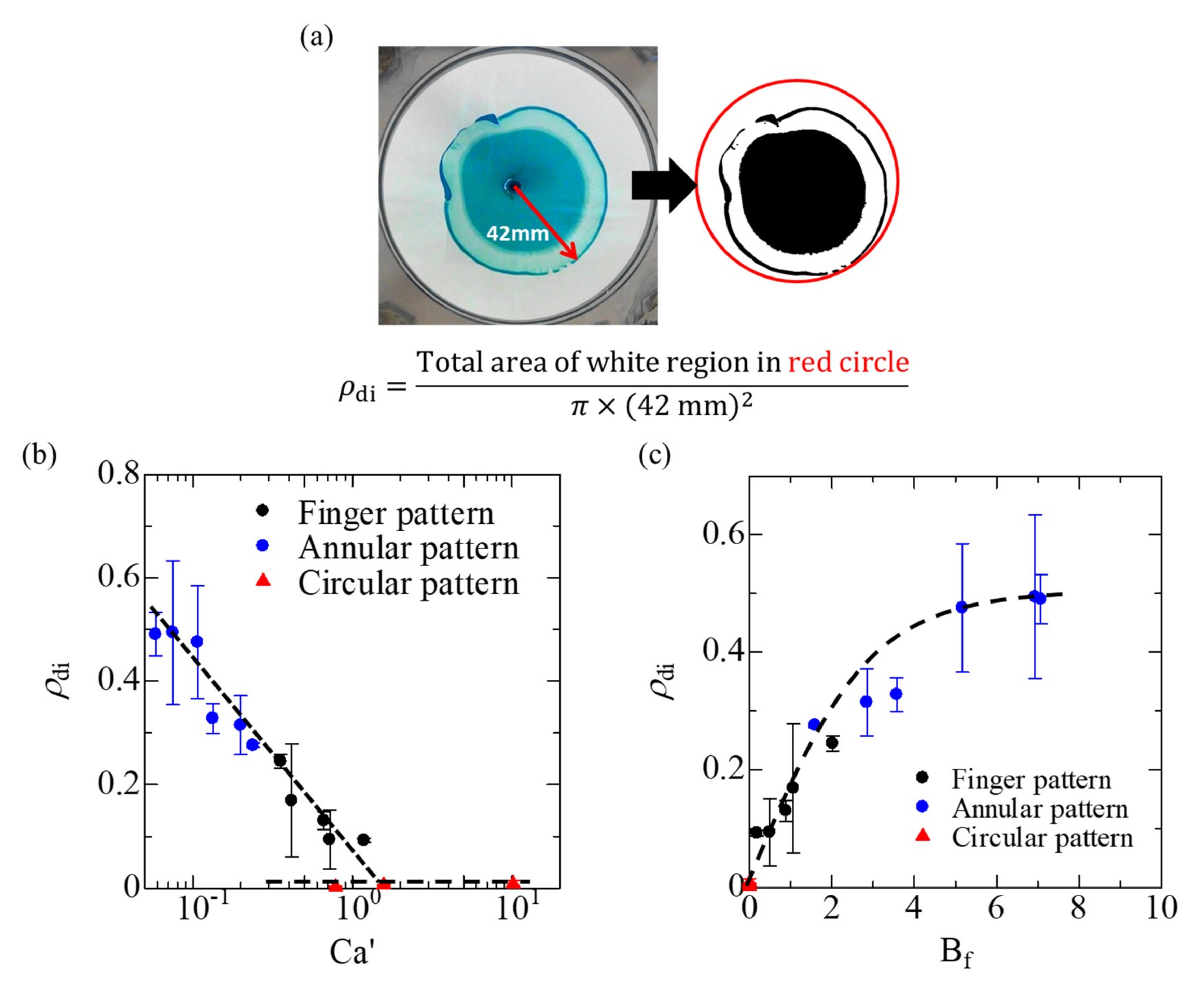
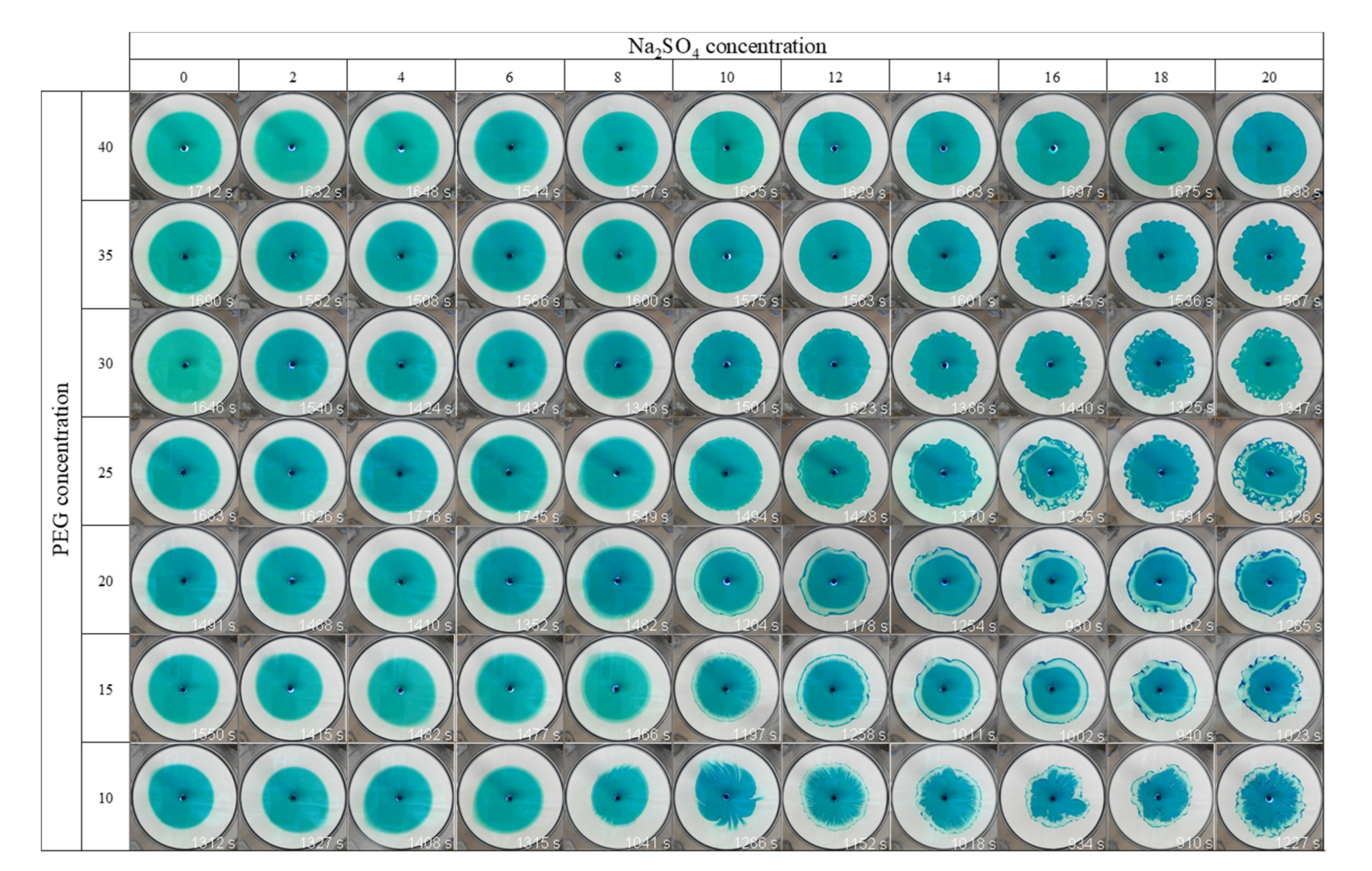
3.2. Fluid Displacements

We first investigated the pattern formation of three fluid systems during fluid displacement under different thermodynamic conditions and the same hydrodynamic conditions or different hydrodynamic conditions and similar thermodynamic conditions. System I is at 20 wt % PEG and 0 wt % Na2SO4, System II is at 20 wt % PEG and 20 wt % Na2SO4, and System III is at 40 wt % PEG and 20 wt % Na2SO4. System I lies in Region I, whereas Systems II and III lie in Region II in Figure 3. Figure 6a shows the time evolution of the pattern formation of System I. A circular pattern expands as time proceeds because System I is absent from the thermodynamic instability and hydrodynamic interfacial instability. Similarly, the immiscible system, which is thermodynamically and hydrodynamically stable, approaches a perfectly circular pattern because of the high interfacial tension. The displacement patterns in the immiscible system have already been reported in [10].
Figure 6b shows the time evolution of the pattern of System II. At the beginning of the formation, the color of the outer region of the displacing fluid changes from indigo blue to light blue at time t = 30 s. The color change means that water and Na2SO4 molecules diffuse from the interface into the displacing fluid to reduce the PEG concentration inside the diffusion region. At t = 50 s, many indigo blue domains newly form in the outermost part of the displacing fluid, and the light blue region is left inside the outer indigo domains to produce a light blue circular ring. The formation of the outer indigo blue domains and the light blue circular ring indicates the spontaneous formation of PEG-rich and Na2SO4-rich phases, respectively. The interface becomes distorted, and the annular-like pattern expands with distortion as time proceeds. System I has a similar viscous ratio to System II because the viscous ratio depends on the PEG concentration, as shown in Figure 5b. Thus, thermodynamic instability, i.e., phase separation, is estimated to contribute to the spontaneous formation of the outer indigo domains and to the distorted interfacial pattern.
The pattern formation of System III is shown in Figure 6c. The outer region of the displacing fluid becomes distorted without a color change, and the distorted interface grows continuously. System III is comparable in the extent of thermodynamic instability to System II because both fluid systems lie in Region II at the same Na2SO4 concentration, but they are different in terms of their viscous ratio. A high viscous ratio restricts the diffusion region to the periphery of the displacing fluid. Thus, phase separation occurs at the outmost interface of the displacing fluid, inducing the interfacial distortion. This fingering-like pattern is already reported by Suzuki et al. [10]. The distorted interfacial pattern is created by the Korteweg force exerted in a direction toward the higher region of PEG concentration [10]. Thus, the pattern of System II is a phase separation-dominated displacement in comparison with System III, where the process of viscous dissipation weakens the phase separation effect.
Figure 7 shows the results of the hydrodynamically stable displacement using various composition combinations. A circular, stable pattern forms as PEG concentration increases and Na2SO4 concentration decreases, i.e., the composition goes to the upper left in Figure 7. In contrast, the finger-like pattern forms as PEG concentration decreases and Na2SO4 concentration increases, i.e., the composition moves to the lower right in Figure 7. For PEG concentrations higher than 30 wt %, the light blue circular ring disappears, and the outer indigo blue interface becomes distorted. As the Na2SO4 concentration increases, the interface becomes sharp because the interfacial tension increases with the increase in Na2SO4 concentration [31].
It is reported that the Korteweg force becomes stronger as the concentration of Na2SO4 increases [10,31]. As shown in Figure 5b, the viscosity decreases as the concentration of PEG solution decreases, which means that the solutions with less viscosity easily move, and phase separation is thought to easily occur.
Figure 8 shows the fluid displacement patterns with the phase diagram shown in Figure 3. The curve in the figure is from [36] and indicates the boundary between fully miscible and partially miscible zones. The patterns are categorized into three types: the circular pattern (), the finger-like pattern (), and the annular-like pattern () in Figure 8. If we pay close attention to the boundary between the finger-like pattern () and the annular-like pattern (), both PEG and Na2SO4 concentrations are related to the pattern formation, which means that the morphologies are affected by the complexity of the hydrodynamic effect, such as the viscosity and thermodynamic effect such as phase separation. On the other hand, the patterns are circular () when the Na2SO4 concentration is less than 5 wt % in Figure 8, regardless of the PEG and Na2SO4 concentrations, because the displacement patterns are determined only by the hydrodynamic effect of viscosity.
The extent of the phase separation can be expressed by the progression of the phase separation. The progression of the phase separation can be considered from the growth rate of the interfacial tension (IFT) because the formation of an interface due to phase separation induces the increase in interfacial free energy. Figure 9a shows the time evolution of IFT between 20 wt % Na2SO4 solution and PEG solutions with several concentrations. IFT, at all concentration ranges, increases with time. The steady value of the IFT increases with the decrease in PEG concentration. The IFT of the fully miscible systems decreases with time because the width of the interface becomes wider due to molecular diffusion [10]. In contrast, the IFT of partially miscible systems increases with time because the interface becomes sharp due to phase separation. Figure 9b depicts the rate constant, k, defined as γ = γ 0 γ e k t + γ , where γ 0 and γ are initial and steady values of IFT in Figure 9a, respectively. The relaxation process of IFT corresponds to that of phase separation. Therefore, the rate constant, k , is thought to represent the progress of phase separation. The rate is higher with the decrease in PEG concentration because the formation rate of the interface decreases with the increase in the viscosity of the displacing fluid. Therefore, the progress of phase separation is important for forming patterns, for example, the annular-like pattern (Figure 6b) for high rates and the finger-like patterns (Figure 6c) for low rates. Moreover, the progression is affected by the mobility-like viscosity contrast, and the viscosity is affected by the concentrations of the components (here, PEG). Thus, we compared the patterns using a dimensionless number considering those effects, such as modified capillary number, Ca , including the viscosity, interfacial tension, and flow rate.
In order to explore the factors on which the fluid displacement patterns depend, we evaluated the effects of physicochemical and hydrodynamic properties on the patterns using two dimensionless numbers: the well-known capillary number, C a , and the newly defined body force number, B f . The modified capillary number, Ca , is defined as Ca = μ q b 2 γ , where μ (Pa·s) is viscosity, q (m3/s) is the flow rate, b (m) is the gap between the cells, and γ (N/m) is an interfacial tension between displacing and displaced liquids [37,38,39,40,41]. It is noted that Ca at fully miscible systems cannot be defined because IFT in the fully miscible systems is almost zero. A dimensionless number, B f , represents the relative effect of the body force driven by thermodynamic instability versus the pressure gradient related to Darcy’s law, which was introduced in [10]:
B f = Δ γ 2 π r m b μ V κ = Δ γ b 2 μ q ,
where Δ γ = γ * γ 0 , γ 0 is the initial value of the measured interfacial tension, γ * is interfacial tension at a time when the longest radius, r m , reaches 42 mm, κ ( = b 2 /12) is the permeability of the Hele-Shaw cell, μ is the viscosity of the displacing fluid, V ( = q / 2 π r m b ) is linear velocity, and q is the injected flow rate. We neglected the numerical coefficient on the right-hand side for simplicity. We introduced a deformation index as a quantitative evaluation index for the extent of interfacial deformation. The index, ρ di , is defined as the white area involving areas of Na2SO4-rich regions generated by phase separation and created by deformation, divided by the area of a circle with maximum radius of 42 mm as shown in Figure 10a. Here, we measured the patterns of the immiscible system, the conditions of which are described in [10], to better understand the mechanism of the pattern formation of all cases. The ρ di of the immiscible system is almost zero because the patterns are perfectly circular, as mentioned in the Introduction.
Figure 10b shows the relationship between the deformation index and Ca in the partially miscible and the immiscible systems. The value of ρ di decreases with increasing Ca , but the immiscible system indicates that the value of ρ di remains at zero regardless of Ca because the displacement of the immiscible system is hydrodynamically and thermodynamically stable. Thus, the well-known Ca is not appropriate for a comprehensive analysis of the fluid displacement using various types of fluid systems. Therefore, we investigated the relationship between ρ di and the newly defined B f . For the immiscible system, IFT cannot change with time because the system is under thermodynamic equilibrium, and the value of B f is zero. Figure 10c shows the relationship between ρ di and B f . The value of ρ di increases with increasing B f , and the patterns change from circular to finger-like to annular-like patterns. The data of the patterns seem to collapse well onto a single curve, even with the immiscible patterns with the variation in B f , which is not with the case for the effects on Ca . This relation indicates that, as the thermodynamic instability is dominant over the viscous dissipation, the degree of deformation becomes larger. The increase in IFT due to phase separation enhances the interface deformation because the increase in IFT corresponds to the increase in Korteweg force, which is a driving force for spontaneous convection. The pattern formation is attributed to the combination of the hydrodynamic effect (viscosity), molecular diffusion, and phase separation (thermodynamic effect). Because B f includes these effects, the ρ di can be expressed as a function of B f on a single curve, regardless of the miscibility.

4. Conclusions

We investigated the deformation index of various patterns such as circular, finger-like, and annular-like patterns during fluid displacement, while changing the progression of phase separation using the newly defined dimensionless number, B f . The fully miscible cases under the hydrodynamically stable displacement condition, where the more viscous PEG solution displaces the less viscous Na2SO4 solution, show constant circular patterns. For the partially miscible systems, phase separation occurs at the interface between displacing and displaced solutions, creating a separated region with domain growth for the annular patterns and creating a deformed interface for the finger pattern. Moreover, the deformation index of the patterns can be scaled with B f , which involves viscous dissipation, molecular diffusion, and phase separation. Therefore, the patterns in the partially miscible systems are proved to be formed by the competition of viscous dissipation and phase separation. B f is a crucial factor to describe the complex morphologies induced by the fluid displacement in partially miscible systems. The investigated morphologies and B f will directly contribute to predicting and/or controlling CO2-enhanced oil recovery, where more viscous water displaces less viscous CO2 under the ground, the conditions of which are partially miscible.

Author Contributions

Experiments, R.T. and R.X.S.; discussion and review, R.X.S., R.T., Y.N., M.M., and T.B.; writing, R.X.S. and T.B. All authors have read and agreed to the published version of the manuscript.

Funding

This is study was supported by JSPS KAKENHI Grant No. 19J12553.

Conflicts of Interest

The authors declare no conflict of interest.

References

  1. Broyles, B.S.; Shalliker, R.A.; Cherrak, D.E.; Guiochon, G. Visualization of viscous fingering in chromatographic columns. J. Chromatogr. A 1998, 822, 173–187. [Google Scholar] [CrossRef]
  2. Bhaskar, K.R.; Garik, P.; Turner, B.S.; Bradley, J.D.; Bansil, R.; Stanley, H.E.; LaMont, J.T. Viscous fingering of HCl through gastric mucin. Nature 1992, 360, 458–461. [Google Scholar] [CrossRef] [PubMed]
  3. Nordbotten, J.M.; Celia, M.A.; Bachu, S. Injection and storage of CO2 in deep saline aquifers: Analytical solution for CO2 plume evolution during injection. Transp. Porous Media 2005, 58, 339–360. [Google Scholar] [CrossRef]
  4. Pojman, J.A.; Gunn, G.; Patterson, C.; Owens, J.; Simmons, C. Frontal dispersion polymerization. J. Phys. Chem. B 1998, 102, 3927–3929. [Google Scholar] [CrossRef]
  5. Lake, L.W.; Johns, R.T.; Rossen, W.R.; Pope, G.A. Fundamentals of Enhanced Oil Recovery; Society of Petroleum Engineers: Richardson, TX, USA, 2014; ISBN 978-1-61399-328-6. [Google Scholar]
  6. Saffman, P.G.; Taylor, G. The penetration of a fluid into a porous medium or Hele-Shaw cell containing a more viscous liquid. Proc. R. Soc. A 1958, 245, 312–329. [Google Scholar] [CrossRef]
  7. Homsy, G.M. Viscous fingering in porous media. Annu. Rev. Fluid Mech. 1987, 19, 271–311. [Google Scholar] [CrossRef]
  8. Darcy, H.P.G. Les Fontaines Publiques de la Ville de Dijon; Victor Dalmont: Paris, France, 1856. [Google Scholar]
  9. Wyckoff, R.D.; Botset, H.G.; Muskat, M.; Reed, D.W. The measurement of the permeability of porous media for homogeneous fluids. Rev. Sci. Instrum. 1933, 4, 394–405. [Google Scholar] [CrossRef]
  10. Suzuki, R.X.; Nagatsu, Y.; Mishra, M.; Ban, T. Fingering pattern induced by spinodal decomposition in hydrodynamically stable displacement in a partially miscible system. Phys. Rev. Fluids 2019, 4, 104005. [Google Scholar] [CrossRef]
  11. McCloud, K.V.; Maher, J.V. Experimental perturbations to Saffman-Taylor flow. Phys. Rep. 1995, 260, 139–185. [Google Scholar] [CrossRef]
  12. Nagatsu, Y. Viscous fingering phenomena with chemical reactions. Curr. Phys. Chem. 2015, 5, 52–63. [Google Scholar] [CrossRef]
  13. De Wit, A. Chemo-hydrodynamic patterns in porous media. Philos. Trans. R. Soc. A Math. Phys. Eng. Sci. 2016, 374, 20150419. [Google Scholar] [CrossRef] [PubMed]
  14. De Wit, A. Chemo-hydrodynamic patterns and instabilities. Annu. Rev. Fluid Mech. 2020, 52, 531–555. [Google Scholar] [CrossRef] [Green Version]
  15. Chan, C.K.; Liang, N.Y. Observations of surfactant driven instability in a Hele-Shaw cell. Phys. Rev. Lett. 1997, 79, 4381–4384. [Google Scholar] [CrossRef]
  16. Krechetnikov, R.; Homsy, G.M. On a new surfactant-driven fingering phenomenon in a Hele-Shaw cell. J. Fluid Mech. 2004, 509, 103–124. [Google Scholar] [CrossRef] [Green Version]
  17. Fernandez, J.; Krechetnikov, R.; Homsy, G.M. Experimental study of a surfactant-driven fingering phenomenon in a Hele-Shaw cell. J. Fluid Mech. 2005, 527, 197–216. [Google Scholar] [CrossRef] [Green Version]
  18. Tang, H.; Grivas, W.; Homentcovschi, D.; Geer, J.; Singler, T. Stability considerations associated with the meniscoid particle band at advancing interfaces in Hele-Shaw suspension flows. Phys. Rev. Lett. 2000, 85, 2112–2115. [Google Scholar] [CrossRef]
  19. Bihi, I.; Baudoin, M.; Butler, J.E.; Faille, C.; Zoueshtiagh, F. Inverse Saffman-Taylor experiments with particles lead to capillarity driven fingering instabilities. Phys. Rev. Lett. 2016, 117, 034501. [Google Scholar] [CrossRef] [Green Version]
  20. Xu, F.; Kim, J.; Lee, S. Particle-induced viscous fingering. J. Nonnewton. Fluid Mech. 2016, 238, 92–99. [Google Scholar] [CrossRef]
  21. Kim, J.; Xu, F.; Lee, S. Formation and destabilization of the particle band on the fluid-fluid interface. Phys. Rev. Lett. 2017, 118, 074501. [Google Scholar] [CrossRef]
  22. Podgorski, T.; Sostarecz, M.C.; Zorman, S.; Belmonte, A. Fingering instabilities of a reactive micellar interface. Phys. Rev. E 2007, 76, 016202. [Google Scholar] [CrossRef] [Green Version]
  23. Gérard, T.; De Wit, A. Miscible viscous fingering induced by a simple A+B→C chemical reaction. Phys. Rev. E 2009, 79, 016308. [Google Scholar] [CrossRef] [PubMed] [Green Version]
  24. Nagatsu, Y.; De Wit, A. Viscous fingering of a miscible reactive A + B → C interface for an infinitely fast chemical reaction: Nonlinear simulations. Phys. Fluids 2011, 23, 043103. [Google Scholar] [CrossRef] [Green Version]
  25. Riolfo, L.A.; Nagatsu, Y.; Iwata, S.; Maes, R.; Trevelyan, P.M.J.; De Wit, A. Experimental evidence of reaction-driven miscible viscous fingering. Phys. Rev. E 2012, 85, 015304. [Google Scholar] [CrossRef] [PubMed] [Green Version]
  26. Nagatsu, Y.; Ishii, Y.; Tada, Y.; De Wit, A. Hydrodynamic fingering instability induced by a precipitation reaction. Phys. Rev. Lett. 2014, 113, 024502. [Google Scholar] [CrossRef] [Green Version]
  27. Mishra, M.; Trevelyan, P.M.J.; Almarcha, C.; De Wit, A. Influence of double diffusive effects on miscible viscous fingering. Phys. Rev. Lett. 2010, 105, 204501. [Google Scholar] [CrossRef] [Green Version]
  28. Fu, X.; Cueto-Felgueroso, L.; Juanes, R. Thermodynamic coarsening arrested by viscous fingering in partially miscible binary mixtures. Phys. Rev. E 2016, 94, 033111. [Google Scholar] [CrossRef] [Green Version]
  29. Amooie, M.A.; Soltanian, M.R.; Moortgat, J. Hydrothermodynamic mixing of fluids across phases in porous media. Geophys. Res. Lett. 2017, 44, 3624–3634. [Google Scholar] [CrossRef]
  30. Fu, X.; Cueto-Felgueroso, L.; Juanes, R. Viscous fingering with partially miscible fluids. Phys. Rev. Fluids 2017, 2, 104001. [Google Scholar] [CrossRef] [Green Version]
  31. Suzuki, R.X.; Nagatsu, Y.; Mishra, M.; Ban, T. Phase separation effects on a partially miscible viscous fingering dynamics. J. Fluid Mech. 2020, 898, A11. [Google Scholar] [CrossRef]
  32. Korteweg, D.J. Sur la forme que prennent les équations du mouvement des fluides si l’on tient compte des forces capillaires cauśees par des variations de densité. Arch. Néerl. Sci. Exactes Nat. 1901, 6, 1–24. [Google Scholar]
  33. Molin, D.; Mauri, R. Enhanced heat transport during phase separation of liquid binary mixtures. Phys. Fluids 2007, 19, 074102. [Google Scholar] [CrossRef] [Green Version]
  34. Budroni, M.A.; Riolfo, L.A.; Lemaigre, L.; Rossi, F.; Rustici, M.; De Wit, A. Chemical control of Hydrodynamic instabilities in partially miscible two-layer systems. J. Phys. Chem. Lett. 2014, 5, 875–881. [Google Scholar] [CrossRef] [PubMed] [Green Version]
  35. Budroni, M.A.; Thomas, C.; De Wit, A. Chemical control of dissolution-driven convection in partially miscible systems: Nonlinear simulations and experiments. Phys. Chem. Chem. Phys. 2017, 19, 7936–7946. [Google Scholar] [CrossRef] [PubMed]
  36. Snyder, S.M.; Cole, K.D.; Sziag, D.C. Phase compositions, viscosities, and densities for aqueous two-phase systems composed of polyethylene glycol and various salts at 25 °C. J. Chem. Eng. Data 1992, 37, 268–274. [Google Scholar] [CrossRef]
  37. Rauseo, S.N.; Barnes, P.D.; Maher, J.V. Development of radial fingering patterns. Phys. Rev. A 1987, 35, 1245–1251. [Google Scholar] [CrossRef]
  38. Chen, J.D. Growth of radial viscous fingers in a Hele-Shaw cell. J. Fluid Mech. 1989, 201, 223–242. [Google Scholar] [CrossRef] [Green Version]
  39. Fernandez, J.; Homsy, G.M. Viscous fingering with chemical reaction: Effect of in-situ production of surfactants. J. Fluid Mech. 2003, 480, 267–281. [Google Scholar] [CrossRef]
  40. Tsuzuki, R.; Ban, T.; Fujimura, M.; Nagatsu, Y. Dual role of surfactant-producing reaction in immiscible viscous fingering evolution. Phys. Fluids 2019, 31, 022102. [Google Scholar] [CrossRef]
  41. Tsuzuki, R.; Tanaka, R.; Ban, T.; Nagatsu, Y. Deviation from capillary number scaling of nonlinear viscous fingering formed by the injection of Newtonian surfactant solution. Phys. Fluids 2019, 31, 042108. [Google Scholar] [CrossRef]
Figure 1. Fluid displacements for (a) a hydrodynamically stable condition of the interface, (b) a hydrodynamically unstable condition of the interface. The blue solution displaces the surrounding white solution. A more viscous solution is displacing a less viscous one in (a) while a less viscous solution is displacing a more viscous one in (b). The patterns like fingering in (b) are called “Saffman–Taylor instability” or “viscous fingering” (VF).
Coatings 10 00960 g001
Figure 2. The explanation for Saffman–Taylor instability. The solution flows from left to right in the figures. (a) The setup situation and the results under (b) a hydrodynamically stable condition ( μ 1 > μ 2 ) and (c) a hydrodynamically unstable condition ( μ 1 < μ 2 ), i.e., Saffman–Taylor instability. p represents pressure at the position z .
Coatings 10 00960 g002
Figure 3. Phase diagram of polyethylene glycol (PEG)–Na2SO4–water system.
Coatings 10 00960 g003
Figure 4. The schematic for the hydrodynamically stable displacement.
Coatings 10 00960 g004
Figure 5. (a) Viscosity of PEG solutions against shear rate, (b) viscosity of PEG and Na2SO4 solutions against concentration, (inset) viscosity of Na2SO4 solutions against concentrations, (c) density of PEG and Na2SO4 solutions against concentrations.
Coatings 10 00960 g005
Figure 6. Time evolution of the pattern formation at (a) System I, where 20 wt % PEG solution displaces 0 wt % Na2SO4 solution; (b) System II, where 20 wt % PEG solution displaces 20 wt % Na2SO4 solution; and (c) System III, where 35 wt % PEG solution displaces 20 wt % Na2SO4 solution.
Coatings 10 00960 g006
Figure 7. The results of the hydrodynamically stable displacement. The time shown in the right bottom corner is the time when the longest radius reached 42 mm.
Coatings 10 00960 g007
Figure 8. Phase diagram of the displacement patterns.
Coatings 10 00960 g008
Figure 9. (a) Time evolution of the interfacial tension between PEG solutions and 20 wt % Na2SO4 solution; (b) the phase separation rate constant, k, of (a).
Coatings 10 00960 g009
Figure 10. (a) The definition of ρ di . (b) The relationship between the modified capillary number, Ca , and the ρ di for the patterns. (c) The pattern evaluation with B f . The fitted curves are for a better visualization of the effects of Ca and B f .
Coatings 10 00960 g010
Table 1. The solution system used.
Displacing More Viscous LiquidDisplaced Less Viscous Liquid
0 wt % Na2SO4 solution
2 wt % Na2SO4 solution
10 wt % PEG solution4 wt % Na2SO4 solution
15 wt % PEG solution6 wt % Na2SO4 solution
20 wt % PEG solution8 wt % Na2SO4 solution
25 wt % PEG solution10 wt % Na2SO4 solution
30 wt % PEG solution12 wt % Na2SO4 solution
35 wt % PEG solution14 wt % Na2SO4 solution
40 wt % PEG solution16 wt % Na2SO4 solution
18 wt % Na2SO4 solution
20 wt % Na2SO4 solution
Phase LPhase H

