Article

Numerical Analysis of Carbon Nanotube-Based Nanofluid Unsteady Flow Amid Two Rotating Disks with Hall Current Coatings and Homogeneous–Heterogeneous Reactions

1
Department of Computer Science, Bahria University, Islamabad 44000, Pakistan
2
Department of Mechanical Engineering, Sejong University, Seoul 143-747, Korea
3
Department of Mathematics and Computer Science, Faculty of Science, Beirut Arab University, Beirut 115020, Lebanon
4
Department of ICT Convergence Rehabilitation Engineering, Soonchunhyang University, Asan 31538, Korea
5
Department of Computer Science and Engineering, Soonchunhyang University, Asan 31538, Korea
6
College of Natural and Health Sciences, Zayed University, Abu Dhabi 144543, UAE
*
Authors to whom correspondence should be addressed.
Coatings 2020, 10(1), 48; https://doi.org/10.3390/coatings10010048
Submission received: 20 November 2019 / Revised: 21 December 2019 / Accepted: 4 January 2020 / Published: 5 January 2020
(This article belongs to the Special Issue Recent Trends in Coatings and Thin Film–Modeling and Application)

Abstract

:
In the present exploration, our objective is to investigate the importance of Hall current coatings in the establishment of Cattaneo–Christov (CC) heat flux model in an unsteady aqueous-based nanofluid flow comprising single (SWCNTs) and multi-walled (MWCNTs) carbon nanotubes (CNTs) amid two parallel rotating stretchable disks. The novelty of the presented model is strengthened with the presence of homogeneous-heterogeneous (HH) reactions and thermal stratification effects. The numerical solution of the system of coupled differential equations with high nonlinearity is obtained by applying the bvp4c function of MATLAB software. To corroborate the authenticity of the present envisioned mathematical model, a comparison table is added to this study in limiting case. An excellent harmony between the two results is obtained. Effects of numerous parameters on involved distributions are displayed graphically and are argued logically in the light of physical laws. Numerical values of coefficient of drag force and Nusselt number are also tabulated for different parameters. It is observed that tangential velocity (function of rotation parameter) is increasing for both CNTs. Further, the incremental values of thermal stratification parameter cause the decrease in fluid temperature parameter.

Graphical Abstract

1. Introduction

Nanofluids consist of solid particles called nanoparticles with higher thermal characteristics suspended in some base fluid. Moreover, convective heat transfer through nanoparticles has motivated many researchers for its industrial applications, pharmaceutical processes, domestic refrigerators, chillers, heat exchangers, electronic cooling system, and radiators, etc., [1]. Nanofluids are considered as the finest coolants for its various industrial applications. Nanofluids exhibit promising thermos-physical properties e.g., they have small viscosity and density and large thermal conductivity and specific heat [2]. As far as transportation of energy is concerned, the ideal features of nanofluids are the high thermal conduction and low viscosity [3]. Choi and Eastman [4] primarily examined the upsurge in thermal conductivity by submerging nanoparticles into the ordinary fluid. Because of these thermos-physical characteristics, nanofluids are considered as the finest coolants that can work at various temperature ranges [5]. Sheikholeslami et al. [6] found a numerical solution ferrofluid flow under the influence of applied magnetic field in a hot elliptic cylinder. It is examined by them that strong Lorentz force is a source in declining the temperature of the fluid. The water-based nanofluid flow with numerous magnetite nanoparticles amid two stretchable rotating disks is numerically studied by Haq et al. [7]. Khan et al. [8] numerically addressed the water and ethylene glycol based nanofluid flow containing copper nanoparticles with suction/injection effect between parallel rotating stretchable disks. Saidi and Tamim [9] examined the pressure drop and heat transfer properties of nanofluid flow induce amid parallel stretchable disks in rotation by considering thermophoresis effects. Hayat et al. [10] also found a series solution of Jeffrey nanofluid flow between two coaxial rotating stretchable disks having convective boundary condition. Pourmehran et al. [11] numerically simulated the nanofluid flow between coaxial stretchable rotating disks.
Molecules of carbon atoms arranged in a cylindrical shape to form a structure called carbon nanotubes (CNTs). This arrangement of the molecule may be by rolling up of single sheet or by multiple sheets of graphene [12]. The novel properties of CNTs are light weight and high thermal conductivity, which make them potentially useful. CNTs are not dangerous to the environment as they are composed of carbon atoms [13]. The CNTs are the most desirous materials of the twenty-first century. Modern applications of CNTs are in microfabrication technique, pancreatic cancer test, and tissue engineering, etc., [14]. The flow of nanofluid containing both types CNTs with thermal radiation and convective boundary condition effects is examined analytically by Imtiaz et al. [15]. The water-based nanofluid flow containing CNTs of both categories under the impact of magneto-hydrodynamics (MHD) amid two parallel disks is studied by Haq et al. [16]. Mosayebidorcheh et al. [17] did heat transfer analysis with thermal radiation impacts of CNTs-based nanofluid squeezing flow between two parallel disks numerically via the least square method. Effects of thermal radiation in a magnetic field comprising both types of CNTs aqueous based nanofluid flow by two rotating stretchable disks are debated by Jyothi et al. [18]. Transparent carbon nanotubes coating to obtain conductive transparent coating is analyzed by Kaempgen [19]. Keefer et al. [20] studied carbon nanotube-coated electrodes to improve the current electrophysiological techniques. Enzyme-coated carbon nanotube as a single molecule biosensor was reported by Besteman et al. [21]. Some recent investigations featuring Carbon nanotubes amalgamated fluid flow may be found in [22,23,24,25,26,27,28,29,30] and many therein.
Thermal energy transformation possesses significant importance in engineering applications such as fuel cell efficiency, biomedical applications including cooling of electronic devices, heat conduction in tissues, energy production, heat exchangers, and cooling towers etc., [31]. Classical Fourier law of heat conduction was employed to describe the mechanism of heat transfer. But this model gives parabolic energy equation that is medium encountered initial disturbance instantly which is called “heat conduction paradox.” Cattaneo [32] tackled this enigma by introducing the time needed for the conduction of heat via thermal waves at a limited speed which is known as thermal relaxation time. The modification in Fourier law gives hyperbolic energy equation for temperature profile. Christov [33] further inserted Oldroyd’s upper convective derivative to maintain material invariant formulation. This upgraded model is known as Cattaneo- Christov heat flux model. The aqueous fluid flow by two rotating disks with the impact of CC heat flux is studied by Hayat et al. [34]. Dogonchi et al. [35] scrutinized the squeezed flow of nanofluid encompassing CC heat flux and thermal radiation effects. Lu et al. [36] discussed the unsteady squeezing nanofluid flow between parallel disks comprising CNTs with CC heat flux model and HH reactions. The recent advance studies on CC heat flux is done by many researchers [37,38,39,40].
The aforementioned literature survey (Table 1) reveals that unsteady nanofluid flow containing CNTs with CC heat flux under the influence of hall current between two rotating stretchable disks is not yet discussed. Additional impacts like HH reactions and thermal stratification of the presented mathematical model may be considered as added features toward the novelty of the problem. The problem is solved numerically by using the bvp4c function of MATLAB software.

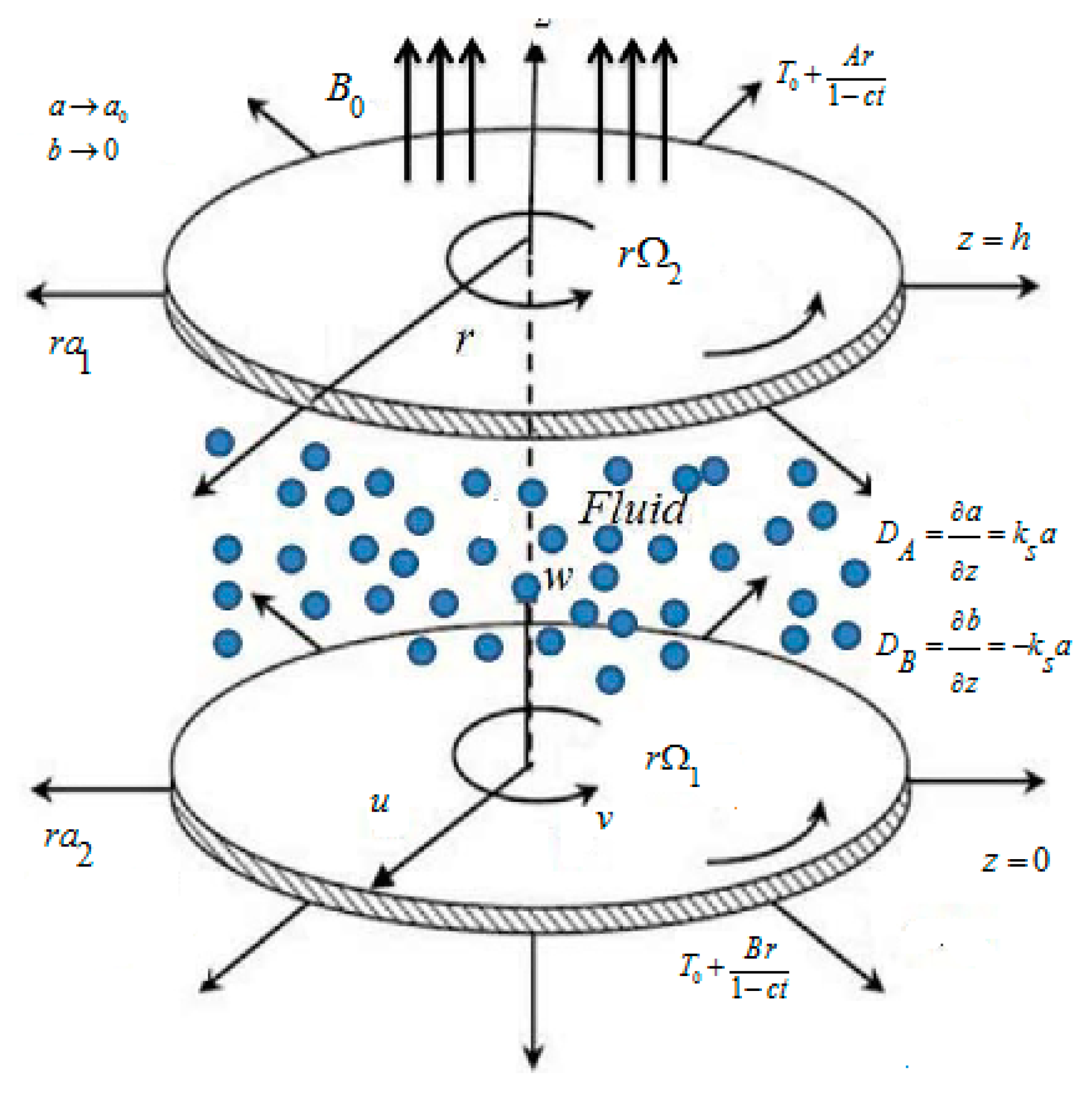
2. Problem Formulation

Consider an axisymmetric unsteady MHD water base nanofluid flow between continuously stretchable disks with hall current effect amid non-conducting rotating disks at z = 0 and z = h . The disks rotate at constant angular velocities Ω 1 and Ω 2 about its axis. Magnetic field B 0 that is uniformly distributed is applied in the normal direction of the disks (Figure 1). Furthermore, the stretching rates of the disks are a 1 and a 2 . Temperature T 2 = T 0 + B r 1 c t refers to the temperature of upper disk while the disk’s temperature at z = h is T 1 = T 0 + A r 1 c t in a thermally stratified medium.
For isothermal cubic autocatalysis, a model for homogeneous and heterogeneous reactions with reactants as chemical species are A * and   B * and was proposed by Merkin and Chaudary [41] and is given by:
A * + 2 B * 3 B * , r a t e = K c = a b 2 ,
A * B * ,   r a t e = K s a ,
The continuity equation is
. V = 0 ,
The momentum equations are
u t + ( V . ) u = 1 ρ n f p r * + μ n f ρ n f ( 2 u ) σ n f ρ n f B O 2 1 + m 2 ( u m v ) ,
v t + ( V . ) v = μ n f ρ n f ( 2 v ) σ n f ρ n f B O 2 1 + m 2 ( v + m u ) ,
w t + ( V . ) w = 1 ρ n f p z * + μ n f ρ n f + 2 w ,
The relevant energy equation is
( ρ C p ) n f ( V . ) T = . q ,
where T represents the temperature, C p the specific heat and q the heat flux. Heat flux in perspective of Cattaneo–Christov expression is satisfied.
q + ϵ 1 ( q t + V . ( q ) q . ( V ) + ( . V ) q ) k T .
Here, ϵ 1 is the thermal relaxation time and k is the thermal conductivity. Utilizing the incompressibility condition, we arrive at
q + ϵ 1 ( q t + V . ( q ) q . V ) k T .
Eliminating q from Equations (9) and (7), we get
T t + u T r + w T z + ϵ 1 ( T t t + u t T r + 2 u T t r + 2 w T t z + w t T z + u u r T r + w w z T z + u w r T r + w T r T z + 2 u w T t z + u 2 w r r + w 2 T z z = K n f ( ρ C p ) n f ( 2 T ) .
As V = ( u , v , w ) is the velocity vector, we obtain the following governing equations after applying the boundary layer theory:
u r + u r + w z = 0 ,
u t + u u r + w u z v 2 r = 1 ρ n f p r * + μ n f ρ n f ( u r r + 1 r u r u r 2 + u z z ) σ n f ρ n f B O 2 1 + m 2 ( u m v ) ,
v t + u v r + w v z + u v r = μ n f ρ n f ( v r r + 1 r v r v r 2 + v z z ) σ n f ρ n f B O 2 1 + m 2 ( v + m u ) ,
w t + u w r + w w z v 2 r = 1 ρ n f p z * + μ n f ρ n f ( w r r + 1 r w r + w z z ) ,
T t + u T r + w T z + ϵ 1 ( T t t + u t T r + 2 u T t r + 2 w T t z + w t T z + u u r T r + w w z T z + u w r T r + w T r T z + 2 u w T t z + u 2 w r r + w 2 T z z = K n f ( ρ C p ) n f ( T r r + 1 r T r + T z z ) ,
a t + u a r + w a z = D A ( a r r + 1 r a r + a z z ) K c a b 2 ,
b t + u b r + w b z = D B ( b r r + 1 r b r + b z z ) + K c a b 2 .
The associated boundary conditions are
  u = r a 1 1 c t ,   v = r Ω 1 1 c t , w = 0 , T = T 1 ( r ) = T 0 + A r 1 c t , D A a z = K s a , D B b z = K s a , at z = 0 ,
u = r a 2 1 c t ,   v = r Ω 2 1 c t , w = 0 , T = T 2 ( r ) = T 0 + B r 1 c t ,   a a 0   , b 0 ,   z = h .
Here, T 0 is the reference temperature. A   and   B are the dimensional constant with dimension [ T L 1 ] .
Thermo-physical properties of CNTS are represented in mathematical form as follows:
A = μ n f μ f = 1 ( 1 ϕ ) 2.5 ,
B = ρ n f ρ f = ( 1 ϕ ) + ρ C N T ρ f ϕ ,
C = ( ρ C p ) n f ( ρ C p ) f = ( 1 ϕ ) + ( ρ C p ) C N T ( ρ C p ) f ϕ ,
D = k n f k f = ( 1 ϕ ) + 2 ϕ k C N T k C N T k f l n k C N T + k f 2 k f ( 1 ϕ ) + 2 ϕ k f k C N T k f l n k C N T + k f 2 k f ,
σ n f σ f = 1 + 3 ϕ ( σ C N T σ f 1 ) ( σ C N T σ f + 2 ) ( σ C N T σ f 1 ) .  
Table 2 represents the thermos-physical characteristics of CNTs and H2O.
Following transformation are used to convert the above nonlinear partial differential equations to dimensionless ordinary differential equations.
u = r Ω 1 1 c t f ( η ) ,   v = r Ω 1 1 c t g ( η ) ,   w = 2 h Ω 1 1 c t f ( η ) , θ = T T 2 T 1 T o , p * = ρ Ω 1 ν ( 1 c t ) 2 ( P ( η ) + r 2 2 h 2 ε ) ,   η = z h 1 c t ,   a = c 0 φ ˜ , b = c 0 l ˜ .
Equation (11) is satisfied automatically, Equations (12) to (17) are transformed into the following form:
A 1 ( f + η 2 f ) + R e ( f 2 2 f f g 2 ) + ε σ n f σ f M R e ( f m g ) B ( 1 + m 2 ) = A B f ,
B A R e [ ( g + 1 2   η g ) A 1 + 2 ( f g f g ) ]   σ n f σ f M R e ( g + m f ) A ( 1 + m 2 ) = g ,
p * z = ( A 1 ( f + η f ) 4 f f ) B ( 1 c t ) R e 2 ( 1 c t ) A f ,
A 1 ( s + θ + 1 2 η θ ) + ( s + θ ) f 2 f θ + γ [ ( s + θ + 7 8 η θ ) + f ( f + 1 2 η f ) ( s + θ ) + 2 f ( s + θ + 1 2 η θ ) 4 f ( 1 2 η θ + 3 2 θ ) + ( f + η f ) θ + f 2 ( s + θ ) 4 A 1 f θ 2 f f ( s + θ ) + 4 A 1 f 2 θ 4 A 1 f f θ = D C ( 1 Pr R e θ + 1 Pr ( s + θ ) ) ,
1 2 η φ ˜ 2 A 1   f φ ˜ 1 S c φ ˜ + k 1 φ ˜ l 2 = 0 ,
1 2 η l ˜ 2 A 1 f l ˜ δ S c l ˜   k 1 φ ˜ l 2 = 0 ,
with transformed boundary conditions
f ( 0 ) = 0 , f ( 1 ) = 0 , f ( 0 ) = γ 1 , f ( 1 ) = γ 2 , g ( 0 ) = 1 , g ( 1 ) = Ω , θ ( 0 ) = 1 s , θ ( 1 ) = 0 , P ( 0 ) = 0 ,
where
M = σ f B O 2 ( 1 c t ) ρ f , A 1 = c Ω 1 ,   γ 1 = a 1 Ω 1 , γ 2 = a 2 Ω 2 , S c = h 2 c D A , P r = υ f ( ρ C p ) f k f , Ω = Ω 2 Ω 1 , k 1 = K c c o 2 ( 1 c t ) c , k 2 = k s h ( 1 c t ) 1 / 2 D A δ = D B D A , γ = c ϵ 1 1 c t ,   D = k n f k f , B = ( ρ C p ) n f ( ρ C p ) f .
By assuming the chemical species alike, we take diffusion coefficient of both species equal, so that δ = 1 . And thus we have l ˜ ( η ) + φ ˇ ( η ) = 1 , we get from Equations (30) and (31)
1 S c φ ˜ 1 2 η φ ˜ + 2 A 1 f φ ˜ k 1 ( 1 φ ˜ ) 2 φ ˜ = 0 ,
φ ˜ ( 0 ) = K 2 φ ˜ ( 0 ) ,   φ ˜ ( 1 ) 1 ,
Differentiating Equation (26), we get
A 1 ( 3 2 f + η 2 f ) + R e ( 2 f f 2 g g ) σ n f σ f M R e ( f m g ) B ( 1 + m 2 ) = A B f ,

3. Skin Friction and Local Nusselt Number

Shear stresses at lower disk in radial and tangential directions are τ z r and τ z θ
τ z r = μ n f u z | z = 0 = μ f r Ω 1 f ( 0 ) h ( 1 ϕ ) 2.5 , τ z θ = μ n f u z | z = 0 = μ f r Ω 1 g ( 0 ) h ( 1 ϕ ) 2.5 ,
The total shear stress is
τ w = ( τ z r 2 + τ z θ 2 ) 1 / 2 ,
Coefficients of drag force at z = 0 ,   and   z = h for the disk are
C f 1 = τ w   | z = 0 ρ f ( r Ω 1 ) 2 = 1 R e r ( 1 ϕ ) 2.5 [ ( f ( 0 ) ) 2 + ( g ( 0 ) ) 2 ] 1 / 2 , C f 2 = τ w   | z = h ρ f ( r Ω 2 ) 2 = 1 R e r ( 1 ϕ ) 2.5 [ ( f ( 1 ) ) 2 + ( g ( 1 ) ) 2 ] 1 / 2 ,
Here, R e r represents local Reynolds number.
The dimensional form of N u (the local Nusselt number) is
N u = k n f ( ρ c p ) f ρ f k f ,
By using transformation given in Equations (25), Equation (40) becomes
( 1 c t ) 1 / 2 N u 1 = k n f k f θ ( 0 ) , ( 1 c t ) 1 / 2 N u 2 = k n f k f θ ( 1 ) ,

4. Numerical Method

In current model, MATLAB built-in-function bvp4c is used to solve coupled ordinary differential equations (ODE’s) (Equations (26–36)) with mentioned boundary conditions (32). The computational purpose of the infinite domain is restricted to η = 4 which is enough to indicate the asymptotic behavior of the solution. The theme numerical scheme needs initial approximation with tolerance 10−6. The initial taken estimation must meet the boundary conditions without interrupting the solution technique. We obtain a system comprising three first-order differential equations given below:
f = y 2 , f = y 3 , f = y 4 f = y y 1 y y 1 = B A ( A 1 ( 3 2 y 3 + η 2 y 4 ) + R e ( 2 y 1 y 4 2 y 5 y 6 ) σ n f σ f M R e ( y 3 m y 6 ) B ( 1 + m 2 ) ) , g = y 5 , g = y 6 , y y 2 = B A R e [ ( y 5 + 1 2   η y 6 ) A 1 + 2 ( y 2 y 5 y 1 y 6 ) ]   σ n f σ f M R e ( y 5 + m y 2 ) A ( 1 + m 2 ) , θ = y 7 , θ = y 8 y y 3 = 1 D C 1 Pr Re 4 A 1 ( y 1 ) 2 2 η y 1 ( A 1 ( s + y 7 + 1 2 η y 8 ) + ( s + y 7 ) y 2 2 y 1 y 8 + γ [ ( s + y 7 + 7 8 η y 8 ) + y 2 ( y 2 + 1 2 η y 3 ) ( s + y 7 ) + 2 y 2 ( s + y 7 + 1 2 η y 8 ) 6 y 1 y 8 + ( y 1 + η y 2 ) θ + ( y 2 ) 2 ( s + y 7 ) 4 A 1 y 2 y 8 2 y 1 y 3 ( s + y 7 ) D C Pr ( s + y 7 ) ) ,
With suitable boundary condition
y 1 ( 0 ) = 0 , y 2 ( 0 ) = γ 1 , y 5 ( 0 ) = 1 , y 7 ( 0 ) = 1 s , y 1 ( 1 ) = 0 , y 2 ( 1 ) = γ 2 , y 5 ( 1 ) = Ω , y 7 ( 1 ) = 0

5. Outcomes with Discussion

In this section the impact of different parameters on velocity and temperature profile, drag force coefficient, and Nusselt number is described in the form of graphs and tables. In order to acquire the required outcome we fix the different flow parameters such as M = 0.7 , A 1 = 0.5 , γ 1 = 0.1 , γ 2 = 0.5 , S c = 1 , P r = 6.7 , γ = 0.5 , k 1 = 0.1 , Ω   = 0.1 .

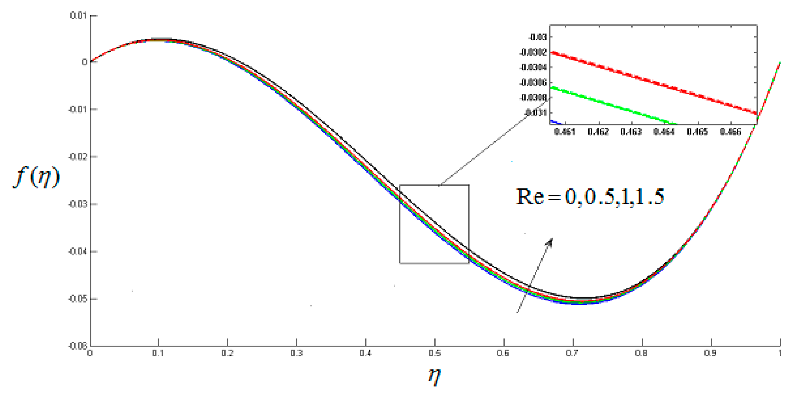
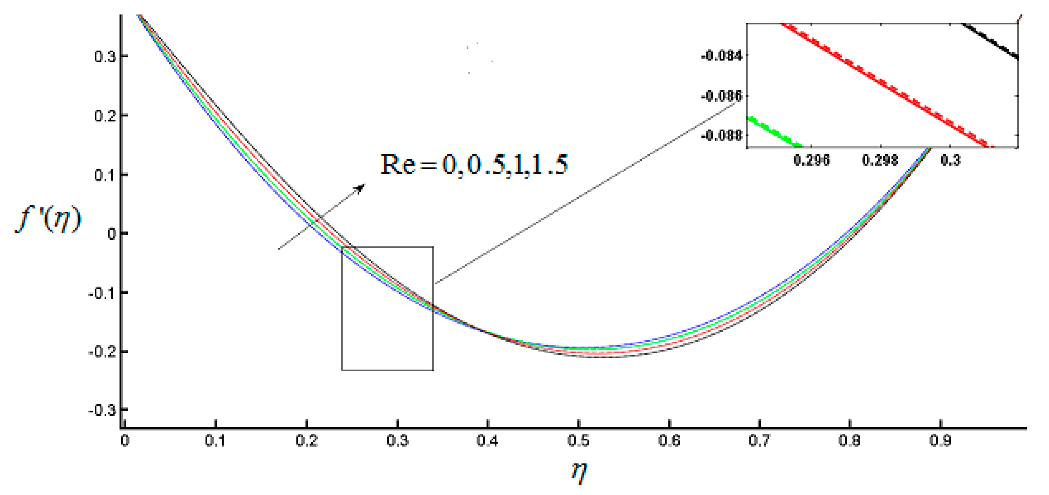
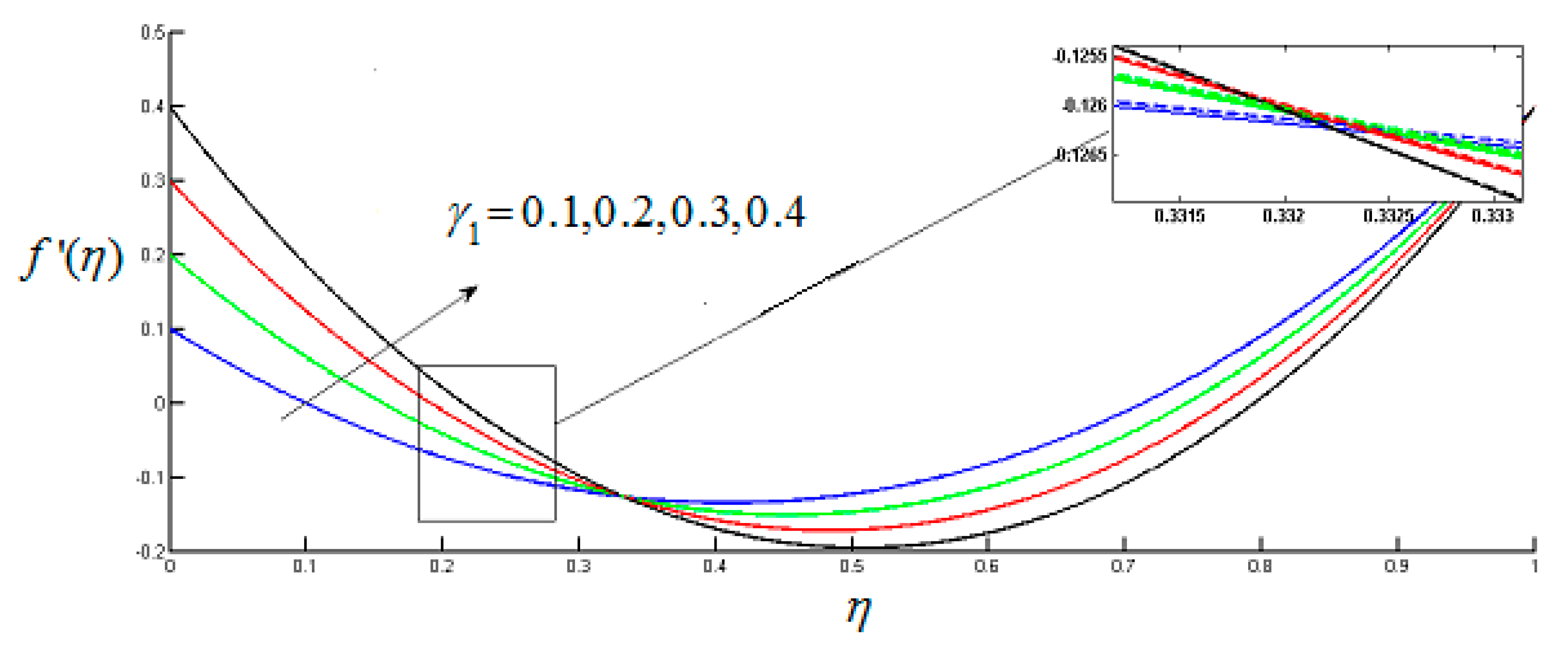
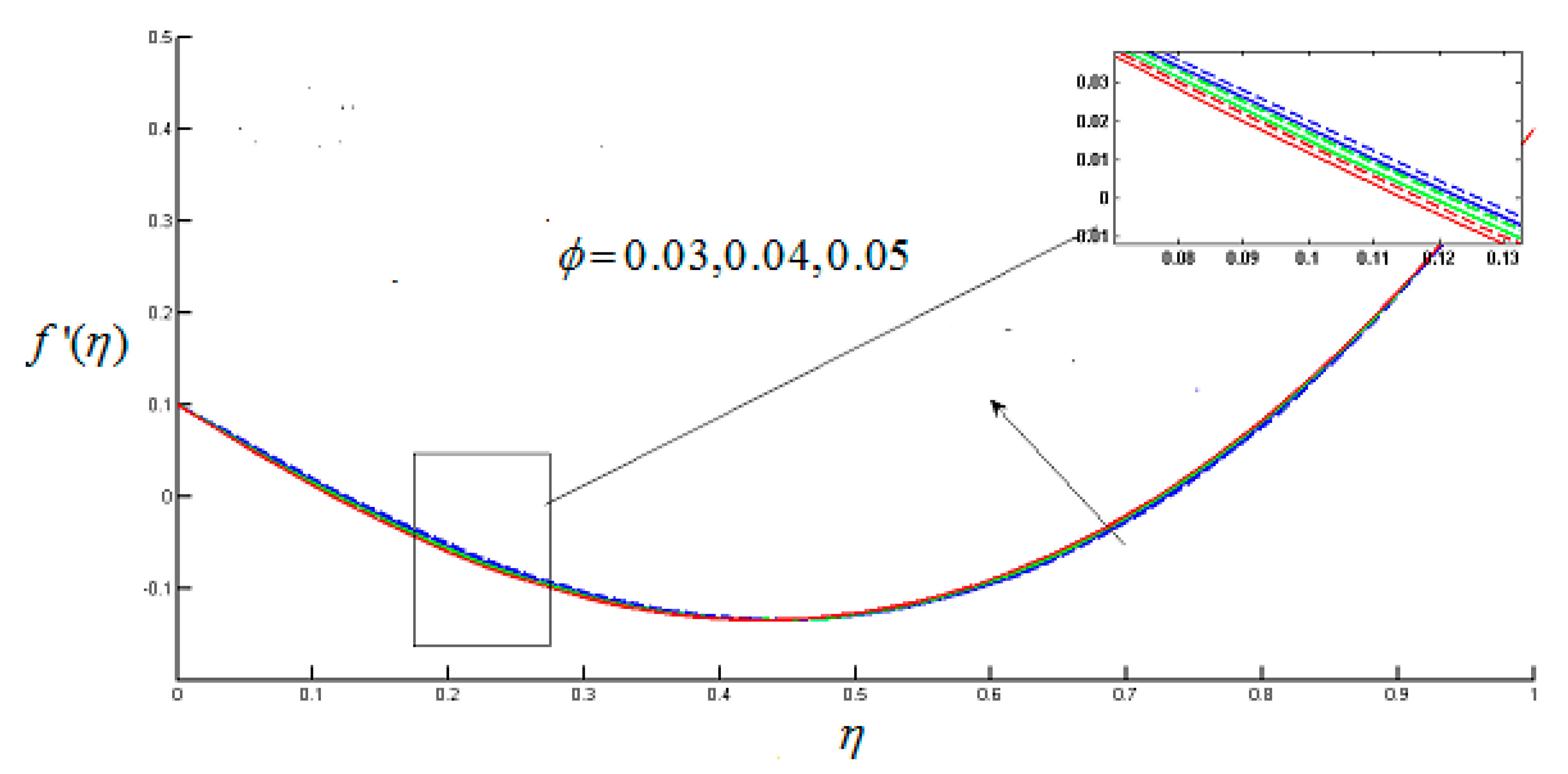
5.1. Radial and Axial Velocity Profile

In Figure 2, Figure 3, Figure 4, Figure 5, Figure 6, Figure 7, Figure 8 and Figure 9, the radial velocity f ( η ) and axial velocity profiles f ( η ) is depicted for R e , parameters, scaled Stretching γ 1 and γ 2 and nanoparticle volume fraction ϕ . The solid line ( ) and the dashed line (----) represent the single wall carbon nanotubes and multiwall carbon nanotubes respectively. Figure 2 and Figure 3 show that the magnitude of radial f ( η ) and axial velocity f ( η ) reduces for incremental value of R e . The fact is that for increasing values of Reynolds number causes the increase in resistive forces which reduces the motion of fluid. Magnitude of f ( η )   and   f ( η ) for multiwall carbon nanotubes is higher as compared with single wall carbon nanotubes. f ( η ) takes on negative values near the lower disks because upper disks are moving faster than the lower disks. Figure 4 depicts that f ( η ) escalates in the vicinity of the lower disk and declines in the vicinity of the upper disks by enhancing the value of γ 1 , while the behavior of f ( η ) remain same throughout the system as shown in Figure 5. But by the increase in the value of γ 2 , f ( η ) increases in the vicinity of the lower disks and decreases in the vicinity of the upper disks, (see Figure 6), and f ( η ) shows decrease in magnitude throughout the system, (see Figure 7). Figure 8 shows that f ( η ) reduces by the increase of nanoparticle volume fraction and magnitude of f ( η ) is smaller for MWCNTs. f ( η ) is decreasing near the lower disk and enhancing near the upper disks by increasing ϕ , while the amplitude of f ( η ) is higher for MWCNTs than SWCNTs. This effect is shown in Figure 9.

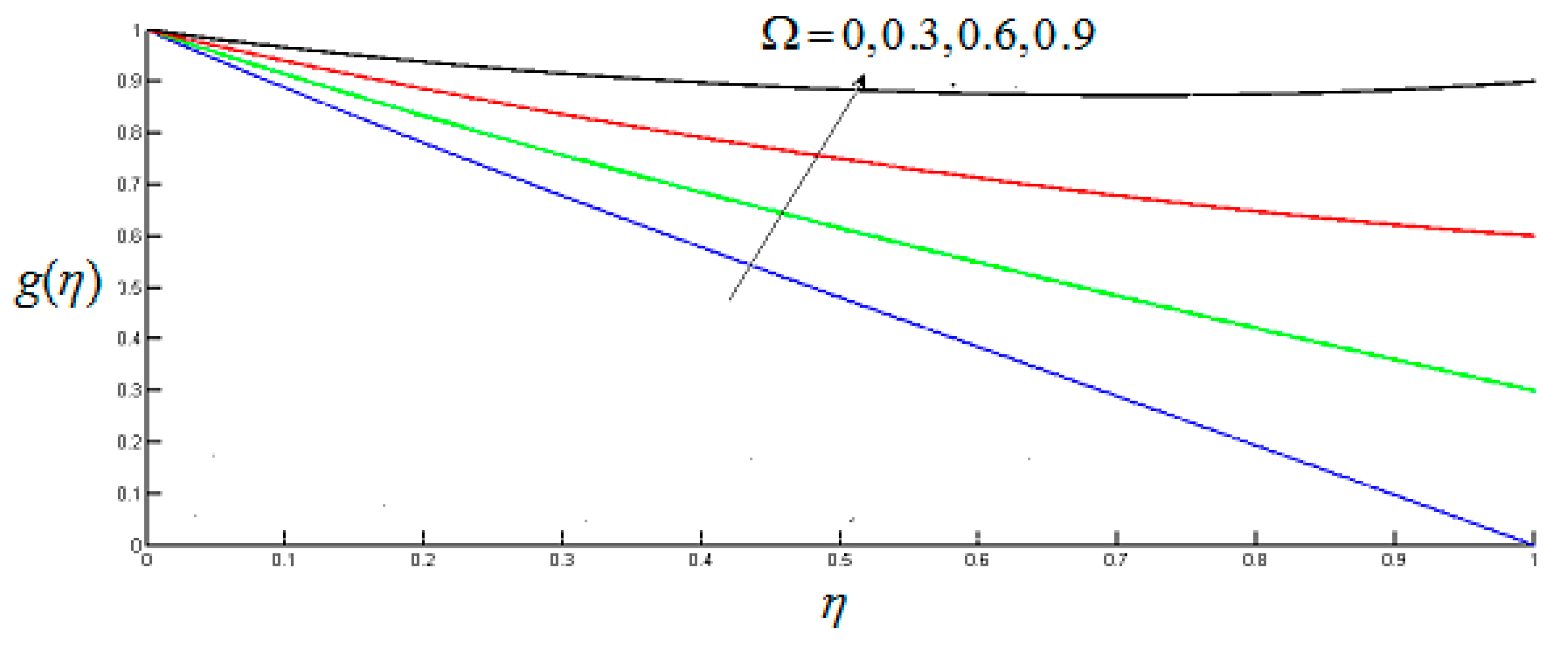
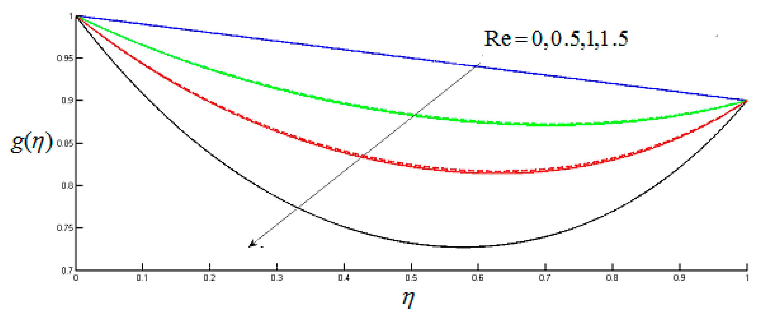
5.2. Tangential Velocity Profile

Tangential velocity g ( η ) decreases by escalating the value of M because increasing magnetic field exerts a retarding force which slows the motion of the particles within the fluid. Figure 10 depicts that the tangential velocity has smaller magnitude for MWCNTs as compared to SWCNTs. Figure 11 depicts that tangential velocity decreases for increasing value of A 1 and its value is smaller for MWCNTs. Figure 12 shows that as stretching rate increases at the upper disk it causes a decrease of tangential velocity. g ( η ) increases for incremental values of hall current parameter m and magnitude of tangential velocity profile is more increasing for MWCNTs as compared with SWCNTs as shown in Figure 13. Figure 14 depicts the relationship between Ω and g ( η ) . It represents that the tangential velocity is an escalating function of rotation parameter. Figure 15 and Figure 16 depict that for increasing ϕ the amplitude of g ( η ) increases and it decreases for increasing Reynolds number.

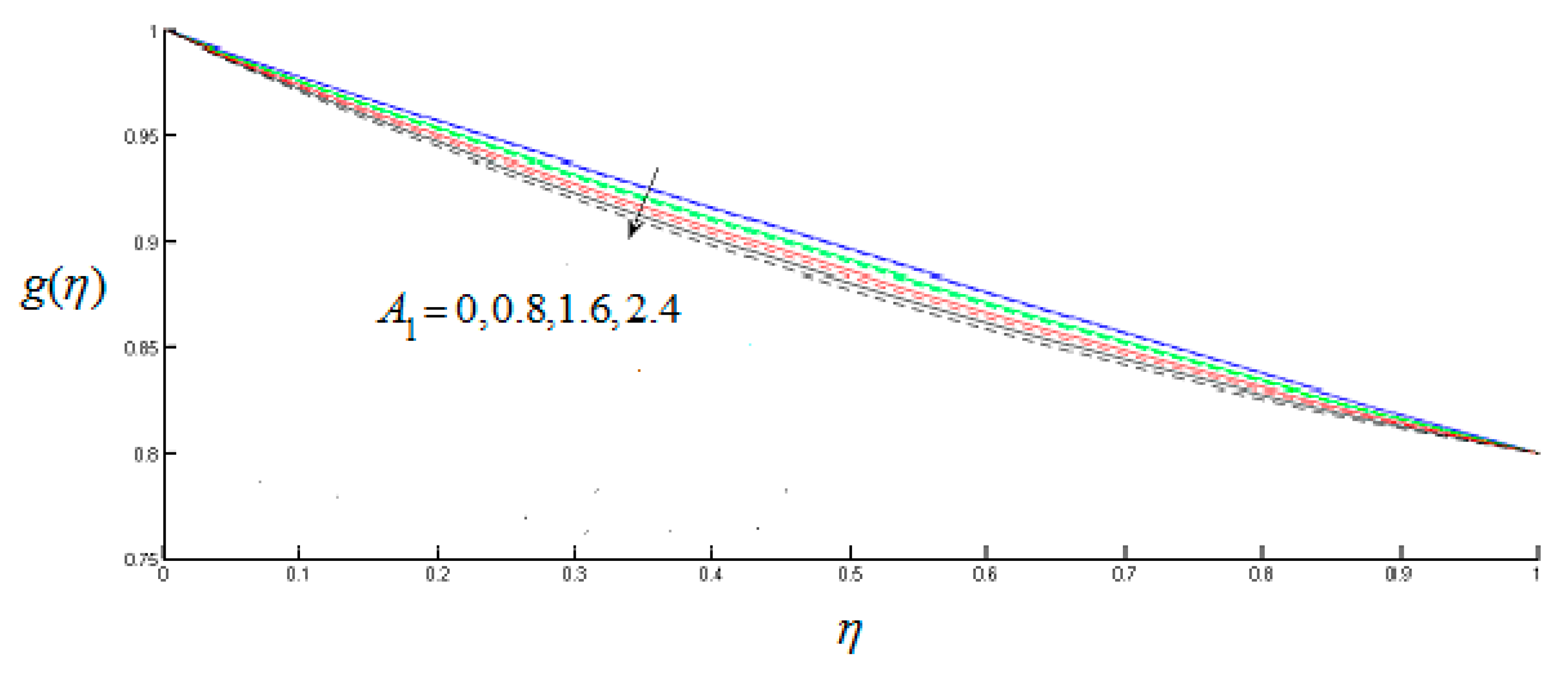
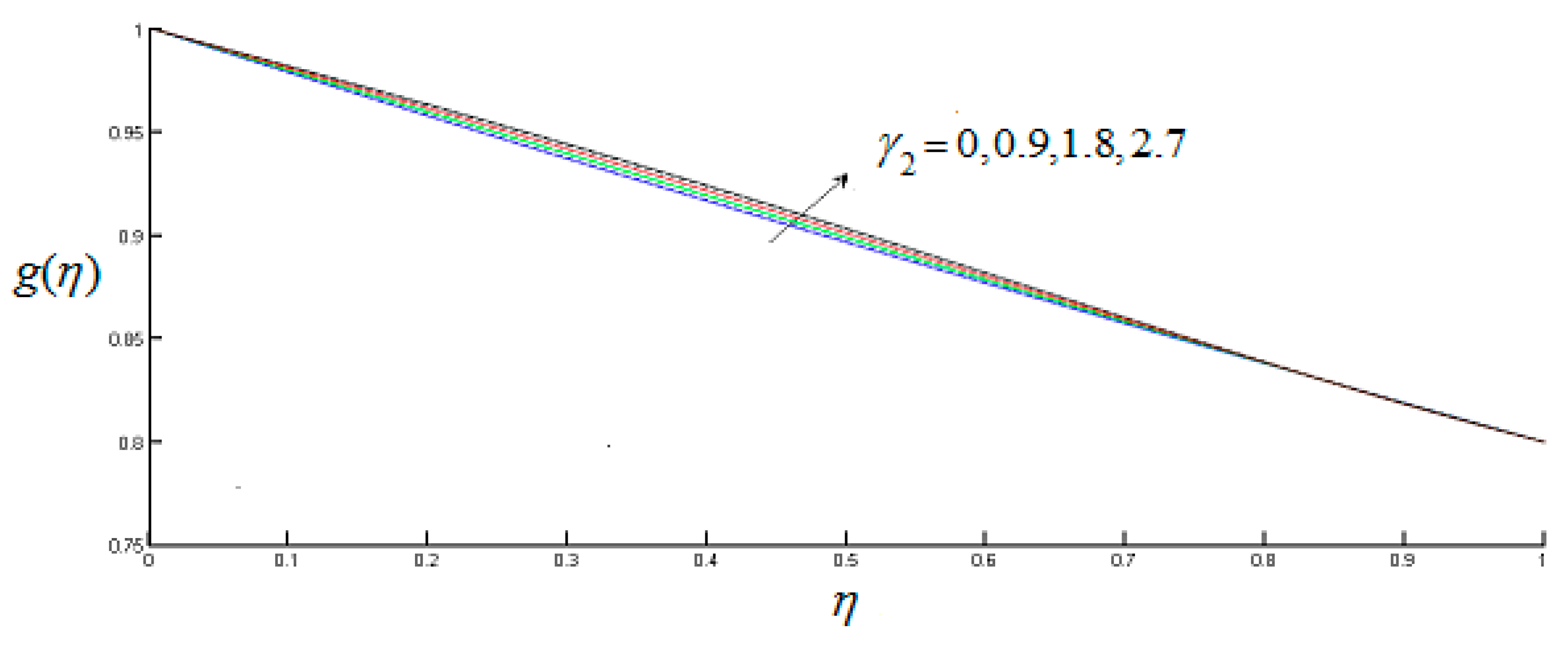
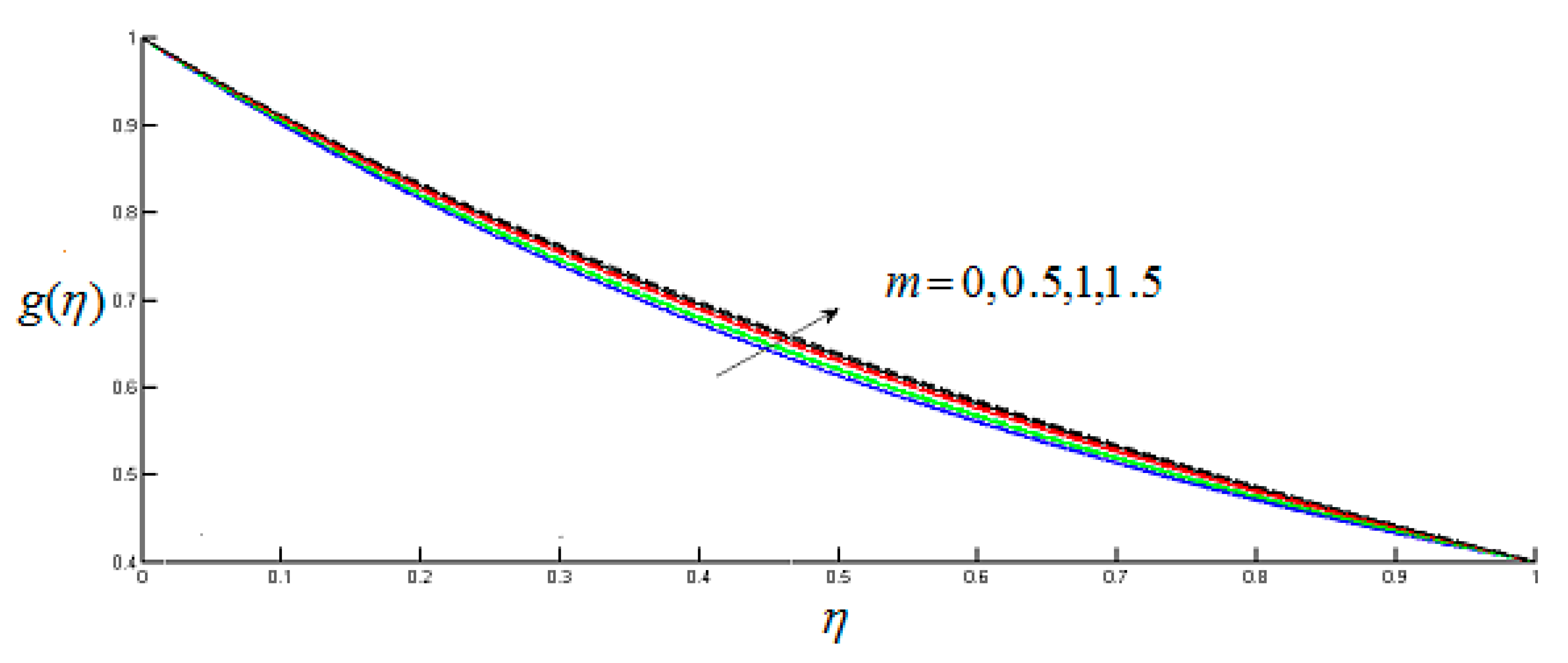
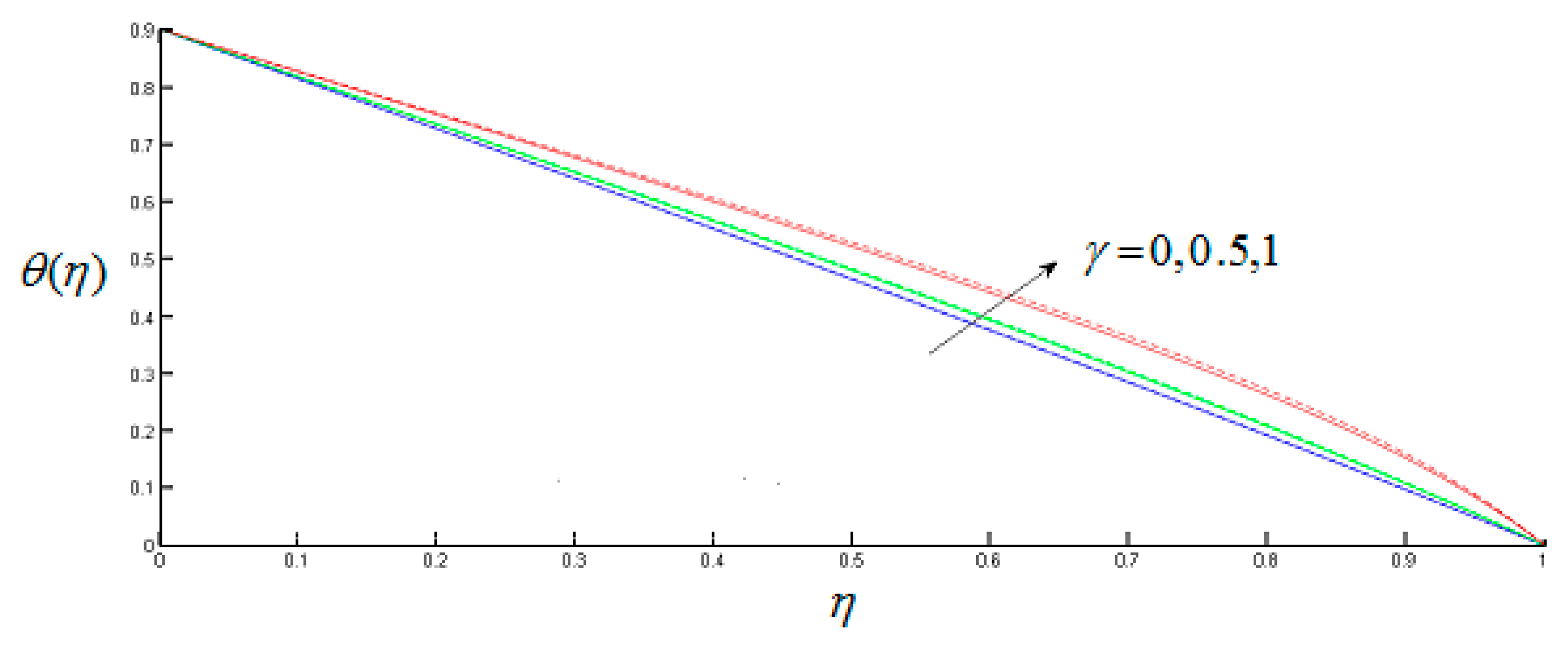
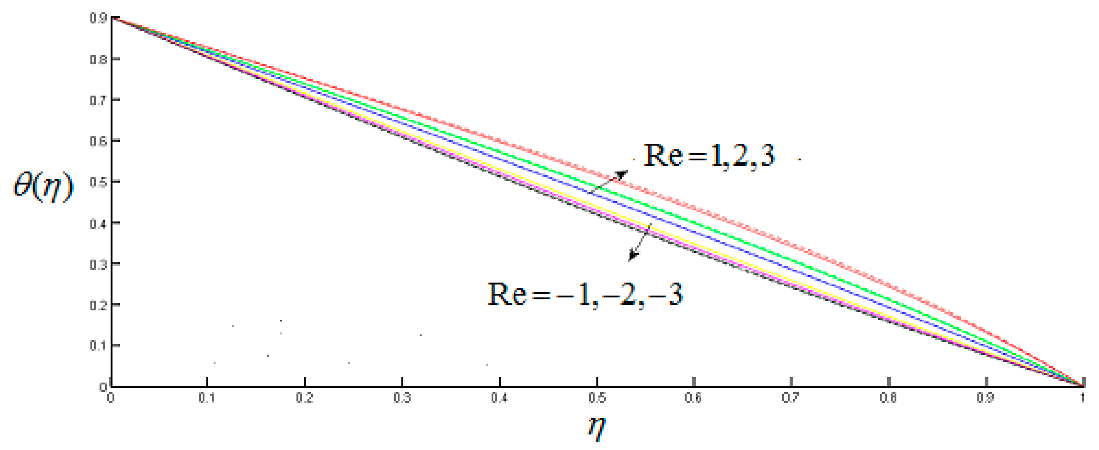
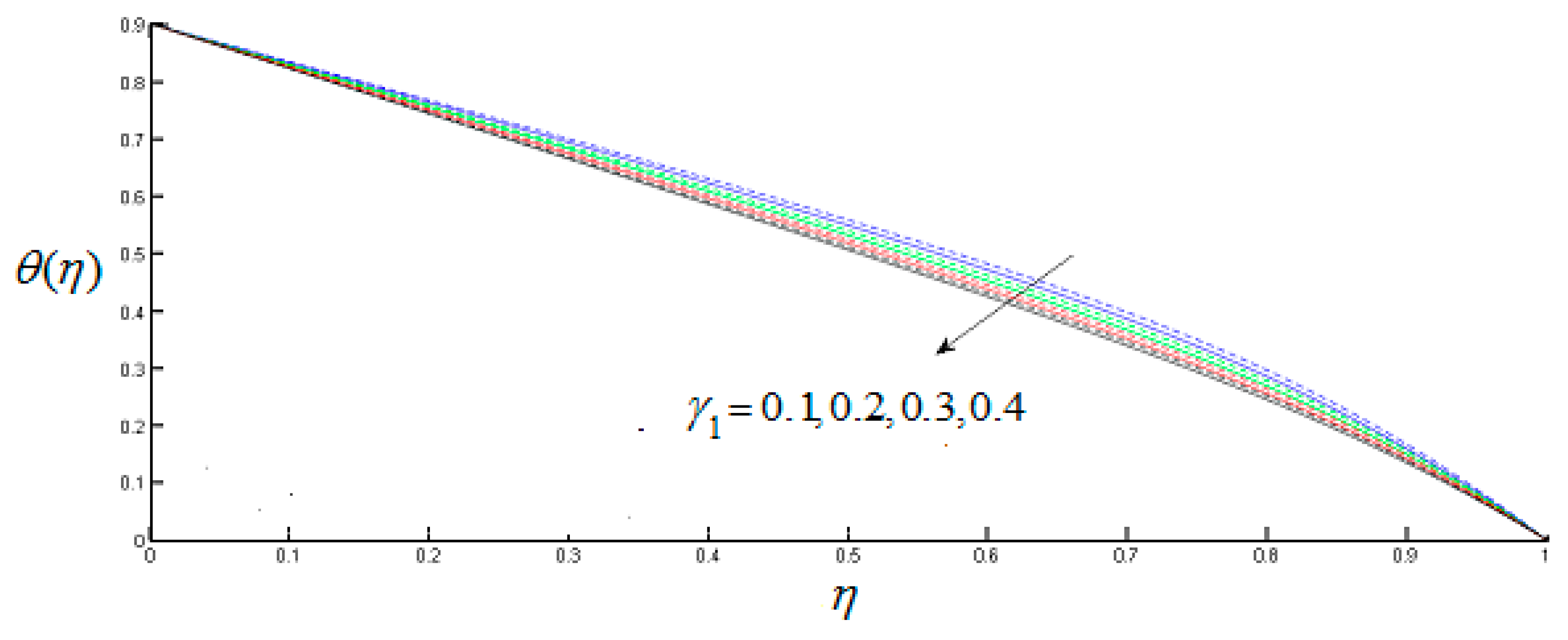
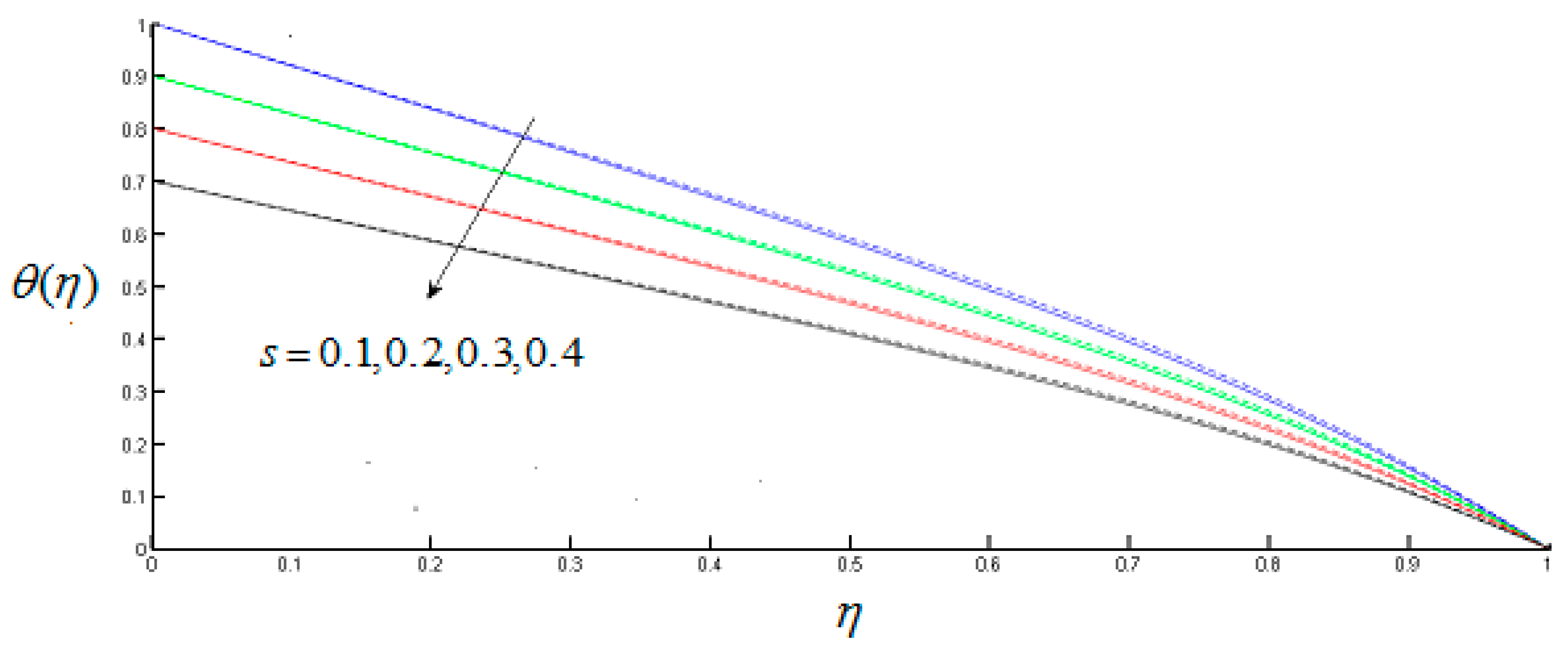
5.3. Dimensionless Temperature Distribution

The dimensionless temperature distribution for different values of relaxation parameter is depicted for both MWCNTs and SWCNTs in Figure 17. The figure shows that higher rate of thermal relaxation parameter causes the increase in temperature profile. Results shows that temperature profile is more increasing for MWCNTs than SWCNTs. Figure 18 shows that temperature decreases by increasing nanoparticle volume fraction and temperature profile shows more decreasing behavior for MWCNTS as compared to SWCNTs. Effect of Reynolds number, Prandtl number, stratification parameter, unsteadiness parameter A 1 , stretching parameter γ 1 at lower disk on temperature profile is shown in Figure 19, Figure 20, Figure 21, Figure 22 and Figure 23. Results are plotted both for MWCNTs and MWCNTs. Figure 19 shows that for positive values of R e there is an increase in temperature profile, and it shows that multi-walled carbon nanotubes have higher temperature distribution for increasing Reynolds number as compared to single-walled carbon nanotubes. Similarly, graph is plotted for negative values of Reynolds number. It is revealed that on decreasing the value of Reynolds number, temperature profile also decreases and shows more decreasing behavior for MWCNTs than SWCNTs. Figure 20, Figure 21 and Figure 22 portray the variation of temperature profile which decreases for incremental values of s , A 1 , and γ 1 this decreasing behavior is observed more for SWCNTs as compared with MWCNTs. Figure 23 depicts for increasing value of Prandtl number temperature profile decreases. The decrease in temperature by augmentation of Prandtl number is consistent with the physical expectation, as by increasing Prandtl number fluid possesses lower thermal diffusivity which causes the thickness of thermal boundary layer to decrease.

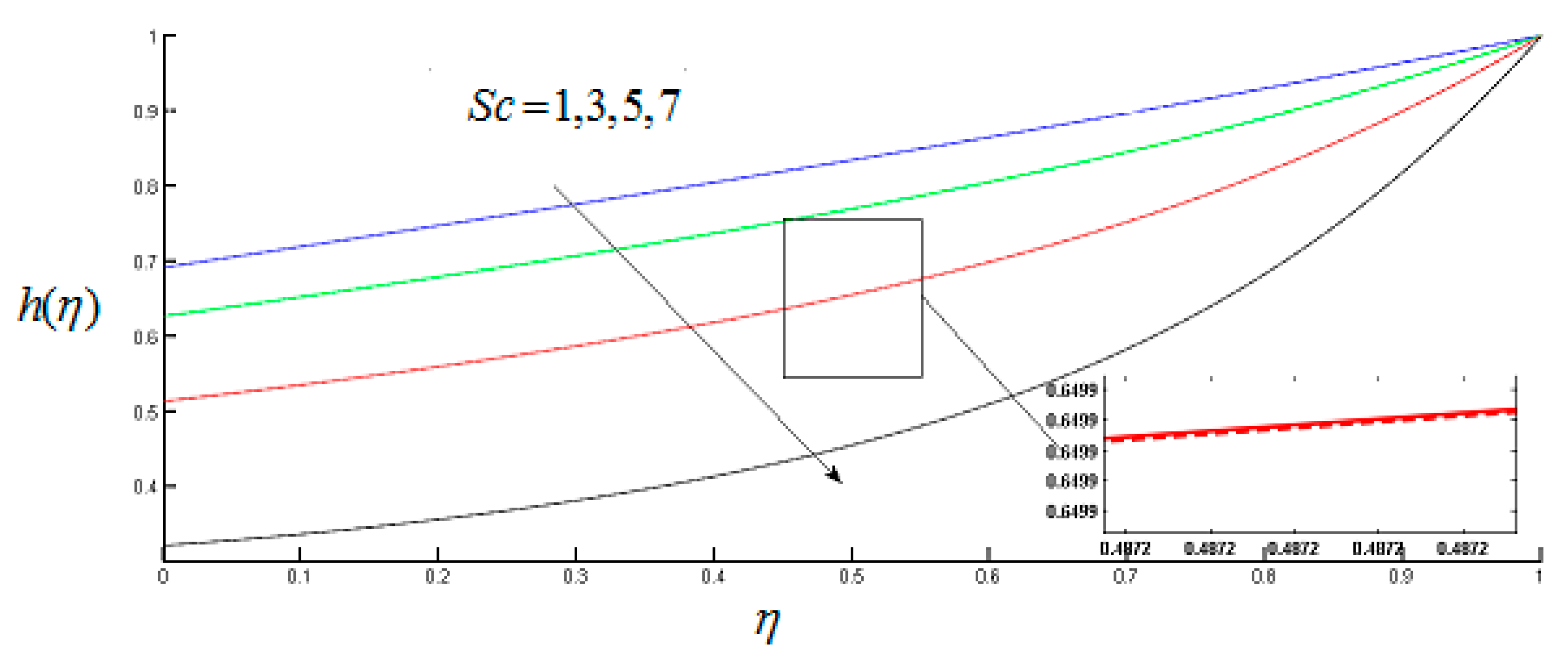
5.4. Concentration Profile

Figure 24 demonstrate the analysis of concentration profile. For various estimates of homogeneous reaction parameter k 1 there is decay in concentration profile. Similar results are obtained for heterogeneous reaction parameter k 2 in Figure 25. Concentration field is observed for Schmidt number in Figure 26. As it is momentum to mass diffusivity ratio, so smaller the value of mass diffusivity, stronger the value of Schmidt number, which causes the reduction of the concentration of the fluid.
Comparison of f ( 0 ) and g ( 0 ) with Stewartson [42] for several estimates of Ω by considering all extra terms as zero is depicted in Table 3. An excellent synchronization is achieved in this case. This substantiates our mathematical model and presented results.

5.5. Drag Force Coefficient and Heat Transfer Rate

Influence of Hartmann number M , Hall current parameter m, stretching parameter γ 1 and γ 2 , and Reynolds number on Skin friction coefficients for MWCNTs and SWCNTs at both disks is portrayed in Table 4. Skin coefficient friction decrease by increasing the value of Hall current parameter m and Hartmann number M at lower and upper disk for both MWCNTs and SWCNTs, while increasing behavior for R e and scaled stretching parameter γ 1 for disk at z = 0 and stretching parameter γ 2 for the disk at z = h ( t ) for both MWCNTs and SWCNTs.
Table 5 is erected to depict the impact of numerous parameters on heat transfer rate. It is gathered that rate of heat transfer is a decreasing function of unsteadiness parameter and Prandtl number at lower disk for both MWCNTS and SWCNTs, while it is a decreasing function of Reynolds number at lower disk and increasing function of Reynolds number at upper disk for both MWCNTs and SWCNTs.

6. Conclusions

Unsteady axisymmetric MHD flow and transfer of heat with water-based carbon nanotubes amid two stretchable rotating disks is explored in the present study. Results for arising parameters for both SWCNTs and MWCNTs are illustrated. Main findings of our observations are as follows.
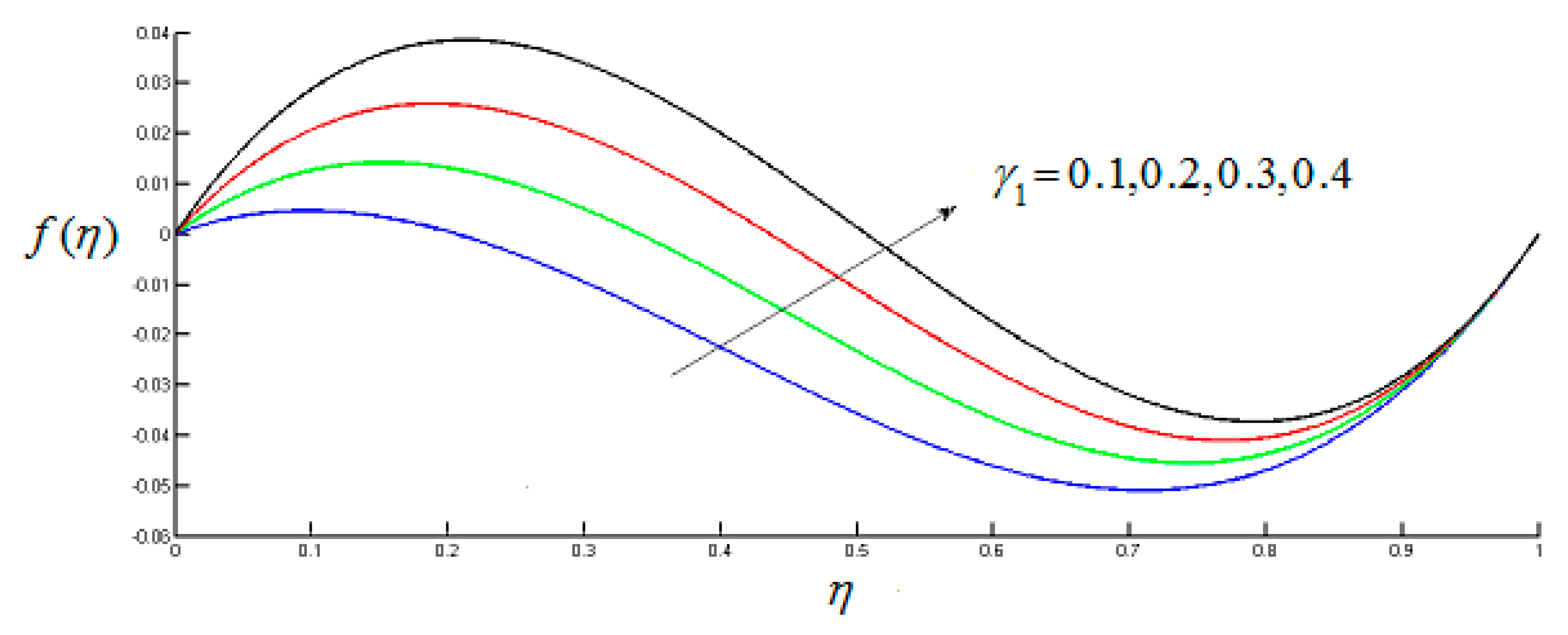
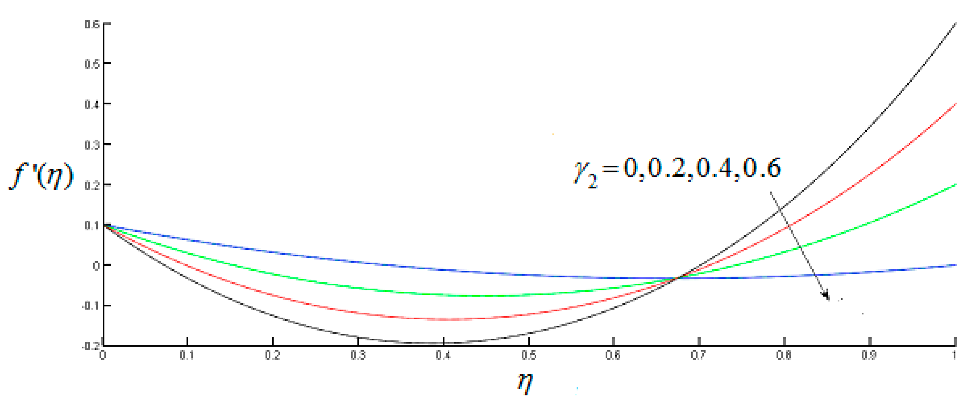
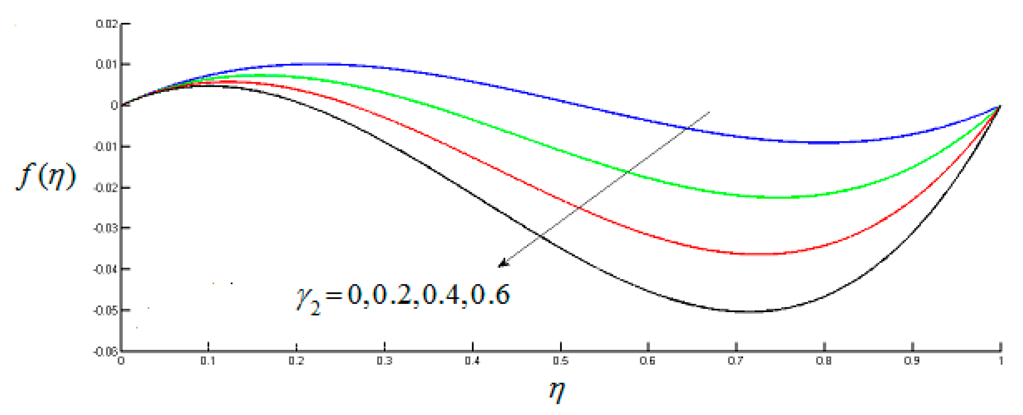
  • Radial velocity increases and declines in the vicinity of the lower and the upper disks respectively.
  • Radial and axial velocity profile is increasing for stretching parameter γ 1 and decreasing behavior γ 2 near the lower disks for both types of walls.
  • Tangential velocity increases with increasing Hall current parameter and decreases with increasing Hartmann number in case of SWCNTs and MWCNTs.
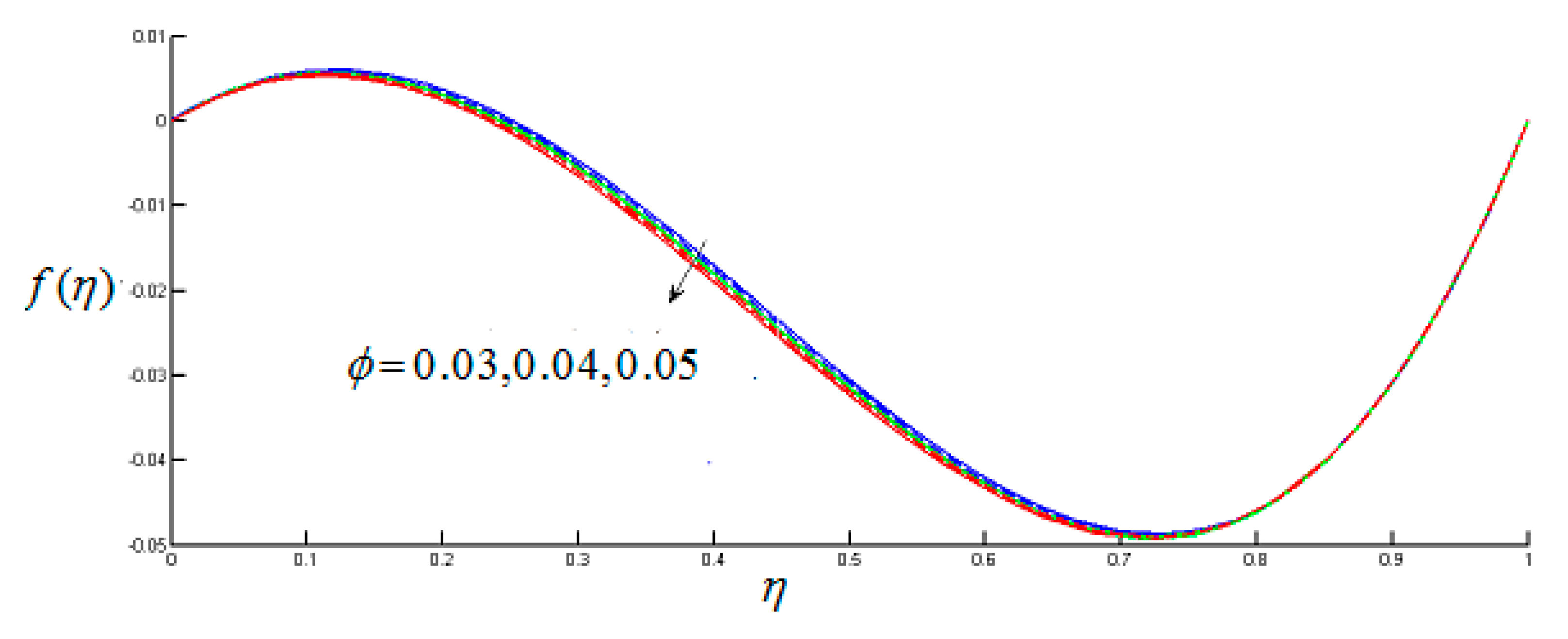
  • Temperature increases for thermal relaxation parameter, and decreases for nanoparticle volume fraction.
  • In H-H reactions the concentration profile decreases for both types of CNTs.
  • For incremental value of thermal stratification parameters temperature profile decreases.

Author Contributions

Conceptualization, M.R.; Methodology, S.R.; software, S.K.; Validation, P.K. and Y.N.; Formal Analysis, S.R.; Investigation, F.H.; X.X.; Writing—Original Draft Preparation, S.R.; Writing—Review and Editing, M.R.; visualization, S.K.; Supervision, M.R.; Project Administration, M.R.; Funding Acquisition, P.K. and Y.N.; All authors have read and agreed to the published version of the manuscript.

Funding

This research was funded by the Bio & Medical Technology Development Program of the NRF funded by the Korean government, MSIP(NRF-2015M3A9D7067219) and also supported by the Soonchunhyang University Research Fund.

Conflicts of Interest

Authors have no conflict of interest regarding this publication.

Nomenclature

SymbolsDescription
V = V ( u , v , w ) Velocity of the fluid ( m / s )
M Hartmann number
T Temperature ( K )
T 0 Reference temperature ( K )
A , B The dimensional constant K . m 1
γ 1 Scale stretching parameters at lower disk
γ 2 Scale stretching parameters at upper disk
Ω 1 Angular velocity of the lower disk ( sec 1 )
Ω 2 Angular velocity of the upper disk ( sec 1 )
C p Specific heat ( J k g k )
A 1 Unsteadiness parameter
ε 1 Thermal relaxation time ( sec )
B 0 Applied magnetic field ( Tesla )
σ n f Thermal conductivity of nanofluid ( S / m )
σ f Thermal conductivity of the fluid ( S / m )
k 1 Measure of strength of homogeneous reaction
Ω Rotation parameter
S c Schmidt number
D A Diffusion coefficient of chemical species A * ( c m 2 / s )
s Thermal stratification parameter
k 2 Measure of strength of heterogeneous reaction
Re Reynolds number
μ f Dynamic viscosity of fluid ( P a . s )
μ n f Dynamic viscosity of nanofluid ( P a . s )
ρ f Density of the fluid ( k g m 3 )
k n f Thermal conductivity of the nanofluid ( W / m k )
ρ n f Density of the nanofluid ( k g m 3 )
k C N T Thermal conductivity of carbon nanotubes ( W / m k )
k f Thermal conductivity of the fluid ( W / m k )
δ Ratio of diffusion coefficients
D B Diffusion coefficient of chemical species B * ( c m 2 / s )
Pr Prandtl number
ε Pressure parameter

References

  1. Suleman, M.; Ramzan, M.; Ahmad, S.; Lu, D.; Muhammad, T.; Chung, J.D. A Numerical Simulation of Silver–Water Nanofluid Flow with Impacts of Newtonian Heating and Homogeneous–Heterogeneous Reactions Past a Nonlinear Stretched Cylinder. Symmetry 2019, 11, 295. [Google Scholar] [CrossRef] [Green Version]
  2. Wang, X.Q.; Mujumdar, A.S. Heat transfer characteristics of nanofluids: A review. Int. J. Therm. Sci. 2007, 46, 1–19. [Google Scholar] [CrossRef]
  3. Alawi, O.A.; Sidik, N.A.C.; Xian, H.W.; Kean, T.H.; Kazi, S.N. Thermal conductivity and viscosity models of metallic oxides nanofluids. Int. J. Heat Mass Transf. 2018, 116, 1314–1325. [Google Scholar] [CrossRef]
  4. Choi, S.U.; Eastman, J.A. Enhancing Thermal Conductivity of Fluids with Nanoparticles; (No. ANL/MSD/CP-84938; CONF-951135-29); Argonne National Lab.: Lemont, IL, USA, 1995. [Google Scholar]
  5. Ali, N.; Teixeira, J.A.; Addali, A. A review on nanofluids: Fabrication, stability, and thermophysical properties. J. Nanomater. 2018. [Google Scholar] [CrossRef]
  6. Sheikholeslami, M.; Ellahi, R.; Vafai, K. Study of Fe3O4-water nanofluid with convective heat transfer in the presence of magnetic source. Alex. Eng. J. 2018, 57, 565–575. [Google Scholar] [CrossRef]
  7. Haq, R.U.; Noor, N.F.M.; Khan, Z.H. Numerical simulation of water based magnetite nanoparticles between two parallel disks. Adv. Powder Technol. 2016, 27, 1568–1575. [Google Scholar] [CrossRef]
  8. Khan, Z.H.; Hussain, S.T.; Hammouch, Z. Flow and heat transfer analysis of water and ethylene glycol based Cu nanoparticles between two parallel disks with suction/injection effects. J. Mol. Liq. 2016, 221, 298–304. [Google Scholar]
  9. Saidi, M.H.; Tamim, H. Heat transfer and pressure drop characteristics of nanofluid in unsteady squeezing flow between rotating porous disks considering the effects of thermophoresis and Brownian motion. Adv. Powder Technol. 2016, 27, 564–574. [Google Scholar] [CrossRef]
  10. Hayat, T.; Javed, M.; Imtiaz, M.; Alsaedi, A. Convective flow of Jeffrey nanofluid due to two stretchable rotating disks. J. Mol. Liq. 2017, 240, 291–302. [Google Scholar] [CrossRef]
  11. Pourmehran, O.; Sarafraz, M.M.; Rahimi-Gorji, M.; Ganji, D.D. Rheological behaviour of various metal-based nano-fluids between rotating discs: A new insight. J. Taiwan Inst. Chem. Eng. 2018, 88, 37–48. [Google Scholar] [CrossRef]
  12. Herlem, G.; Picaud, F.; Girardet, C.; Micheau, O. Carbon Nanotubes: Synthesis, Characterization, and Applications in Drug-Delivery Systems. In Nanocarriers for Drug Delivery; Elsevier: Amsterdam, The Netherlands, 2019; pp. 469–529. [Google Scholar]
  13. Ong, Y.T.; Ahmad, A.L.; Zein, S.H.S.; Tan, S.H. A review on carbon nanotubes in an environmental protection and green engineering perspective. Braz. J. Chem. Eng. 2010, 27, 227–242. [Google Scholar] [CrossRef]
  14. Simon, J.; Flahaut, E.; Golzio, M. Overview of Carbon Nanotubes for Biomedical Applications. Materials 2019, 12, 624. [Google Scholar] [CrossRef] [Green Version]
  15. Imtiaz, M.; Hayat, T.; Alsaedi, A.; Ahmad, B. Convective flow of carbon nanotubes between rotating stretchable disks with thermal radiation effects. Int. J. Heat Mass Transf. 2016, 101, 948–957. [Google Scholar] [CrossRef]
  16. Haq, R.U.; Hammouch, Z.; Khan, W.A. Water-based squeezing flow in the presence of carbon nanotubes between two parallel disks. Therm. Sci. 2016, 20. [Google Scholar] [CrossRef]
  17. Mosayebidorcheh, S.; Hatami, M. Heat transfer analysis in carbon nanotube-water between rotating disks under thermal radiation conditions. J. Mol. Liq. 2017, 240, 258–267. [Google Scholar] [CrossRef]
  18. Jyothi, K.; Reddy, P.S.; Reddy, M.S. Influence of magnetic field and thermal radiation on convective flow of SWCNTs-water and MWCNTs-water nanofluid between rotating stretchable disks with convective boundary conditions. Powder Technol. 2018, 331, 326–337. [Google Scholar] [CrossRef]
  19. Kaempgen, M.; Duesberg, G.S.; Roth, S. Transparent carbon nanotube coatings. Appl. Surf. Sci. 2005, 252, 425–429. [Google Scholar] [CrossRef]
  20. Keefer, E.W.; Botterman, B.R.; Romero, M.I.; Rossi, A.F.; Gross, G.W. Carbon nanotube coating improves neuronal recordings. Nat. Nanotechnol. 2008, 3, 434. [Google Scholar] [CrossRef]
  21. Besteman, K.; Lee, J.O.; Wiertz, F.G.; Heering, H.A.; Dekker, C. Enzyme-coated carbon nanotubes as single-molecule biosensors. Nano Lett. 2003, 3, 727–730. [Google Scholar] [CrossRef]
  22. Lu, D.; Ramzan, M.; Mohammad, M.; Howari, F.; Chung, J.D. A Thin Film Flow of Nanofluid Comprising Carbon Nanotubes Influenced by Cattaneo-Christov Heat Flux and Entropy Generation. Coatings 2019, 9, 296. [Google Scholar] [CrossRef] [Green Version]
  23. Ramzan, M.; Gul, H.; Kadry, S. Onset of Cattaneo-Christov Heat Flux and Thermal Stratification in Ethylene-Glycol Based Nanofluid Flow Containing Carbon Nanotubes in a Rotating Frame. IEEE Access 2019, 7, 146190–146197. [Google Scholar] [CrossRef]
  24. Khan, U.; Ahmad, S.; Ramzan, M.; Suleman, M.; Lu, D.; Inam, S. Numerical Simulation of Darcy–Forchheimer 3D Unsteady Nanofluid Flow Comprising Carbon Nanotubes with Cattaneo–Christov Heat Flux and Velocity and Thermal Slip Conditions. Processes 2019, 7, 687. [Google Scholar] [CrossRef] [Green Version]
  25. Ramzan, M.; Mohammad, M.; Howari, F. Magnetized suspended carbon Nanotubes based nanofluid flow with bio-convection and entropy generation past a vertical cone. Sci. Rep. 2019, 9, 1–15. [Google Scholar] [CrossRef]
  26. Bilal, M.; Ramzan, M. Hall current effect on unsteady rotational flow of carbon nanotubes with dust particles and nonlinear thermal radiation in Darcy–Forchheimer porous media. J. Therm. Anal. Calorim. 2019, 138, 3127–3137. [Google Scholar] [CrossRef]
  27. Ramzan, M.; Shaheen, N. Thermally stratified Darcy–Forchheimer nanofluid flow comprising carbon nanotubes with effects of Cattaneo–Christov heat flux and homogeneous–heterogeneous reactions. Phy. Scr. 2019, 95, 015701. [Google Scholar] [CrossRef]
  28. Ramzan, M.; Mohammad, M.; Howari, F.; Chung, J.D. Entropy analysis of carbon nanotubes based nanofluid flow past a vertical cone with thermal radiation. Entropy 2019, 21, 642. [Google Scholar] [CrossRef] [Green Version]
  29. Hayat, T.; Haider, F.; Muhammad, T.; Ahmad, B. Darcy–Forchheimer flow of carbon nanotubes due to a convectively heated rotating disk with homogeneous–heterogeneous reactions. J. Therm. Anal. Calorimetry 2019, 137, 1939–1949. [Google Scholar] [CrossRef]
  30. Ramzan, M.; Sheikholeslami, M.; Chung, J.D.; Shafee, A. Melting heat transfer and entropy optimization owing to carbon nanotubes suspended Casson nanoliquid flow past a swirling cylinder-A numerical treatment. AIP Adv. 2018, 8, 115130. [Google Scholar] [CrossRef] [Green Version]
  31. Mahian, O.; Kianifar, A.; Kalogirou, S.A.; Pop, I.; Wongwises, S. A review of the applications of nanofluids in solar energy. Int. J. Heat Mass Transf. 2013, 57, 582–594. [Google Scholar] [CrossRef]
  32. Cattaneo, C. Sulla Conduzione del Calore; Atti Sem. Mat. Fis. Univ: Modena, Italy, 1948; Volume 3, pp. 83–101. [Google Scholar]
  33. Christov, C.I. On frame indifferent formulation of the Maxwell–Cattaneo model of finite-speed heat conduction. Mech. Res. Commun. 2009, 36, 481–486. [Google Scholar] [CrossRef]
  34. Hayat, T.; Qayyum, S.; Imtiaz, M.; Alsaedi, A. Flow between two stretchable rotating disks with Cattaneo-Christov heat flux model. Results Phys. 2017, 7, 126–133. [Google Scholar] [CrossRef]
  35. Dogonchi, A.S.; Chamkha, A.J.; Seyyedi, S.M.; Ganji, D.D. Radiative nanofluid flow and heat transfer between parallel disks with penetrable and stretchable walls considering Cattaneo–Christov heat flux model. Heat Transf. Asian Res. 2018, 47, 735–753. [Google Scholar] [CrossRef]
  36. Lu, D.; Li, Z.; Ramzan, M.; Shafee, A.; Chung, J.D. Unsteady squeezing carbon nanotubes based nano-liquid flow with Cattaneo–Christov heat flux and homogeneous–heterogeneous reactions. Appl. Nanosci. 2019, 9, 169–178. [Google Scholar] [CrossRef]
  37. Ramzan, M.; Liaquet, A.; Kadry, S.; Yu, S.; Nam, Y.; Lu, D. Impact of Second-Order Slip and Double Stratification Coatings on 3D MHD Williamson Nanofluid Flow with Cattaneo–Christov Heat Flux. Coatings 2019, 9, 849. [Google Scholar] [CrossRef] [Green Version]
  38. Ramzan, M.; Gul, H.; Sheikholeslami, M. Effect of second order slip condition on the flow of tangent hyperbolic fluid—A novel perception of Cattaneo–Christov heat flux. Phys. Scr. 2019, 94, 115707. [Google Scholar] [CrossRef]
  39. Alebraheem, J.; Ramzan, M. Flow of nanofluid with Cattaneo–Christov heat flux model. Appl. Nanosci. 2019, 1–11. [Google Scholar] [CrossRef]
  40. Lu, D.; Ramzan, M.; Ahmad, S.; Chung, J.D.; Farooq, U. Upshot of binary chemical reaction and activation energy on carbon nanotubes with Cattaneo-Christov heat flux and buoyancy effects. Phys. Fluids 2017, 29, 123103. [Google Scholar] [CrossRef]
  41. Chaudhary, M.A.; Merkin, J.H. A simple isothermal model for homogeneous-heterogeneous reactions in boundary-layer flow. II Different diffusivities for reactant and autocatalyst. Fluid Dyn. Res. 1995, 16, 335. [Google Scholar] [CrossRef]
  42. Stewartson, K. On the flow between two rotating coaxial disks. In Mathematical Proceedings of the Cambridge Philosophical Society; Cambridge University Press: Cambridge, UK, 1953; Volume 49, pp. 333–341. [Google Scholar]
Figure 1. Schematic picture of the fluid flow.
Coatings 10 00048 g001
Figure 2. Axial velocity profile f ( η ) for R e .
Coatings 10 00048 g002
Figure 3. Radial velocity profile f ( η ) for R e .
Coatings 10 00048 g003
Figure 4. Radial velocity profile f ( η ) for γ 1 .
Coatings 10 00048 g004
Figure 5. Axial velocity profile f ( η ) for γ 1 .
Coatings 10 00048 g005
Figure 6. Radial velocity profile f ( η ) for γ 2 .
Coatings 10 00048 g006
Figure 7. Axial velocity profile f ( η ) for γ 2 .
Coatings 10 00048 g007
Figure 8. Radial velocity profile f ( η ) for ϕ .
Coatings 10 00048 g008
Figure 9. Axial velocity profile f ( η ) for ϕ .
Coatings 10 00048 g009
Figure 10. Tangential velocity profile for M .
Coatings 10 00048 g010
Figure 11. Tangential velocity profile for A 1 .
Coatings 10 00048 g011
Figure 12. Tangential velocity profile for γ 2 .
Coatings 10 00048 g012
Figure 13. Tangential velocity profile for m.
Coatings 10 00048 g013
Figure 14. Tangential velocity profile for Ω .
Coatings 10 00048 g014
Figure 15. Tangential velocity profile for R e .
Coatings 10 00048 g015
Figure 16. Tangential velocity profile for ϕ .
Coatings 10 00048 g016
Figure 17. Temperature profile for γ .
Coatings 10 00048 g017
Figure 18. Temperature profile for ϕ .
Coatings 10 00048 g018
Figure 19. Temperature profile for R e .
Coatings 10 00048 g019
Figure 20. Temperature profile for γ 1 .
Coatings 10 00048 g020
Figure 21. Temperature profile for A 1 .
Coatings 10 00048 g021
Figure 22. Temperature profile for s .
Coatings 10 00048 g022
Figure 23. Temperature profile for P r .
Coatings 10 00048 g023
Figure 24. Concentration profile for k 1 .
Coatings 10 00048 g024
Figure 25. Concentration profile for S c .
Coatings 10 00048 g025
Figure 26. Concentration profile for k 2 .
Coatings 10 00048 g026
Table 1. A comparison table depicting uniqueness of presented mathematical model.
AuthorCC Heat FluxHH ReactionsNanofluid with CNTsHall EffectThermal StratificationRotating Parallel Disks
Hayat et al. [10]×××××
Imtiaz et al. [15]××××
Hayat et al. [34]×××
Lu et al. [36]××
Present
(×) shows effect is absent and (√) shows the presence of effect.
Table 2. Thermo-physical properties of water and carbon nanotubes.
Physical PropertiesBase Fluid (H2O)MWCNTsSWCNTs
C p ( J k g k ) 4179796425
ρ ( k g m 3 ) 997.116002600
k ( W m k ) 0.61330006600
Table 3. Comparison of f ( 0 ) and g ( 0 ) for numerous estimates of Ω with Stewartson [42].
Ω f ( 0 ) Present g ( 0 ) Present
1.0 0.06666 0.06665 2.00095 2.00096
0.8 0.08394 0.08394 1.80259 1.80259
0.3 0.10395 0.10396 1.30442 1.30443
0.0 0.09997 0.09998 1.00428 1.00429
0.5 0.06663 0.06664 0.50261 0.50262
Table 4. Numerical values of drag force coefficient at lower and upper disk for SWCNTs and MWCNTs when A 1 = 0.5 ,   Pr = 6.7 ,   Ω = 0.5 ,   S = 0.4 ,   k 1 = 0.1 ,   k 2 = 0.1 ,   m = 0.5 ,   S c = 1 .
m M R e γ 1 γ 2 SWCNTs
C 1
MWCNTs
C 1
SWCNTs
C 2
MWCNTs
C 2
005.034115.034576.042426.04063
0.55.025685.024666.041636.0397
15.017325.014866.040916.03888
0.505.034115.034576.042426.04063
0.55.028965.028526.040236.03805
15.023855.022536.038086.03553
0.50.50.54.135614.142615.583415.59479
14.24274.489045.9841816.19988
1.55.157026.334937.143818.20049
0.10.12.940982.943994.878094.86666
0.23.605493.608365.227875.21623
0.10.62.940982.943994.878094.86666
0.83.5535833.562236.329216.31152
Table 5. Numerical values of heat transfer rate at lower and upper disk for SWCNTs and MWCNTs when Ω = 0.5 ,   γ 1 = 0.1 ,   γ 2   = 0.4 ,   k 1 = 0.1 ,   k 2 = 0.1 ,   m = 0.5 ,   S c = 1 .
S P r R e A 1 SWCNTs
k n f k f θ ( 0 )
MWCNTs
k n f k f θ ( 0 )
SWCNTs
k n f k f θ ( 1 )
MWCNTs
k n f k f θ ( 1 )
0.24.141353.831314.496964.16193
0.43.105772.873243.371823.12053
0.62.017011.915162.246682.07914
0.71.55241.436131.684111.55844
0.23.94.128243.818064.519454.18466
5.24.121643.811394.5308614.19621
1.30.24.135033.824864.507944.17309
0.54.115943.818394.541544.18437
0.10.64.102893.795714.5930214.25082
0.74.057463.753674.7059414.35533
0.84.005093.70524.836594.47624

