Article

Mechanical and Structural Properties of Nanocomposite CrAlSiN–AlSiN Coating with Periodically Modulated Composition

1
Central Laboratory of Applied Physics, Bulgarian Academy of Sciences, 61 St. Petersburg Blvd., 4000 Plovdiv, Bulgaria
2
Institute of General and Inorganic Chemistry, Bulgarian Academy of Sciences, 1113 Sofia, Bulgaria
3
Department of Solid State Physics and Microelectronics, Faculty of Physics, Sofia University, 5, J. Baucher Blvd., 1164 Sofia, Bulgaria
*
Author to whom correspondence should be addressed.
Coatings 2020, 10(1), 41; https://doi.org/10.3390/coatings10010041
Submission received: 5 December 2019 / Revised: 23 December 2019 / Accepted: 27 December 2019 / Published: 3 January 2020
(This article belongs to the Special Issue Coatings and Interfaces)

Abstract

:
A nanocomposite CrAlSiN–AlSiN coating with periodically modulated composition was developed and investigated regarding the effect of the composition and structure on the mechanical properties. The modulation was performed by variation of the pressure, cathode current and bias voltage during deposition. The structure and composition of the coating were investigated by X-ray diffraction (XRD), energy-dispersive X-ray spectroscopy (EDS), and X-ray photoelectron spectroscopy (XPS) analyses. The coating had a nanocomposite structure consisting of (CrAl)N and (AlSi)N nanograins embedded in a Si3N4 matrix. The EDS analysis of the cross-section revealed that the period composition had changed from Cr051Al0.41Si0.08N to Al0.82Cr0.04Si0.14N. It was shown that the elastic modulus could be adjusted by composition modulation. The coating hardness of 54 GPa was obtained by nanoindentation. The modulated CrAlSiN–AlSiN coating exhibited improved elastic strain to failure (H/E* = 0.11, H—nanohardness, E*—the effective elastic modulus), excellent resistance to plastic deformation (H3/E*2 = 0.72), and elastic recovery of 70%, which suggested improved toughness.

1. Introduction

Various types of coatings, such as multicomponent, gradient, multilayer, and nanocomposite, have been used for many years for improving surface properties of industrial tools [1,2,3,4]. Recently, coatings combining enhanced mechanical properties (high hardness), improved tribological parameters (high wear resistance, a low friction coefficient), high temperature stability, better wear, and oxidation resistance have been subjected to intensive research. A wide range of applications require coatings with high hardness (>40 GPa) and toughness [5,6,7,8,9,10]. However, superhard coatings exhibit lower plasticity, which results in lower toughness [11,12]. A. Leynad and A. Matthews proposed the concept of nanocomposite coatings with high hardness and low elastic modulus, which can exhibit improved toughness and therefore better wear resistance [13]. Two ratios, H/E (elastic strain to failure, E—elastic modulus) and H3/E2 (resistance to plastic deformation), have been used as ranking parameters correlating to the wear resistance of the coatings [13,14]. Thus, the development of superhard coatings with enhanced toughness should be directed toward the development of a suitable structure and composition, which could provide high elastic strain to failure, high resistance to plastic deformation, and high elastic recovery (We).
Among the large variety of coatings, CrN coatings demonstrated better wear resistance under severe tribological conditions due to its lower friction coefficient, and better corrosion and oxidation resistance [15,16]. Cr-based ternary and quaternary coatings have been developed in order to improve the mechanical and tribological properties demonstrated by CrN [17,18]. The quaternary CrAlSiN systems, having high hardness, excellent wear, and oxidation resistance, have attracted increasing attention since they promise to become multifunctional [8,9,18,19,20]. The modification of the CrN lattice, by addition of Si and Al atoms, causes enhanced hardness of the structure due to the solid solution hardening mechanism in CrAlSiN coatings [21,22]. These coatings exhibit very good resistance to plastic deformation (H3/E2 = 0.295 GPa [9]); but an optimal H/E ratio of 0.1 or higher, satisfyingly high elastic strain to failure, has not been achieved yet. Compared to CrAlSiN coatings, AlSiN coatings exhibit better elastic strain to failure, but lower hardness. They also demonstrate high resistance to plastic deformation, high temperature hardness, and high oxidation resistance [23,24,25]. Therefore, as layers in a multilayer structure, they might be beneficial for improving the elastic strain to failure of CrAlSiN nanocomposites and could contribute to good wear and oxidation resistance [26]. The multilayer structure with compositional modulation along the coating growth has been shown to be helpful in improving the properties of ternary and quaternary Cr-based coatings [27,28,29,30]. Moreover, several studies have proven that the interlayer with a median H/E ratio improves the wear resistance of the coating [30].
In this study, we propose a nanocomposite CrAlSiN–AlSiN coating with periodically modulated composition. The suggested structure targets improvement of the mechanical and tribological properties through hardness enhancement, increase in the elastic strain to failure, and resistance to plastic deformation. Two reference nanocomposites, CrAlSiN and AlSiN, were also developed. The results from the comparative study of the mechanical properties, structure, and composition of the modulated CrAlSiN–AlSiN coating and monolayer nanocomposites, CrAlSIN and AlSiN, are presented and discussed.

2. Experimental Details

2.1. Coating Preparation

The modulated CrAlSiN–AlSiN coating and reference nanocomposites, CrAlSiN and AlSiN, were deposited onto 5 mm-thick disks (coupons) of high-speed stainless steel (HSS) with a diameter of 10 mm for mechanical and tribological measurements; and on 10 mm × 10 mm square stainless steel DIN 1.4541 substrates (SS) for morphology, composition, and structure investigations. Preliminarily, the specimens were subjected to ultrasonically cleaning in an alkaline solution, followed by rinsing in de-ionized water and drying at 130 °C. The coatings were deposited by cathodic arc evaporation using a π80+ LARC® system (Platit, Grenchen, Switzerland) from two lateral rotating cathodes of Cr (99.99 wt.%) and AlSi alloy (82 at.% Al, 18 at.% Si). A three-axis planetary system was used to obtain uniform coating thickness [31]. Two cleaning treatments, using Ar discharge and Cr ions at a bias voltage of 1000 V, were performed prior to coating deposition. Coating deposition was performed in a nitrogen (99.9999%) atmosphere at a pressure in the range of 9 × 10⁻¹ to 4 Pa, depending on the required composition. The process started with deposition of a contact layer composed of Cr adhesion and CrN transition layers, followed by a CrAlSiN gradient layer. Next, the main structure of the coating was formed in three alternate periods with modulated composition. In each period, the composition was gradually modulated from Cr-rich to Al-rich regions (called CrAlSiN and AlSiN sublayers) by variation of the cathode current. The CrAlSiN sublayer was formed by changing the current of the Cr (ICr) and Al + Si (IAl+Si) cathodes from 125 to 120 A, and from 135 to 145 A, respectively. The bias voltage was maintained at −45 V. The AlSiN sublayer was deposited at an Al + Si cathode current of 160 A, and a bias voltage of −90 V. The transition between both sublayers was accomplished with a thin film, grown by gradually changing ICr from 120 A to zero, while IAl+Si increased to 160 A. The transition between the periods was also gradually formed by increasing ICr to 125 A, and decreasing IAl+Si to 135 A. The scheme illustrating the deposition process is presented in Figure 1.
The contact layer of the CrAlSiN and AlSiN nanocomposites was the same as that of the modulated coating. During deposition of the CrAlSiN nanocomposite film, the current of the Cr and Al + Si cathodes was 120 and 145 A, respectively. The bias voltage was −45 V. The AlSiN nanocomposite film was deposited at an Al + Si cathode current of 160 A, and a bias voltage of −90 V.
The modulated coating and reference nanocomposites were deposited at a constant temperature of 500 °C. After coating deposition, two-hour annealing at 525 °C in a nitrogen ambience was performed.

2.2. Characterization Methods

The mechanical properties were investigated using nanohardness measurements obtained using Compact Platform CPX (micro indentation tester/nanoindentation tester (MHT/NHT)) equipment (CSM Instruments, Anton Paar, Graz, Austria). Nanoindentation was performed with a certificated diamond Berkovich indenter within the loading interval of 5–500 mN. Six indentations were performed at each load. The Oliver–Pharr method was used to determine the nanohardness, elastic modulus, penetration depth, and stiffness from the load–displacement curves [32].
Coating thickness was measured using the ball-erosion method [33]. A rotating stainless steel sphere (ball) with a diameter of 30 mm was used to create an abraded area. Fine slurry, with diamond particles of 0.25 μm in diameter, was used. The thickness was calculated from the image of the projected surfaces of the abraded coating and substrate sections, using the charge-coupled device (CCD) camera (UEye UI-2220-C-BG, IDS Imaging Development Systems GmbH, Obersulm, Germany), and positioning system of the CPX Compact Platform.
Coating composition was studied by a dual beam scanning electron microscope/focused ion beam system (SEM/FIB LYRA I XMU, TESCAN, Brno, Czech Republic), equipped with an energy dispersive X-ray analysis (EDX) detector (Quantax 200, Bruker, Billerica, MA, USA), which was used for element analyses in point, line scan, and mapping modes. The beam energies for EDX acquisition were 30 keV (for mapping) and 5 keV (in point mode) with specimen currents around 0.1 nA. Lower energies were used to reduce parasitic signal from the adjacent layers. Powder X-ray diffraction patterns were collected within the range of 5.3° to 80° 2θ with a constant step of 0.02° 2θ, on a D8 Advance diffractometer (Bruker AXS GmbH, Karlsruhe, Germany) with Cu-Kα radiation and a LynxEye detector (Bruker AXS GmbH, Karlsruhe, Germany). Phase identification was performed with Diffracplus EVA (version V4, release 2014, Bruker AXS GmbH, Karlsruhe, Germany) using ICDD-PDF2 Database. Unit cell parameters and mean crystallite size were determined with the Topas-4.2 software package using the fundamental parameters peak shape description, including appropriate corrections for the instrumental broadening and diffractometer geometry. The XPS measurements were carried out using an AXIS Supra electron spectrometer (Kratos Analytical Ltd., Manchester, UK), using Al-Kα radiation with photon energy of 1486.6 eV. The energy calibration was performed by normalizing the C1s line of adsorbed adventitious hydrocarbons to 284.6 eV. The binding energies (BE) were determined with an accuracy of ±0.1 eV, and the deconvolution of the peaks were performed using the commercial data-processing software ESCApeTM from Kratos Analytical Ltd., Manchester, UK.

3. Results and Discussion
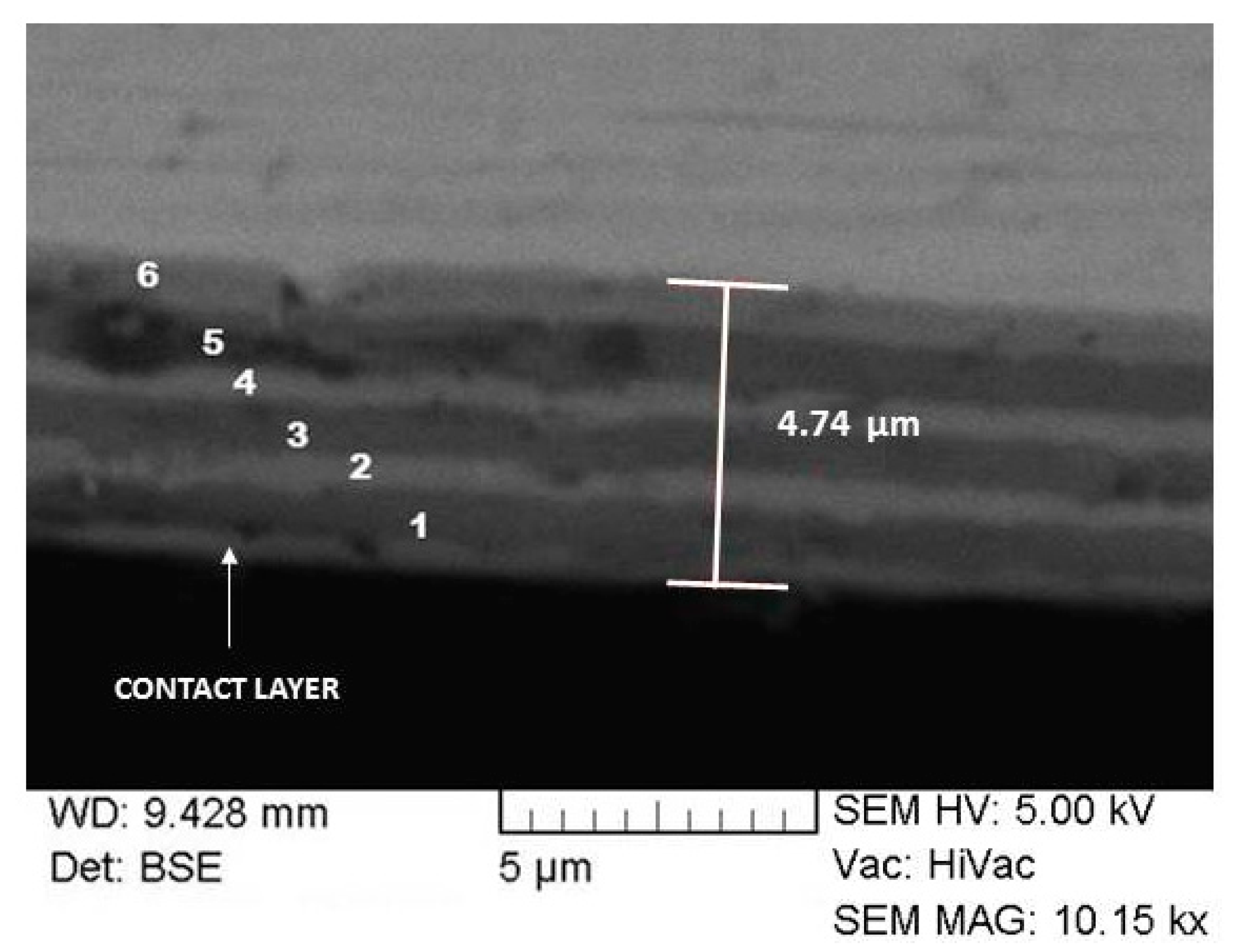
3.1. Thickness

Figure 2 presents the craters formed by the ball-erosion method, which were used for coating thickness determination. The concentric circumferences in Figure 2a present the sublayers forming the modulated structure of the CrAlSiN–AlSiN coating. The innermost light ring with a thickness of 600 nm coincides with the contact layer between the substrate and the first coating period. The rings that follow are assigned to the sublayers of the modulated periods. The light rings correspond to the CrAlSiN sublayers, while the dark ones are the AlSiN sublayers. The thickness of the CrAlSiN and AlSiN sublayers is 610 and 790 nm, respectively. The total thickness of the modulated CrAlSiN–AlSiN coating was determined to be 4.8 µm.
Figure 2b,c presents the images of the abraded craters of the CrAlSiN and AlSiN nanocomposites, respectively. The relevant thicknesses for the above nanocomposites were determined to be 4.4 and 5.0 µm.

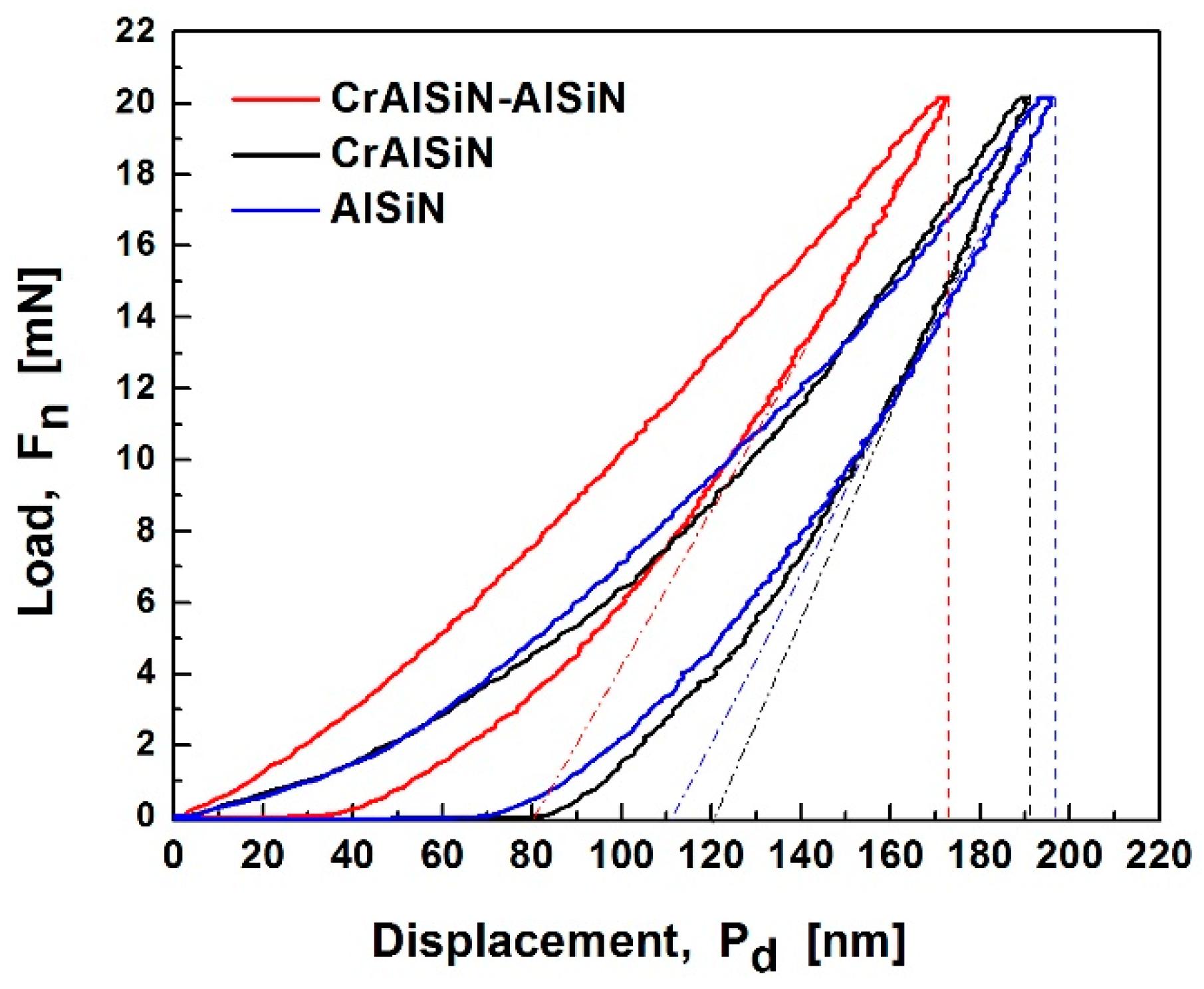
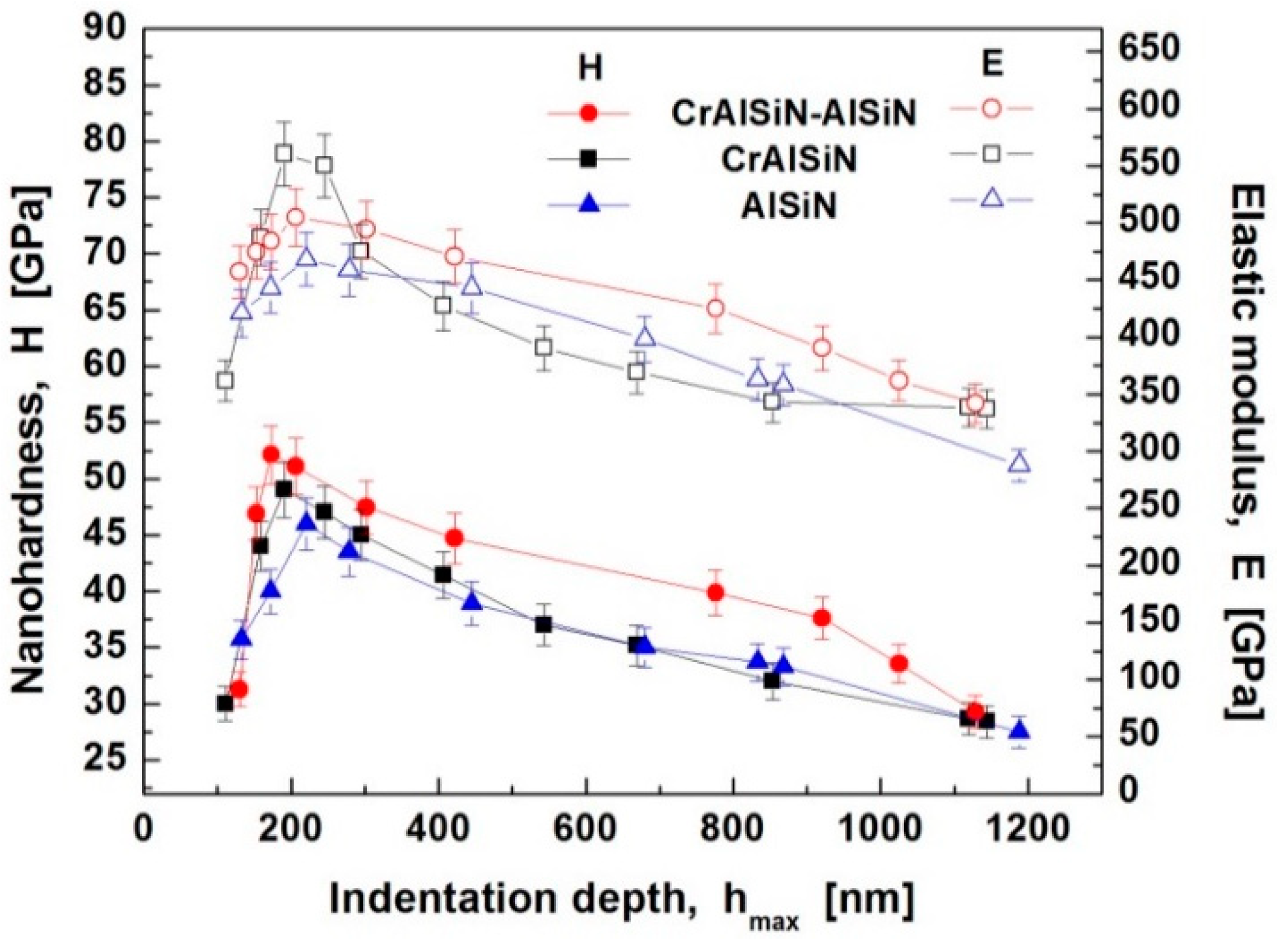
3.2. Mechanical Properties

The loading–unloading curves were measured to determine the parameters characterizing the mechanical properties, nanohardness (H), elastic modulus (E = E*(1 − ν2), E*—the effective elastic modulus, ν—the Poisson ratio), and elastic recovery (We). The measurements were performed on high speed steel HSS coupon specimens with a hardness of 13 GPa. Poisson’s ratio was assumed to be 0.25 [34]. Figure 3 presents the typical loading–unloading curves of the compositionally modulated CrAlSiN–AlSiN coating, and the reference CrAlSiN and AlSiN ones, measured at a load of 20 mN. The area between the unloading curve and the perpendicular to the displacement axis defines the elastic recovery work (We). The different maximum displacement of the indenter into the surface at the same load of 20 mN related to different nanohardnesses. The lower displacement into the CrAlSiN–AlSiN coating indicated higher nanohardness in comparison with the reference CrAlSiN and AlSiN coatings. The load–displacement curve of the compositionally modulated CrAlSiN–AlSiN coating showed the highest elastic recovery work after indentation, implying it has the highest elasticity.
Figure 4 presents the change of the hardness and elastic modulus into the coating depth. The nanohardness of all coatings gradually decreases with the coating depth. Maximum nanohardness of 54, 49, and 46 GPa was determined for the CrAlSiN–AlSiN, CrAlSiN, and AlSiN coatings, respectively. This hardness could be accepted independent of the substrate effect because the corresponding indentation depth is lower than 10% of the coating thickness. The enhanced nanohardness of the coatings could be due to two mechanisms: the solid solution hardening effect, and/or formation of a nanocomposite structure [21,22,35,36,37]. The hardness of the CrAlSiN–AlSiN coating decreases very slowly into the coating depth, and even at a depth of 800 nm, it is still high—40 GPa. The reference AlSiN coating shows the same downward tendency of decrease, from 46 to 34 GPa, in the same indentation depth interval. Both coatings exhibit the same decrease magnitude of 1.35. The hardness of the CrAlSiN nanocomposite reduces more steeply, and at a depth of 800 nm it lowers 1.53 times, from 49 to 32 GPa. We associate this steeper decrease with the lower thickness of the coating. In the indentation depth of 900 to 1200 nm, the hardness of the modulated coating decreases rapidly to 29 GPa, reaching the values of the reference coatings. The observed fast reduction of the calculated coating hardness is caused by the increased influence of the low-hard substrate.
Similarly, the elastic modulus decreases with the increase of the indentation depth and at 1200 nm it reaches values close to the elastic modulus of the substrate (285 GPa). The reference coatings demonstrate behavior typical of superhard nanocomposites, in which the enhanced hardness relates to a high elastic modulus. An elastic modulus of 483, 468, and 560 GPa, corresponding to the maximum hardness, was calculated for the CrAlSiN–AlSiN, AlSiN, and CrAlSiN coatings, respectively (Figure 5a). This result shows that the elastic modulus of the coating with modulated composition is quite low in comparison with the reference CrAlSiN coating, and very close to that of the AlSiN one. We assume that the increased amount of the AlSiN compound in the modulated CrAlSiN–AlSiN coating causes its moderate elastic modulus. Figure 5 presents a comparison between the mechanical properties of the modulated CrAlSiN–AlSiN coating, and the reference CrAlSiN and AlSiN ones. The modulated CrAlSiN–AlSiN coating exhibits the highest H/E* ratio of 0.11, indicating improved elastic strain prior to failure, which relates to improved resistance of the CrAlSiN–AlSiN coating to mechanical degradation under external influence. Ratios of 0.08 and 0.9 were determined for the CrAlSiN and AlSiN nanocomposites, respectively. A high value of the ratio H3/E*2 = 0.72 was determined for the CrAlSiN–AlSiN coating as well, which suggests improved resistance to plastic deformation. The latter leads to an increase in the coating resistance to crack formation and low brittleness. Hence, the high H3/E*2 ratio implies high wear resistance, which is important for the tool reliability in the working process. Elastic recovery of 70%, 54%, and 67% was determined for the CrAlSiN–AlSiN, CrAlSiN, and AlSiN coatings, respectively, which indicates that the coating with a periodically modulated composition featuring the highest elastic recovery possesses high elasticity, improved toughness, and superhardness.

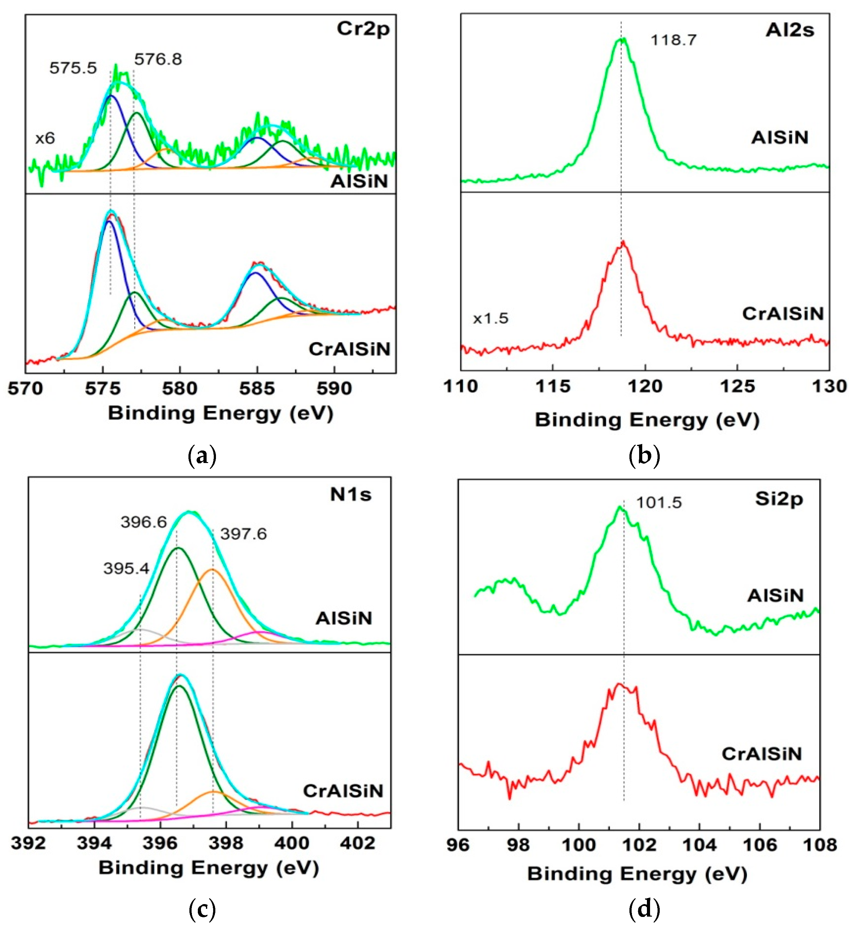
3.3. Composition and Structure

The composition modulation of the CrAlSiN–AlSiN coating was examined by EDX analysis of the cross section in six characteristic points outside the gradient interfaces between the sublayers. The SEM image of the cross-section with well distinguished Cr-rich and Al-rich sublayers is presented in Figure 6. The cross-section reveals excellent coating adhesion to the substrate and cohesion between the sublayers. No delimitations or voids were observed in the coating depth. The coating exhibits a dense structure without any indications of columnar growth. The coating thickness of 4.74 μm, measured by SEM cross-section observation, agrees very well with the value determined using the ball-erosion method.
The element content and the sublayer composition are summarized in Table 1. The composition of the reference coatings is presented as well. The element content makes it possible to consider the coating composition stoichiometric with regard to the N Cr   +   Al   +   Si ratio, which proves that the modulated periods are composed of stoichiometric sublayers. The element composition shows that the Si/Al ratio in the AlSiN sublayers and the corresponding reference coating are lower than that in the CrAlSiN sublayers and the corresponding reference coating. We suggest that this discrepancy is due to re-sputtering, which is intensified at the higher bias voltage used during deposition of the AlSiN sublayers. The ionized Si atoms reaching the surface, are positioned close to the surface, thereby increasing the possibility of re-sputtering by the impinging particles; while the Al atoms reach the surface with higher energy, resulting in subplantation, which decreases the possibility of their re-sputtering [38].
Nevertheless, in both compositions, the Si content is high enough, suggesting a reduction in grain size and formation of an amorphous SiNx phase. The Si content of 7%–8% in the AlSiN composition facilitates the grain size decrease in the film [23]. The detected chromium in the Al-rich sublayers and in the reference coating, is caused by the diffusion process from the adjacent Cr-rich layers during high thermal treatments. As expected, the composition of the Cr-rich and the Al-rich sublayers is consistent with the compositions of the reference CrAlSiN and AlSiN nanocomposites, respectively, because of the same deposition conditions.
Two types of specimens were prepared for the XPS analysis of the Cr-rich and Al-rich sublayers, with CrAlSiN and AlSiN top layers, respectively. The escape depth of the emitted photoelectrons is in the range 1–5 nm, depending on their kinetic energy. Figure 7 illustrates the fitted Cr2p, Al2s, Si2p, and N1s high-resolution photoelectron spectra of the CrAlSiN and AlSiN sublayers.
The peaks of the deconvoluted Cr2p spectra are assigned to different chemical states according to reference data. The peaks centered at 575.5 and 584.8 eV, were recognized as Cr2p3/2 and Cr2p1/2 respectively. They relates to Cr–Al–N bonds, implying the existence of a (Cr,Al)N phase [9,39]. The Cr2p3/2 peak at 576.8 eV was assigned to the Cr–N bond in the Cr2N phase. It should be noted that this peak might correspond to Cr2O3 (usually appearing between 576 and 577 eV) as well [40]. The peak centered at 579.0 eV might be attributed to CrO3. The maximum of the binding energy of Al2p was determined at 74.0 eV (not shown). Because the positions of the Al2p and Cr3s peaks overlap, the Al2s spectrum was measured for clarification. The Al2s peak was identified at binding energy of 118.7 eV, which related to the Al–N bond in AlN or (CrAl)N phases [7,10,41]. The deconvolution of the N1s peak displayed that it consists of 3 components. The main peak at 396.6 eV was identified as nitrogen bonded to aluminum and chromium (Al–N, Cr–N, Cr–Al–N) [9,20]. The peak at 397.6 eV could be assigned to nitrogen in Si–N [20]. The low intensive peak at 395.4 eV is most probably due to N–N defects in Al–N [42]. In the Si2p spectrum, the binding energy for the Si2p level appeared at 101.5 eV, confirming the presence of stoichiometric Si3N4 [43]. Consequently, the XPS measurements identified three types of bonds, Cr–N, Al–N, and Si–N, which dominate in the CrAlSiN–AlSiN coating.
XRD measurements were performed to investigate the coating phase composition. A powder XRD pattern of the modulated CrAlSiN–AlSiN coating is presented in Figure 8a. The sharp peaks of the stainless steel substrate (SS) are referred to a cubic unit cell with parameter 3.5955(5) Å (S.G. Fm-3m). The cubic unit cell parameter of the substrate was 2.867(7) Å (S.G. Im-3m), and the mean crystallite size was determined to be 97 nm. The film comprises two crystalline phases, together with a certain amount of amorphous component. Impurity peaks of individual Cr–Si or Si–N phases were not detected. The first observed crystalline phase is a face-centered cubic CrN-type (S.G. Fm-3m). Preferred (200) orientation centered at 37.48° was detected. The same preferred orientation was reported for CrAlSiN nanocomposite coatings deposited by the same technique [30]. The detected diffraction peaks tend to shift to the smaller angles, compared to the standard PDF cards. The unit cell parameter of 4.155(2) Å of the cubic phase presented in the coating is slightly higher than the unit cell parameters 4.148 Å of pure CrN. We attribute this increase in the lattice parameter to the substitution of the smaller Cr atoms (at.r. 127 pm) by the larger Al atoms (at.r. 143 pm), in the fcc–CrN lattice showing the formation of the fcc–(CrAl)N solid solution [8]. The mean crystallite size of the fcc–(Cr,Al)N phase was determined to be 9 nm. The value of 2.47 × 10⁻³ calculated for the strain parameter indicates that incorporation of Al into the CrN lattice may occur not only by substitutional replacement of Cr, but also by being in interstitial positions.
The second crystalline phase is a hexagonal AlN-type (S.G. P63mc) with preferred (100) orientation of the crystallites, and unit cell parameters of a = b = 3.152(2) Å and c = 5.018(5) Å (“a” and “b” denote the cell parameters along a-axis and b-axis, respectively; “c” is the cell parameter along c-axis). The ratio of the unit cell parameter c/a = 1.59 is a little lower than that of the pure AlN (1.60). This result implies the existence of a bond shorter than the Al–N bond in pure AlN [44]. Among the possible bonds of the Si atoms in the Al–Si–N system, only the Si–N bond is shorter than the Al–N bond [45]. This result suggests that Si atoms (at.r. 134 pm) substitute for the Al atoms in the AlN lattice, and the formation of the (AlSi)N solid solution is possible. However, as a whole, the lattice parameters are higher than the corresponding ones of pure AlN (PDF 00-025-1133), which might be due to the fact that the lattice of the hexagonal phase should match the lattice of the cubic phase in the coating, or incorporate Si in it. Peaks of the hexagonal phase are broader than those of the CrN-type, and the calculated mean crystallite size for the hcp-AlN phase is 7 nm. The strain parameter of this phase was calculated to be 1.7 × 10⁻³.
XRD patterns of the reference CrAlSiN and AlSiN coatings are presented in Figure 8b. The peaks of the substrate (marked SS) correspond to a cubic unit cell with parameter 3.5955(5) Å (S.G. Fm-3m). Both XRD patterns exhibit peaks from different lattice planes, indicating that both coatings are polycrystalline with random grain orientation. The CrAlSiN film comprises of one crystalline phase, which could be recognized as a face-centered cubic (Cr,Al)N [8]. A mean size of 16 nm was calculated for the CrAlN crystallites. No Cr–Si phase was detected in the CrAlSiN coating. The XRD patterns of the AlSiN coating indicate that the film crystallizes in a hexagonal AlN-type (S.G. P63mc). The diffraction peaks could be assigned to the hcp-(AlSi)N phase [45]. A mean crystallite size of 5 nm was determined in the AlSiN coating. No Si–N phase was detected in either coating, which indicates that SiNx might exist in the film in amorphous state.
The XPS and XRD analyses revealed that the CrAlSiN–AlSiN coating is a nanocomposite composed of nanocrystallites embedded in an amorphous matrix. It was found out that the nanocrystalline phase consists of solid solution (CrAl)N and (AlSi)N crystallites, with a mean size of 9 nm and 7 nm, respectively. This refined coating structure causes by the existence of the amorphous Si3N4 phase, which segregates along the (CrAl)N and (AlSi)N crystallite boundaries. The latter is facilitated by the higher Si quantity, which exceeds the solubility limit in the CrN [8] and AlN [45] lattices. Besides, the formed Si3N4 phase interrupts the continuous growth of nitrides, prevents the dislocation and crack propagation, and hampers the grain boundary sliding. Thus, solid solution and nanocomposite hardening occur, which explains the observed enhancement of the coating hardness.
According to the EDS results, the coating composition is periodically modulated from Cr051Al0.41Si0.08N to Al0.82Cr0.04Si0.14N. This means that along the period, two areas could be distinguished: one dominated by Al1−xSixN nanograins, and a second one where Cr1−xAlxN nanograins prevail. The different chemical composition corresponds to different chemical bonds between the elements, each of them having different bond strength. It is known that bond strength affects the physical and mechanical properties of the solid state. Bond strength directly influences the elastic modulus of the material. The higher the bond strength, the higher the elastic modulus of the material is [46]. Among the bonds revealed by the XPS analysis in the CrAlSiN–AlSiN coating, two basic bond types were recognized in the nanocrystalline phase. One of them relates to the stronger Cr–N bond (377.8 ± 18.8 kJ/mol), and the second one is associated with the weaker Al–N bond (297 ± 96 kJ/mol) [47]. Thus, because of the modulation of the coating composition, the elastic modulus is modified as well. We believe that due to the higher Al amount in the composition, the influence of the Al–N bonds is greater, which causes a decrease in the elastic modulus of the modulated CrAlSiN–AlSiN nanocomposite coating, compared to the CrAlSiN nanocomposite.

4. Conclusions

The CrAlSiN–AlSiN coating reported in this study has a nanocomposite structure consisting of an amorphous Si3N4 matrix, in which nanocrystallites with sizes of 9 nm and 7 nm are incorporated. The XRD and XPS analyses revealed that nanocrystallites are composed of (CrAl)N and (AlSi)N. This structure causes enhanced coating hardness of 54 GPa. The coating composition is periodically modulated, as Cr-rich (Cr051Al0.41Si0.08N) and Al-rich (Al0.82Cr0.04Si0.14N) regions are formed in each period. As a result of the modulated composition, the elastic modulus of the coating has a moderate value of 483 GPa, which is much lower than that of the reference Cr054Al0.38Si0.08N nanocomposite, and slightly higher compared to that of the reference Al0.82Cr0.02Si0.16N nanocomposite. The improved elasticity relates to the better elastic recovery of 70%. The CrAlSiN–AlSiN coating exhibits improved elastic strain (H/E* = 0.11) and very good resistance to plastic deformation (H3/E*2 = 0.72). This result implies improved resistance to mechanical degradation and failure under higher stresses, and improved ability to absorb energy at deformation before fracture.
The results of this study showed that the CrAlSiN–AlSiN coating with periodically modulated composition possesses enhanced hardness and improved toughness. The developed coating will be subjected to further research on its surface morphology and coefficient of friction. The effect of the post-deposition thermal treatment, thermal stability, and wear resistance at high temperatures will be investigated as well.

Author Contributions

Conceptualization, L.K. and R.K.; formal analysis, G.A., V.C. and T.C.; investigation, L.K., D.K., G.A., S.R., V.C., T.C. and C.B.; methodology, L.K., R.K. and P.S.; project administration, L.K. and R.K.; resources, R.K.; supervision, L.K.; validation, L.K., R.K., P.S., D.K. and S.R.; visualization, L.K.; writing—original draft, L.K., D.K., G.A. and S.R.; writing—review and editing, L.K., R.K., P.S., D.K. and S.R. All authors have read and agreed to the published version of the manuscript.

Funding

This work was supported by the European Regional Development Fund within the OP “Science and Education for Smart Growth 2014–2020”, Project CoE “National center of mechatronics and clean technologies”, No. BG05M2OP001-1.001-0008-C01.

Conflicts of Interest

The authors declare no conflict of interest.

References

  1. Li, J.; Zhang, S.; Li, M. Influence of the C2H2 flow rate on gradient TiCN films deposited by multi-arc ion plating. Appl. Surf. Sci. 2013, 283, 134–144. [Google Scholar] [CrossRef]
  2. Chang, Y.Y.; Yang, S.J.; Wu, W.; Kuo, Y.C.; Lee, J.W.; Wang, C.J. Mechanical properties of gradient and multi-layered TiAlSiN hard coatings. Thin Solid Films 2009, 9517, 4934–4937. [Google Scholar] [CrossRef]
  3. Faga, M.G.; Gautier, G.; Calzavarini, R.; Perucca, M.; Aimo Boot, E.; Cartasegna, F.; Settineri, L. AlSiTiN nanocomposite coatings developed via Arc Cathodic PVD: Evaluation of wear resistance via tribological analysis and high speed machining operations. Wear 2007, 263, 1306–1314. [Google Scholar] [CrossRef]
  4. Chen, L.; Wang, S.Q.; Du, Y.; Zhou, S.Z.; Gang, T.; Fen, J.C.; Chang, K.K.; Li, Y.W.; Xiong, X. Machining performance of Ti–Al–Si–N coated inserts. Surf. Coat. Technol. 2010, 205, 582–586. [Google Scholar] [CrossRef]
  5. Cheng, Y.H.; Browne, T.; Heckerman, B.; Meletis, E.I. Mechanical and tribological properties of nanocomposite TiSiN coatings. Surf. Coat. Technol. 2010, 204, 2123–2129. [Google Scholar] [CrossRef]
  6. Lukaszkowicz, K.; Sondor, J.; Kriz, A.; Pancielejko, M. Structure, mechanical properties and corrosion resistance of nanocomposite coatings deposited by PVD technology onto the X6CrNiMoTi17-12-2 and X40CrMoV5-1 steel substrates. J. Mater. Sci. 2010, 45, 1629–1637. [Google Scholar] [CrossRef]
  7. Lukaszkowicz, K.; Dobrzanski, L.A.; Kwasny, W.; Labisz, K.; Pancielejko, M. Microstructure and mechanical properties of nanocomposite coatings deposited by cathodic arc evaporation. J. Achiev. Mater. Manuf. Eng. 2010, 42, 156–163. [Google Scholar]
  8. Ding, X.Z.; Zeng, X.T.; Liu, Y.C. Structure and properties of CrAlSiN Nanocomposite coatings deposited by lateral rotating cathode arc. Thin Solid Films 2011, 519, 1894–1900. [Google Scholar] [CrossRef]
  9. Zhang, S.; Wang, L.; Wang, Q.; Li, M. A superhard CrAlSiN superlattice coating deposited by a multi-arc ion plating: I. Microstructure and mechanical properties. Surf. Coat. Technol. 2013, 214, 160–167. [Google Scholar] [CrossRef]
  10. Zhang, S.; Wang, L.; Wang, Q.; Li, M. A superhard CrAlSiN superlattice coating deposited by a multi-arc ion plating: II. Thermal stability and oxidation resistance. Surf. Coat. Technol. 2013, 214, 153–159. [Google Scholar] [CrossRef]
  11. Veprek, S.; Zhang, R.; Veprek-Heijman, M.G.J.; Sheng, S.; Argon, A. Search for ultrahard materials and recent progress in the understanding of hardness enhancement and properties of nanocomposites. Solid State Phenom. 2010, 159, 1–11. [Google Scholar] [CrossRef]
  12. Ritchie, R. The conflicts between strength and toughness. Nat. Mater. 2011, 10, 817–822. [Google Scholar] [CrossRef] [PubMed]
  13. Leynad, A.; Matthews, A. On the significance of the H/E ratio in wear control: A nanocomposite coating approach to optimised tribological behavior. Wear 2000, 246, 1–11. [Google Scholar] [CrossRef]
  14. Musil, J. Hard and superhard nanocomposite coatings. Surf. Coat. Technol. 2000, 125, 322–330. [Google Scholar] [CrossRef]
  15. Su, Y.L.; Yao, S.H. On the performance and application of CrN coating. Wear 1997, 205, 112–119. [Google Scholar] [CrossRef]
  16. Chim, Y.C.; Ding, X.Z.; Zeng, X.T.; Zhang, S. Oxidation resistance of TiN, CrN, TiAlN and CrAlN coatings deposited by lateral rotating cathode arc. Thin Solid Films 2009, 517, 4845–4849. [Google Scholar] [CrossRef]
  17. Park, I.; King, D.; Moore, J.; Kwon, S.; Rha, J.; Kim, K. Microstructures, mechanical properties, and tribological behaviors of Cr–Al–N, Cr–Si–N, and Cr–Al–Si–N coatings. Surf. Coat. Technol. 2007, 201, 5223–5227. [Google Scholar] [CrossRef]
  18. Schlögl, M.; Paulitsch, J.; Keckes, J.; Mayrhofer, P.H. Influence of AlN layers on mechanical properties and thermal stability of Cr-based nitride coatings. Thin Solid Films 2013, 531, 113–118. [Google Scholar] [CrossRef]
  19. Dopita, M.; Rafaja, D.; Wüstefeld, C.; Ruzicka, M.; Klemm, V.; Heger, D.; Schreiber, G.; Sima, M. Interplay of microstructural features in Cr1−xAlxN and Cr1−xyAlxSiyN nanocomposite coatings deposited by cathodic arc evaporation. Surf. Coat. Technol. 2008, 202, 3199–3207. [Google Scholar] [CrossRef]
  20. Wang, Y.X.; Zhang, S.; Lee, J.W.; Lew, W.S.; Sun, D.; Li, B. Toward hard yet tough CrAlSiN coatings via compositional grading. Surf. Coat. Technol. 2013, 231, 346–352. [Google Scholar] [CrossRef]
  21. Ding, J.; Zhang, T.; Kang, M.; Wang, Q.; Kim, K.H. Microstructure, mechanical, oxidation and corrosion properties of the Cr-Al-Si-N coatings deposited by a hybrid sputtering system. Coatings 2017, 7, 119. [Google Scholar] [CrossRef] [Green Version]
  22. Fan, Q.; Liang, Y.; Wu, Z.; Liu, Y.; Wang, T. Microstructure and properties of CrAlSiN coatings deposited by HiPIMS and direct-current magnetron sputtering. Coatings 2019, 9, 512. [Google Scholar] [CrossRef] [Green Version]
  23. Schecker, A.P.; Hug, H.J.; Patscheider, J. Morphology, microstructure evolution and optical properties of Al–Si–N nanocomposite coatings. Surf. Coat. Technol. 2014, 257, 114–120. [Google Scholar] [CrossRef]
  24. Musil, J.; Remnev, G.; Legostaev, V.; Uglov, V.; Lebedynskiy, A.; Lauk, A.; Procházka, J.; Haviar, S.; Smolyanskiy, E. Flexible hard Al–Si–N films for high temperature operation. Surf. Coat. Technol. 2016, 307, 1112–1118. [Google Scholar] [CrossRef]
  25. Jiang, X.; Yang, F.C.; Chen, W.C.; Lee, J.W.; Chang, C.L. Effect of nitrogen-argon flow ratio on the microstructural and mechanical properties of AlSiN thin films prepared by high power impulse magnetron sputtering. Surf. Coat. Technol. 2017, 320, 138–145. [Google Scholar] [CrossRef]
  26. Illana, A.; Almandoz, E.; Fuentes, G.G.; Perez, F.J.; Mato, S. Comparative study of CrAlSiN monolayer and CrN/AlSiN superlattice multilayer coatings: Behavior at high temperature in steam atmosphere. J. Alloys Compd. 2019, 778, 652–661. [Google Scholar] [CrossRef]
  27. Tsai, S.H.; Duh, J.G. Microstructure and mechanical properties of CrAlN/SiNx nanostructure multilayered coatings. Thin Solid Films 2009, 518, 1480–1483. [Google Scholar] [CrossRef]
  28. Wu, W.; Chen, W.; Yang, S.; Lin, Y.; Zhang, S.; Cho, T.Y.; Lee, G.H.; Kwon, S.C. Design of AlCrSiN multilayers and nanocomposite coating for HSS cutting tools. Appl. Surf. Sci. 2015, 351, 803–810. [Google Scholar] [CrossRef]
  29. Hong, Y.S.; Kwon, S.H.; Wang, T.; Kim, D.I.; Choi, J.; Kim, K.H. Effects of Cr interlayer on mechanical and tribological properties of Cr–Al–Si–N nanocomposite coating. Trans. Nonferrous Met. Soc. China 2011, 21, 62–67. [Google Scholar] [CrossRef]
  30. Lin, C.K.; Hsu, C.H.; Kung, S.C. Effect of electroless nickel interlayer on wear behavior of CrN/ZrN multilayer films on Cu-alloyed ductile iron. Appl. Surf. Sci. 2013, 284, 59–65. [Google Scholar] [CrossRef]
  31. Chaliampalias, D.; Pliatsikas, N.; Pavlidou, E.; Kolaklieva, L.; Kakanakov, R.; Vouroutzis, N.; Patsalas, P.; Vourlias, G.; Polychroniadis, E.K. Structural examination of multilayer CrAlSiN/AlSiN coatings deposited by CAD. J. Nano Res. 2017, 48, 62–70. [Google Scholar] [CrossRef]
  32. Oliver, W.C.; Pharr, G.M. An improved technique for determining hardness and elastic modulus using load and displacement sensing indentation experiments. J. Mater. Res. 1992, 7, 1564–1583. [Google Scholar] [CrossRef]
  33. Mikičić, D.; Kunosić, A.; Zlatanović, M. Contact Force determination in abrasive wear test. Tribol. Ind. 2005, 27, 34–37. [Google Scholar]
  34. Chang, Y.; Chang, C.; Wang, D.; Yang, S.; Wu, W. High temperature oxidation resistance of CrAlSiN coatings synthesized by a cathodic arc deposition process. J. Alloys Compd. 2008, 461, 336–341. [Google Scholar] [CrossRef]
  35. Veprek, S.; Veprek-Heijman, M.G.J. The formation and role of interfaces in superhard nc-MenN/a-Si3N4 nanocomposites. Surf. Coat. Technol. 2007, 201, 6064–6070. [Google Scholar] [CrossRef]
  36. Veprek, S.; Veprek-Heijman, M.G.J.; Karvankova, P.; Prochazka, J. Different approaches to superhard coatings and nanocomposites. Thin Solid Films 2005, 476, 1–29. [Google Scholar] [CrossRef]
  37. Schmitt, T.; Steyer, P.; Fontaine, J.; Mary, N.; Esnouf, C.; O’Sullivan, M.; Sanchette, F. Cathodic arc deposited (Cr,Six)N coatings: From solid solution to nanocomposite structure. Surf. Coat. Technol. 2012, 213, 117–125. [Google Scholar] [CrossRef]
  38. Flink, A.; Larsson, T.; Sjolen, J.; Karlsson, L.; Hultman, L. Influence of Si on the microstructure of arc evaporated (Ti,Si)N thin films; evidence for cubic solid solutions and their thermal stability. Surf. Coat. Technol. 2005, 200, 1535–1542. [Google Scholar] [CrossRef]
  39. Chen, W.; Lin, Y.; Zheng, J.; Zhang, S.; Liu, S.; Kwon, S.C. Preparation and characterization of CrAlN/TiAlSiN nano-multilayers by cathodic vacuum arc. Surf. Coat. Technol. 2015, 265, 205–211. [Google Scholar] [CrossRef]
  40. Conde, A.; Cristóbal, A.B.; Fuentes, G.; Tate, T.; de Damborene, J. Surface analysis of electrochemically stripped CrN coatings. Surf. Coat. Technol. 2006, 201, 3588–3595. [Google Scholar] [CrossRef] [Green Version]
  41. Bobzin, K.; Brögelmann, T.; Grundmeier, G.; Arcos, T.; Wiesing, M.; Kruppe, N. (Cr,Al)N/(Cr,Al)ON oxy-nitride coatings deposited by hybrid dcMS/HPPMS for plastics processing applications. Surf. Coat. Technol. 2016, 308, 394–403. [Google Scholar] [CrossRef]
  42. Rosenberger, L.; Baird, R.; McCullen, E.; Aunern, G.; Shreve, G. XPS analysis of aluminum nitride films deposited by plasma source molecular beam epitaxy. Surf. Interface Anal. 2008, 40, 1254–1261. [Google Scholar] [CrossRef]
  43. Tan, S.; Zhang, X.; Wu, X.; Fang, F.; Jiang, J. Effect of substrate bias and temperature on magnetron sputtered CrSiN films. Appl. Surf. Sci. 2011, 257, 1850–1853. [Google Scholar] [CrossRef]
  44. Lewin, E.; Loch, D.; Montagne, A.; Ehiasarian, A.P.; Patscheider, J. Comparison of Al–Si–N nanocomposite coatings deposited by HIPIMS and DC magnetron sputtering. Surf. Coat. Technol. 2013, 232, 680–689. [Google Scholar] [CrossRef]
  45. Pelisson, A.; Parlinska-Wojtan, M.; Hug, H.J.; Patscheider, J. Microstructure and mechanical properties of Al–Si–N transparent hard coatings deposited by magnetron sputtering. Surf. Coat. Technol. 2007, 202, 884–889. [Google Scholar] [CrossRef]
  46. Padmavathi, D.A. Potential Energy Curves & Material Properties. Mater. Sci. Appl. 2011, 2, 97–104. [Google Scholar] [CrossRef] [Green Version]
  47. Lide, D.R. CRC Handbook of Chemistry and Physics, 79th ed.; CRC Press LLC, N.W.: Boca Raton, FL, USA, 1998; pp. 51–53. [Google Scholar]
Figure 1. A scheme of the coating deposition in the chamber of the machine Platit π80+.
Coatings 10 00041 g001
Figure 2. An image of the calotest crater of: (a) a compositionally modulated CrAlSiN–AlSiN coating; (b) a CrAlSiN nanocomposite; and (c) an AlSiN nanocomposite.
Coatings 10 00041 g002
Figure 3. Typical loading–unloading curves of CrAlSiN–AlSiN, CrAlSiN, and AlSiN coatings.
Coatings 10 00041 g003
Figure 4. Dependence of the nanohardness on the indentation depth of the compositionally modulated CrAlSiN–AlSiN, CrAlSiN, and AlSiN nanocomposites.
Coatings 10 00041 g004
Figure 5. Comparison of the mechanical properties of CrAlSiN–AlSiN, CrAlSiN, and AlSiN coatings: (a) hardness and an elastic modulus; (b) elastic strain to failure and resistance to plastic deformation; (c) elastic recovery.
Coatings 10 00041 g005
Figure 6. A SEM cross-section image of the compositionally modulated CrAlSiN–AlSiN coating.
Coatings 10 00041 g006
Figure 7. XPS (a) Cr2p, (b) Al2s, (c) N1s, and (d) Si2p spectrta of the CrAlSiN and AlSIN films of the modulated coating.
Coatings 10 00041 g007
Figure 8. XRD pattern of the (a) modulated CrAlSiN–AlSiN coating and (b) reference CrAlSiN and AlSiN coatings.
Coatings 10 00041 g008
Table 1. Element composition of the modulated CrAlSiN–AlSiN and reference CrAlSiN and AlSiN coatings.
CoatingPeriod/SublayerElement Concentration, at.%Elemental Composition
NAlCrSi
CrAlSiN–AlSiNCrAlSiN4921264Cr051Al0.41Si0.08N
AlSiN504147Al0.82Cr0.04Si0.14N
CrAlSiN5019274Cr0.54Al0.38Si0.08N
AlSiN504127Al0.82Cr0.04Si0.14N
CrAlSiN5120254Cr0.51Al0.41Si0.08N
AlSiN504037Al0.80Cr0.06Si0.14N
CrAlSINCrAlSiN5019274Cr0.54Al0.38Si0.08N
AlSiNAlSiN504118Al0.82Cr0.02Si0.16N

