Tribological Properties of Polyether–Ether–Ketone-Based Coating under Mixed and Boundary Aviation Kerosene-Lubrication Condition


Abstract
:1. Introduction
2. Experiments
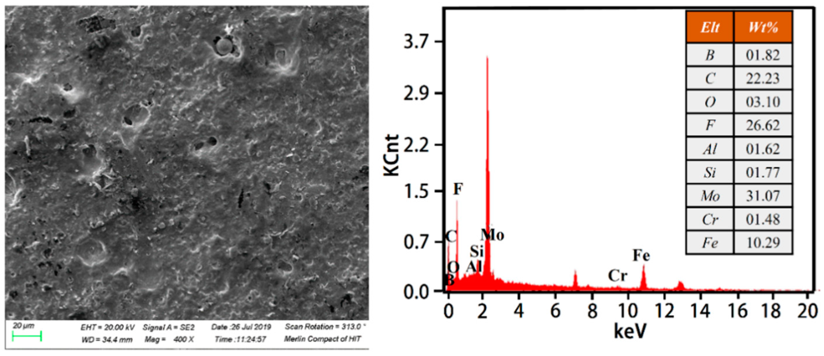
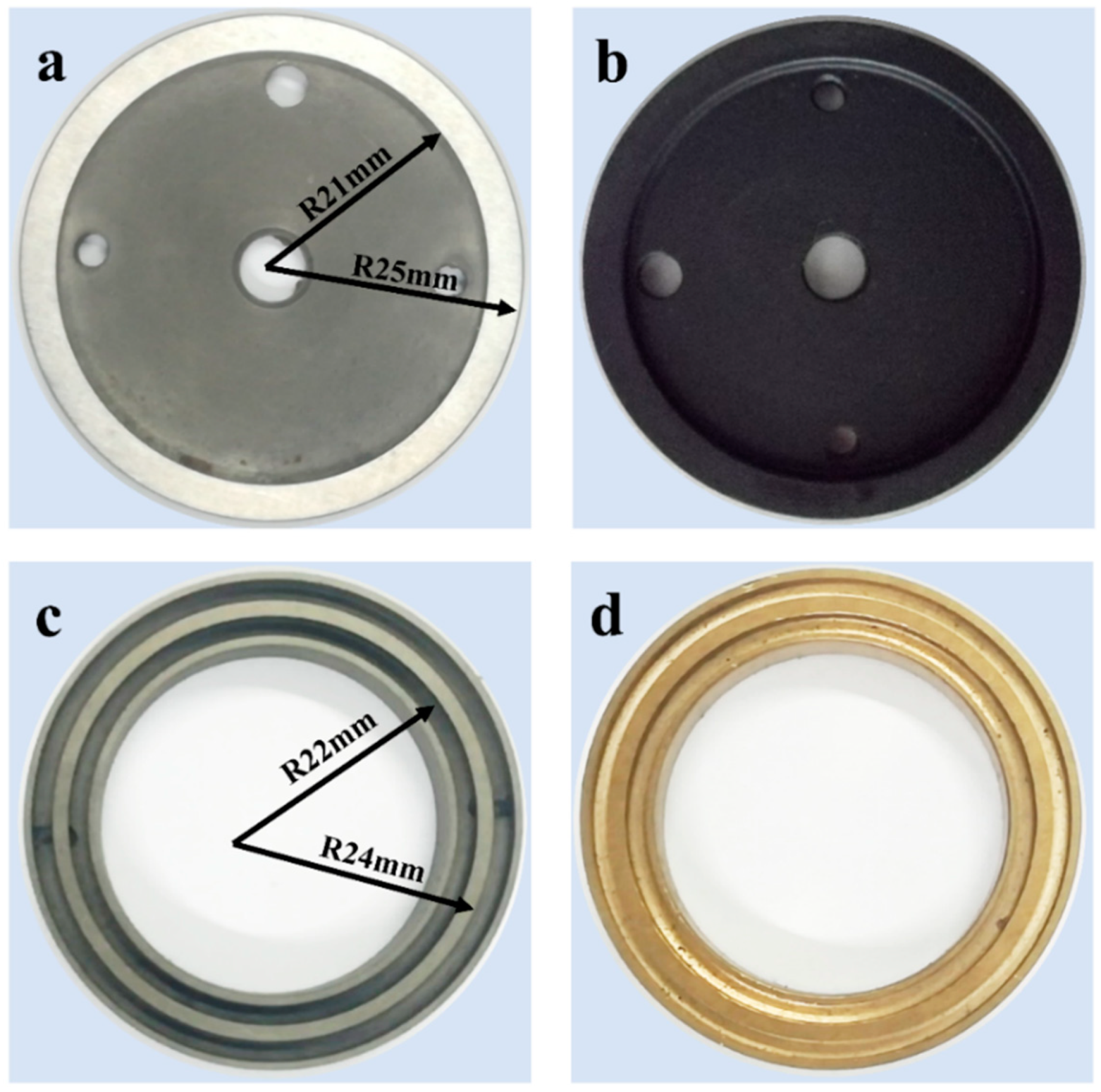
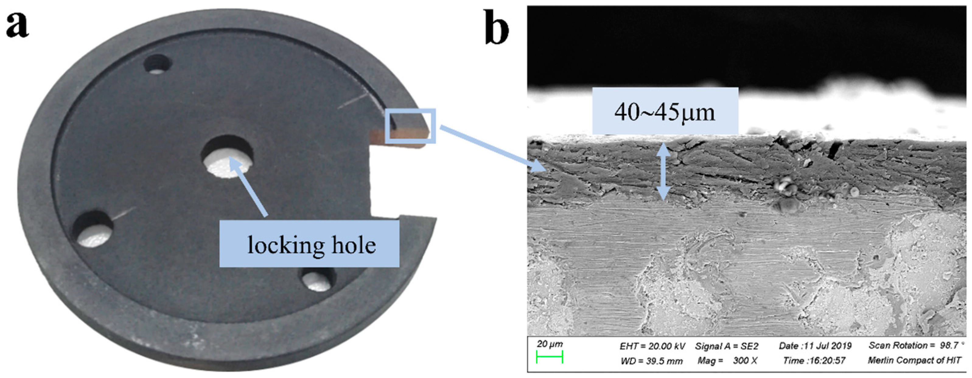
2.1. Material Preparation
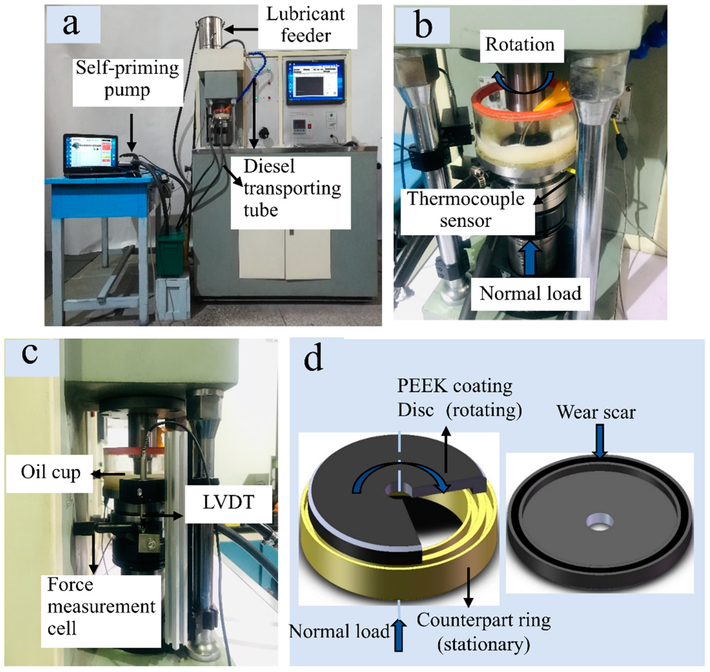
2.2. Friction Test
3. Results and Discussions
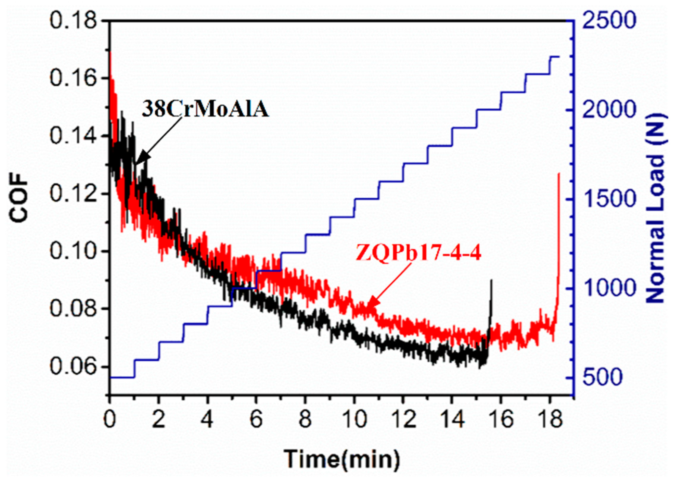
3.1. Scuffing Test
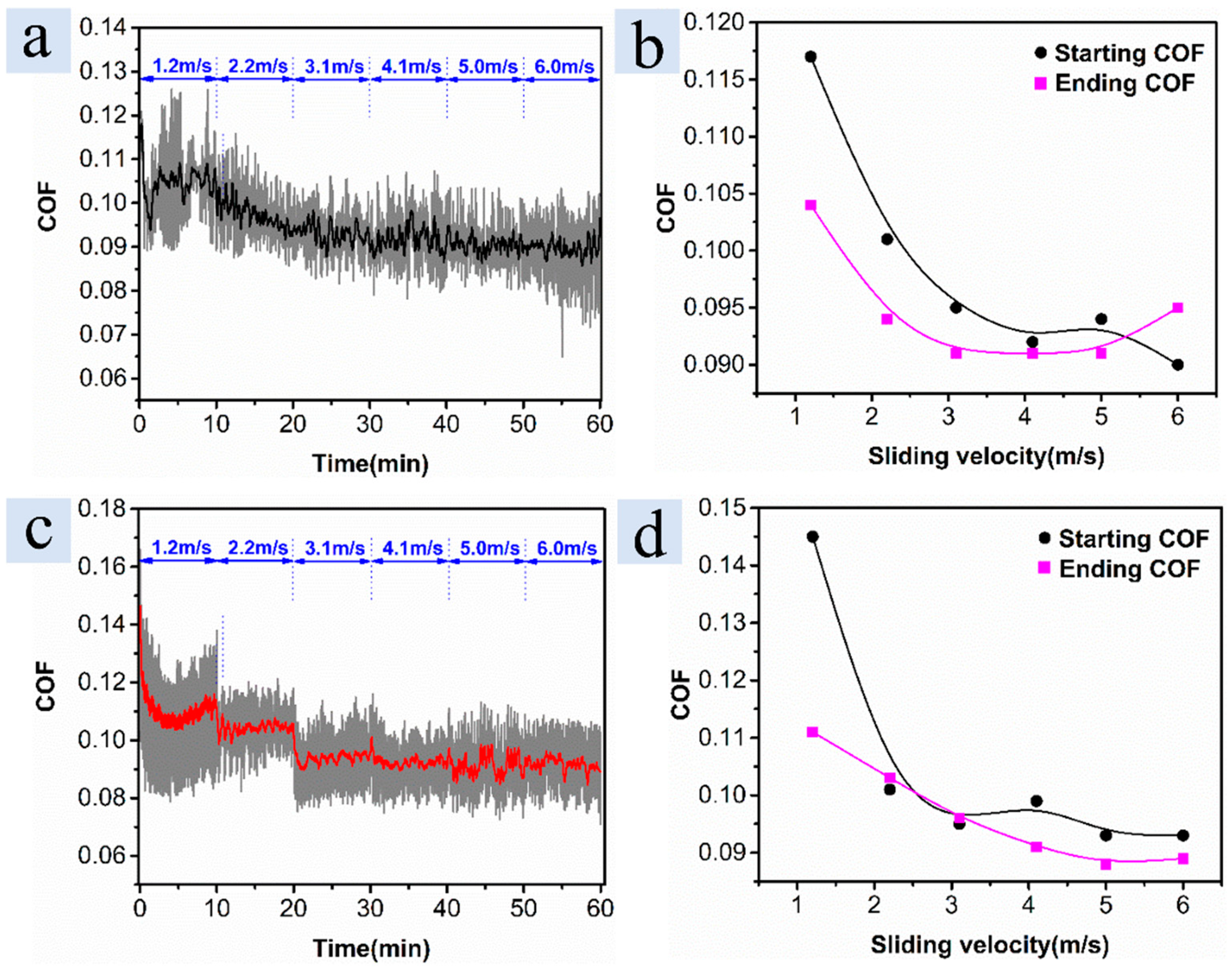
3.2. Stribeck Curve Test
3.3. Constant Load Test: 1000 N (3.46 MPa), 2200 r/min (5.3 m/s)
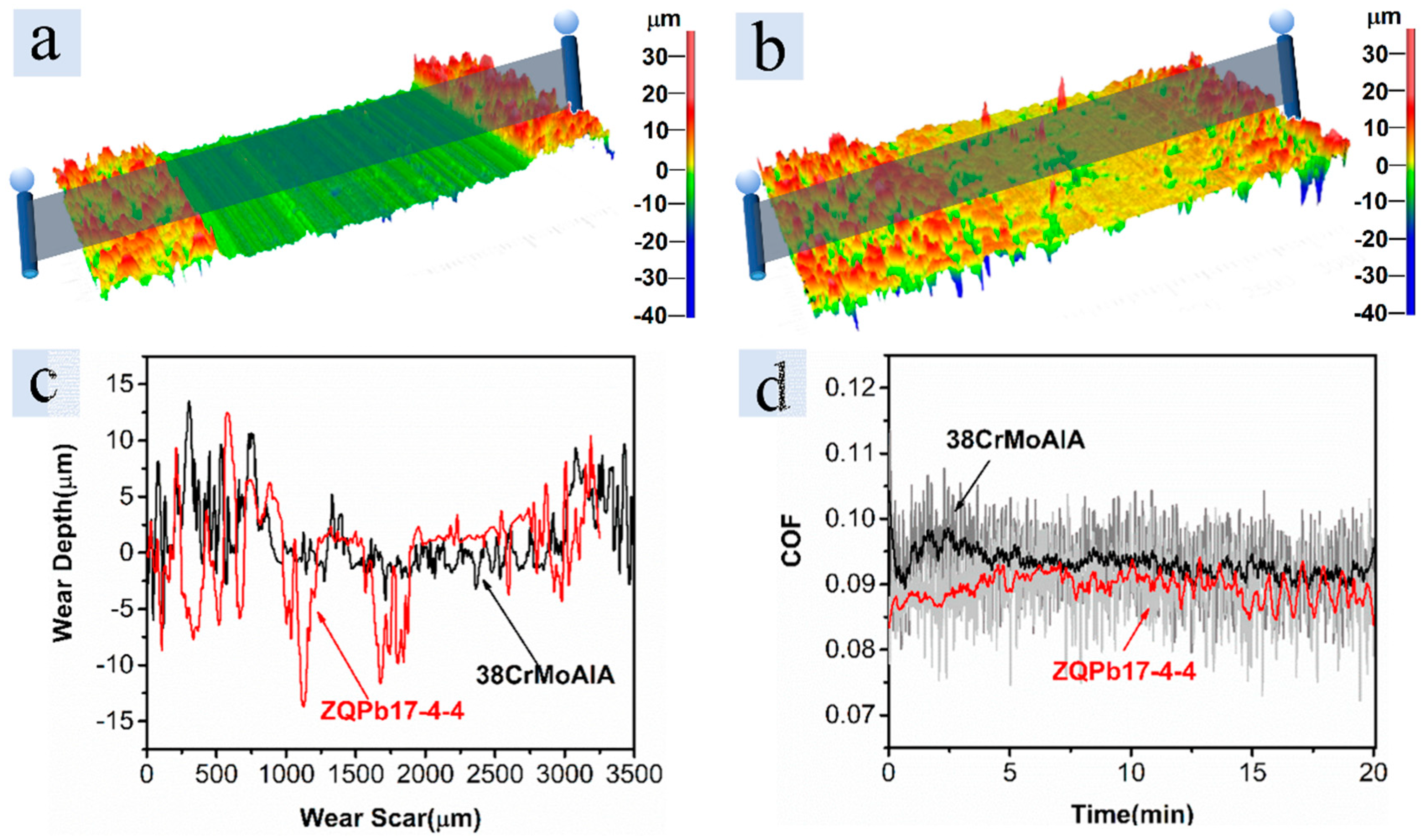
3.3.1. Short Test
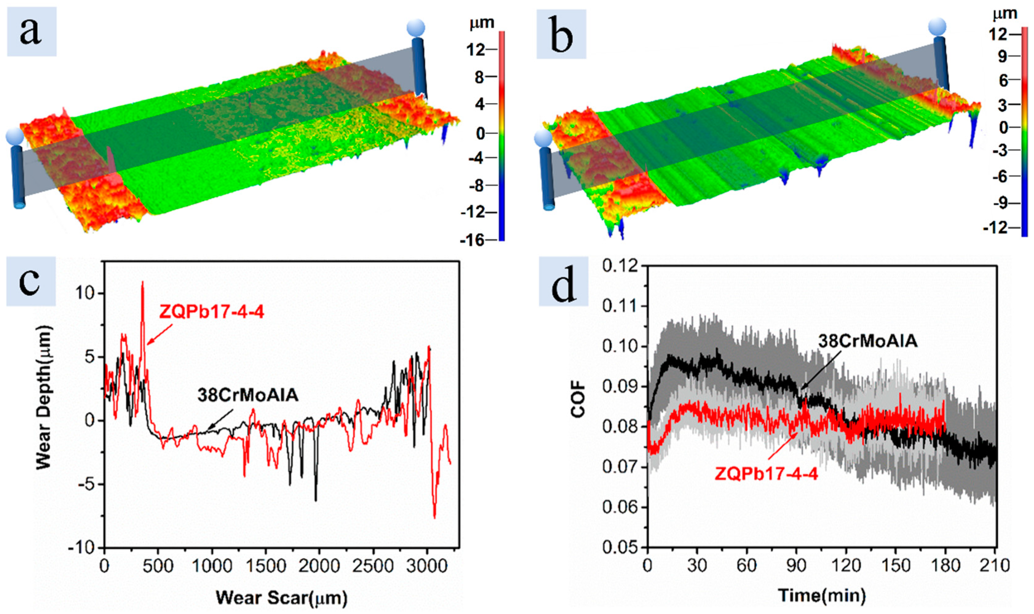
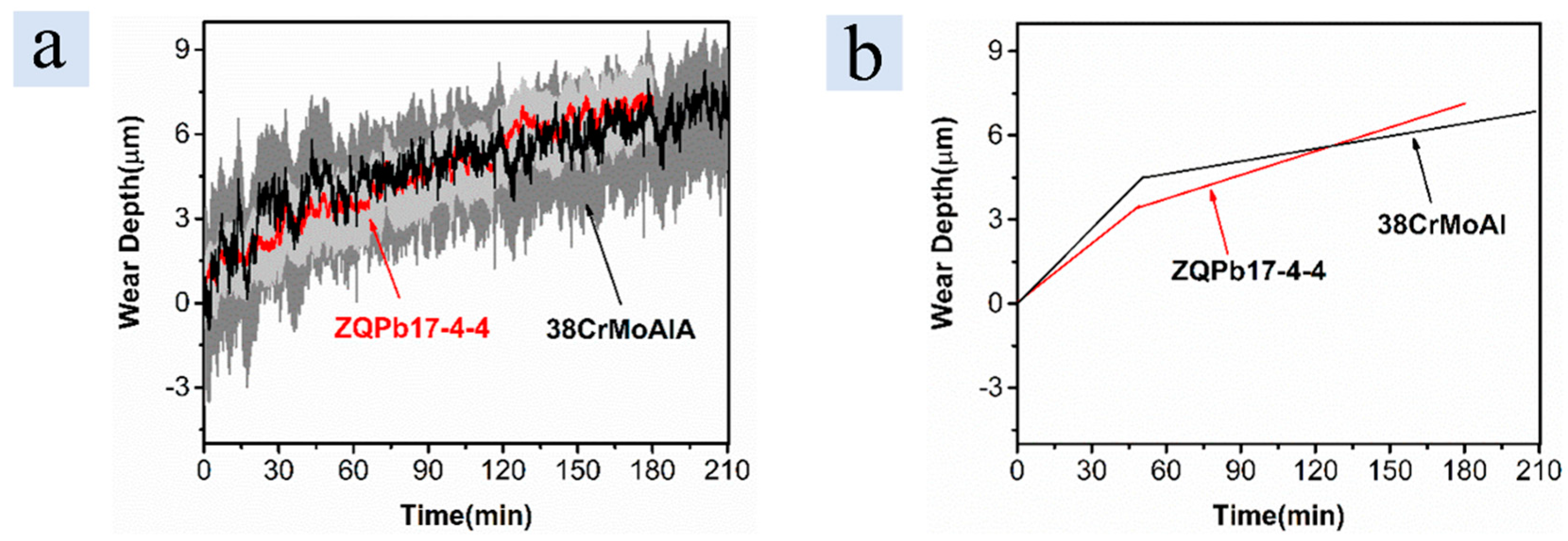
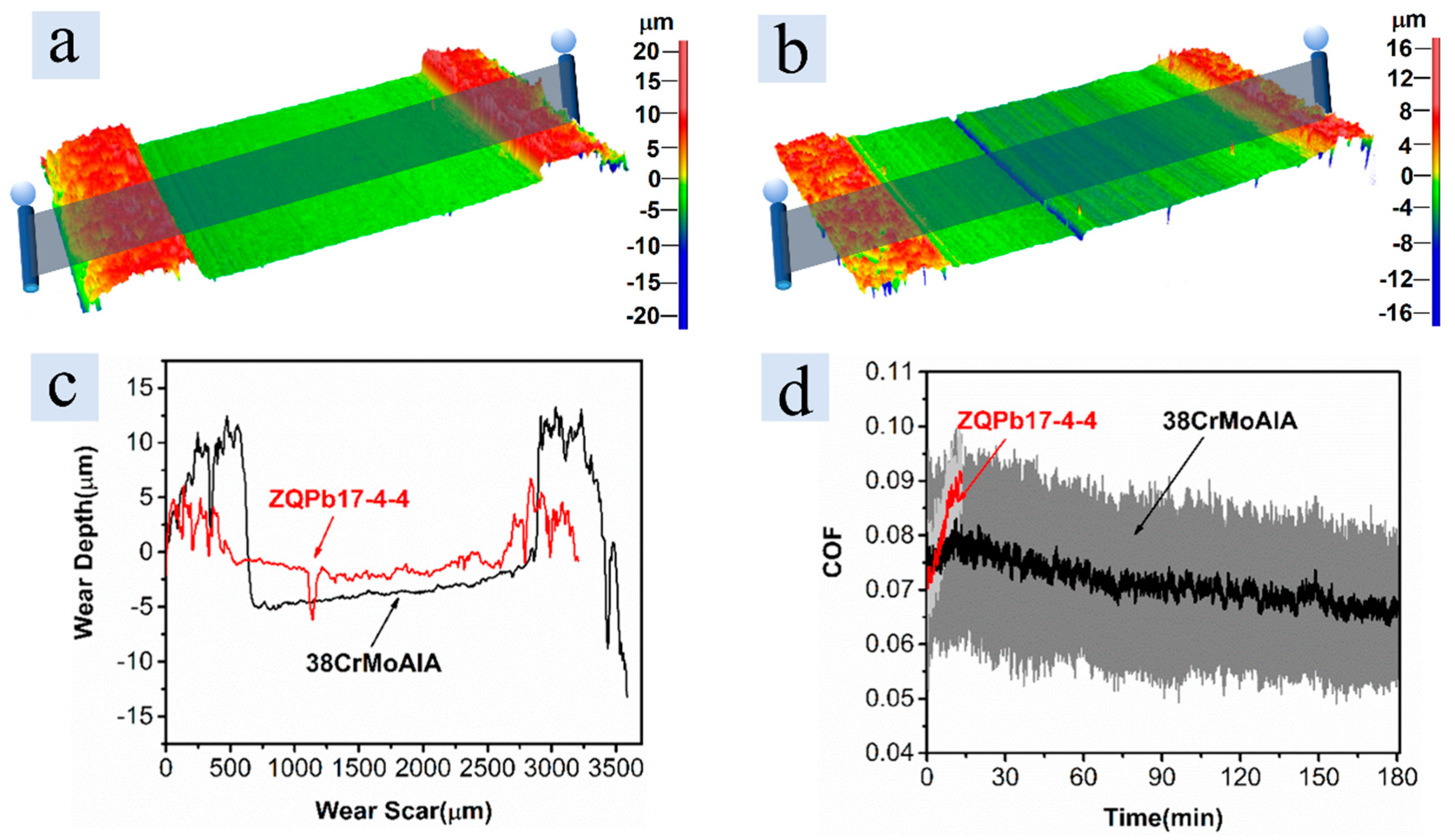
3.3.2. Long Test
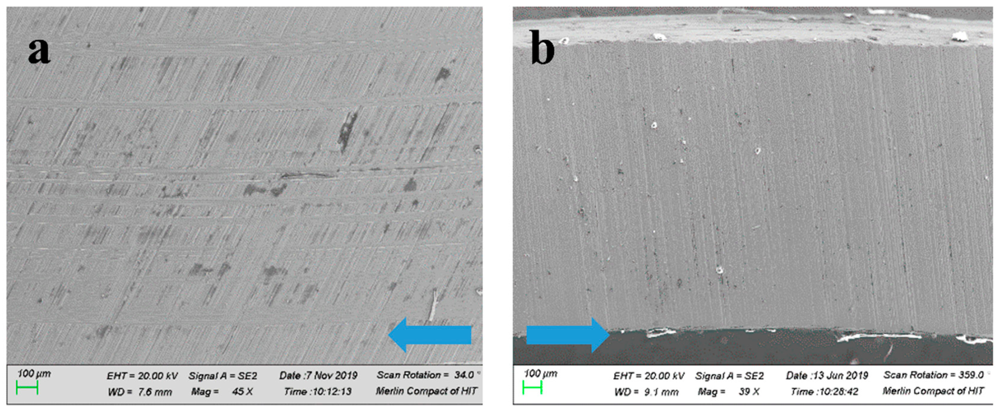
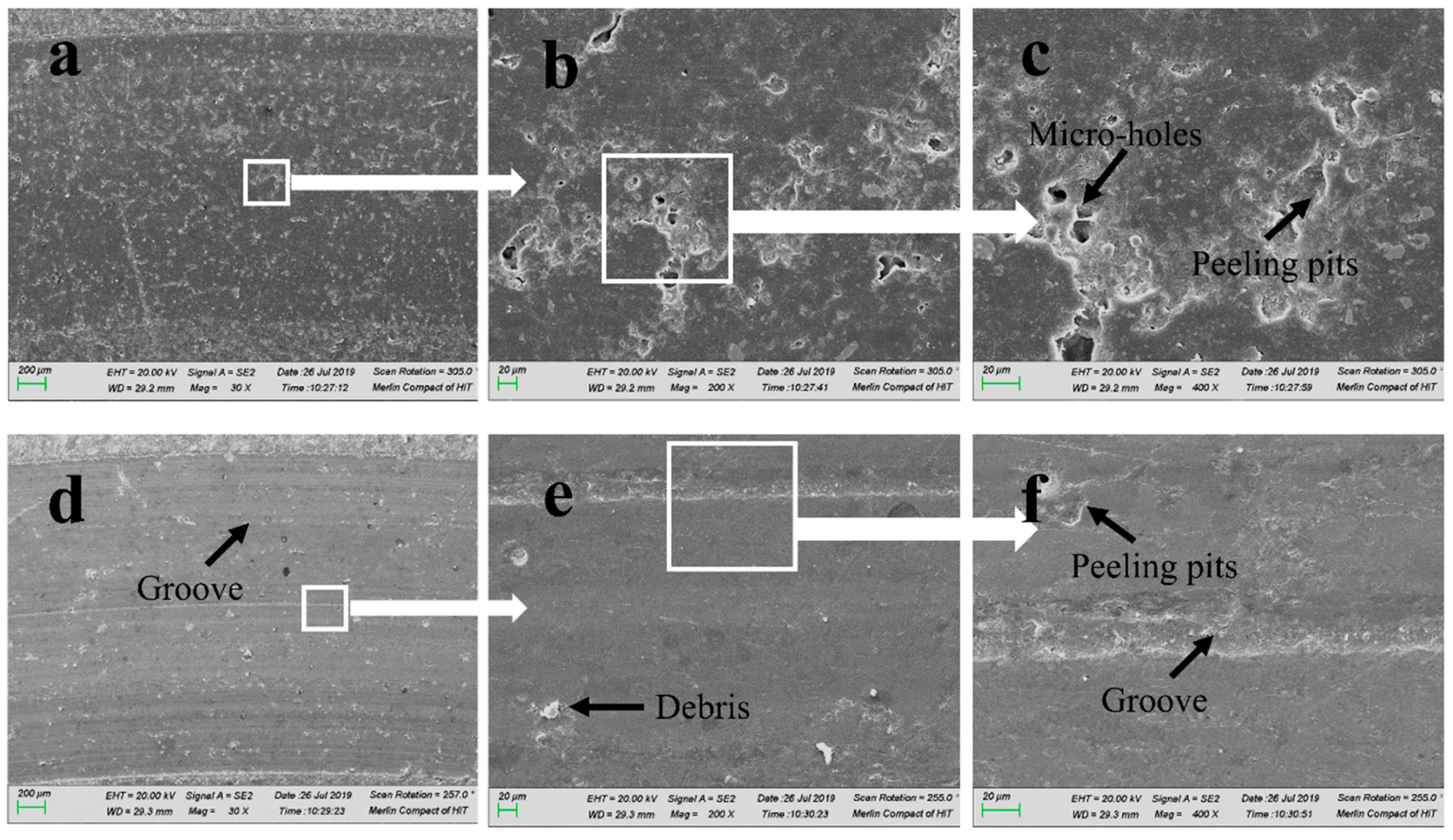
3.3.3. SEM Analysis
3.4. Strengthened Load Test: 1300 N (4.50 Mpa), 2200 r/min (5.3 m/s)
4. Conclusions
- (1)
- Scuffing experiments showed that the PEEK-based coating had a good scuffing resistance against the 38CrMoAlA and ZQPb17-4-4 counterparts. It is presumed that the PEEK-based coating acted as a solid lubricant between the sliding pairs.
- (2)
- The Stribeck curve test showed that the lubrication state of the PEEK-based coating against the counterparts was related closely to the tribofilm, and compared with ZQPb17-4-4, the PEEK-based coating against 38CrMoAlA was more likely to enter the mixed lubrication state from the boundary lubrication state.
- (3)
- In the constant load short test, the PEEK-based coating had a lower wear rate with ZQPb17-4-4. However, in the long test, the PEEK-based coating against 38CrMoAlA had a better performance with a smaller friction coefficient and a lower wear rate. Especially in the special stage, the wear rate was only 1/5 of the running-in stage.
- (4)
- In the strengthened load test, the friction and wear performance of the PEEK-based coating against 38CrMoAlA was far better than that against ZQPb17-4-4, so the friction pair that is composed of the PEEK-based coating and 38CrMoAlA is more competent for use in fuel pumps.
Author Contributions
Funding
Conflicts of Interest
References
- Dowson, D.; Higginson, G.R. A numerical solution to the elasto-hydrodynamic problem. J. Mech. Eng. Sci. 1959, 1, 6–15. [Google Scholar] [CrossRef]
- Furey, M.J. The formation of polymeric films directly on rubbing surfaces to reduce wear. Wear 1973, 26, 369–392. [Google Scholar] [CrossRef]
- Bahadur, S. The development of transfer layers and their role in polymer tribology. Wear 2000, 245, 92–99. [Google Scholar] [CrossRef]
- Bijwe, J.; Rajesh, J.J.; Jeyakumar, A.; Ghosh, A.; Tewari, U.S. Influence of solid lubricants and fibre reinforcement on wear behaviour of polyethersulphone. Tribol. Int. 2000, 33, 697–706. [Google Scholar] [CrossRef]
- Bahadur, S.; Polineni, V.K. Tribological studies of glass fabric-reinforced polyamide composites filled with CuO and PTFE. Wear 1996, 200, 95–104. [Google Scholar] [CrossRef]
- Cenna, A.A.; Dastoor, P.; Beehag, A.; Page, N.W. Effects of graphite particle addition upon the abrasive wear of polymer surfaces. J. Mater. Sci. 2001, 36, 891–900. [Google Scholar] [CrossRef]
- Jacobs, O.; Jaskulka, R.; Yan, C.; Wu, W. On the effect of counterface material and aqueous environment on the sliding wear of carbon fibre reinforced polyetheretherketone (PEEK). Tribol. Lett. 2005, 19, 319–329. [Google Scholar] [CrossRef]
- Kukureka, S.N.; Hooke, C.J.; Rao, M.; Liao, P.; Chen, Y.K. The effect of fibre reinforcement on the friction and wear of polyamide 66 under dry rolling–sliding contact. Tribol. Int. 1999, 32, 107–116. [Google Scholar] [CrossRef]
- Durand, J.M.; Vardavoulias, M.; Jeandin, M. Role of Reinforcing Ceramic Particles in the Wear Behavior of Polymer-Based Model Composites. Wear 1995, 181, 833–839. [Google Scholar] [CrossRef]
- Wang, Q.H.; Xue, Q.J.; Liu, W.M.; Chen, J.M. The friction and wear characteristics of nanometer SiC and polytetrafluoroethylene filled polyetheretherketone. Wear 2000, 243, 140–146. [Google Scholar] [CrossRef]
- Werner, P.; Altstadt, V.; Jaskulka, R.; Jacobs, O.; Sandler, J.K.W.; Shaffer, M.S.P.; Windle, A.H. Tribological behaviour of carbon-nanofibre-reinforced poly(ether ether ketone). Wear 2004, 257, 1006–1014. [Google Scholar] [CrossRef]
- Zhang, L.G.; Li, G.T.; Guo, Y.X.; Qi, H.M.; Che, Q.L.; Zhang, G. PEEK reinforced with low-loading 2D graphitic carbon nitride nanosheets: High wear resistance under harsh lubrication conditions. Compos. Part A Appl. Sci. Manuf. 2018, 109, 507–516. [Google Scholar] [CrossRef]
- Nie, S.L.; Lou, F.L.; Ji, H.; Yin, F.L. Tribological Performance of CF-PEEK Sliding against 17-4PH Stainless Steel with Various Cermet Coatings for Water Hydraulic Piston Pump Application. Coatings 2019, 9, 436. [Google Scholar] [CrossRef] [Green Version]
- Xie, G.Y.; Sui, G.X.; Yang, R. Effects of potassium titanate whiskers and carbon fibers on the wear behavior of polyetheretherketone composite under water lubricated condition. Compos. Sci. Technol. 2011, 71, 828–835. [Google Scholar] [CrossRef]
- Jia, J.; Chen, J.; Zhou, H.; Hu, L. Comparative study on tribological behaviors of polyetheretherketone composite reinforced with carbon fiber and polytetrafluoroethylene under water-lubricated and dry-sliding against stainless steel. Tribol. Lett. 2004, 17, 231–238. [Google Scholar] [CrossRef]
- Sumer, M.; Unal, H.; Mimaroglu, A. Evaluation of tribological behaviour of PEEK and glass fibre reinforced PEEK composite under dry sliding and water lubricated conditions. Wear 2008, 265, 1061–1065. [Google Scholar] [CrossRef]
- Unal, H.; Mimaroglu, A. Friction and wear characteristics of PEEK and its composite under water lubrication. J. Reinf. Plast. Compos. 2006, 25, 1659–1667. [Google Scholar] [CrossRef]
- Chen, B.B.; Wang, J.Z.; Yan, F.Y. Comparative investigation on the tribological behaviors of CF/PEEK composites under sea water lubrication. Tribol. Int. 2012, 52, 170–177. [Google Scholar] [CrossRef]
- Wang, Q.H.; Xue, Q.J.; Liu, W.M.; Chen, J.M. Tribological characteristics of nanometer Si3N4 filled poly(ether ether ketone) under distilled water lubrication. J. Appl. Polym. Sci. 2001, 79, 1394–1400. [Google Scholar] [CrossRef]
- Zhang, G.; Wetzel, B.; Wang, Q. Tribological behavior of PEEK-based materials under mixed and boundary lubrication conditions. Tribol. Int. 2015, 88, 153–161. [Google Scholar] [CrossRef]
- Lan, P.X.; Meyer, J.L.; Vaezian, B.; Polycarpou, A.A. Advanced polymeric coatings for tilting pad bearings with application in the oil and gas industry. Wear 2016, 354–355, 10–20. [Google Scholar] [CrossRef]
- Lan, P.X.; Polychronopoulou, K.; Zhang, Y.F.; Polycarpou, A.A. Three-body abrasive wear by (silica) sand of advanced polymeric coatings for tilting pad bearings. Wear 2017, 382, 40–50. [Google Scholar] [CrossRef]
- Yeo, S.M.; Polycarpou, A.A. Tribological performance of PTFE- and PEEK-based coatings under oil-less compressor conditions. Wear 2012, 296, 638–647. [Google Scholar] [CrossRef]
- Friedrich, K. Wear of reinforced polymers by different abrasive counterparts. In Composite Materials Series; Elsevier: Amsterdam, The Netherlands, 1986; Volume 1, pp. 233–287. [Google Scholar] [CrossRef]
- Mortimer, B.; Lancaster, J.K. Extending the life of aerospace dry bearings by the use of hard smooth counterfaces. Wear 1988, 121, 289–305. [Google Scholar] [CrossRef]
- Nunez, E.E.; Gheisari, R.; Polycarpou, A.A. Tribology review of blended bulk polymers and their coatings for high-load bearing applications. Tribol. Int. 2019, 129, 92–111. [Google Scholar] [CrossRef]
- Voort, J.V.; Bahadur, S. The Growth and Bonding of Transfer Film and the Role of Cus and Ptfe in the Tribological Behavior of Peek. Wear 1995, 181, 212–221. [Google Scholar] [CrossRef]
- Bahadur, S.; Sunkara, C. Effect of transfer film structure, composition and bonding on the tribological behavior of polyphenylene sulfide filled with nano particles of TiO2, ZnO, CuO and SiC. Wear 2005, 258, 1411–1421. [Google Scholar] [CrossRef]
- Fischer, T.E.; Tomizawa, H. Interaction of Tribochemistry and Microfracture in the Friction and Wear of Silicon-Nitride. Wear 1985, 105, 29–45. [Google Scholar] [CrossRef]
- Wei, J.J.; Xue, Q.J. Tribochemical Mechanisms of Si3n4 with Additives. Wear 1993, 162, 1068–1072. [Google Scholar] [CrossRef]
- Laux, K.A.; Jean-Fulcrand, A.; Sue, H.J.; Bremner, T.; Wong, J.S.S. The influence of surface properties on sliding contact temperature and friction for polyetheretherketone (PEEK). Polymer 2016, 103, 397–404. [Google Scholar] [CrossRef] [Green Version]


| Material | Hardness | Thickness (μm) | Roughness, Rq (μm) |
|---|---|---|---|
| QT600-3 | 600 HV | - | 0.52 |
| PEEK-based coating | 160 HV | 43 | 2.8 |
| 38CrMoAlA | 720 HV | - | 0.36 |
| ZQPb17-4-4 | 310 HV | - | 0.36 |
| Test Type | Load (N) | Speed (r/min) | Length of Time (min) |
|---|---|---|---|
| Scuffing | Step load 100 N/min | 2000 | Until the end of the test |
| Stribeck curve | 300 | Step speed 400 r/10 min | 60 |
| Constant load | 1000 | 2200 | Short test for 20 min; long test against 38CrMoAlA for 210 min, against ZQPb17-4-4 for 180 min |
| Strengthened load | 1300 | 2200 | No more than 180 min |
| PEEK-Based Coating | Running-in ws (mm3N−1m−1) × 10−8 | Stable ws (mm3N−1m−1) × 10−8 | Special Friction Coefficient |
|---|---|---|---|
| against 38CrMoAlA | 8.2 | 1.4 | 0.075 |
| against ZQPb17-4-4 | 6.3 | 2.7 | 0.081 |
© 2019 by the authors. Licensee MDPI, Basel, Switzerland. This article is an open access article distributed under the terms and conditions of the Creative Commons Attribution (CC BY) license (http://creativecommons.org/licenses/by/4.0/).
Share and Cite
Jiang, J.; Zhao, C.; Li, G. Tribological Properties of Polyether–Ether–Ketone-Based Coating under Mixed and Boundary Aviation Kerosene-Lubrication Condition. Coatings 2020, 10, 1. https://doi.org/10.3390/coatings10010001
Jiang J, Zhao C, Li G. Tribological Properties of Polyether–Ether–Ketone-Based Coating under Mixed and Boundary Aviation Kerosene-Lubrication Condition. Coatings. 2020; 10(1):1. https://doi.org/10.3390/coatings10010001
Chicago/Turabian StyleJiang, Jihai, Cunran Zhao, and Geqiang Li. 2020. "Tribological Properties of Polyether–Ether–Ketone-Based Coating under Mixed and Boundary Aviation Kerosene-Lubrication Condition" Coatings 10, no. 1: 1. https://doi.org/10.3390/coatings10010001