Four-Channel Ultrasonic Sensor for Bulk Liquid and Biochemical Surface Interrogation


Abstract
1. Introduction
2. Materials and Methods
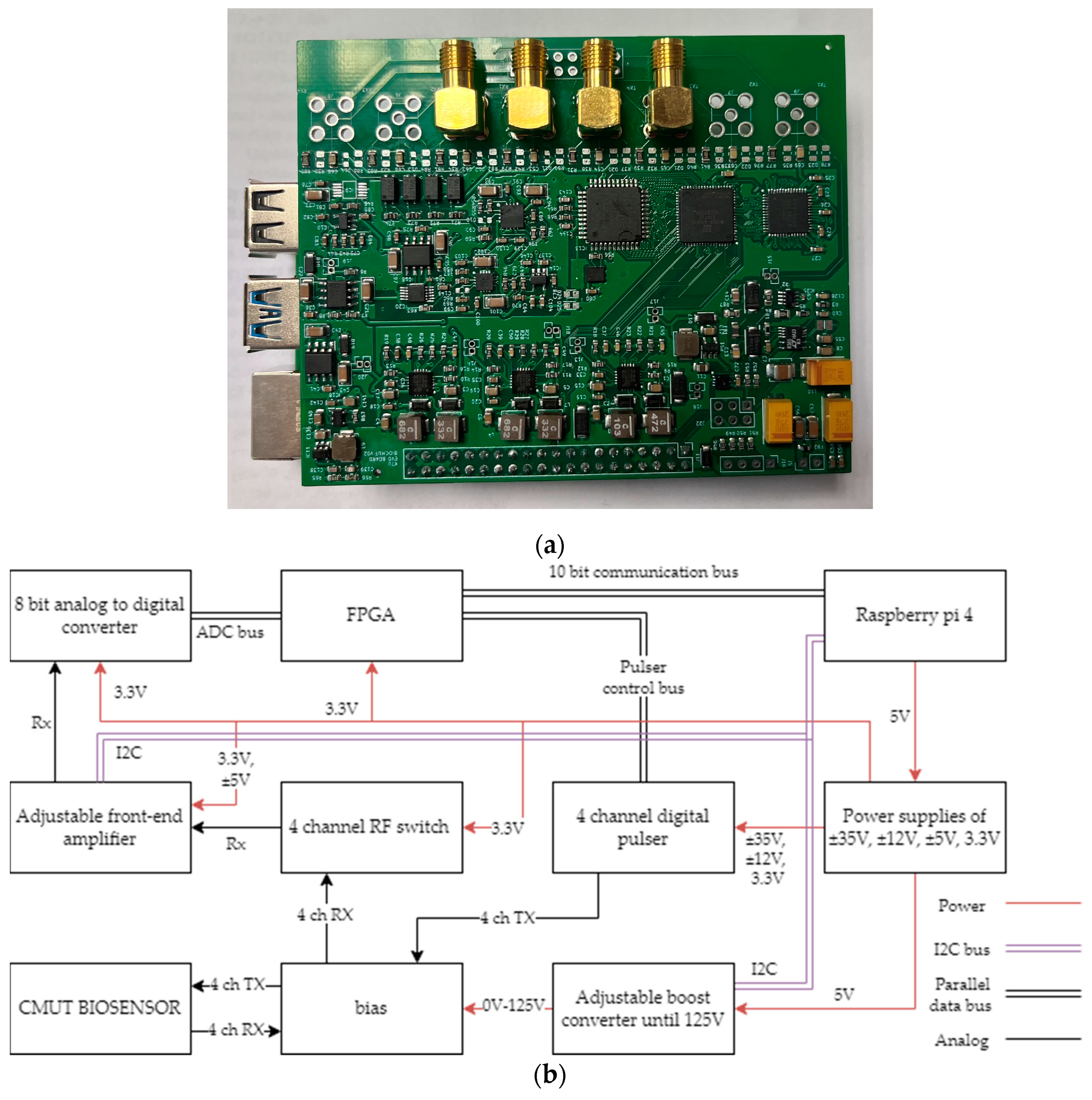
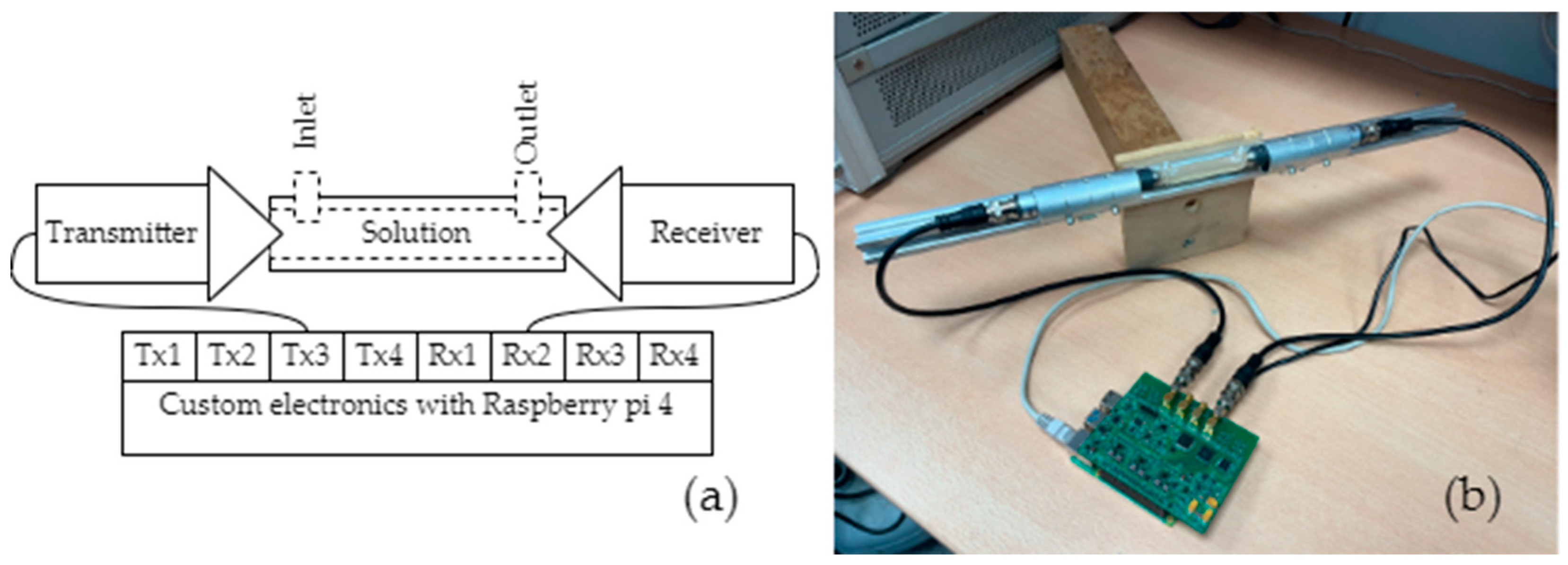
2.1. The Concept and Structure of the Single PCB TOF Electronics
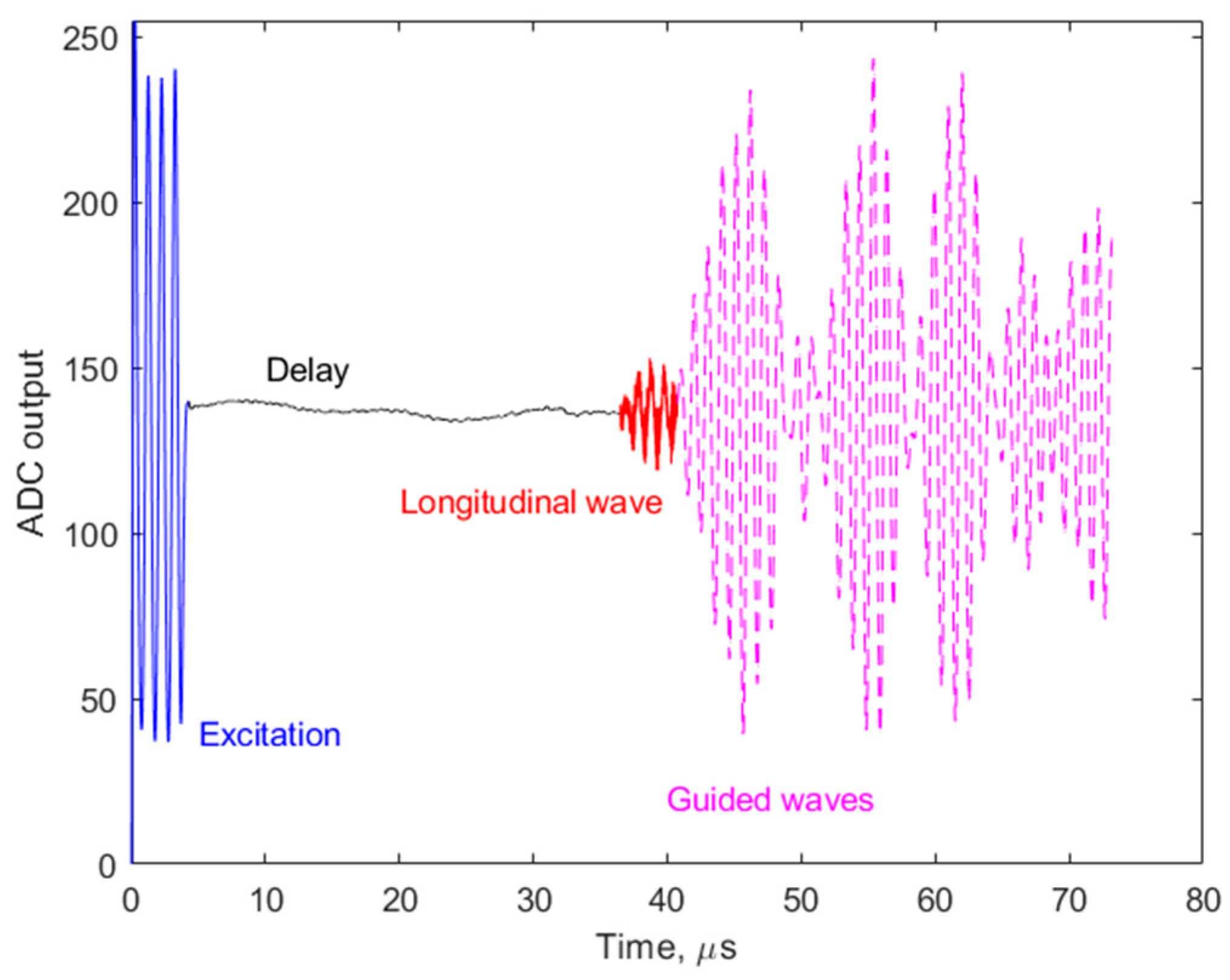
2.2. Signal Processing and Analysis
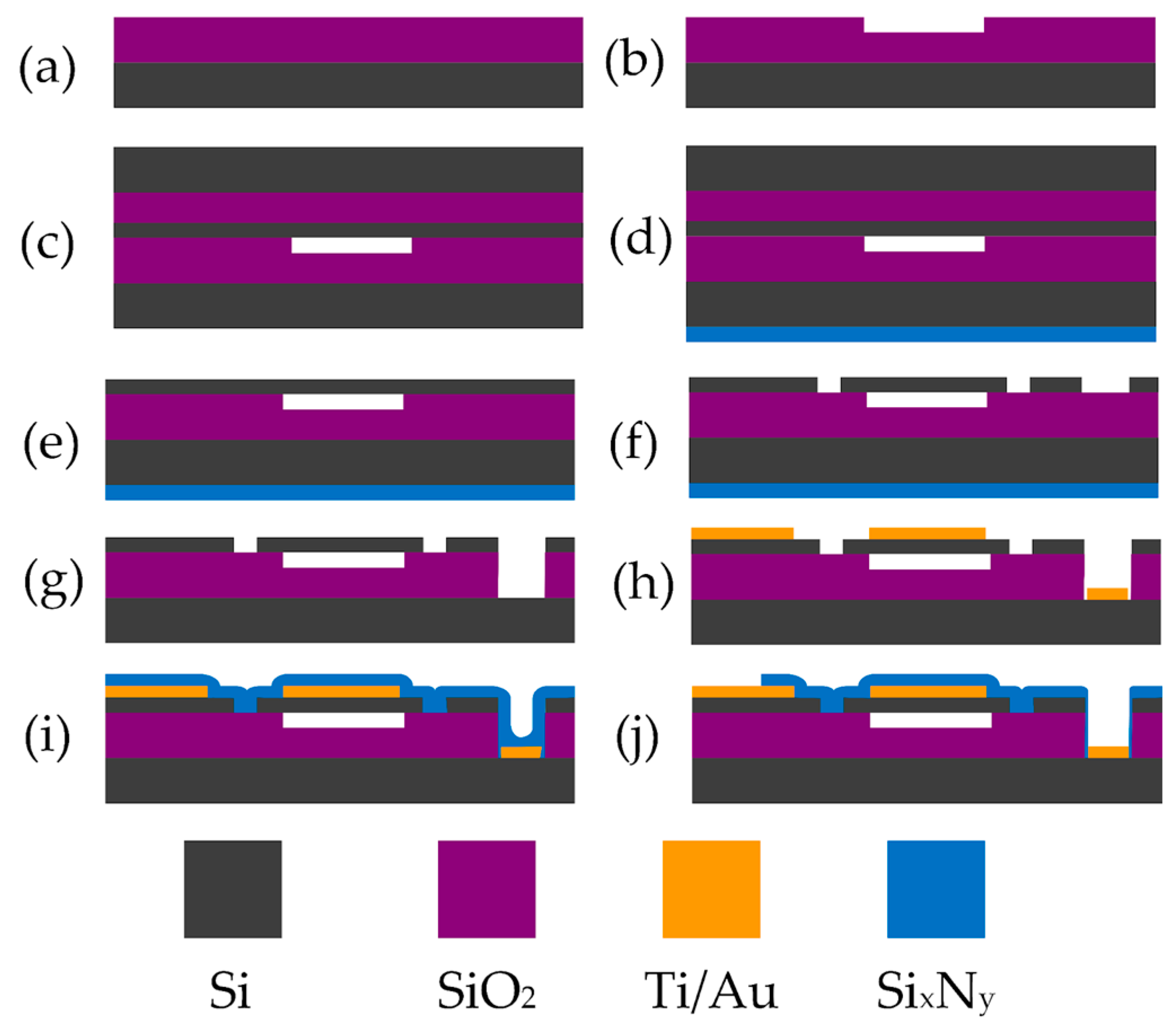
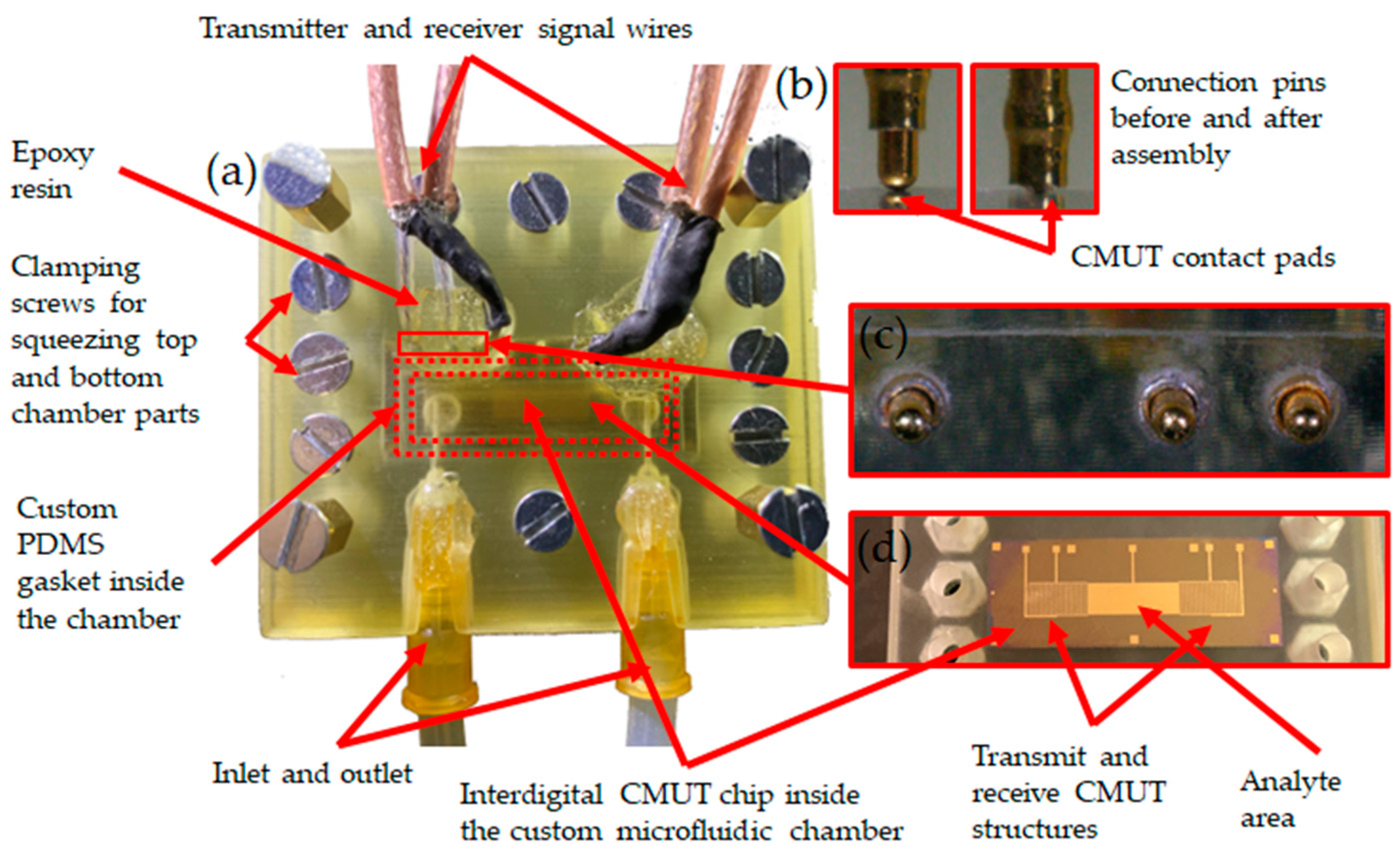
2.3. CMUT-Based TOF Measurement Channel
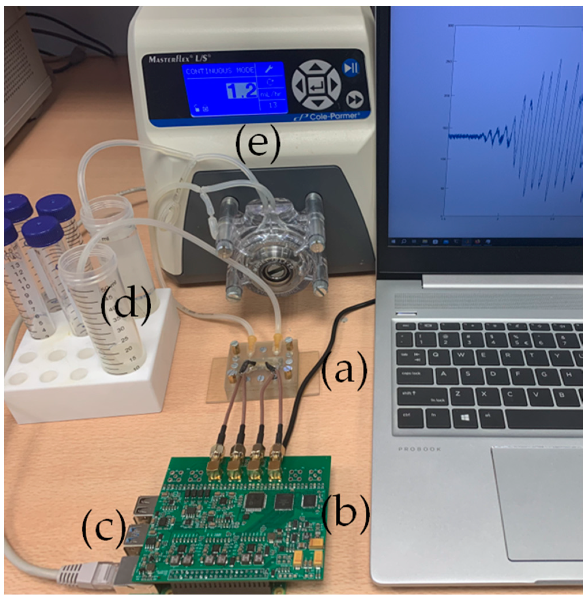
2.4. Interfacial Acoustic Wave Measurement Setup
2.5. Au NPs and Oligonucleotides
2.6. SAW Change by Au NP Surface Binding through DNA Oligonucleotide Interaction
2.7. The Bulk Acoustic Wave Experiment
3. Results
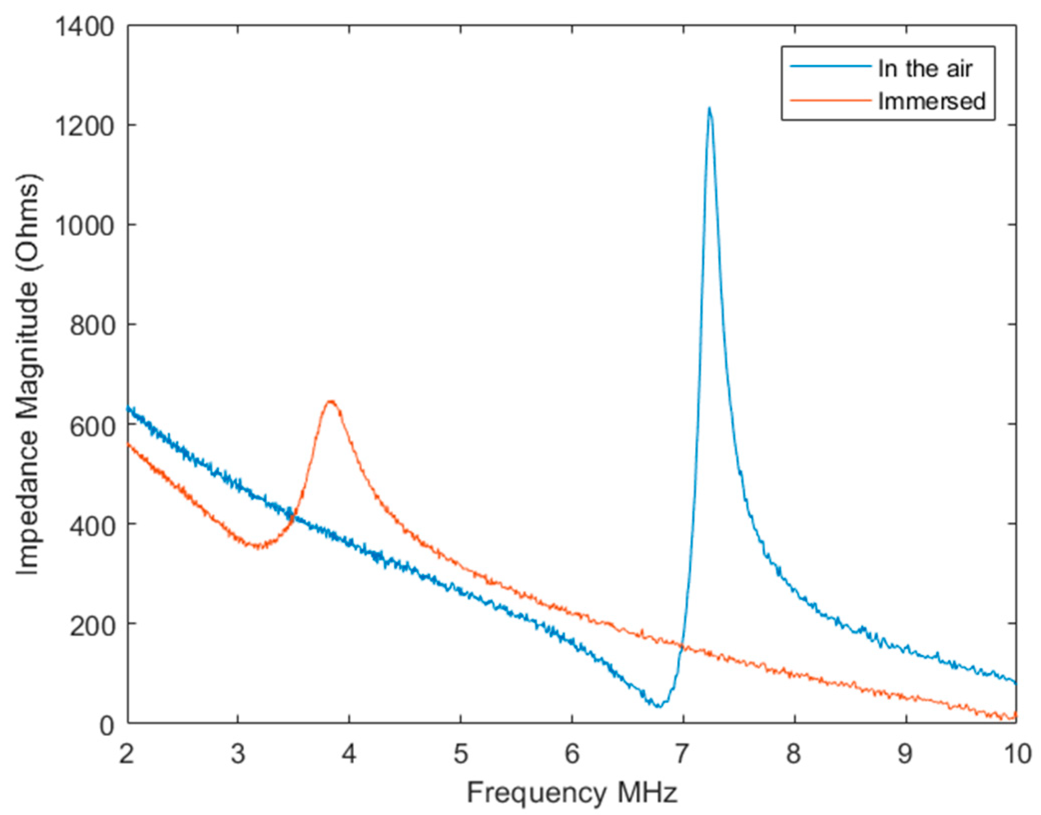
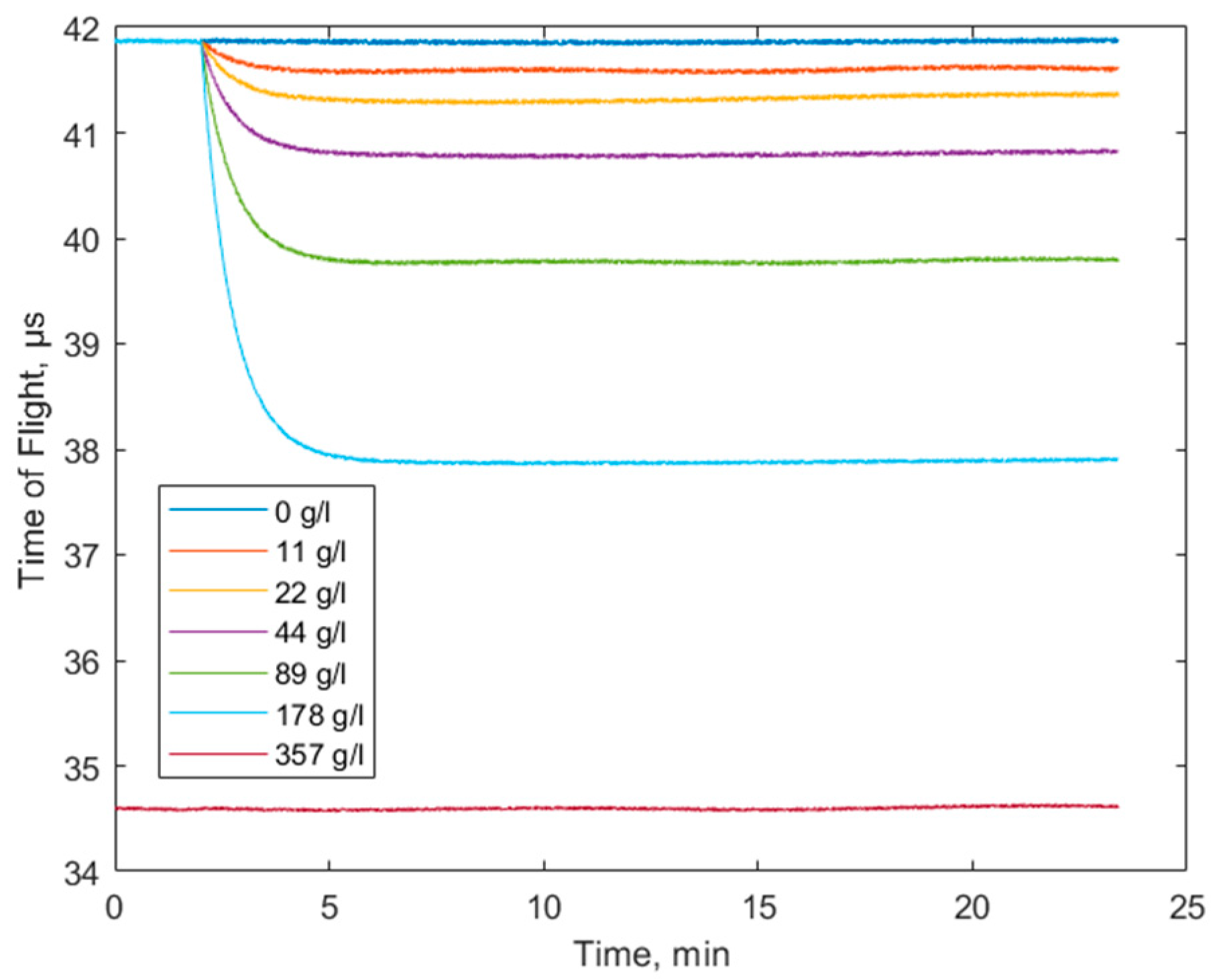
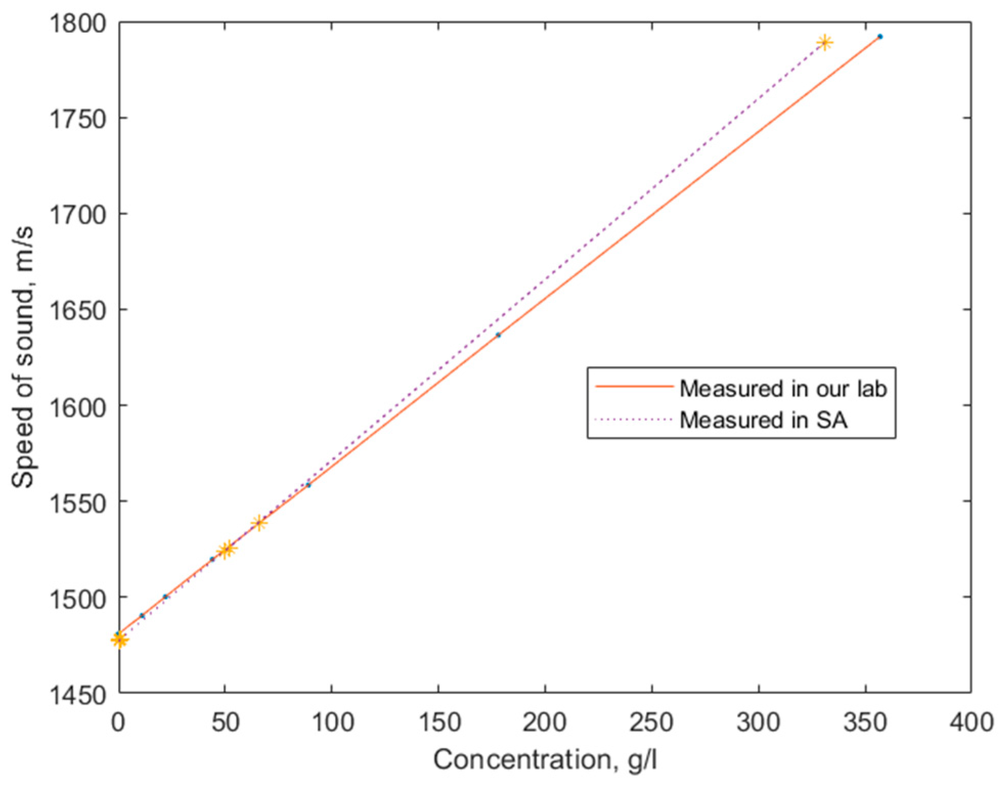
3.1. The Bulk Acoustic Wave Experiments
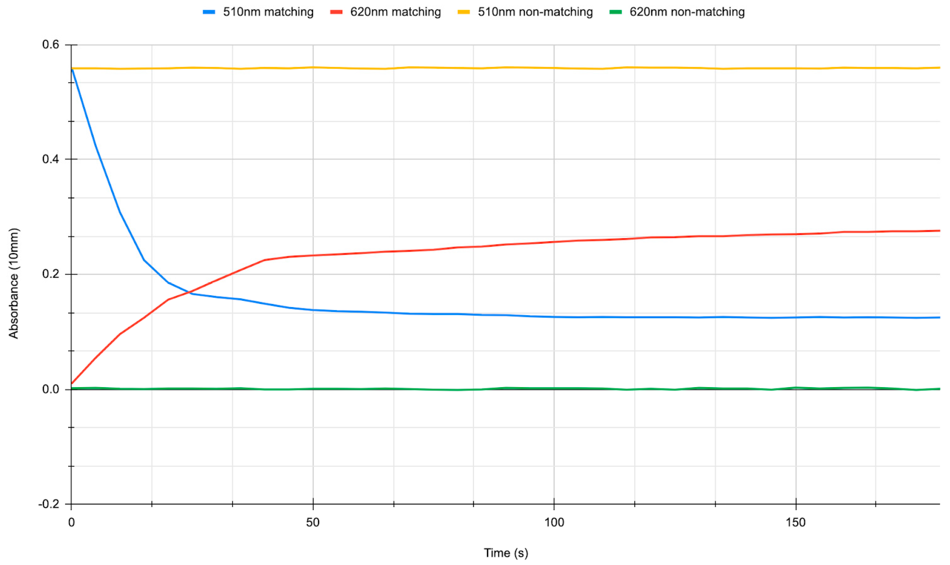
3.2. DNA Oligonucleotide Interactions
4. Discussion and Conclusions
Author Contributions
Funding
Institutional Review Board Statement
Informed Consent Statement
Data Availability Statement
Acknowledgments
Conflicts of Interest
References
- Bühling, B.; Küttenbaum, S.; Maack, S.; Strangfeld, C. Development of an Accurate and Robust Air-Coupled Ultrasonic Time-of-Flight Measurement Technique. Sensors 2022, 22, 2135. [Google Scholar] [CrossRef]
- Wang, X.F.; Tang, Z.A. A Novel Method for Digital Ultrasonic Time-of-Flight Measurement. Rev. Sci. Instrum. 2010, 81, 105112. [Google Scholar] [CrossRef] [PubMed]
- Marioli, D.; Narduzzi, C.; Offelli, C.; Petri, D.; Sardini, E.; Taroni, A. Digital Time-of-Flight Measurement for Ultrasonic Sensors. IEEE Trans. Instrum. Meas. 1992, 41, 93–97. [Google Scholar] [CrossRef]
- Why Use Time-Of-Flight for Distance Measurement? IEEE Spectrum. Available online: https://spectrum.ieee.org/why-use-timeofflight-for-distance-measurement (accessed on 18 January 2024).
- Fundamentals of Distance Measurement and Gesture Recognition Using ToF Sensors. Available online: https://www.digikey.com/en/articles/fundamentals-distance-measurement-gesture-recognition-tof-sensors (accessed on 18 January 2024).
- Lynnworth, L.C.; Liu, Y. Ultrasonic Flowmeters: Half-Century Progress Report, 1955–2005. Ultrasonics 2006, 44, e1371–e1378. [Google Scholar] [CrossRef] [PubMed]
- Li, C.-H.; Chang, Y.-C.; Hsiao, M.; Chan, M.-H. Ultrasound and Nanomedicine for Cancer-Targeted Drug Delivery: Screening, Cellular Mechanisms and Therapeutic Opportunities. Pharmaceutics 2022, 14, 1282. [Google Scholar] [CrossRef] [PubMed]
- Si-Chaib, M.O.; Djelouah, H.; Boutkedjirt, T. Propagation of Ultrasonic Waves in Materials under Bending Forces. NDT E Int. 2005, 38, 283–289. [Google Scholar] [CrossRef]
- Mandal, D.; Banerjee, S. Surface Acoustic Wave (SAW) Sensors: Physics, Materials, and Applications. Sensors 2022, 22, 820. [Google Scholar] [CrossRef] [PubMed]
- Wang, C.; Wang, C.; Jin, D.; Yu, Y.; Yang, F.; Zhang, Y.; Yao, Q.; Zhang, G.-J. AuNP-Amplified Surface Acoustic Wave Sensor for the Quantification of Exosomes. ACS Sens. 2020, 5, 362–369. [Google Scholar] [CrossRef] [PubMed]
- Zhao, J.; Wang, L.; Fu, D.; Zhao, D.; Wang, Y.; Yuan, Q.; Zhu, Y.; Yang, J.; Yang, F. Gold Nanoparticles Amplified Microcantilever Biosensor for Detecting Protein Biomarkers with High Sensitivity. Sens. Actuators Phys. 2021, 321, 112563. [Google Scholar] [CrossRef]
- Nair, M.P.; Teo, A.J.T.; Li, K.H.H. Acoustic Biosensors and Microfluidic Devices in the Decennium: Principles and Applications. Micromachines 2022, 13, 24. [Google Scholar] [CrossRef]
- Zida, S.I.; Lin, Y.-D.; Khung, Y.L. Current Trends on Surface Acoustic Wave Biosensors. Adv. Mater. Technol. 2021, 6, 2001018. [Google Scholar] [CrossRef]
- Chang, K.; Pi, Y.; Lu, W.; Wang, F.; Pan, F.; Li, F.; Jia, S.; Shi, J.; Deng, S.; Chen, M. Label-Free and High-Sensitive Detection of Human Breast Cancer Cells by Aptamer-Based Leaky Surface Acoustic Wave Biosensor Array. Biosens. Bioelectron. 2014, 60, 318–324. [Google Scholar] [CrossRef] [PubMed]
- Bharati, M.; Rana, L.; Gupta, R.; Sharma, A.; Jha, P.K.; Tomar, M. Realization of a DNA Biosensor Using Inverted Lamb Wave MEMS Resonator Based on ZnO/SiO2/Si/ZnO Membrane. Anal. Chim. Acta 2023, 1249, 340929. [Google Scholar] [CrossRef]
- Voiculescu, I.; Nordin, A.N. Acoustic Wave Based MEMS Devices for Biosensing Applications. Biosens. Bioelectron. 2012, 33, 1–9. [Google Scholar] [CrossRef]
- Timurdogan, E.; Alaca, B.E.; Kavakli, I.H.; Urey, H. MEMS Biosensor for Detection of Hepatitis A and C Viruses in Serum. Biosens. Bioelectron. 2011, 28, 189–194. [Google Scholar] [CrossRef] [PubMed]
- Erdil, K.; Akcan, Ö.G.; Gül, Ö.; Gökdel, Y.D. A Disposable MEMS Biosensor for Aflatoxin M1 Molecule Detection. Sens. Actuators Phys. 2022, 338, 113438. [Google Scholar] [CrossRef]
- Niranjan, A.; Gupta, P.; Rajoriya, M. Piezoelectric MEMS Micro-Cantilever Biosensor for Detection of SARS–CoV2. In Proceedings of the 2021 International Conference on Communication, Control and Information Sciences (ICCISc), Idukki, India, 16–18 June 2021; IEEE: New York, NY, USA, 2021; Volume 1, pp. 1–5. [Google Scholar]
- Rahimi, Z.; Yazdani, J.; Hatami, H.; Sumelka, W.; Baleanu, D.; Najafi, S. Determination of Hazardous Metal Ions in the Water with Resonant MEMS Biosensor Frequency Shift–Concept and Preliminary Theoretical Analysis. Bull. Pol. Acad. Sci. Tech. Sci. 2020, 68, 529–537. [Google Scholar] [CrossRef]
- Mehdipoor, M.; Badri Ghavifekr, H. Design and Analysis of a New MEMS Biosensor Based on Coupled Mechanical Resonators for Microfluidics Applications. Analog Integr. Circuits Signal Process. 2022, 111, 277–286. [Google Scholar] [CrossRef]
- Malavika, J.; Parameshwari, R.; Kalyani, D.; Prabha, P.L. MEMS Biosensor Design and Simulation for Diagnostic Purposes. In Proceedings of the Journal of Physics: Conference Series; IOP Publishing: Bristol, UK, 2022; Volume 2318, p. 012018. [Google Scholar]
- Thorat, B.; Jadhav, M. Design and Simulate MEMS Based Cantilever Biosensor for Detection of Tuberculosis. In Proceedings of the 2021 International Conference on Computational Intelligence and Computing Applications (ICCICA), Nagpur, India, 26–27 November 2021; pp. 1–4. [Google Scholar]
- Eidi, A. Design and Evaluation of an Implantable MEMS Based Biosensor for Blood Analysis and Real-Time Measurement. Microsyst. Technol. 2023, 29, 857–864. [Google Scholar] [CrossRef]
- Forouzanfar, S.; Alam, F.; Pala, N.; Wang, C. Highly Sensitive Label-Free Electrochemical Aptasensors Based on Photoresist Derived Carbon for Cancer Biomarker Detection. Biosens. Bioelectron. 2020, 170, 112598. [Google Scholar] [CrossRef]
- Forouzanfar, S.; Alam, F.; Khakpour, I.; Baboukani, A.R.; Pala, N.; Wang, C. Highly Sensitive Lactic Acid Biosensors Based on Photoresist Derived Carbon. IEEE Sens. J. 2020, 20, 8965–8972. [Google Scholar] [CrossRef]
- Zhou, L.; Kato, F.; Iijima, M.; Nonaka, T.; Kuroda, S.; Ogi, H. Mass-Fabrication Scheme of Highly Sensitive Wireless Electrodeless MEMS QCM Biosensor with Antennas on Inner Walls of Microchannel. Anal. Chem. 2023, 95, 5507–5513. [Google Scholar] [CrossRef]
- Zhou, L.; Kato, F.; Ogi, H. Sensitive Label-Free Immunoglobulin G Detection Using a MEMS Quartz Crystal Microbalance Biosensor with a 125 MHz Wireless Quartz Resonator. Jpn. J. Appl. Phys. 2021, 60, SDDB03. [Google Scholar] [CrossRef]
- Kurmendra; Kumar, R. MEMS Based Cantilever Biosensors for Cancer Detection Using Potential Bio-Markers Present in VOCs: A Survey. Microsyst. Technol. 2019, 25, 3253–3267. [Google Scholar] [CrossRef]
- McLean, J.; Degertekin, F.L. Directional Scholte Wave Generation and Detection Using Interdigital Capacitive Micromachined Ultrasonic Transducers. IEEE Trans. Ultrason. Ferroelectr. Freq. Control 2004, 51, 756–764. [Google Scholar] [CrossRef]
- Pelenis, D.; Barauskas, D.; Vanagas, G.; Dzikaras, M.; Viržonis, D. CMUT-Based Biosensor with Convolutional Neural Network Signal Processing. Ultrasonics 2019, 99, 105956. [Google Scholar] [CrossRef] [PubMed]
- Pelenis, D.; Vanagas, G.; Barauskas, D.; Dzikaras, M.; Mikolajūnas, M.; Viržonis, D. Acoustic Streaming Efficiency in a Microfluidic Biosensor with an Integrated CMUT. Micromachines 2023, 14, 1012. [Google Scholar] [CrossRef] [PubMed]
- Sapeliauskas, E.; Vanagas, G.; Barauskas, D.; Viržonis, D. Capacitive Micromachined Ultrasound Transducer as a Sensor in Microfluidic Environment. Sens. Lett. 2014, 12, 1597–1599. [Google Scholar] [CrossRef]
- Al-Nassar, Y.N.; Al-Jalal, A.M.; Khan, M.A.; Al-Kaabi, S.A. Functional Dependence of Ultrasonic Speed in Water on Salinity and Temperature. NDT. Net 2006, 11, 1–5. [Google Scholar]
- Kleis, S.J.; Sanchez, L.A. Dependence of Speed of Sound on Salinity and Temperature in Concentrated NaCl Solutions. Sol. Energy 1990, 45, 201–206. [Google Scholar] [CrossRef]
- Mujahid, A.; Afzal, A.; Dickert, F.L. An Overview of High Frequency Acoustic Sensors—QCMs, SAWs and FBARs—Chemical and Biochemical Applications. Sensors 2019, 19, 4395. [Google Scholar] [CrossRef]
- Hong, Y.; Lee, H.-J.; Kim, S.-G.; Kim, B.-H.; Yun, G.-H.; Yook, J.-G. A Label-Free Biosensing Platform Using a PLL Circuit and Biotin-Streptavidin Binding System. IEEE Trans. Biomed. Circuits Syst. 2015, 9, 345–352. [Google Scholar] [CrossRef]
- Huang, Y.; Das, P.K.; Bhethanabotla, V.R. Surface Acoustic Waves in Biosensing Applications. Sens. Actuators Rep. 2021, 3, 100041. [Google Scholar] [CrossRef]
- Rana, L.; Gupta, R.; Tomar, M.; Gupta, V. Highly Sensitive Love Wave Acoustic Biosensor for Uric Acid. Sens. Actuators B Chem. 2018, 261, 169–177. [Google Scholar] [CrossRef]
- Bharati, M.; Rana, L.; Gupta, R.; Sharma, A.; Jha, P.K.; Tomar, M. Simulation and Fabrication of Higher-Mode Lamb Wave Acoustic Devices for Sensing Applications. Phys. Status Solidi A 2023, 220, 2200760. [Google Scholar] [CrossRef]
- Liu, X.; Chen, X.; Yang, Z.; Xia, H.; Zhang, C.; Wei, X. Surface Acoustic Wave Based Microfluidic Devices for Biological Applications. Sens. Diagn. 2023, 2, 507–528. [Google Scholar] [CrossRef]


| Size | Name of the Parameter |
|---|---|
| 80 µm | Single membrane length |
| 30 µm | Single membrane width |
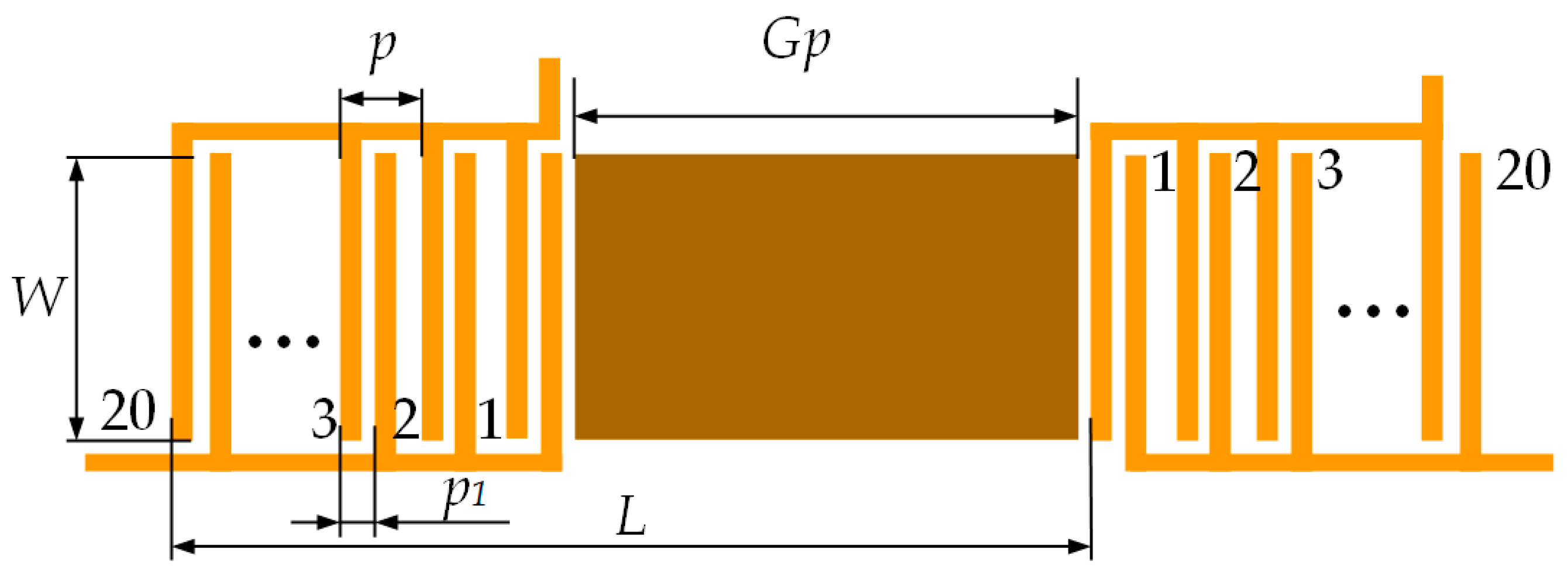
| 200 µm | IDT period (“pitch”), p |
| 50 µm | Distance between sub-fingers, p1 |
| 3 mm | Aperture width, W |
| 10 mm | Biological interaction site width, Gp |
| 13.7 mm | Distance between transmitter and receiver, L |
| 20 | Number of finger pairs |
| 7.5 MHz | Resonance frequency |
| Size | Name of the Parameter |
|---|---|
| 80 µm | Chamber width |
| 30 µm | Chamber length |
| 200 µm | Chamber height |
| 50 µm | Microchannel width |
| 3 mm | Microchannel length |
| 10 mm | Microchannel height |
Disclaimer/Publisher’s Note: The statements, opinions and data contained in all publications are solely those of the individual author(s) and contributor(s) and not of MDPI and/or the editor(s). MDPI and/or the editor(s) disclaim responsibility for any injury to people or property resulting from any ideas, methods, instructions or products referred to in the content. |
© 2024 by the authors. Licensee MDPI, Basel, Switzerland. This article is an open access article distributed under the terms and conditions of the Creative Commons Attribution (CC BY) license (https://creativecommons.org/licenses/by/4.0/).
Share and Cite
Pelenis, D.; Barauskas, D.; Dzikaras, M.; Viržonis, D. Four-Channel Ultrasonic Sensor for Bulk Liquid and Biochemical Surface Interrogation. Biosensors 2024, 14, 66. https://doi.org/10.3390/bios14020066
Pelenis D, Barauskas D, Dzikaras M, Viržonis D. Four-Channel Ultrasonic Sensor for Bulk Liquid and Biochemical Surface Interrogation. Biosensors. 2024; 14(2):66. https://doi.org/10.3390/bios14020066
Chicago/Turabian StylePelenis, Donatas, Dovydas Barauskas, Mindaugas Dzikaras, and Darius Viržonis. 2024. "Four-Channel Ultrasonic Sensor for Bulk Liquid and Biochemical Surface Interrogation" Biosensors 14, no. 2: 66. https://doi.org/10.3390/bios14020066
APA StylePelenis, D., Barauskas, D., Dzikaras, M., & Viržonis, D. (2024). Four-Channel Ultrasonic Sensor for Bulk Liquid and Biochemical Surface Interrogation. Biosensors, 14(2), 66. https://doi.org/10.3390/bios14020066