Abstract
The yellow rust of wheat (caused by Puccinia striiformis f. sp. tritici) is a devastating fungal infection that is responsible for significant wheat yield losses. The main challenge with the detection of this disease is that it can only be visually detected on the leaf surface between 7 and 10 days after infection, and by this point, counter measures such as the use of fungicides are generally less effective. The hypothesis of this study is to develop and use a compact electrochemical-based biosensor for the early detection of P. striiformis, thus enabling fast countermeasures to be taken. The biosensor that was developed consists of three layers. The first layer mimics the wheat leaf surface morphology. The second layer consists of a sucrose/agar mixture that acts as a substrate and contains a wheat-derived terpene volatile organic compound that stimulates the germination and growth of the spores of the yellow rust pathogen P. s. f. sp. tritici. The third layer consists of a nonenzymatic glucose sensor that produces a signal once invertase is produced by P. striiformis, which comes into contact with the second layer, thereby converting sucrose to glucose. The results show the proof that this innovative biosensor can enable the detection of yellow rust spores in 72 h.
1. Introduction
To accommodate for the rapidly increasing global population, it is estimated that global food production would need to increase by 70% to avoid a food crisis occurring [1,2,3,4,5].
Wheat (Triticum aestivum L.) is an important cereal crop and a staple source of food for approximately 40% of the world’s population [6]. In 2021, the global production of wheat was 778.6 million metric tons, with the European Union, China, and India being the three largest producers of it [7]. Due to the importance of this crop, wheat yield losses present a major problem for global food security [8,9].
Wheat yellow rust fungi (P. s. f. sp. tritici) is a fungal, biotrophic pathogen. Yellow rust can affect the grain quality, thereby reducing the protein content, as well as reducing the yield [10,11]. As an air-borne pathogen, the spores can be transported considerable distances via the wind, and they can also be carried on animals and human clothing [12,13]. Yellow rust is found predominantly in temperate and maritime environments, and its optimal temperature for infection and growth ranges between 7 and 22 °C [14,15].
Current strategies for yellow rust management are based on the use of genetically resistant wheat varieties and fungicide applications as part of an Integrated Pest Management scheme [16,17]. However, this contributes to the presence of pesticide-resistant fungal strains [18,19]. In addition, the timing of the fungicide application is critical for the treatments to be effective
P. s. f. sp. tritici spore germination can be seen within three hours of spores being deposited onto the leaf surface (Figure 1). The spore absorbs the free moisture on the leaf surface, thus producing a germ tube. The cytoplasm within the spore moves into the growing germ tube as it orientates itself to be perpendicular to the epidermal cells of the leaf surface until it reaches a stomata [20,21,22,23]. Between 6–8 h after the inoculation, the germ tube grows between the guard cells of a stomata and by 8–12 h, a substomatal vesicle is formed inside of the stomatal cavity. Primary infection hyphae develop on the substomatal vesicle after 12–18 h [23,24]. A number of studies have suggested that P. s. f. sp. tritici produces its own invertase as it is required to aid the nutrition uptake of the pathogen by converting sucrose to glucose and fructose [25,26]. Yellow rust also leads to an increase in the number of the reactive oxygen species that are in the infected plants, hence reducing the plant’s overall photosynthetic efficiency, thereby leading to yield loss [27].
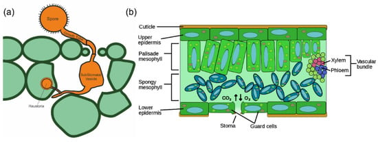
Figure 1.
(a) Schematic representation of early infection structures of Puccinia striiformis. The spore germ tube enters the leaf through the stomata, thereby forming a substomatal vesicle from which infection-hyphae develop. Once the hyphae contact the mesophyll cell, a haustoria is formed inside the plant cell. (b) Transverse section of a plant leaf showing the different layers of the leaf.
The volatile organic compounds (VOC) are the metabolites that are produced by the plants that are released into the air. Plants use volatiles to protect themselves from abiotic and biotic stresses, and to supply information (or disinformation) to mutualists (ex: pollen carriers) and competitors [28,29]. The VOCs act as information transferors, resolving many problems that are faced by the plant’s lack of mobility. The VOC blends are dominated by four biosynthetic classes, terpenoids, fatty acids, amino acids, and compounds with aromatic rings (Figure 2). Several lipophilic volatiles are released from the membranes of the plant’s epidermal tissues. However, in the leaves and stems, the VOCs are released through the stomata, therefore the opening and closing of the stomata influences the volatiles’ release [28,29].
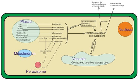
Figure 2.
Most plant volatiles are derived from four biosynthetic classes: aromatics, fatty acid, terpenoids, and amino acids. Volatiles are produced from fatty acids via oxidative cleavage. Several of these products are modified to be more lipophilic prior to release through the masking or removing of hydrophilic functional groups through methylation or reduction reactions. Figure modified from [28].
A major challenge that is related to yellow rust is that the disease’s symptoms can only be visually detected 7 to 10 days after the infection. However, at this stage, the use of preventative fungicides is largely redundant as the production of large numbers of spores are seen 14 days after the infection which spread the disease through the field. This raises the need for an early pathogen detection system that would enable farmers to apply preventative fungicide treatments well in advance of the infection and disease establishment stages.
Hyperspectral imaging technologies are used for plant disease detection procedures, and recently they have been increasingly investigated for yellow rust detection [30,31,32]. Spectral sensors measure the light that is reflected from the plant’s surface [33]. As the disease develops, the light spectrum shifts, thereby enabling the disease’s detection [34,35,36]. These systems use machine learning processes, and to operate, they properly require the crops to be monitored for a few seasons to collect enough data to enable that a subsequent accurate detection is made as well as to detect the symptomatic responses of the plants. Thus, their immediate deployment and use is not possible. Moreover, these systems are prone to errors due to different angles of sunlight being reflected from the plant’s surface.
Biosensors are used for agricultural and environmental monitoring applications to detect various pathogens and other environmental contaminants [37,38]. Due to their relatively high detection rate and short response time, the frequency of the use of biosensors is increasing [39,40]. However, the main challenges that is faced by current biosensors lie in their sensor performance, sampling, scaling up, and detection in open areas [37,38]. Roy et al. [41] fabricated an array of whole-cell biosensors to detect the aromatic pollutants such as benzene, phenols, and toluene, which are carcinogenic compounds that are found in polluted water sources. The sensor was able to detect the inert pollutants without any functional groups. However, this biosensor was temperature sensitive, which limited its operation in the field. Moreover, the authors did not provide any details regarding the detection time. Shi et al. [42] designed a colorimetric nanobiosensor to detect acetamiprid in soil. The sensor exhibited a high stability, sensitivity, and selectivity. However, it required that the soil samples be air-dried and that the ground be passed through a 1 mm sieve, then oven dried at 35 °C for 48 h. Then, dichloromethane (DCM) was added to the sample and filtered, and finally it was mixed with the sensing solution [42].
Advances in the field of nanomaterials have produced a promising nanoparticle-based biosensors. Nanoparticles are used for both enzymatic and non-enzymatic glucose biosensors, incorporating nanomaterials (e.g., noble and transition metal nanoparticles, CNTs, graphene, and nanostructured metal oxides) to amplify the electron transfer rate, thereby improving the biosensor’s performance in terms of its selectivity and sensitivity [43,44].
The research that is presented here proposes an innovative, pre-symptomatic yellow rust detection system that consists of a three-layered biosensor, thus representing the first biosensor for yellow rust detection. The proposed biosensor has a low cost and it is accessible, in-field detection device for yellow rust. The material and fabrication costs have been kept below £5 per unit. The production of the sensor is a simple and direct method that used commonly found apparatus and has an average lead time of 15 min. The operational rationale of the proposed modular sensor is shown in Figure 3. The target analyte (spores of P. s. f. sp. tritici) lands on the artificial surface of the sensor (first layer). This layer mimics the wheat leaf morphology with parallel venation and artificial stomatal openings. Following the spore’s landing, germination takes place. The spores produce germ tubes that grow through the artificial stomatal opening towards the second layer, which consists of a sucrose/agar mixture that acts as a feeding media, and a plant VOC that acts as a growth-enhancing stimulant [29]. Invertase is produced by the germinated spores, thus breaking down the sucrose into glucose. The third layer is a nonenzymatic glucose sensor that detects the glucose [26], generating an electrochemical response which can be detected using cyclic voltammetry (CV), thereby signalling the presence of the target pathogen.
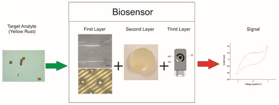
Figure 3.
Operational rationale of proposed yellow rust biosensor. The signal can be obtained directly as a CV curve indicating the presence of glucose and therefore yellow rust.
2. Materials and Methods
2.1. Materials
Polyethylene terephthalate glycol (PETG) was purchased from RS components (Northants, UK). Micrux single thick screen-printed electrodes were purchased from Alvatek,(WE: Carbon/RE: Silver/CE: Carbon) (Hampshire, UK). Gold (III) chloride (AuCl3), nickel acetate tetrahydrate (Ni (OCOCH3)2 · 4H2O), N, N-dimethylformamide (DMF), activated carbon (AC), dichloromethane (DCM), ethanol, agar A4550, dimethylamine borane (DMAB), terpene, and sucrose were purchased from Merck (Dorset, UK).
2.2. Sensor Fabrication
The sensor biomimetic surface was fabricated through a casting process. A mould was previously designed using Solidworks (Dassault systems, Waltham, MA, USA), mimicking the wheat leaf surface (Figure 4). Formlabs Form3 (Formlabs, Somerville, MA, USA) was used to produce the mould with a resolution of 100 µm (Table 1). After printing the mould (Figure 5), a PETG solution was prepared by dissolving PETG in DCM 1:10 ratio (w/v). The PETG solution (0.005 pas) was then poured into the mould and left to dry for two hours. The produced layer was then peeled off.
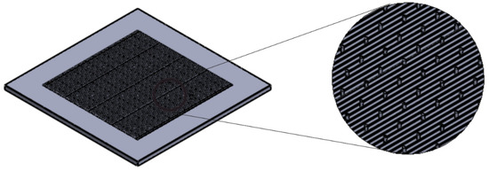
Figure 4.
3D model of the designed biomimetic leaf surface.

Table 1.
Printing parameters.
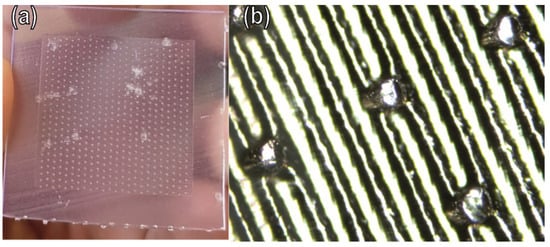
Figure 5.
(a) Printed mould; (b) optical microscope image presenting the details of the printed model.
The second layer was fabricated by mixing Agar A4550 and sucrose in a 1:4 (w/w) ratio. Briefly, 0.1 g of agar and 0.4 g of sucrose were added to 20 mL of de-ionised water and stirred until a homogenous solution was obtained. The solution was heated up to 100 °C using a hot plate, cooled down to 35 °C to allow for gelation, and left to cool down to room temperature. Finally, a terpene VOC was injected into this agar gel.
The third layer consists of an Au-Ni/AC-modified screen-printed electrode. An equal amount of gold (III) chloride and nickel (II) acetate (0.25 mmol) was dissolved in 15 mL of ethanol, which was followed by the addition of 2.5 mmol of activated carbon. Activated carbon was used to increase the surface area to amplify the sensing response by having a larger area for interaction between the glucose and the nanoparticles. The solution was stirred until a homogenous mixture was obtained and refluxed for two hours at 90 °C. Then, dimethylamine borane (DMAB) was added (1 mg), and the mixture was refluxed again for an additional hour. DMAB was used for the reflux, and this is used for activation of the gold-nickel-activated carbon nanocomposite. Finally, the obtained mixture was dried to obtain the sensing gold-nickel-activated carbon nanocomposite (Au-Ni/AC). The screen-printed electrode was modified using drop casting. Briefly, 1:10 (w/v) of Au-Ni/AC was added to DMF. The solution was sonicated for 30 min ensuring that the material was completely dispersed. Finally, 10 µL of the solution was drop casted on the SPE working electrode (WE) (Figure 6). The SPE was left to dry for 24 h in the fume cupboard.
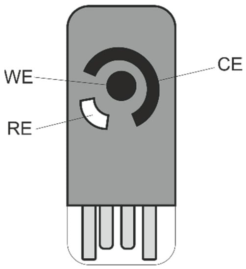
Figure 6.
Schematic of the screen-printed electrode. WE: working electrode, CE: counter electrode, RE: reference electrode.
2.3. Inoculation
The bioactivity of the top layer of the biosensor was tested by inoculating with P. s. f. sp. tritici spores. Briefly, the surface was placed in the middle of a stainless-steel pipe that was covered by an aluminium sheet at the top and bottom (spore inoculation tower). A small hole at the side of the steel pipe was used to blow the spores into the pipe, with the spores settling onto the biosensor surface by gravity. The surfaces were left in the steel pipe for 15 to 30 min to ensure that all spores had settled to the bottom of the pipe. The inoculated surfaces were then inspected under a light microscope to confirm that the spores had landed on the surface. The inoculated biosensors were placed in an incubator at 7 °C in total darkness at 60%humidity for 24 h.
2.4. Morphology
P. s. f. sp. tritici spore growth was investigated using optical microscopy (Keyence VHX-5000; Keyence, Milton Keynes, UK). The images were obtained using a top light at two magnifications (×5 and ×10). The light exposure was 100%.
The morphology of both the first and third layers of the biosensor was characterised using the scanning electron microscopy (SEM) Tescan Mira3 system (Tescan, Kohoutovice, Czech Republic). The first layer was platinum coated prior to imaging using the 108-auto sputter coater (Cressington scientific instruments, Watford, UK). Imaging was performed using 20 KV acceleration voltage. Images were analysed using ImageJ (Laboratory for Optical and Computational Instrumentation, University of Wisconsin, Madison, WI, USA) to determine the pore size of the first layer and the gold-nickel dispersion on the surface of the third layer. The morphology of the third layer was further studied using atomic force microscopy (AFM) nanosurf FlexAFM system (Nanosurf AG, Liestal, Switzerland). The structure was assessed using X-ray diffraction (XRD) which was carried out using X’Pert Pro X’celerator (Malvern Panalytical, Malvern, UK). Spectra were collected in the range of 2θ between 20° and 100°.
2.5. Electrochemical Measurements
The electrochemical behaviour of the sensor was assessed through cyclic voltammetry, and chronoamperometry using the µAUTOLABIII/FRA2 potentiostat (Metrohm Autolab, Utrecht, The Netherlands), and measurements were conducted at room temperature using a lab-made electrochemical cell. Cyclic voltammetry was performed using a potential range −1.0 V to 1.0 V with a scan rate of 100 mVs−1 to monitor the onset-potential of the prepared sensors towards the glucose catalytic oxidation from glucose to gluconolactone. Chronoamperometry was performed using a potential of 0.66 V over a time of 600 s.
Electrochemical Impedance Spectroscopy (EIS) was used to evaluate the performance of the sensor using the µAUTOLABIII/FRA2 potentiostat (Metrohm Autolab, Utrecht, The Netherlands). This technique applied an alternate current (AC) rather than a continuous one (DC). To obtain the optimal frequency, a frequency range of 100 kHz–0.1 Hz was used for impedance spectroscopic measurements. The amplitude of oscillation (AC) was set to 10 mVRMS. The optimal working potential was set to +0.66 V for measurements of glucose, respectively.
3. Results and Discussion
3.1. Morphological Characterisation
Read et al. [45] investigated the growth of Puccinia graminis f. sp. tritici (wheat stem rust) and Puccinia hordei (barley brown rust) on the artificial surfaces that mimic the leaf morphology using polyesters. As P. striiformis is related to P.g. f. sp. tritici and P. hordei, it was assumed that P. striiformis would be able to grow on similar materials. Therefore, it was decided that they would use a material with the same backbone, polyethylene terephthalate glycol (PETG), and that they would fabricate the biosensor by 3D printing. PETG is a bioactive and biocompatible material [46].The moulded PETG layer (first layer of the biosensor) was designed to mimic the wheat leaf surface morphology, presenting parallel grooves and stomatal holes (Figure 7a). The parallel grooves had a size of 200 µm, and the stomatal holes an average size of 50 µm, with openings with an average size of 15 µm. The SEM images of the Au-Ni/AC modified screen-printed electrode captured two distinct regions (Figure 7b). The upper region exhibited a cotton-like nanostructure, while the bottom region showed a brain-like nano porous structure with small grains and channels. From the SEM images it was also possible to observe the presence of gold and nickel (light white) and activated carbon (black). The atomic force microscopy (AFM) results of the third layer (Figure 7c) showed that there was the presence of round cap columns that were composed of several grains ranging between 40 nm to 1 µm. Channels with an average width of 5 µm were formed around the columns, thus allowing the glucose to pass through them.
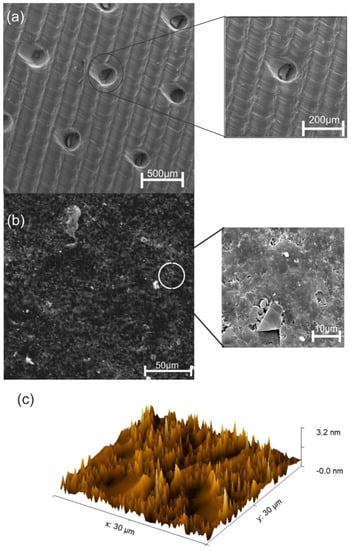
Figure 7.
(a) SEM image of the casted biomimetic PETG layer. The created parallel venation mimics the wheat leaf with a width of 200 µm. The detailed, zoomed SEM image shows a stomatal hole with a diameter of 50 µm with an opening of 15 µm. (b) SEM images of the Au-Ni/AC modified screen-printed electrode, presenting two distinct regions. The zoomed-in SEM image clarifies the two regions where the carbon bed presents a nano-porous structure, thus allowing glucose to flow, and the top region, which is a cotton-like nanostructure consisting of Au-Ni particles. (c) AFM image of the Au-Ni/AC modified screen-printed electrode exhibiting cylindrical round cap columns with channels allowing glucose to pass through.
3.2. Electrochemical Behaviour of the Au-Ni/AC SPE
The electrochemical behaviour of the Au-Ni/AC SPE toward glucose oxidation was assessed to evaluate its potential for glucose sensing. Figure 8 presents the CV curve of the Au-Ni/AC SPE in the absence (blue) and presence (red) of 10mmol of glucose in 0.1 mol NaOH. The CV curves that were obtained from the sensor exhibit four oxidation peaks at −0.27 V (peak A), 0.22 V (peak B), 0.53 V (peak E), and 0.66 V (peak D), and one reduction peak at −0.04 V (peak C). Peaks A, B, and C correspond to the typical two-step Au-glucose oxidation process, whereas peak C represents the reduction step that occurs in order to regenerate the sensor active sites, despite the presence of Ni. The electrocatalytic mechanism of Au-Ni/AC for glucose is a multistep process [47]. The process is initiated when the glucose molecules are dehydrogenated and adsorbed onto the surface of the Au-Ni/AC particles, which is followed by an increase in the metal-OHads that increases the potential, hence mediating the catalytic oxidation of the intermediaries towards gluconolactone.
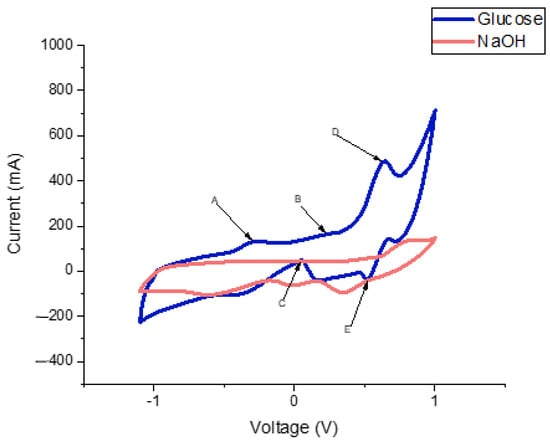
Figure 8.
CV curve of the Au-Ni/AC modified screen-printed electrode using NaOH as a buffer. The red curve corresponds to NaOH without glucose. The blue curve corresponds to NaOH in the presence of glucose. From the blue curve it is possible to observe the oxidation peaks at peak A (−0.27 V), peak B (0.22 V), peak E (0.53 V), and peak D (0.66 V), and a reduction peak at peak C (0.04 V).
Similar to glucose oxidation that occurs on pure gold surfaces [48,49], the glucose oxidation that occurs on the surface of the Au-Ni/AC SPE mainly depends on the quantity of the metal-OHads as well as on the premonolayer oxidation of the metal-producing metal-OHads. Peak A (Figure 8) can be linked to the glucose dehydrogenation-forming adsorbed intermediate products. The intermediate accumulation that is due to the limited number of metal-OHads sites is produced at a lower potential (−0.27 V), blocking the Au-Ni/AC SPE surface active sites, and hence, decreasing the current. Peak B at 0.22 V is attributed to the consecutive catalytic oxidation of the adsorbed intermediates due to the increased metal-OHads sites, while peak D corresponds to the formation of metal oxides. In the negative potential scan, there is a current increase at 0.04 V that is due to the reduction of surface metal oxides that have a more negative potential than 0.23 V, and the presence of enough metal-OHads sites for the glucose catalytic oxidation. A similar behaviour was observed by Gao’s group, using a different setup, where Au-Ni were used as a core and shell, respectively, and this showed an increase in the anodic current at a potential of 0.26 V [50].
Peaks D and E are also associated with the conversion between Ni(II) and Ni(III) as they share a CV behaviour that is similar to that of Ni-based electrodes [51]. The Ni reaction mechanism in the alkaline medium for glucose oxidation can be explained as follows:
Ni + 2OH− → Ni (OH)2 + 2e−
Ni (OH)2 + OH− → NiO (OH) + H2O + e−
NiO (OH) + glucose → glucolactone + Ni (OH)2
The sensor was then tested for its potential to perform glucose detection without a buffer to simplify the sensor. As it can be observed from the CV profiles (Figure 9), it is possible to differentiate between the different electrochemical responses of glucose and sucrose.
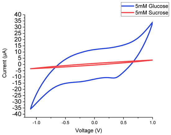
Figure 9.
CV curves without a buffer (NaOH). The blue curve represents the response to 5 mM glucose. The red curve represents the response to 5 mM sucrose.
The amperometric response of the Au-Ni/AC SPE was investigated at 0.66 V (Figure 10), which corresponds to the oxidation peak that was observed on the CV. The glucose was successively added into the 0.1 mM of NaOH at 24 s intervals for 20 steps. The sensor presented with an extremely fast and stable response.
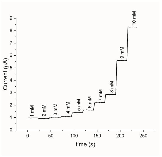
Figure 10.
Current–time responses at +0.66 V with an increasing glucose concentration.
The Au-Ni/AC SPE has been tested for its specific response by the successive addition of glucose onto the sensor that was dipped in NaOH. The chosen range was 1–10 mM as the target concentration for the detection of yellow rust was 5 mM as based on the designed second layer. The calibration curve (Figure 11) shows that there was an exponential increase in the peak generated current with the addition of glucose, which is in agreement with the trends that can be found in the literature [52,53].
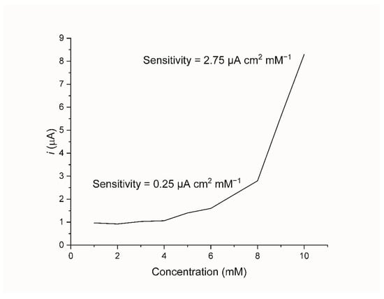
Figure 11.
Calibration curve of the current verses different glucose concentrations (1 to 10 mM).
It can be observed that there are two linear ranges between 1–8 mM and another between 8–10 mM. Based on these ranges, the two sensitivities have been calculated using a linear fit are 0.25 μA cm2 mM−1 and 2.75 μA cm2 mM−1, respectively. The limit of detection (LOD) has also been tested experimentally to find the lowest concentration that the sensor can detect which was found to be 0.05 μM. The performance of this biosensor is in line with other non-enzymatic nanoparticle-based glucose biosensors in terms of its sensitivity, linear ranges, and LOD. The reported sensitivities are between , while the linear ranges are between , and the LOD is 0.1–15 μM [54,55,56].
An electrochemical impedance spectroscopy was conducted to analyze the impedance changes on the modified electrode surfaces. In the EIS, the presence of a straight line represents that the diffusion limited the electrochemical process, which is the hypothesis of this paper [57]. Pletcher [58] suggests the electrocatalytic process implies that there is a key role for the adsorbed intermediates. Suggesting that the initial oxidation of the glucose was limited to the surface would result in a bulk oxidation which can be indicated by the linear behaviour that is presented in Figure 12.
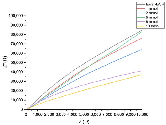
Figure 12.
Nyquist plots for Au-Ni/AC SPE in 0.1 M NaOH solution for 0–10 mM glucose concentration range.
The stability of the Au-Ni/AC SPE was tested by us performing cyclic voltammetry measurements before and after the amperometric analysis fifty times over, and these are shown in Figure 13. The results reveal that after a long period of electrolysis using the electrode, the current kept almost 100% of its initial amount, whilst the peak potential moved in a slightly positive direction by 0.6 V. The reproducibility and repeatability of the electrode were also determined by repeated testing, which was conducted for 1, 25, and 50 cycles in 5 mM glucose in 0.1 M NaOH. These results imply that the proposed electrode has a reproducible current as it was not contaminated by the oxidation products and the shift remained constant between the 1, 25, and 50 cycles.
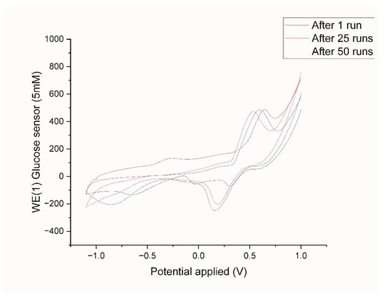
Figure 13.
CVs of Au-Ni/AC SPE after 1, 25, and 50 times of amperometric tests in 5 mM glucose in 0.1 M NaOH.
3.3. Nanoparticles Characterisation
The XRD patterns of the Au-Ni/AC nanoparticles are presented in Figure 14, which show that there were characteristic diffraction peaks at 2θ = 38.6°, 43.7°, 50.8°, 64.9°, 74.4°, 90.2°, and 95.4°. As previously reported, the peaks confirm the presence of the elements Au and Ni: 38.7° Au (111), 43.7° Au(200)-Ni(111)/AC(100)(101), 50.8° Ni(200), 64.9° Au(220), 74.4° Au(311)-Ni(220), 90.2° Ni(311), and 95.4° Au(400)-Ni(222). Furthermore, the shift in the peaks indicates that the Au-Ni/AC alloy was present on the sensor surface [59,60]. Furthermore, the average crystallite diameter (d) values that were calculated using Scherrer’s equation [Equation (1)] are ∼41.8 nm for the Au-Ni/AC nanoparticles using the full width at half maximum (FWHM) of the most intense peak at 43.7°. β is the FWHM value (radians), ‘λ’ is 1.5406 Å, which is the CuKα wavelength, and θ is the Bragg diffraction [61,62].
D = 0.9λ/(β cos θ)
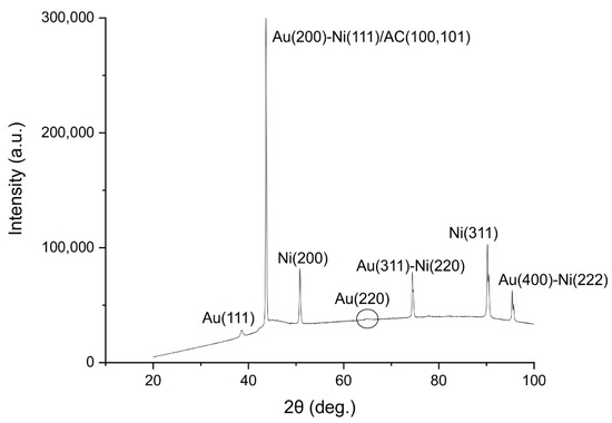
Figure 14.
Au-Ni/AC X-ray diffraction analysis. The peaks represent the different materials present on the surface of the electrode. Au(111) at 38.6°, Au(200)-Ni(111)/AC(100)(101) at 43.7°, Ni(200) at 50.8°, Au(311)-Ni(220) at 74.4°, Ni(311) at 90.2°, and Au(400)-Ni(222) at 95.4°.
3.4. Sensor Selectivity
The sensor was designed to operate at a temperature that ranged between 7 and 22 °C. A commercial screen-printed electrode was used to enable the connection to any CV machine, thereby allowing for its further integration in any system. Currently common wheat diseases include blotches, rusts, and head blight/scab [63]. Based on a genome analysis of all the agents that cause these diseases, it can be deduced that invertase production is a unique characteristic of P. s. f. sp. tritici spores, as is shown in Table 2 [26]. Hence, the sensor was designed to selectively detect the yellow rust pathogen.

Table 2.
List of common wheat diseases and their agents, indicating invertase production based on their genomic make-up.
3.5. Sensor Functionality
After printing the PETG sensor body, the agar/sucrose layer was placed inside of the sensor body and covered with the casted mimetic layer. The assembled sensor (Figure 15a) was inoculated with spores of the yellow rust pathogen P. s. f. sp. tritici and placed in a temperature-controlled incubator at 7 °C with a humidity of 60% in total darkness for 24 h [70]. P. s. f. sp. tritici spore germination on the surface of the biosensor was assessed using a light microscopy method (Figure 15b,c). The sensor was connected to the CV system to test for the presence of glucose, which returned negative results at 24 h after inoculation (Figure 15d). The sensor was placed back in the incubator at a cycle of 16 °C/ 16 h and 7 °C/8 h, and it was tested for the presence of glucose again at 48 and 72 h after inoculation. At 48 h, the response was negative, but at 72 h a positive glucose response was obtained (Figure 15e). The biosensor was tested three times, thus confirming the results. The growth of P. s. f. sp. tritici on the surface of the biosensor was further investigated using an SEM method (Figure 15f).
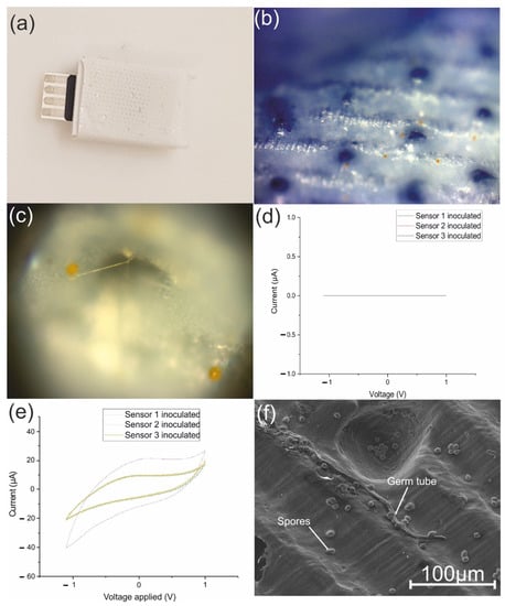
Figure 15.
(a) Biosensor assembly, (b) top surface of biosensor inoculated with P. s. f. sp. tritici spores, (c) underneath surface of the top layer of the biosensor showing a germinated P. s. f. sp. tritici spore, (d) CV curve obtained at 24 h, (e) CV curve obtained after 72 h, (f) SEM image of P. s. f. sp. tritici spores and a germ tube growth on the surface of the biosensor.
4. Conclusions
A novel, multi-layer electrochemical biosensor is proposed for the detection of the fungal pathogen that causes the plant disease yellow rust of wheat, i.e., P. s. f. sp. tritici. The first layer of this biosensor mimics the wheat leaf surface morphology by containing artificial stomata. The second layer consists of a sucrose/VOC/agar mixture that act as a substrate, while a wheat terpenoid VOC provides a stimulus for P. s. f. sp. tritici germination and the germ tube growth. The third layer is fabricated by casting cheap and affordable nanomaterials; the formed structure on the surface presents an innovative nonenzymatic sensor that detects the glucose that is released from sucrose due to fungal invertase activity.
The inoculation of the biosensor with the spores of P. s. f. sp. tritici resulted in a positive reaction 72 h after the spore inoculation. This biosensor would therefore enable the pre-symptomatic yellow rust detection using an electrochemical approach. This proof of concept provides a substantial improvement to the current state-of-the-art biosensors, thereby reducing the detection cost and time that it takes. Therefore, the biosensor is a promising solution for food security, and it can prevent substantial annual crop yield losses that are due to P. s. f. sp. Tritici.
The proposed multilayer biosensor consists of three modular layers that can be easily changed to allow for the detection of different pathogens. The modularity can be achieved by changing the morphology of the first layer to mimic the target crop, by changing the feeding media (second layer) that is tailored towards the target pathogen, with the third layer being changed to detect the target analyte to signal the presence of the targeted pathogen. Moreover, the biosensor can be integrated as a part of a wider sensing network using the internet of things (IOT), thereby leading to the development of an early disease detection and warning system. Further work is required to optimise the nonenzymatic glucose sensor that is presented in this work. Different ratios of Au to Ni need to be investigated as well as different methods of immobilising the nanomaterial on the working area of the screen-printed electrode. Finally, the general electrochemical properties of the proposed system needs to be investigated and studied providing an in depth understanding of the mechanisms of the sensor’s functions.
Author Contributions
Conceptualization, methodology, and software, M.H.H.; validation and formal analysis, M.H.H., A.M.O., E.D. and A.A.M.; investigation, M.H.H.; resources and data curation, all Authors; writing—original draft preparation, M.H.H.; writing—review and editing, M.H.H., A.M.O., C.B., P.J.B. and L.A.B.; visualization, M.H.H.; supervision, B.G. and P.J.B. All authors have read and agreed to the published version of the manuscript.
Funding
This work was supported by the Henry Royce Institute for Advanced Materials, funded through EPSRC grants EP/R00661X/1, EP/S019367/1, EP/P025021/1 and EP/P025498/1.
Institutional Review Board Statement
Not applicable.
Informed Consent Statement
Not applicable.
Data Availability Statement
Not applicable.
Conflicts of Interest
The authors declare no conflict of interest.
References
- Bindraban, P.; van Keulen, H.; Kuyvenhoven, A.; Rabbinge, R.; Uithol, P.W.J. Food Security at Different Scales: Demographic, Biophysical and Socio-Economic Considerations; AB-DLO: Wageningen, The Netherlands, 1999. [Google Scholar]
- Food and Agriculture Organization of the United Nations. The Future of Food and Agriculture Trends and Challenges; United Nations: Rome, Italy, 2017. [Google Scholar]
- Vos, R.; Bellù, L.G. Chapter 2—Global Trends and Challenges to Food and Agriculture into the 21st Century. In Sustainable Food and Agriculture; Campanhola, C., Pandey, S., Eds.; Academic Press: Cambridge, MA, USA, 2019; pp. 11–30. [Google Scholar]
- Calicioglu, O.; Flammini, A.; Bracco, S.; Bellù, L.; Sims, R. The Future Challenges of Food and Agriculture: An Integrated Analysis of Trends and Solutions. Sustainability 2019, 11, 222. [Google Scholar] [CrossRef]
- Serraj, R.; Pingali, P. Agriculture & Food Systems to 2050: Global Trends, Challenges and Opportunities; World Scientific: Singapore, 2018; Volume 2. [Google Scholar]
- Qian, L.; Li, F.; Liu, H.; Wang, L.; McCathy, B.; Jin, S. Rice vs. Wheat: Does staple food consumption pattern affect food waste in Chinese university canteens? Resour. Conserv. Recycl. 2022, 176, 105902. [Google Scholar] [CrossRef]
- Agriculture, F.U.D.O. Worldwide Production of Grain in 2021/22, by Type. 2022. Available online: https://www.statista.com/statistics/263977/world-grain-production-by-type/ (accessed on 3 March 2022).
- Grausgruber, H.; Ikeda, T.M.; Guzmán, C. FODMAPs in Wheat. In Wheat Quality for Improving Processing and Human Health; Springer: Berlin/Heidelberg, Germany, 2020; pp. 517–534. [Google Scholar]
- Singh, R.; Chintagunta, A.D.; Agarwal, D.K.; Kureel, R.; Kumar, S.J. Varietal replacement rate: Prospects and challenges for global food security. Glob. Food Secur. 2019, 25, 100324. [Google Scholar] [CrossRef]
- Murray, G.M.; Ellison, P.J.; Watson, A. Effects of Stripe Rust on the Wheat Plant. Australas. Plant Pathol. 1995, 24, 261–270. [Google Scholar] [CrossRef]
- Wang, M.; Chen, X. Stripe Rust Resistance. In Stripe Rust; Springer: Berlin/Heidelberg, Germany, 2017; pp. 353–558. [Google Scholar]
- Wan, A.M.; Chen, X.M.; He, Z. Wheat stripe rust in China. Aust. J. Agric. Res. 2007, 58, 605–619. [Google Scholar] [CrossRef]
- Solh, M.; Nazari, K.; Tadesse, W.; Wellings, C.R. The growing threat of stripe rust worldwide. In Proceedings of the Borlaug Global Rust Initiative (BGRI) conference, Beijing, China, 1–4 September 2012. [Google Scholar]
- Ali, S.; Gladieux, P.; Leconte, M.; Gautier, A.; Justesen, A.F.; Hovmøller, M.S.; Enjalbert, J.; de Vallavieille-Pope, C. Origin, Migration Routes and Worldwide Population Genetic Structure of the Wheat Yellow Rust Pathogen Puccinia striiformis f.sp. tritici. PLOS Pathog. 2014, 10, e1003903. [Google Scholar] [CrossRef]
- de Vallavieille-Pope, C.; Bahri, B.; Leconte, M.; Zurfluh, O.; Belaid, Y.; Maghrebi, E.; Huard, F.; Huber, L.; Lainey, M.; Bancal, M.O. Thermal generalist behaviour of invasive Puccinia striiformis f. sp. tritici strains under current and future climate conditions. Plant Pathol. 2018, 67, 1307–1320. [Google Scholar]
- Liu, R.; Lu, J.; Zhou, M.; Zheng, S.; Liu, Z.; Zhang, C.; Du, M.; Wang, M.; Li, Y.; Wu, Y.; et al. Developing stripe rust resistant wheat (Triticum aestivum L.) lines with gene pyramiding strategy and marker-assisted selection. Genet. Resour. Crop Evol. 2020, 67, 381–391. [Google Scholar] [CrossRef]
- Zeng, Q.; Zhao, J.; Wu, J.; Zhan, G.; Han, D.; Kang, Z. Wheat stripe rust and integration of sustainable control strategies in china. Front. Agric. Sci. Eng. 2022, 9, 37–51. [Google Scholar] [CrossRef]
- Mengesha, G.G. Management of yellow rust (Puccinia striiformis f. sp. tritici) and stem rust (Puccinia graminis f. sp tritici) of bread wheat through host resistance and fungicide application in Southern Ethiopia. Cogent Food Agric. 2020, 6, 1739493. [Google Scholar]
- El-Orabey, W.M.; Ashmawy, M.A.; Shahin, A.A.; Ahmed, M.I. Screening of CIMMYT Wheat Genotypes against Yellow Rust in Egypt. Int. J. Phytopathol. 2020, 9, 51–70. [Google Scholar] [CrossRef]
- Kang, Z. Ultrastructure of Plant Pathogenic Fungi; China Science and Technology Press: Beijing, China, 1996. [Google Scholar]
- Kang, Z.; Huang, L.; Li, J. Morphology of Plant Pathogenic Fungi Under Scanning Electron Microscope; Agriculture Press: Beijing, China, 1997. [Google Scholar]
- Chen, W.; Wellings, C.; Chen, X.; Kang, Z.; Liu, T. Wheat stripe (yellow) rust caused by Puccinia striiformis f. sp. tritici. Mol. Plant Pathol. 2014, 15, 433–446. [Google Scholar] [CrossRef] [PubMed]
- Wang, X.; Tang, C.; Zhang, G.; Li, Y.; Wang, C.; Liu, B.; Qu, Z.; Zhao, J.; Han, Q.; Huang, L.; et al. cDNA-AFLP analysis reveals differential gene expression in compatible interaction of wheat challenged with Puccinia striiformis f. sp. tritici. BMC Genom. 2009, 10, 289. [Google Scholar] [CrossRef]
- Mendgen, K.; Struck, T.; Voegele, R.T.; Hahn, M. Biotrophy and rust haustoria. Physiol. Mol. Plant Pathol. 2000, 56, 141–145. [Google Scholar] [CrossRef]
- Ruiz, E.; Ruffner, H.P. Immunodetection of Botrytis-specific Invertase in Infected Grapes. J. Phytopathol. 2002, 150, 76–85. [Google Scholar] [CrossRef]
- Chang, Q.; Liu, J.; Lin, X.; Hu, S.; Yang, Y.; Li, D.; Chen, L.; Huai, B.; Huang, L.; Voegele, R.T.; et al. A unique invertase is important for sugar absorption of an obligate biotrophic pathogen during infection. New Phytol. 2017, 215, 1548–1561. [Google Scholar] [CrossRef]
- Chen, Y.; Mao, H.; Wu, N.; Ma, J.; Yuan, M.; Zhang, Z.; Yuan, S.; Zhang, H. Effects of Stripe Rust Infection on the Levels of Redox Balance and Photosynthetic Capacities in Wheat. Int. J. Mol. Sci. 2019, 21, 268. [Google Scholar] [CrossRef]
- Baldwin, I.T. Plant volatiles. Curr. Biol. 2010, 20, R392–R397. [Google Scholar] [CrossRef]
- French, R.C. Stimulation of Uredospore Germination in Wheat Stem Rust by Terpenes and Related Compounds. Bot. Gaz. 1961, 122, 194–198. [Google Scholar] [CrossRef]
- Guo, A.T.; Huang, W.J.; Dong, Y.Y.; Ye, H.C.; Ma, H.Q.; Liu, B.; Wu, W.B.; Ren, Y.; Ruan, C.; Geng, Y. Wheat Yellow Rust Detection Using UAV-Based Hyperspectral Technology. Remote Sens. 2021, 13, 123. [Google Scholar] [CrossRef]
- Bohnenkamp, D.; Behmann, J.; Mahlein, A.-K. In-Field Detection of Yellow Rust in Wheat on the Ground Canopy and UAV Scale. Remote Sens. 2019, 11, 2495. [Google Scholar] [CrossRef]
- Su, J.; Liu, C.; Coombes, M.; Hu, X.; Wang, C.; Xu, X.; Li, Q.; Guo, L.; Chen, W.-H. Wheat yellow rust monitoring by learning from multispectral UAV aerial imagery. Comput. Electron. Agric. 2018, 155, 157–166. [Google Scholar] [CrossRef]
- West, J.S.; Bravo, C.; Oberti, R.; Lemaire, D.; Moshou, D.; McCartnet, H.A. The potential of optical canopy measurement for targeted control of field crop diseases. Annu. Rev. Phytopathol. 2003, 41, 593–614. [Google Scholar] [CrossRef] [PubMed]
- Wahabzada, M.; Mahlein, A.-K.; Bauckhage, C.; Steiner, U.; Oerke, E.-C.; Kersting, K. Plant Phenotyping using Probabilistic Topic Models: Uncovering the Hyperspectral Language of Plants. Sci. Rep. 2016, 6, 22482. [Google Scholar] [CrossRef] [PubMed]
- Whetton, R.L.; Hassall, K.L.; Waine, T.W.; Mouazen, A.M. Hyperspectral measurements of yellow rust and fusarium head blight in cereal crops: Part 1: Laboratory study. Biosyst. Eng. 2018, 166, 101–115. [Google Scholar] [CrossRef]
- Whetton, R.L.; Hassall, K.L.; Waine, T.W.; Mouazen, A.M. Hyperspectral measurements of yellow rust and fusarium head blight in cereal crops: Part 2: On-line field measurement. Biosyst. Eng. 2018, 166, 144–158. [Google Scholar] [CrossRef]
- Gupta, S.; Kakkar, V. Development of Environmental Biosensors for Detection, Monitoring, and Assessment. In Nanomaterials and Environmental Biotechnology; Springer: Berlin/Heidelberg, Germany, 2020; pp. 107–125. [Google Scholar]
- Adetunji, C.O.; Nwankwo, W.; Ukhurebor, K.E.; Olayinka, A.S.; Makinde, A.S. Application of Biosensor for the Identification of Various Pathogens and Pests Mitigating Against the Agricultural Production: Recent Advances. In Biosensors in Agriculture: Recent Trends and Future Perspectives; Springer: Berlin/Heidelberg, Germany, 2021; pp. 169–189. [Google Scholar]
- Singh, S.; Kumar, V.; Dhanjal, D.S.; Datta, S.; Prasad, R.; Singh, J. Biological Biosensors for Monitoring and Diagnosis. In Microbial Biotechnology: Basic Research and Applications; Springer: Berlin/Heidelberg, Germany, 2020; pp. 317–335. [Google Scholar]
- Su, X.; Sutarlie, L.; Loh, X.J. Sensors, Biosensors, and Analytical Technologies for Aquaculture Water Quality. Research 2020, 2020, 1–15. [Google Scholar] [CrossRef]
- Roy, R.; Ray, S.; Chowdhury, A.; Anand, R. Tunable Multiplexed Whole-Cell Biosensors as Environmental Diagnostics for ppb-Level Detection of Aromatic Pollutants. ACS Sensors 2021, 6, 1933–1939. [Google Scholar] [CrossRef]
- Shi, H.; Zhao, G.; Liu, M.; Fan, L.; Cao, T. Aptamer-based colorimetric sensing of acetamiprid in soil samples: Sensitivity, selectivity and mechanism. J. Hazard. Mater. 2013, 260, 754–761. [Google Scholar] [CrossRef]
- Singh, K.R.; Nayak, V.; Singh, J.; Singh, A.K.; Singh, R.P. Potentialities of bioinspired metal and metal oxide nanoparticles in biomedical sciences. RSC Adv. 2021, 11, 24722–24746. [Google Scholar] [CrossRef]
- Hassan, M.H.; Vyas, C.; Grieve, B.; Bartolo, P. Recent Advances in Enzymatic and Non-Enzymatic Electrochemical Glucose Sensing. Sensors 2021, 21, 4672. [Google Scholar] [CrossRef] [PubMed]
- Read, N.D.; Kellock, L.J.; Collins, T.J.; Gundlach, A.M. Role of topography sensing for infection-structure differentiation in cereal rust fungi. Planta 1997, 202, 163–170. [Google Scholar] [CrossRef]
- Hassan, M.H.; Omar, A.M.; Daskalakis, E.; Hou, Y.; Huang, B.; Strashnov, I.; Grieve, B.D.; Bártolo, P. The Potential of Polyethylene Terephthalate Glycol as Biomaterial for Bone Tissue Engineering. Polymers 2020, 12, 3045. [Google Scholar] [CrossRef] [PubMed]
- Wang, J.; Cao, X.; Wang, X.; Yang, S.; Wang, R. Electrochemical Oxidation and Determination of Glucose in Alkaline Media Based on Au (111)-Like Nanoparticle Array on Indium Tin Oxide Electrode. Electrochim. Acta 2014, 138, 174–186. [Google Scholar] [CrossRef]
- Zhong, G.-X.; Zhang, W.-X.; Sun, Y.-M.; Wei, Y.-Q.; Lei, Y.; Peng, H.-P.; Liu, A.-L.; Chen, Y.-Z.; Lin, X.-H. A nonenzymatic amperometric glucose sensor based on three dimensional nanostructure gold electrode. Sensors Actuators B Chem. 2015, 212, 72–77. [Google Scholar] [CrossRef]
- Burke, L. Premonolayer oxidation and its role in electrocatalysis. Electrochim. Acta 1994, 39, 1841–1848. [Google Scholar] [CrossRef]
- Gao, X.; Du, X.; Liu, D.; Gao, H.; Wang, P.; Yang, J. Core-shell gold-nickel nanostructures as highly selective and stable nonenzymatic glucose sensor for fermentation process. Sci. Rep. 2020, 10, 1365. [Google Scholar] [CrossRef]
- Qin, L.; He, L.; Zhao, J.; Zhao, B.; Yin, Y.; Yang, Y. Synthesis of Ni/Au multilayer nanowire arrays for ultrasensitive non-enzymatic sensing of glucose. Sensors Actuators B Chem. 2017, 240, 779–784. [Google Scholar] [CrossRef]
- Huang, J.-F. Facile preparation of an ultrathin nickel film coated nanoporous gold electrode with the unique catalytic activity to oxidation of glucose. Chem. Commun. 2009, 10, 1270–1272. [Google Scholar] [CrossRef]
- Kim, H.-U.; Kim, H.Y.; Kulkarni, A.; Ahn, C.; Jin, Y.; Kim, Y.; Lee, K.-N.; Lee, M.-H.; Kim, T. A sensitive electrochemical sensor for in vitro detection of parathyroid hormone based on a MoS2-graphene composite. Sci. Rep. 2016, 6, 1–9. [Google Scholar] [CrossRef]
- Manikandan, V.S.; Sidhureddy, B.; Thiruppathi, A.R.; Chen, A. Sensitive Electrochemical Detection of Caffeic Acid in Wine Based on Fluorine-Doped Graphene Oxide. Sensors 2019, 19, 1604. [Google Scholar] [CrossRef] [PubMed]
- Marie, M.; Mandal, S.; Manasreh, O. An Electrochemical Glucose Sensor Based on Zinc Oxide Nanorods. Sensors 2015, 15, 18714–18723. [Google Scholar] [CrossRef] [PubMed]
- Toghill, K.E.; Compton, R.G. Electrochemical non-enzymatic glucose sensors: A perspective and an evaluation. Int. J. Electrochem. Sci. 2010, 5, 1246–1301. [Google Scholar]
- Wang, H.-C.; Zhou, H.; Chen, B.; Mendes, P.M.; Fossey, J.S.; James, T.D.; Long, Y.-T. A bis-boronic acid modified electrode for the sensitive and selective determination of glucose concentrations. Analyst 2013, 138, 7146–7151. [Google Scholar] [CrossRef]
- Rinaldi, A.L.; Carballo, R. Impedimetric non-enzymatic glucose sensor based on nickel hydroxide thin film onto gold electrode. Sensors Actuators B Chem. 2016, 228, 43–52. [Google Scholar] [CrossRef]
- Koskun, Y.; Şavk, A.; Şen, B.; Şen, F. Highly sensitive glucose sensor based on monodisperse palladium nickel/activated carbon nanocomposites. Anal. Chim. Acta 2018, 1010, 37–43. [Google Scholar] [CrossRef]
- Arikan, K.; Burhan, H.; Sahin, E.; Sen, F. A sensitive, fast, selective, and reusable enzyme-free glucose sensor based on monodisperse AuNi alloy nanoparticles on activated carbon support. Chemosphere 2021, 291, 132718. [Google Scholar] [CrossRef]
- Singh, P.; Singh, K.R.B.; Verma, R.; Prasad, P.; Verma, R.; Das, S.N.; Singh, J.; Singh, R.P. Preparation, antibacterial activity, and electrocatalytic detection of hydrazine based on biogenic CuFeO 2/PANI nanocomposites synthesized using Aloe barbadensis miller. New J. Chem. 2022, 46, 8805–8816. [Google Scholar] [CrossRef]
- Singh, J.; Singh, K.R.; Kumar, M.; Verma, R.; Verma, R.; Malik, P.; Srivastava, S.; Singh, R.P.; Kumar, D. Melt-quenched vanadium pentoxide-stabilized chitosan nanohybrids for efficient hydrazine detection. Mater. Adv. 2021, 2, 6665–6675. [Google Scholar] [CrossRef]
- Figueroa, M.; Hammond-Kosack, K.E.; Solomon, P.S. A review of wheat diseases-A field perspective. Mol. Plant Pathol. 2018, 19, 1523–1536. [Google Scholar] [CrossRef]
- Duplessis, S.; Cuomo, C.A.; Lin, Y.-C.; Aerts, A.; Tisserant, E.; Veneault-Fourrey, C.; Joly, D.; Hacquard, S.; Amselem, J.; Cantarel, B.L.; et al. Obligate biotrophy features unraveled by the genomic analysis of rust fungi. Proc. Natl. Acad. Sci. USA 2011, 108, 9166–9171. [Google Scholar] [CrossRef] [PubMed]
- Kiran, K.; Rawal, H.C.; Dubey, H.; Jaswal, R.; Devanna, B.; Gupta, D.K.; Bhardwaj, S.C.; Prasad, P.; Pal, D.; Chhuneja, P.; et al. Draft Genome of the Wheat Rust Pathogen (Puccinia triticina) Unravels Genome-Wide Structural Variations during Evolution. Genome Biol. Evol. 2016, 8, 2702–2721. [Google Scholar] [CrossRef]
- Goodwin, S.B.; Ben M’Barek, S.; Dhillon, B.; Wittenberg, A.H.J.; Crane, C.F.; Hane, J.K.; Foster, A.J.; Van Der Lee, T.A.J.; Grimwood, J.; Aerts, A.; et al. Finished Genome of the Fungal Wheat Pathogen Mycosphaerella graminicola Reveals Dispensome Structure, Chromosome Plasticity, and Stealth Pathogenesis. PLoS Genet. 2011, 7, e1002070. [Google Scholar] [CrossRef] [PubMed]
- Hane, J.K.; Lowe, R.G.; Solomon, P.S.; Tan, K.-C.; Schoch, C.L.; Spatafora, J.W.; Crous, P.W.; Kodira, C.; Birren, B.W.; Galagan, J.E.; et al. Dothideomycete–Plant Interactions Illuminated by Genome Sequencing and EST Analysis of the Wheat Pathogen Stagonospora nodorum. Plant Cell 2007, 19, 3347–3368. [Google Scholar] [CrossRef]
- Backes, A.; Guerriero, G.; Barka, E.A.; Jacquard, C. Pyrenophora teres: Taxonomy, Morphology, Interaction With Barley, and Mode of Control. Front. Plant Sci. 2021, 12, 614951. [Google Scholar] [CrossRef] [PubMed]
- Korn, U.; Müller, T.; Ulrich, A.; Müller, M.E.H. Impact of aggressiveness of Fusarium graminearum and F. culmorum isolates on yield parameters and mycotoxin production in wheat. Mycotoxin Res. 2011, 27, 195–206. [Google Scholar] [CrossRef] [PubMed]
- Liu, R.; Lu, J.; Zheng, S.; Du, M.; Zhang, C.; Wang, M.; Li, Y.; Xing, J.; Wu, Y.; Zhang, L. Molecular mapping of a novel lesion mimic gene (lm4) associated with enhanced resistance to stripe rust in bread wheat. BMC Genom. Data 2021, 22, 1. [Google Scholar] [CrossRef]
Publisher’s Note: MDPI stays neutral with regard to jurisdictional claims in published maps and institutional affiliations. |
© 2022 by the authors. Licensee MDPI, Basel, Switzerland. This article is an open access article distributed under the terms and conditions of the Creative Commons Attribution (CC BY) license (https://creativecommons.org/licenses/by/4.0/).