Continuous Non-Invasive Glucose Monitoring via Contact Lenses: Current Approaches and Future Perspectives

 , ,
, ,  ,
,  ,
, 

Abstract
1. Introduction
2. Sensing Methods and Principles
2.1. Graphene Hybrid Glucose Sensor
2.2. Amperometric Glucose Sensor
2.3. Photonic Sensor—A Variation of Amperometric Sensors
2.4. Optical Sensing Methods
3. System Integration
3.1. Hardware Material Structure
3.2. Eye Electromagnetic (EM) Waves Protection
3.3. Smart CL Sensor Types
4. Measurement Transmission and System Performance
4.1. RF Transmission
4.2. Optical Transmission
4.3. System Performance
5. Power Delivery
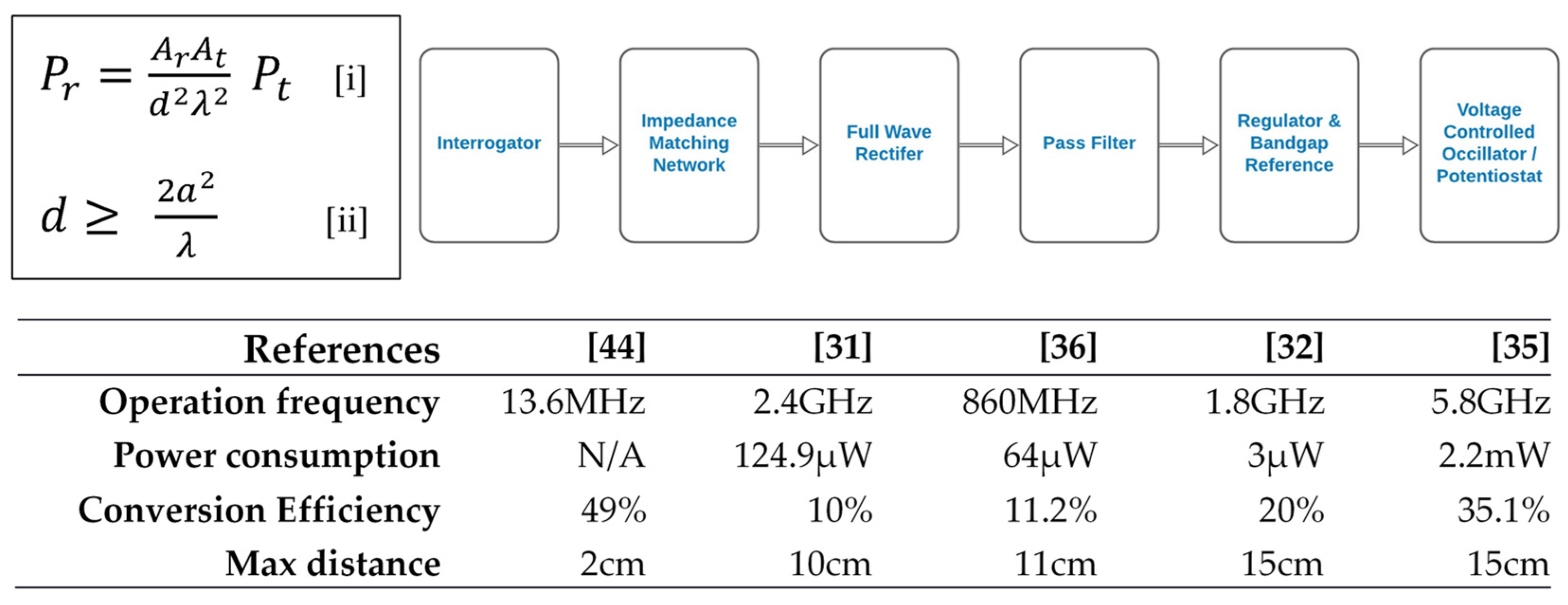
5.1. RF Power
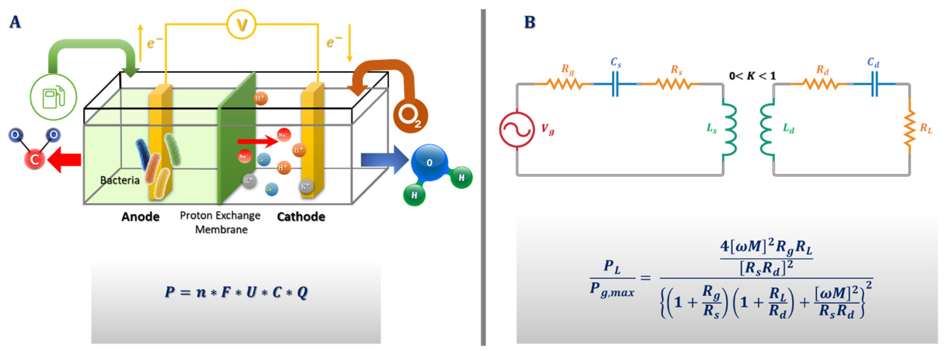
5.2. Biofuel Cell
5.3. Solar Cell
5.4. Inductive Power
6. Challenges in the Development of Glucose-Sensing CLs
6.1. Calibration Issues
6.2. Commercial Aspects
6.3. Recent and Future Applications
7. Conclusions
Author Contributions
Funding
Institutional Review Board Statement
Informed Consent Statement
Acknowledgments
Conflicts of Interest
References
- Guariguata, L.; Whiting, D.R.; Hambleton, I.; Beagley, J.; Linnenkamp, U.; Shaw, J.E. Global estimates of diabetes prevalence for 2013 and projections for 2035. Diabetes Res. Clin. Pract. 2013, 103, 137–149. [Google Scholar] [CrossRef] [PubMed]
- Roglic, G. WHO Global Report on Diabetes: A Summary. Int. J. Noncommunicable Dis. 2016, 1, 3–8. [Google Scholar] [CrossRef]
- Long, N.A.; Dagogo-Jack, S. The Comorbidities of Diabetes and Hypertension: Mechanisms and Approach to Target Organ Protection. J. Clin. Hypertens. 2011, 13, 244–251. [Google Scholar] [CrossRef] [PubMed]
- Badugu, R.; Lakowicz, J.R.; Geddes, C.D. Glucose Sensing Contact Lens: A Non-Invasive Technique for Continuous Physiological Glucose Monitoring. J. Fluoresc. 2003, 13, 371–374. [Google Scholar] [CrossRef] [PubMed]
- Villiger, M.; Stoop, R.; Vetsch, T.; Hohenauer, E.; Pini, M.; Clarys, P.; Rereira, F.; Clijsen, R. Evaluation and review of body fluids saliva, sweat and tear compared to biochemical hydration assessment markers within blood and urine. Eur. J. Clin. Nutr. 2017, 72, 69–76. [Google Scholar] [CrossRef]
- Choy, C.K.; Cho, P.; Chung, W.Y.; Benzie, I.F. Water-Soluble Antioxidants in Human Tears: Effect of the Collection Method. Investig. Ophthalmol. Vis. Sci. 2001, 42, 3130–3134. [Google Scholar]
- Zhang, J.; Hodge, W.; Hutnick, C.; Wang, X. Noninvasive Diagnostic Devices for Diabetes through Measuring Tear Glucose. J. Diabetes Sci. Technol. 2011, 5, 166–172. [Google Scholar] [CrossRef] [PubMed]
- March, F.W. A Noninvasive Ocular Glucose Sensor. Diabetes Technol. Ther. 2001, 3, 209–211. [Google Scholar] [CrossRef]
- Domschk, A.; March, W.F.; Kabilan, S.; Lowe, C. Initial Clinical Testing of a Holographic Non-Invasive Contact Lens Glucose Sensor. Diabetes Technol. Ther. 2006, 8, 89–93. [Google Scholar] [CrossRef]
- Kim, J.; Kim, M.; Lee, M.S.; Kim, K.; Ji, S.; Kim, Y.T.; Park, J.; Na, K.; Bae, K.H.; Kim, H.K.; et al. Wearable smart sensor systems integrated on soft contact lenses for wireless ocular diagnostics. Nat. Commun. 2017, 8, 14997. [Google Scholar] [CrossRef] [PubMed]
- Luana, V.H.; Hanb, J.H.; Kanga, H.W.; Lee, W. Ultra-sensitive non-enzymatic amperometric glucose sensors based on silver nanowire/graphene hybrid three-dimensional nanostructures. Results Phys. 2019, 15, 102761. [Google Scholar] [CrossRef]
- Chen, H.C.; Su, W.R.; Yeh, Y.C. Functional Channel of SWCNTs/Cu2O/ZnO NRs/Graphene Hybrid Electrodes for Highly Sensitive Nonenzymatic Glucose Sensors. ACS Appl. Mater. Interfaces 2020, 12, 32905–32914. [Google Scholar] [CrossRef] [PubMed]
- Hussaina, S.; Akbarc, K.; Vikramana, D.; Choia, D.C.; Kimd, S.J.; An, K.S.; Jung, S.; Jung, J. Highly Sensitive Enzymeless Glucose Sensor Based on 3D Graphene-Cu Hybrid Electrodes. New J. Chem. 2015, 39, 7481–7487. [Google Scholar] [CrossRef]
- Yao, H.; Shum, A.J.; Cowan, M.; Lähdesmäki, I.; Parviz, B.A. A contact lens with embedded sensor for monitoring tear glucose level. Biosens. Bioelectron. 2011, 26, 3290–3296. [Google Scholar] [CrossRef] [PubMed]
- Yao, H.; Marcheselli, C.; Afanasiev, A.; Lähdesmäki, I.; Parviz, B.A. A soft hydrogel contact lens with an encapsulated sensor for tear glucose monitoring. In Proceedings of the 2012 IEEE 25th International Conference on Micro Electromechanical Systems (MEMS), Paris, France, 29 January–2 February 2012. [Google Scholar]
- Yao, H.; Afanasiev, A.; Lähdesmäki, I.; Parviz, B.A. A dual microscale glucose sensor on a contact lens, tested in conditions mimicking the eye. In Proceedings of the 2011 IEEE 24th International Conference on Micro Electromechanical Systems, Cancun, Mexico, 23–27 January 2011. [Google Scholar]
- Yao, H.; Liao, Y.; Lingley, A.R.; Afanasiev, A.; Lähdesmäki, I.; Otis, B.P.; Parviz, B.A. A contact lens with integrated telecommunication circuit and sensors for wireless and continuous tear glucose monitoring. J. Micromech. Microeng. 2012, 22, 075007. [Google Scholar] [CrossRef]
- Holt-Hindle, P.; Nigro, S.; Asmussen, M.; Chen, A. Amperometric glucose sensor based on platinum–iridium nanomaterials. Electrochem. Commun. 2008, 10, 1438–1441. [Google Scholar] [CrossRef]
- Elsherif, M.; Hassan, M.U.; Yetisen, A.K.; Butt, H. Wearable Contact Lens Biosensors for Continuous Glucose Monitoring Using Smartphones. ACS Nano 2018, 12, 5452–5462. [Google Scholar] [CrossRef]
- Lin, Y.R.; Hung, C.C.; Chiu, H.Y.; Chang, B.H.; Li, B.R.; Cheng, S.J.; Yang, J.W.; Lin, S.F.; Chen, G.Y. Noninvasive Glucose Monitoring with a Contact Lens and Smartphone. Sensors 2018, 18, 3208. [Google Scholar] [CrossRef]
- Badugu, R.; Lakowicz, J.R.; Geddes, C.D. A glucose-sensing contact lens: A new approach to noninvasive continuous physiological glucose monitoring. In Proceedings of the Biomedical Optics 2004, San Jose, CA, USA, 24–29 January 2004. [Google Scholar]
- Phan, C.M.; Subbaraman, L.; Jones, L.W. The Use of Contact Lenses as Biosensors. Optom. Vis. Sci. 2016, 93, 419–425. [Google Scholar] [CrossRef]
- Kim, S.; Jeon, H.J.; Park, S.; Lee, D.Y.; Chung, E. Tear Glucose Measurement by Reflectance Spectrum of a Nanoparticle Embedded Contact Lens. Nature 2020, 10, 8254. [Google Scholar]
- Helwig, A.M.; Arnold, M.A.; Small, G.W. Evaluation of Kromoscopy: Resolution of glucose and urea. Appl. Opt. 2000, 39, 4715–4720. [Google Scholar] [CrossRef]
- Oliver, N.S.; Toumazou, C.; Cass, A.E.G.; Johnston, D.G. Glucose sensors: A review of current and emerging technology. Diabet. Med. 2009, 26, 197–210. [Google Scholar] [CrossRef]
- Cameron, B.D.; Anumula, H. Development of a real-time corneal birefringence compensated glucose sensing polarimeter. Diabetes Technol. Ther. 2006, 8, 156–164. [Google Scholar] [CrossRef] [PubMed]
- Park, J.; Kim, J.; Kim, S.Y.; Cheong, W.H.; Jang, J.; Park, Y.G.; Na, K.; Kim, Y.T.; Heo, J.H.; Lee, C.Y.; et al. Soft, smart contact lenses with integrations of wireless circuits, glucose sensors, and displays. Sci. Adv. 2018, 4, eaap9841. [Google Scholar] [CrossRef]
- Leonardi, M.; Pitchon, E.M.; Bertsch, A.; Renaud, P.; Mermoud, A. Acta Ophthalmologica, 1st ed.; John Wiley & Sons: Hoboken, NJ, USA, 2009. [Google Scholar]
- Craighead, H.G.; Cheng, J.; Hackwood, S. New display based on electrically induced index-matching in an inhomogeneous medium. Appl. Phys. Lett. 1982, 40, 22–24. [Google Scholar] [CrossRef]
- Lee, S.; Jo, I.; Kang, S.; Jang, B.; Moon, J.; Park, J.; Lee, S.; Rho, S.; Kim, Y.I.; Hong, H.B. Smart contact lenses with Graphene Coating for Electromagnetic Interference Shielding and Dehydration Protection. ACS Nano 2017, 11, 5318–5324. [Google Scholar] [CrossRef]
- Pandey, J.; Liao, Y.T.; Lingley, A.; Mirjalili, R.; Parviz, B.; Otis, B.P. A Fully Integrated RF-Powered Contact Lens with a Single Element Display. IEEE Trans. Biomed. Circuits Syst. 2010, 4, 454–461. [Google Scholar] [CrossRef] [PubMed]
- Liao, Y.T.; Yao, H.; Lingley, A.; Parviz, B.; Otis, B.P. A 3-μW CMOS Glucose Sensor for Wireless Contact-Lens Tear Glucose Monitoring. IEEE J. Solid-State Circuits 2012, 47, 335–344. [Google Scholar] [CrossRef]
- Blum, Z.; Pankratov, D.; Shleev, S. Powering electronic contact lenses: Current achievements, challenges, and perspectives. Expert Rev. Ophthalmol. 2014, 9, 269–273. [Google Scholar] [CrossRef]
- IEEE International Committee on Electromagnetic Safety (SCC39). IEEE Standard for Safety Levels with Respect to Human Exposure to Radio Frequency Electromagnetic Fields, 3 kHz to 300 GHz; IEEE: New York, NY, USA, 2006; pp. 1–238. [Google Scholar]
- Cheng, H.W.; Jeng, B.M.; Chen, C.Y.; Huang, H.Y.; Chiou, J.C.; Luo, C.H. The rectenna design on contact lens for wireless powering of the active intraocular pressure monitoring system. In Proceedings of the 35th Annual International Conference of the IEEE Engineering in Medicine and Biology Society (EMBC), Osaka, Japan, 3–7 July 2013. [Google Scholar]
- Chiou, J.C.; Hsu, S.H.; Liao, Y.T.; Huang, Y.C.; Yeh, G.T.; Kuei, C.K.; Dai, K.S. Toward a Wirelessly Powered On-Lens Intraocular Pressure Monitoring System. IEEE J. Biomed. Health Inform. 2016, 20, 1216–1224. [Google Scholar] [CrossRef]
- Reid, R.C.; Minteer, S.D.; Gale, B.K. Contact lens biofuel cell tested in a synthetic tear solution. Biosens. Bioelectron. 2015, 68, 142–148. [Google Scholar] [CrossRef] [PubMed]
- Kulkami, T.; Slaughter, G. Simulatenous glucose sensing and powering of glucometer. In Proceedings of the IEEE 60th International Midwest Symposium on Circuits and Systems (MWSCAS), Boston, MA, USA, 6–9 August 2017. [Google Scholar]
- Falk, M.; Andoralov, V.; Blum, Z.; Sotres, J.; Suyatin, D.B.; Ruzgas, T.; Arnebrant, T.; Shleev, S. Biofuel cell as a power source for electronic contact lenses. Biosens. Bioelectron. 2012, 37, 38–45. [Google Scholar] [CrossRef]
- Lingley, A.R.; Otis, B.P.; Shen, T.T.; Parviz, B.A. A contact lens with integrated micro solar cells. Microsyst. Technol. 2012, 18, 453–458. [Google Scholar] [CrossRef]
- Kenyon, R.V. A soft contact lens search coil for measuring eye movements. Vis. Res. 1985, 25, 1629–1633. [Google Scholar] [CrossRef]
- Chen, L.; Shaker, G.; Safavi-Naeini, S. Warpage-free antenna for smart contact lens applications. In Proceedings of the 2017 IEEE International Symposium on Antennas and Propagation & USNC/URSI National Radio Science Meeting, San Diego, CA, USA, 9–14 July 2017. [Google Scholar]
- Friis, H.T. A Note on a Simple Transmission Formula. Proc. IRE 1946, 34, 254–256. [Google Scholar] [CrossRef]
- Chen, L.; Shaker, G.; Safavi-Naeini, S. Energy harvesting system integrated on wearable contact lens. In Proceedings of the 2015 IEEE International Symposium on Antennas and Propagation & USNC/URSI National Radio Science Meeting, Vancouver, BC, Canada, 19–24 July 2015. [Google Scholar]
- He, Z.; Angenent, L.T. Application of Bacterial Biocathodes in Microbial Fuel Cells. Electroanalysis 2006, 18, 2009–2015. [Google Scholar] [CrossRef]
- Carreon-Bautista, S.; Erbay, C.; Han, A.; Sanchez-Sinencio, E. An Inductorless DC–DC Converter for an Energy Aware Power Management Unit Aimed at Microbial Fuel Cell Arrays. IEEE Trans. Emerg. Sel. Top. Power Electron. 2015, 3, 1109–1121. [Google Scholar] [CrossRef]
- Takamatsu, T.; Sijie, Y.; Shujie, F.; Xiaohan, L.; Miyake, T. Multifunctional High-Power Sources for Smart Contact Lenses. Adv. Funct. Mater. 2019, 30, 1906225. [Google Scholar] [CrossRef]
- Takamatsu, T.; Chen, Y.; Yoshimasu, T.; Nishizawa, M.; Miyake, T. Highly Efficient, Flexible Wireless-Powered Circuit Printed on a Moist, Soft Contact Lens. Adv. Mater. Technol. 2019, 1800671. [Google Scholar] [CrossRef]
- Kesler, M. Highly Resonant Wireless Power Transfer: Safe, Efficient, and Over Distance; WiTricity Corporation: Watertown, MA, USA, 2017; pp. 1–12. [Google Scholar]
- Lodwig, V.; Heinemann, L. Continuous Glucose Monitoring with Glucose Sensors: Calibration and Assessment Criteria. Diabetes Technol. Ther. 2003, 5, 572–586. [Google Scholar] [CrossRef]
- Keum, D.H.; Kim, S.K.; Koo, J.; Lee, G.H.; Jeon, C.; Mok, J.W.; Mun, B.H.; Lee, K.J.; Kamrani, E.; Joo, C.K.; et al. Wireless smart contact lens for diabetic diagnosis and therapy. Sci. Adv. 2020, 4. [Google Scholar] [CrossRef] [PubMed]
- Tseng, R.C.; Chen, C.C.; Hsu, S.M.; Chuang, H.S. Contact-Lens Biosensors. Sensors 2018, 18, 2651. [Google Scholar] [CrossRef]
- Moreddu, R.; Vigolo, D.; Yetisen, A.K. Contact Lens Technology: From Fundamentals to Applications. Adv. Healthc. Mater. 2019, 1900368. [Google Scholar] [CrossRef] [PubMed]
- Behar-Cohen, F.; Baillet, G.; de Ayguavives, T.; Garcia, P.O.; Krutmann, J.; Peña-García, P.; Remé, C.; Wolffsohn, J.S. Ultraviolet damage to the eye revisited: Eye-sun protection factor (E-SPF®), a new ultraviolet protection label for eyewear. Clin. Ophthalmol. 2014, 8, 87–104. [Google Scholar] [CrossRef] [PubMed]
- Di Girolamo, N.; Bosch, M.; Zamora, K.; Coroneo, M.T.; Wakefield, D.; Watson, S.L. A contact lens-based technique for expansion and transplantation of autologous epithelial progenitors for ocular surface reconstruction. Transplantation 2009, 87, 1571–1578. [Google Scholar] [CrossRef]
- Bobba, S.; Di Girolamo, N. Contact Lenses: A Delivery Device for Stem Cells to Treat Corneal Blindness. Optom. Vis. Sci. 2016, 93, 412–418. [Google Scholar] [CrossRef]
- Lan, S.; Zhang, X.; Taghinejad, M.; Rodrigues, S.; Lee, K.T.; Liu, Z.; Cai, W. Metasurfaces for Near-Eye Augmented Reality. ACS Photon. 2019, 6, 864–870. [Google Scholar] [CrossRef]
- Augmented-Reality Contact Lenses to be Human-Ready at CES. Available online: http://www.cnet.com/news/augmented-reality-contact-lenses-to-be-human-ready-at-ces/ (accessed on 14 May 2021).
- Glenn, M.S.; Arianpour, A.; Cookson, S.; Zhang, A.; Hendrik, L.; O’Brien, T.; Alvarez, A.; Ford, J.E. Wink-controlled polarization-switched telescopic contact lenses. Appl. Opt. 2015, 54, 9597–9605. [Google Scholar]
- Ascaso, F.J.; Huerva, V. Noninvasive Continuous Monitoring of Tear Glucose Using Glucose-Sensing Contact Lenses. Optom. Vis. Sci. 2016, 93, 426–434. [Google Scholar] [CrossRef] [PubMed]


Publisher’s Note: MDPI stays neutral with regard to jurisdictional claims in published maps and institutional affiliations. |
© 2021 by the authors. Licensee MDPI, Basel, Switzerland. This article is an open access article distributed under the terms and conditions of the Creative Commons Attribution (CC BY) license (https://creativecommons.org/licenses/by/4.0/).
Share and Cite
Bamgboje, D.; Christoulakis, I.; Smanis, I.; Chavan, G.; Shah, R.; Malekzadeh, M.; Violaris, I.; Giannakeas, N.; Tsipouras, M.; Kalafatakis, K.; et al. Continuous Non-Invasive Glucose Monitoring via Contact Lenses: Current Approaches and Future Perspectives. Biosensors 2021, 11, 189. https://doi.org/10.3390/bios11060189
Bamgboje D, Christoulakis I, Smanis I, Chavan G, Shah R, Malekzadeh M, Violaris I, Giannakeas N, Tsipouras M, Kalafatakis K, et al. Continuous Non-Invasive Glucose Monitoring via Contact Lenses: Current Approaches and Future Perspectives. Biosensors. 2021; 11(6):189. https://doi.org/10.3390/bios11060189
Chicago/Turabian StyleBamgboje, David, Iasonas Christoulakis, Ioannis Smanis, Gaurav Chavan, Rinkal Shah, Masoud Malekzadeh, Ioannis Violaris, Nikolaos Giannakeas, Markos Tsipouras, Konstantinos Kalafatakis, and et al. 2021. "Continuous Non-Invasive Glucose Monitoring via Contact Lenses: Current Approaches and Future Perspectives" Biosensors 11, no. 6: 189. https://doi.org/10.3390/bios11060189
APA StyleBamgboje, D., Christoulakis, I., Smanis, I., Chavan, G., Shah, R., Malekzadeh, M., Violaris, I., Giannakeas, N., Tsipouras, M., Kalafatakis, K., & Tzallas, A. (2021). Continuous Non-Invasive Glucose Monitoring via Contact Lenses: Current Approaches and Future Perspectives. Biosensors, 11(6), 189. https://doi.org/10.3390/bios11060189