Article

KMnF3:Yb3+,Er3+ Core-Active-Shell Nanoparticles with Broadband Down-Shifting Luminescence at 1.5 μm for Polymer-Based Waveguide Amplifiers

1
College of Information &Technology, Jilin Normal University, Siping 136000, China
2
College of Electronic Science & Engineering, Jilin University, Changchun 130012, China
*
Authors to whom correspondence should be addressed.
Nanomaterials 2019, 9(3), 463; https://doi.org/10.3390/nano9030463
Submission received: 22 February 2019 / Revised: 13 March 2019 / Accepted: 14 March 2019 / Published: 20 March 2019
(This article belongs to the Special Issue Nanosized Luminescent Materials: Advances and Applications)

Abstract

:
In this study, we prepared cubic-phase oleic-acid-coated KMnF3: Yb3+,Er3+ nanoparticles (NPs) and NaYF4:Yb3+,Er3+ NPs, which were about 23 nm. From the down-shifting emissions spectra of the two NPs obtained by 980 nm excitation, we observed the fact that the KMnF3: 18%Yb3+,1%Er3+ NPs were a luminescent material with a broadband near-infrared emission of 1.5 μm, and full-width at half-maximum (FWHM) of 55 cm−1, which was wider than that of the NaYF4: 18%Yb3+,1% NPs. Therefore, we believe that the oleic-acid-coated KMnF3:Yb3+,Er3+ NPs have great potential in fabricating broadband waveguide amplifiers. Through epitaxial growth of a KMnF3: Yb3+ active-shell on the core NPs, we compounded KMnF3:Yb3+,Er3+@KMnF3:Yb3+ core-active-shell NPs whose 1.5-μm infrared emissions intensity was 3.4 times as strong as that of the core NPs. In addition, we manufactured waveguide amplifiers using KMnF3:18%Yb3+,1%Er3+@KMnF3:2%Yb3+ NPs as the core materials of the waveguide amplifiers. When the input signal power was 0.2 mW and the pump power was 200 mW, we achieved a relative gain of 0.6 dB at 1534 nm in a 10-mm long waveguide.

Graphical Abstract

1. Introduction

Recently, erbium (Er3+)-doped waveguide amplifiers (EDWAs) have aroused a lot of research [1,2,3,4,5]. It is mainly due to two reasons: one is that Er3+ ions can send near-infrared emissions at around 1.5 μm (the 4I13/24I15/2 transition of Er3+ ions), the other is that EDWAs have great potential for application in the field of near-infrared optical communication technology [6,7,8]. Usually, EDWAs includes inorganic material waveguide amplifiers and polymer material waveguide amplifiers. Compared with inorganic material waveguide amplifiers using glasses [9,10,11] and oxide [12,13,14] as gain material, polymer material waveguide amplifiers have many advantages, such as low fabrication costs, simple processing, and easy integration with silicon [15,16,17]. Both Er3+-doped organic complexes [18,19] and Er3+-doped fluoride nanoparticles (NPs) [20,21] can be used to manufacture polymer material waveguide amplifiers. Compared with Er3+-doped organic complexes, Er3+-doped NPs have some advantages, for example high photostability [22,23].
However, it is difficult to achieve an Er3+-doped NP with a broadband emissions around 1.5 μm owing to the f–f transition of Er3+ ions [22]. So far, there have been many studies on the fluorescence properties of Er3+-doped NPs [24,25,26], but few works about the broadband near-infrared emissions (at around 1.5 μm) of Er3+-doped NPs. In this paper, we compounded KMnF3:18%Yb3+,1%Er3+ NPs with a broadband near-infrared emission. We analyzed the crystal structure and morphology of these NPs and measured the down-shifting luminescence properties. Then, we describe a method to improve the down-shifting luminescence intensity (at 1.5 µm) of KMnF3:18%Yb3+,1%Er3+ NPs by growing a KMnF3:2%Yb3+ active-shell. Finally, we fabricate waveguide amplifiers using KMnF3:18%Yb3+,1%Er3+@KMnF3:2%Yb3+ NPs as the gain medium. With an input signal power of 0.2 mW and a pump power of 200 mW, a relative optical gain of 0.6 dB at 1534 nm was obtained.
The main characteristics of this article are follows:
(1)
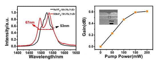
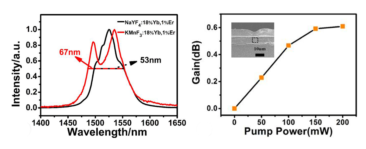
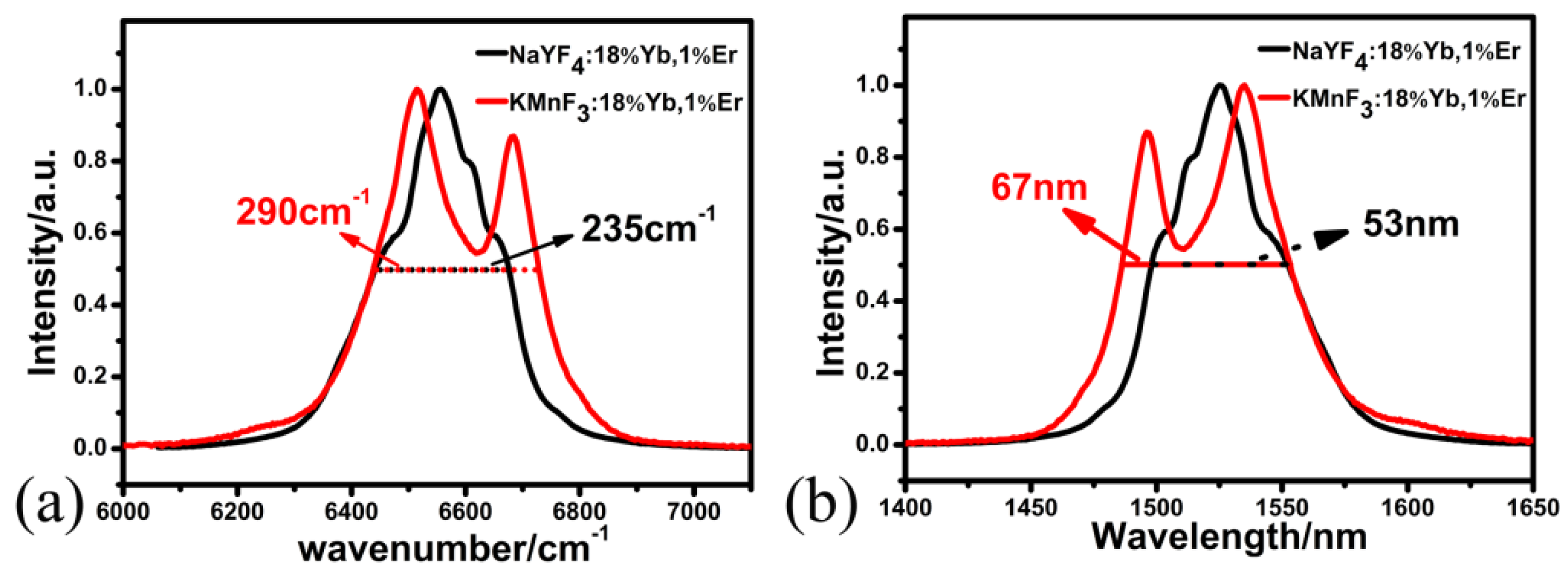
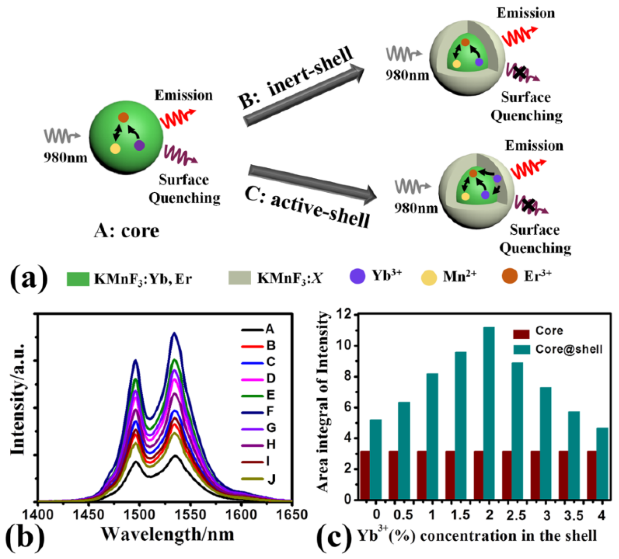
We prepared KMnF3:18%Yb3+,1%Er3+ NPs with a broadband 1.5-μm emission. Its full-width at half-maximum (FWHM) was about 290 cm−1 and was 55 cm−1 wider than that of NaYF4:18%Yb3+,1% NPs with the same size and phase.
(2)
We obtained KMnF3:18%Yb3+,1%Er3+@KMnF3:2%Yb3+ core-active-shell NPs with the strong and broadband 1.5-μm emission by coating a KMnF3:2%Yb3+ shell.

2. Experimental

2.1. Chemicals

All rare-earth nitrates Re (NO3)3·6H2O and rare-earth chloride ReCl3·6H2O we used came from Tianyi New Material, Jining, China. 1-octadecene (ODE) and oleic acid (OA) in the experiment came from the Alfa Aesar Company, Shanghai, China. The other chemical reagents were produced by Sinopharm Chemical Reagent, Beijing, China.

2.2. Synthetic Procedures

Synthesis of NaYF4:18%Yb3+,1%Er3+ NPs was conducted with a high-boiling solvent method which used the following steps [27].
The following chemical reagents: 0.01 mmol ErCl3·6H2O, 0.18 mmol ErCl3·6H2O, and 0.81 mmol ErCl3·6H2O were added into a 100-mL four-necked flask containing 6 mL OA and 15 mL ODE. The solution was heated to 150 °C and kept for 30 min under the protection of an Ar gas flow to remove residual O2 and water. The solution was naturally cooled to room temperature. A 10-mL methanol solution containing 0.15 g NH4F and 0.1 g NaOH was slowly added into in the 100-mL four-necked flask. Then, the reaction solution was heated to 50 °C for 30 min under stirring. Finally, the solution was heated to 280 °C and kept for 60 min. The solution was naturally cooled to room temperature, and cleaned by cyclohexane and ethanol four times.
Synthesis of the KMnF3:18%Yb3+,1%Er3+ core NPs by a solvothermal method had the following steps [28,29].
The following chemical reagents: 12 mmol KOH, 5 mL deionized water, 5 mL ethanol, and 10 mL OA were added into a 50-mL beaker. The reaction solution was stirred for 30 min at room temperature. While stirring, 0.072 mmol Yb (NO3)3·6H2O, 0.004 mmol Er (NO3)3·6H2O, and 0.324 mmol MnCl2 were added to the solution. After that, 3.5 mmol KF was added to the solution and the solution was stirred continuously for 30 min. Finally, the solution was transferred into a 50-mL reaction kettle and heated to 200 °C for 1 h. The solution of KMnF3:Yb3+,Er3+ NPs can be used to synthetize the core-shell NPs. The samples for measuring fluorescence spectra were washed by cyclohexane and ethanol four times.
Synthesis of the KMnF3:18%Yb3+,1%Er3+@KMnF3:2%Yb3+ core-active-shell NPs by a solvothermal method had following steps [29,30].
The following chemical reagents: 12 mmol KOH, 5 mL deionized water, 5 mL ethanol, and 10 mL OA were added into a 100-mL beaker. The reaction solution was stirred at room temperature for 30 min. Then, 0.008 mmol Yb (NO3)3·6H2O and 0.392 mmol MnCl2 were added into the solution. The solution of 0.4 mmol KMnF3:Yb3+,Er3+ NPs was added into the beaker. The reaction solution was stirred continuously for 30 min. While stirring, 3.5 mmol KF was added into the reaction solution and the solution was stirred continuously for another 30 min. Finally, the reaction solution was transferred into two 50-mL reaction kettles and heated to 200 °C for 12 h. These products were washed with ethanol and cyclohexane four times.
Fabrication processes of the KMnF3:18%Yb3+,1%Er3+@KMnF3:2%Yb3+ core-active-shell NPs doped polymer waveguides were used the following steps [5,31].
Step 1: form a PMMA (polymethyl methacrylate) film-base cladding layer by spin-coating PMMA polymers on silicon substrate-based thick silicon dioxide layer, and bake the silicon substrates for 2 h at 120 °C. Step 2: an inductively coupled plasma (ICP) etching approach and classical photolithography are used to form waveguide patterns on the PMMA film-base cladding layer. Step 3: form the core waveguides by spin-coating the mixture of KMnF3:18%Yb3+,1%Er3+@KMnF3:2%Yb3+ core-active-shell NPs and PMMA into the grooves, and cure it at 100 °C for 2.5 h. Finally, a PMMA polymer is spin-coated upon the core waveguides layer. The fabrication processes is shown in Supplementary Materials Figure S1.

2.3. Characterization

The crystalline phase of as-synthesized NPs was characterized by a Model Rigaku Ru-200b (Rigaku, Tokyo, Japan), when λ = 1.5406 Å and scanning range was 10–70°. The transmission electron microscope (TEM) image of as-synthesized NPs was recorded by a H-600 electron microscope under the condition of 200 kV (Hitachi, Tokyo, Japan). Under a 980 nm excitation, the fluorescence spectrum of as-synthesized NPs was recorded by a SPEX 1000M spectrometer (Horiba Group, Kyoto, Japan). The Fourier transform infrared spectrum of the as-synthesized NPs was characterized by a FTIR-1500 (Josvok, Tianjin, China), under the scanning range of 1000 cm1–4000 cm1. The scanning electron microscopy (SEM) image of the waveguide was characterized by a JSM-7500F (Jeol, Tokyo, Japan).

3. Results and Discussion

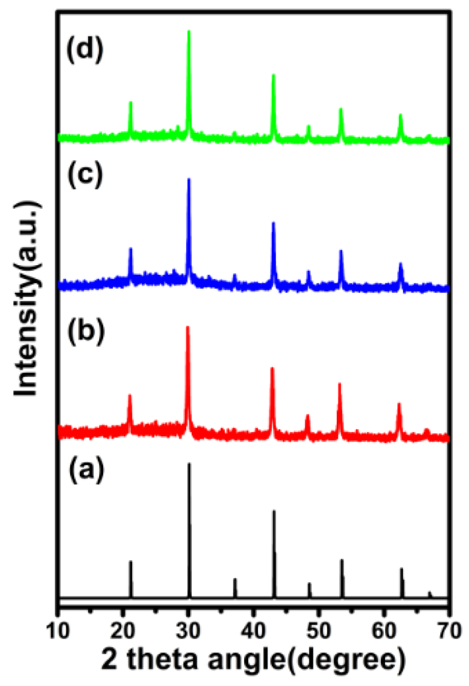
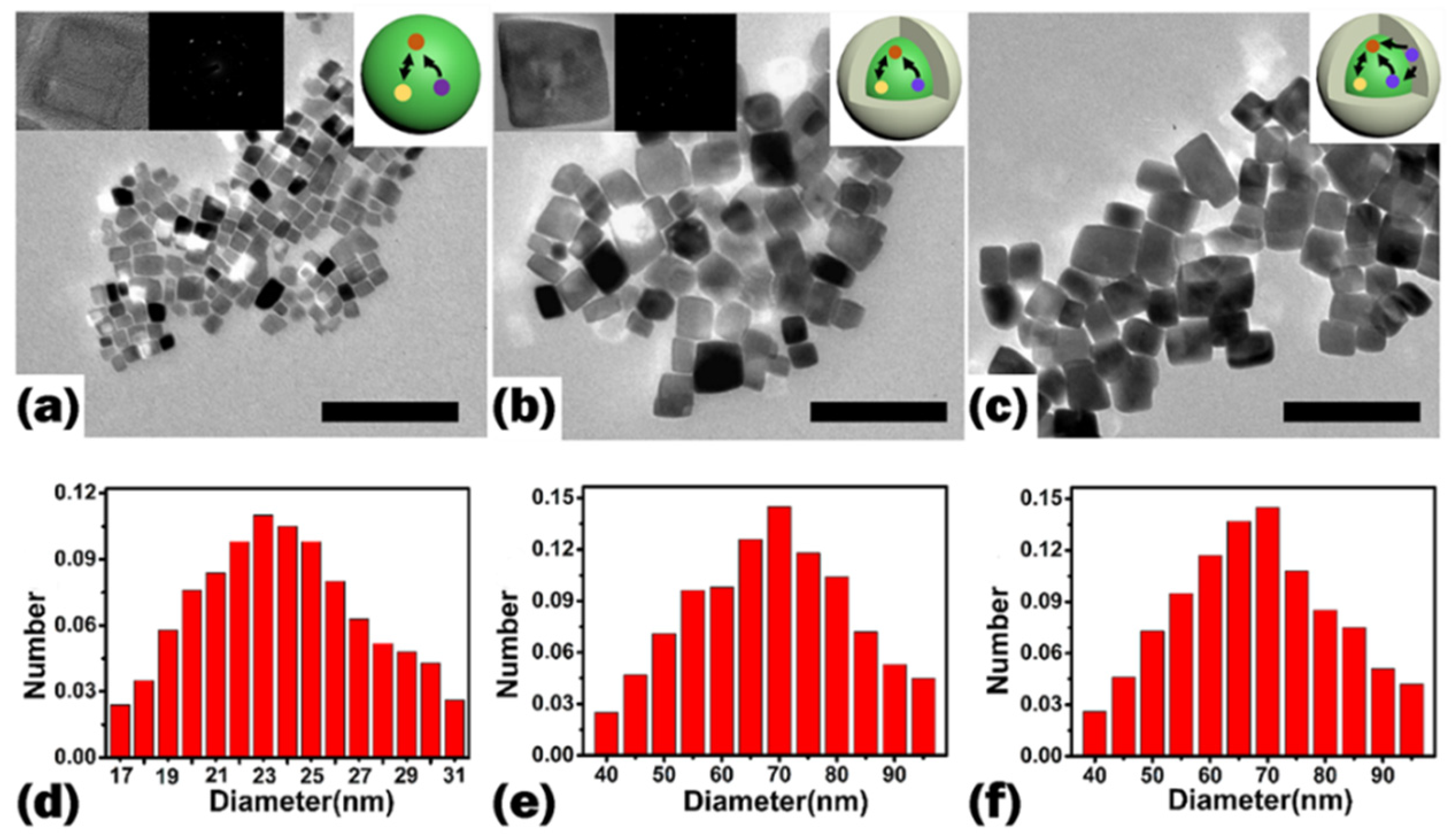
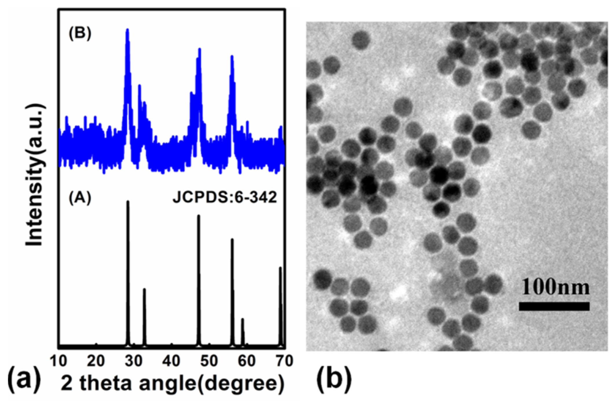
3.1. Crystal Structure and Morphology

In order to get the crystal structure of as-synthesized KMnF3:18%Yb3+,1%Er3+ core NPs, KMnF3:18%Yb3+,1%Er3+@KMnF3 core-inert-shell NPs and KMnF3:18%Yb3+,1%Er3+@KMnF3:2%Yb3+ core-active-shell NPs, we measured the XRD (X-Ray Diffraction) of these samples, and the results are shown in Figure 1. The diffraction peaks of the samples coincided well with the pure cubic-phase of KMnF3 (JCPDS-82-1334). The data suggests that the samples were pure cubic-phase KMnF3 NPs. In addition, the morphology of the above samples was analyzed by TEM. Figure 2 shows TEM images and size distributions of the core NPs, the core-inert-shell NPs, and the core-active-shell NPs, respectively. The result shows that the KMnF3 core NPs were cubic and monodisperse without any aggregate. The average diameter of the core NPs was around 23 ± 5 nm. When the core NPs were coated with an inert-shell or active-shell, KMnF3:18%Yb3+,1%Er3+@KMnF3 core-inert-shell NPs and KMnF3:18%Yb3+,1%Er3+@KMnF3:2%Yb3+ core-active-shell NPs were cubic, and the morphology of the two NPs did not change. The average sizes of the core-inert-shell NPs and the core-active-shell NPs were both about 65 ± 20 nm.
We also synthesized NaYF4:18%Yb3+,1%Er3+ NPs via a high-boiling solvent method. In order to get the phase of as-synthesized NaYF4:18%Yb3+,1%Er3+ NPs, we measured the XRD of the product, and the result is shown in Figure 3a. The diffraction peaks of the as-synthesized product coincided well with pure cubic-phase NaYF4 (JCPDS-6-342), and the results indicates that the products were pure cubic-phase NaYF4 NPs. Figure 3b shows the TEM of the NaYF4:18%Yb3+,1%Er3+ NPs. The data suggests that the product was spherical without agglomeration and the size of the as-synthesized product was 23 ± 3 nm.

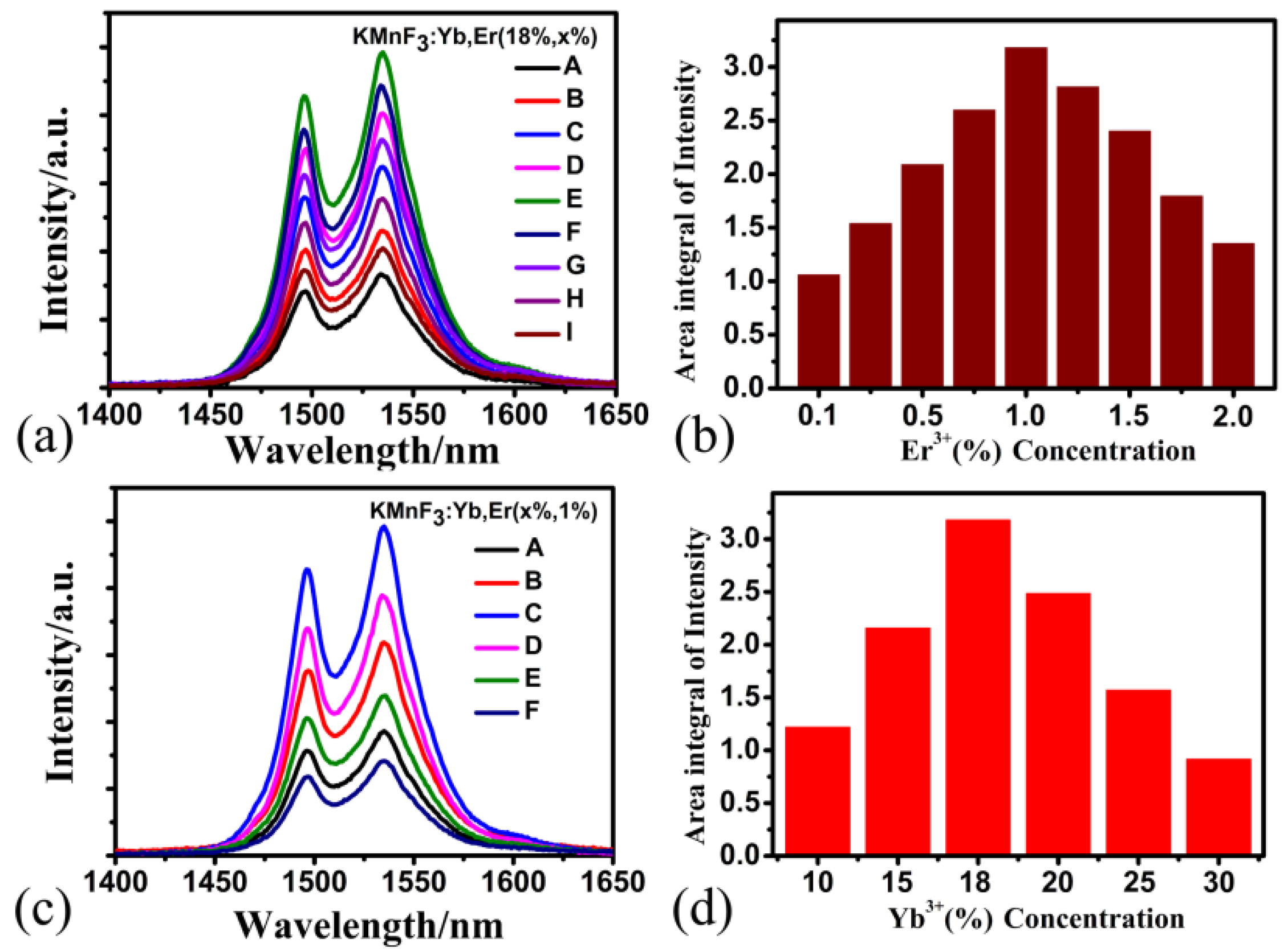
3.2. Down-Shifting Luminescence Properties

In order to evaluate the impact of matrix material on the down-shifting fluorescence spectra (around 1.5 µm) of Yb3+-Er3+-co-doped fluoride nanoparticles, we compounded and characterized two NPs with the same size and crystal phase. Firstly, the NaYF4:18%Yb3+,1%Er3+ NPs and the KMnF3:18%Yb3+,1% Er3+ NPs were both cubic phase and had the same size. Then, the down-shifting fluorescence spectra of NaYF4:18%Yb3+,1%Er3+ NPs and KMnF3:18%Yb3+,1%Er3+ NPs were characterized. Figure 4 is the normalized down-shifting fluorescence spectra at maximum value of the two NPs excited by a 980-nm laser diode. From Figure 4, we can find the following: the down-shifting fluorescence spectra of KMnF3:Yb3+, Er3+ NPs had two emission peaks near the 1496 nm and 1534 nm bands, respectively, and the FWHM was 290 cm−1. The appearance of the two peaks of KMnF3:Yb3+,Er3+ NPs was due to stark splitting of the emitting level 4I13/2. In contrast, the down-shifting fluorescence spectra of NaYF4:Yb3+,Er3+ NPs had only one emission peak at 1525 nm, and the FWHM was 235 cm-1. The difference in down-shifting fluorescence spectra is attributed to differences in crystal filed in various host crystals. The FWHM of down-shifting fluorescence spectra of the KMnF3:Yb3+,Er3+ NPs was 55 cm-1 wider than that of NaYF4:Yb3+,Er3+ NPs. This means, when Er3+ and Yb3+ have the same concentration, the KMnF3:Yb3+,Er3+ NPs had a much wider FWHM of down-shifting fluorescence spectra than that of NaYF4:Yb3+,Er3+ NPs, with the same size and crystal phase, which shows the KMnF3:Yb3+,Er3+ NPs are a more suitable gain material for broadband waveguide amplifiers.
It is well known that the luminescence properties of Yb3+ and Er3+ co-doped fluoride nanoparticles can be influenced by the doping concentration of Yb3+ ions and Er3+ ions. In order to obtain the Yb3+ and Er3+ co-doped KMnF3 NPs with strong near-infrared emission at 1.5 μm, we synthesized a series of KMnF3 NPs with different concentrations of Yb3+ and Er3+ ions. Figure 5a shows the study of Er3+ ions concentration dependent down-shifting fluorescence of KMnF3 NPs and the down-shifting fluorescence of KMnF3:18%Yb3+,x%Er3+ (x = 0.1, 0.25, 0.5, 0.75, 1, 1.25, 1.5, 1.75, 2) NPs under diode-laser excitation at 980 nm. Figure 5b shows the variation of fluorescence intensity of KMnF3 NPs and concentration of Er3+ ions. We can see that when the concentration of Er3+ ions is 1%, the down-shifting luminescence intensity of KMnF3 NPs gets its maximum value, and when the concentration of Er3+ ions is lower or higher than 1%, the luminescence intensity is lower than the maximum intensity. The experimental results shown in Figure 5b indicate that the optimum concentration of Er3+ ions doped with KMnF3:18%Yb3+,x%Er3+ NPs is 1%.
At the same time, we also investigated the effect of Yb3+ ions on the fluorescence intensity of KMnF3 NPs. Figure 5c shows the down-shifting fluorescence spectra of KMnF3:x%Yb3+,1%Er3+ NPs excited by a 980 nm laser diode. We can see from Figure 5d that when the concentration of Yb3+ ions is 18%, the down-shifting fluorescence intensity of KMnF3 NPs obtains its maximum value, which indicates that the optimum concentration of Yb3+ ions doped with KMnF3: x%Yb3+,1%Er3+ NPs is 18%.
In this part, we demonstrate and analyze the effect of Yb3+ concentrations in the shell on the down-shifting fluorescence intensity of KMnF3 core-shell NPs. Figure 6a shows the schematic illustration of KMnF3:18%Yb3+,1%Er3+ NPs, KMnF3:18%Yb3+,1%Er3+@KMnF3 NPs, and KMnF3:18%Yb3+,1%Er3+@KMnF3:2%Yb3+ NPs. The down-shifting fluorescence spectra and its corresponding enhancement ratio of KMnF3 core NPs and a series of KMnF3 core-shell NPs with different Yb3+ concentrations in the shell are shown in Figure 6b,c, respectively. In Figure 6b, the down-shifting fluorescence spectrum corresponding to curve A indicates the KMnF3:18%Yb3+,1%Er3+ core NPs had the weakest near-infrared emission from 4I13/24I15/2 transition of Er3+ ions. The reason is because the high-specific surface area of the KMnF3:Yb3+,Er3+ core NPs led to a large number of surface defects which can quench the energy of pump light. After the core NPs were coated by inert shells (the shell without Yb3+ ions), which can limit the efficiency of surface quenching [26,32,33], the down-shifting fluorescence intensity of KMnF3:18%Yb3+,1%Er3+@KMnF3 core-inert-shell NPs increased. As shown in Figure 6c, the down-shifting fluorescence intensity of the KMnF3:Yb3+,Er3+ core-inert-shell NPs was 1.6 times that of KMnF3:Yb3+,Er3+ core NPs. Then, the core NPs were coated by active shells which were doped with Yb3+ ions. The intensity of the fluorescence spectrum of the KMnF3:Yb3+,Er3+@KMnF3:x%Yb3+ (x = 0.5, 1, 1.5, 2, 2.5, 3, 3.5, 4) core-active-shell NPs are shown by curves C–J in Figure 6b. From the enhancement ratio of the KMnF3 core-active-shell NPs with different Yb3+ concentrations shown in Figure 6c, we can see that when the concentration of Yb3+ is 2%, the down-shifting luminescence intensity of the core-active-shell NPs reaches its maximum value which was 2.1 times that of the core-inert-shell NPs under 980 nm excitation. The reason is that the KMnF3:2%Yb3+ active shell can transfer the energy of pump light to the core region efficiently, while overcoming surface quenching effect [34,35,36,37]. In addition, we measured the fluorescent decay curves of the 4I13/2 level of Er3+ ions in KMnF3:18%Yb3+,1%Er3+ core NPs, KMnF3:18%Yb3+,1%Er3+@KMnF3 core-inert-shell NPs, and KMnF3:18%Yb3+,1%Er3+@KMnF3:2%Yb3+ core-active-shell NPs, as shown in Figure S2. The data agrees well with the intensity of these NPs. We measured the down-shifting fluorescence of KMnF3:18%Yb3+,1%Er3+@KMnF3:2%Yb3+ core-active-shell NPs was excited by different power of 980 nm, as shown in Figure S3. The experimental results indicate that the KMnF3:18%Yb3+,1%Er3+@ KMnF3:2%Yb3+ core-active-shell NPs with strong broadband down-shifting luminescence has great advantages as gain medium for waveguide amplifiers.

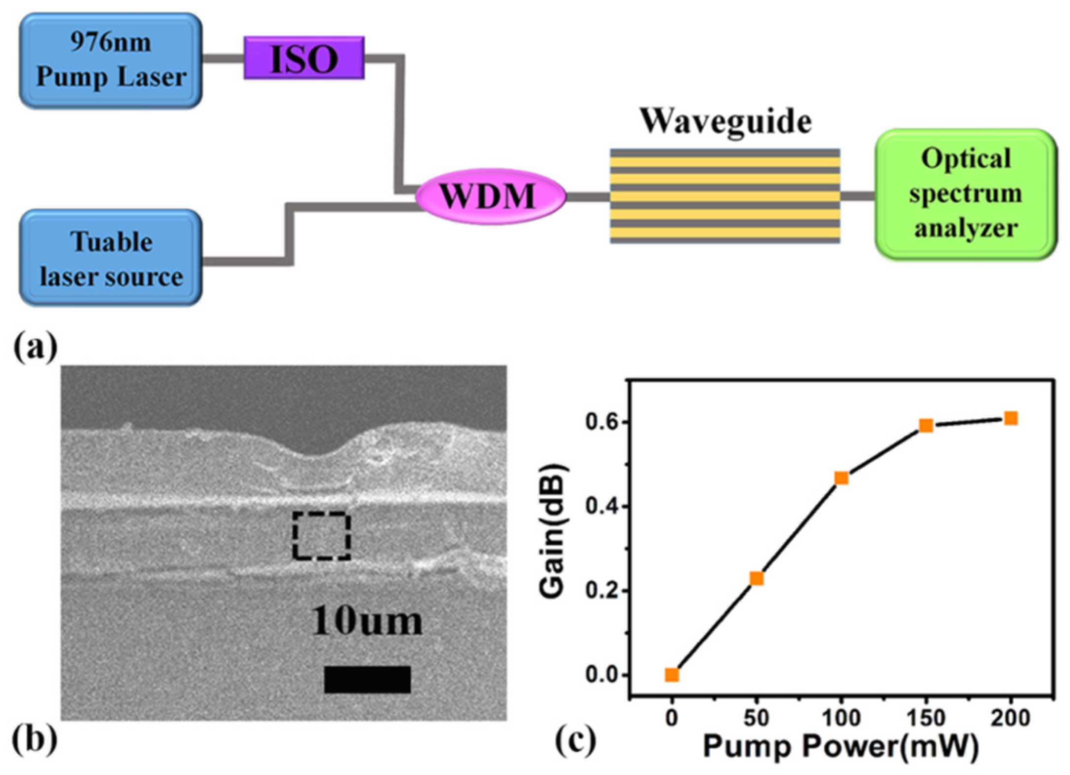
3.3. Optical Waveguide Amplifiers Based on KMnF3:18%Yb3+,1%Er3+@KMnF3:2%Yb3+ NPs

A FTIR spectrum of the KMnF3:18%Yb3+,1%Er3+@KMnF3:2%Yb3+ core-active-shell NPs is shown in Figure 7. The absorptions at around 3007 cm−1 was due to the symmetric stretching vibration of the =C–H group. The peaks located at 2856 cm−1 and 2925 cm−1 can be assigned as the symmetric and asymmetric vibration of the –CH2 group. The absorptions at 1545 cm−1 and 1464 cm−1 are attributed to the asymmetric and symmetric vibration of the group (–COOH) of the oleic acid coating. As the above result shows, that core-active-shell NPs were coated by the oleic acid ligand. Then, the KMnF3:18%Yb3+,1%Er3+@KMnF3:2%Yb3+ core-active-shell NPs were dispersed into PMMA as the gain medium of polymer waveguides.
We manufactured polymer waveguide amplifiers whose gain medium was made by mixing KMnF3:18%Yb3+,1%Er3+@KMnF3:2%Yb3+ with strong near-infrared luminescence and PMMA evenly. The schematic of our polymer waveguide amplifier gain testing system is shown in Figure 8a. In our gain testing system, a 980-nm laser and a tunable laser source (Santec TSL-210, Aichi, Japan) were separately used as pump light and signal light, where the wavelength range of Santec TSL-210 was 1510 nm to 1590 nm. After the pump light passed through the isolator (ISO), a wavelength division multiplexer (WDM) was used to couple the ISO’s output and the signal light into an optical fiber whose output light passed through an optical waveguide amplifier. The output of the optical waveguide amplifier was monitored by the Ando AQ-6315A spectrometer (optical spectrum analyzer, OSA). The morphology of the cross-section of the KMnF3:18%Yb3+,1%Er3+@KMnF3:2%Yb3+ NPs doped waveguide is displayed by Figure 8b. The following equation can be used to calculate the relative gain of our waveguide amplifiers [19].
G a i n [ d B ] = 10 l o g ( P s o u t p P s o u t ) = 10 l o g ( P s o u t p ) 10 l o g ( P s o u t )
where P s o u t p and P s o u t represent the output signal powers in cases with and without pump light [19], respectively. Figure 8c shows the curve of relative gain versus pump power at 980 nm of a 10 mm-long waveguide, when the input signal power and wavelength are 0.2 mW and 1534 nm, respectively. As Figure 8c shows, when the pump power is in the range of 0 mW to 150 mW, the relative gain increases rapidly with the increase of the pump power. When the pump power is 200 mW, the maximum relative gain of 0.6 dB is obtained.
In this paper, we synthesized KMnF3:18%Yb3+,1%Er3+@KMnF3:2%Yb3+ NPs with broadband near-infrared emissions at 1.5 µm and constructed KMnF3:18%Yb3+,1%Er3+@KMnF3:2%Yb3+ core-active-shell NPs doped with polymer waveguides, but we did not obtain broadband optical gain. It is clear that the luminescence intensity of the core-active-shell NPs and fabrication method of the optical waveguides would affect the testing result. A study on the above factors affecting the optical gain of the waveguide amplifiers is in progress and will be the subject of a future paper.

4. Conclusions

In conclusion, we synthesized KMnF3:18%Yb3+,1%Er3+ NPs with a broadband down-shifting emissions under 980 nm of excitation, and the FWHM of the down-shifting luminescence spectra of this NPs was 290 cm−1. The KMnF3:18%Yb3+,1%Er3+@KMnF3:2%Yb3+ NPs was prepared by coating a KMnF3:2%Yb3+ active-shell on KMnF3:Yb3+,Er3+ core NPs. The intensity of the core NPs was enhanced 3.4 times after coating a KMnF3:2%Yb3+ active-shell. We manufactured polymer waveguide amplifiers by using KMnF3:18%Yb3+,1%Er3+@KMnF3:2%Yb3+ NPs with PMMA as the gain medium. The relative optical gain of our wave guide amplifiers was 0.6 dB, when the input signal power and pump power were 0.2 mW and 200 mW, respectively.

Supplementary Materials

The following are available online at https://www.mdpi.com/2079-4991/9/3/463/s1, Figure S1: Schematic illustration of fabrication processes of the KMnF3:18%Yb3+,1%Er3+@KMnF3:2%Yb3+ core-active-shell NPs-doped polymer waveguides. Figure S2: The fluorescent decay curves of the 4I13/2 level of Er3+ ions in KMnF3:18%Yb3+,1%Er3+ core NPs, KMnF3:18%Yb3+,1%Er3+@KMnF3 core-inert-shell NPs and KMnF3:18%Yb3+,1%Er3+@KMnF3:2%Yb3+ core-active-shell NPs. Figure S3: (a) The down-shifting fluorescence of KMnF3:18%Yb3+,1%Er3+@KMnF3:2%Yb3+ core-active-shell NPs was excited by different power of 980 nm. (b) The relationship between luminous intensity and pump power.

Author Contributions

Y.Z., G.Q., and W.Q. conceived and designed the experiments; Y.Z., P.L., and D.W. performed the experiments; D.Z. (Dan Zhao), Z.Q., D.Z. (Daming Zhang), and F.W. analyzed the data, contributed reagents/materials/analysis tools. Y.Z. wrote the paper. All authors have read and approved the final manuscript.

Funding

This research was funded by the Science and Technology Development Plan Project of Jilin Province of China (No1. 20180520199JH, No. 2.20180520191JH); Science and Technology Project of the Jilin Provincial Education Department of China (No. JJKH20180762KJ); and The National Natural Science Foundation of China (No. 21701047).

Conflicts of Interest

The authors declare no conflict of interest.

References

  1. Zhang, M.L.; Zhang, W.W.; Wang, F.; Zhao, D.; Qu, C.Y.; Wang, X.B.; Yi, Y.J.; Cassan, E.; Zhang, D.M. High-gain polymer optical waveguide amplifiers based on core-shell NaYF4/NaLuF4:Yb3+,Er3+ NPs-PMMA covalent-linking nanocomposites. Sci. Rep. 2016, 6, 36729. [Google Scholar] [CrossRef] [PubMed]
  2. Ghosh, R.N.; Shmulovich, J.; Kane, C.F.; Barros, M.R.D. 8-mW threshold Er3+-doped planar waveguide amplifier. IEEE Photonics Technol. Lett. 2016, 8, 518–520. [Google Scholar] [CrossRef]
  3. Sergio, A.; Vázquez, C.; Dijkstra, M.; Bernhardi, E.H.; Ay, F.; Pollnau, M. Erbium-doped spiral amplifiers with 20 dB of net gain on silicon. Opt. Express 2014, 22, 25993–26004. [Google Scholar] [CrossRef]
  4. Bo, S.; Wang, J.; Zhao, H.; Ren, H.; Wang, Q.; Xu, G.; Zhang, X.; Liu, X.; Zhen, Z. LaF3:Er,Yb doped sol-gel polymeric optical waveguide amplifiers. Appl. Phys. B 2008, 91, 79–83. [Google Scholar] [CrossRef]
  5. Zhang, D.; Chen, C.; Chen, C.M.; Ma, C.S.; Zhang, D.M.; Bo, S.H.; Zhen, Z. Optical gain at 1535 nm in LaF3:Er,Yb nanoparticle-doped organic-inorganic hybrid material waveguide. Appl. Phys. Lett. 2007, 91, 161109. [Google Scholar] [CrossRef]
  6. Ye, H.Q.; Li, Z.; Peng, Y.; Wang, C.C.; Li, T.Y.; Zheng, Y.X.; Sapelkin, A.; Adamopoulos, G.; Hernández, I.; Wyatt, P.B.; et al. Organo-erbium systems for optical amplification at telecommunications wavelengths. Nat. Mater. 2014, 13, 382–386. [Google Scholar] [CrossRef]
  7. Wong, W.H.; Chan, K.S.; Pun, E.Y.B. Ultraviolet direct printing of rare-earth-doped polymer waveguide amplifiers. Appl. Phys. Lett. 2005, 87, 011103. [Google Scholar] [CrossRef]
  8. Wang, T.J.; Zhao, D.; Zhang, M.L.; Yin, J.; Song, W.Y.; Jia, Z.X.; Wang, X.B.; Qin, G.S.; Qin, W.P.; Wang, F.; et al. Optical waveguide amplifiers based on NaYF4:Er3+,Yb3+ NPs-PMMA covalent-linking nanocomposites. Opt. Mater. Express 2015, 5, 469–477. [Google Scholar] [CrossRef]
  9. Shen, X.; Wang, Y.; Guo, H.; Liu, C. Near-infrared carbon-implanted Er3+/Yb3+ co-doped phosphate glass waveguides. Front. Optoelectron. 2018, 11, 291–295. [Google Scholar] [CrossRef]
  10. Chen, C.; He, R.; Tan, Y.; Wang, B. Optical ridge waveguides in Er3+/Yb3+ co-doped phosphate glass produced by ion irradiation combined with femtosecond laser ablation for guided-wave green and red upconversion emissions. Opt. Mater. 2016, 51, 185–189. [Google Scholar] [CrossRef]
  11. Zhu, Q.F.; Shen, X.L.; Zheng, R.L.; Lv, P.; Guo, H.T.; Li, W.N.; Liu, C.X. Waveguiding structures in Yb3+-doped phosphate glasses by double-energy proton and single-energy carbon-ion implantations. Mater. Res. Express 2018, 5, 016404. [Google Scholar] [CrossRef]
  12. Khu, V.; Steve, M. Tellurium dioxide Erbium doped planar rib waveguide amplifiers with net gain and 2.8dB/cm internal gain. Opt. Express 2010, 18, 19192–19200. [Google Scholar] [CrossRef]
  13. Avram, D.; Tiseanu, I.; Vasile, B.S.; Florea, M.; Tiseanu, C. Near infrared emission properties of Er doped cubic sesquioxides in the second/third biological windows. Sci. Rep. 2018, 8, 18033. [Google Scholar] [CrossRef]
  14. Bradley, J.D.B.; Silva, M.C.; Gay, M.; Bramerie, L.; Driessen, A.; Wörhoff, K.; Simon, J.C.; Pollnau, M. 170 Gbit/s transmission in an erbium-doped waveguide amplifier on silicon. Opt. Express 2009, 17, 22201–22208. [Google Scholar] [CrossRef]
  15. Bo, S.H.; Hu, J.; Chen, Z.; Wang, Q.; Xu, G.M.; Liu, X.H.; Zhen, Z. Core-shell LaF3:Er,Yb nanocrystal doped sol–gel materials as waveguide amplifiers. Appl. Phys. B 2009, 97, 665–669. [Google Scholar] [CrossRef]
  16. Kumar, G.A.; Chen, C.W.; Ballato, J.; Riman, R.E. Optical Characterization of Infrared Emitting Rare-Earth-Doped Fluoride Nanocrystals and Their Transparent Nanocomposites. Chem. Mater. 2007, 19, 1523–1528. [Google Scholar] [CrossRef]
  17. Lei, K.L.; Chow, C.F.; Tsang, K.C.; Lei, E.N.Y.; Roy, V.A.L.; Lam, M.H.W.; Lee, C.S.; Pun, E.Y.B.; Li, J. Long aliphatic chain coated rare-earth nanocrystal as polymer-based optical waveguide amplifiers. J. Mater. Chem. 2010, 20, 7526–7529. [Google Scholar] [CrossRef]
  18. Najar, A.; Lorrain, N.; Ajlani, H.; Charrier, J.; Oueslati, M.; Haji, L. Er3+ doping conditions of planar porous silicon waveguides. Appl. Surf. Sci. 2009, 256, 581–586. [Google Scholar] [CrossRef]
  19. Wong, W.H.; Pun, E.Y.B.; Chan, K.S. Er3+-Yb3+ codoped polymeric optical waveguide amplifiers. Appl. Phys. Lett. 2004, 84, 176–178. [Google Scholar] [CrossRef]
  20. Zhai, X.S.; Li, J.; Liu, S.S.; Liu, X.Y. Enhancement of 1.53 μm emission band in NaYF4:Er3+,Yb3+,Ce3+ nanocrystals for polymer-based optical waveguide amplifiers. Opt. Mater. Express 2013, 3, 270–277. [Google Scholar] [CrossRef]
  21. Wang, Y.; Guo, X.Y.; Liu, S.S.; Zheng, K.Z.; Qin, Z.K.; Qin, W.P. Controllable synthesis of β-NaLuF4:Yb3+,Er3+ nanocrystals and their application in polymer-based optical waveguide amplifiers. J. Fluor. Chem. 2015, 175, 125–128. [Google Scholar] [CrossRef]
  22. Haase, M.; Schafer, H. Upconverting Nanoparticles. Angew. Chem. Int. Ed. 2011, 50, 5808–5829. [Google Scholar] [CrossRef]
  23. Liu, Y.; Tu, D.; Zhu, H.; Chen, X. Lanthanide-doped luminescent nanoprobes: Controlled synthesis, optical spectroscopy, and bioapplications. Chem. Soc. Rev. 2013, 42, 6924–6958. [Google Scholar] [CrossRef]
  24. Zhang, Y.L.; Shi, Y.D.; Qin, Z.K.; Song, M.X.; Qin, W.P. Synthesis of small Ce3+-Er3+-Yb3+ tri-doped BaLuF5 active-core-active-shell-active-shell nanoparticles with strong down conversion luminescence at 1.5 μm. Nanomaterials 2018, 8, 615. [Google Scholar] [CrossRef]
  25. Khaydukov, K.V.; Rocheva, V.V.; Savelyev, A.G.; Sarycheva, M.E.; Asharchuk, I.M. Synthesis of NaLuF4: Er3+, Yb3+, Ce3+ nanoparticles and study of photoluminescent properties in C-band. EPJ Web Conf. 2017, 132, 03049. [Google Scholar] [CrossRef]
  26. Chen, G.; Ohulchanskyy, T.Y.; Liu, S.; Law, W.C.; Wu, F.; Swihart, M.T.; Agren, H.; Prasad, P.N. Core/shell NaGdF4:Nd3+/NaGdF4 nanocrystals with efficient near-infrared to near-infrared downconversion photoluminescence for bioimaging applications. J. ACS Nano 2012, 6, 2969–2977. [Google Scholar] [CrossRef]
  27. Wang, F.; Deng, R.R.; Liu, X.G. Preparation of core-shell NaGdF4 nanoparticles doped with luminescent lanthanide ions to be used as upconversion-based probes. Nat. Protocols 2014, 9, 1634–1644. [Google Scholar] [CrossRef]
  28. Wang, J.; Wang, F.; Wang, C.; Liu, Z.; Liu, X.G. Single-Band Upconversion Emission in Lanthanide-Doped KMnF3 Nanocrystals. Angew. Chem. Int. Ed. 2011, 50, 10369–10372. [Google Scholar] [CrossRef]
  29. Zhang, Y.L.; Wang, F.; Lang, Y.B.; Yin, J.; Zhang, M.L.; Liu, X.H.; Zhang, D.M.; Zhao, D.; Qin, G.S.; Qin, W.P. KMnF3:Yb3+,Er3+@KMnF3:Yb3+ active-core–activeshell nanoparticles with enhanced red upconversion fluorescence for polymer-based waveguide amplifiers operating at 650 nm. J. Mater. Chem. C 2015, 3, 9827–9832. [Google Scholar] [CrossRef]
  30. Zhao, D.; Chen, H.; Zheng, K.Z.; Chuai, X.H.; Yu, F.D.; Li, H.; Wu, C.F.; Qin, G.S.; Di, W.H.; Qin, W.P. Growth of hexagonal phase sodium rare earth tetrafluorides induced by heterogeneous cubic phase core. RSC Adv. 2014, 4, 13490–13494. [Google Scholar] [CrossRef]
  31. Chen, C.; Zhang, D.; Li, T.; Zhang, D.M.; Song, L.M.; Zhen, Z. Erbium-ytterbium codoped waveguide amplifier fabricated with solutionprocessable complex. Appl. Phys. Lett. 2009, 94, 041119. [Google Scholar] [CrossRef]
  32. Boyer, J.C.; Gagnon, J.; Cuccia, L.A.; Capobianco, J.A. Synthesis, characterization, and spectroscopy of NaGdF4:Ce3+,Tb3+/NaYF4 core/shell nanoparticles. Chem. Mater. 2007, 19, 3358–3360. [Google Scholar] [CrossRef]
  33. Lezhnina, M.M.; Jüstel, T.; Kätker, H.; Wiechert, D.U.; Kynast, U.H. Efficient Luminescence from Rare-Earth Fluoride Nanoparticles with Optically Functional Shells. Adv. Funct. Mater. 2006, 16, 935–942. [Google Scholar] [CrossRef]
  34. Zhang, Y.L.; Liu, X.H.; Lang, Y.B.; Yuan, Z.; Zhao, D.; Qin, G.S.; Qin, W.P. Synthesis of ultra-small BaLuF5:Yb3+,Er3+@BaLuF5:Yb3+ active-core–activeshell nanoparticles with enhanced up-conversion and down-conversion luminescence by a layer-bylayer strategy. J. Mater. Chem. C 2015, 3, 2045–2053. [Google Scholar] [CrossRef]
  35. Chen, D.Q.; Yu, Y.L.; Huang, F.; Lin, H.; Huang, P.; Yang, A.P.; Wang, Z.X.; Wang, Y.S. Lanthanide dopant-induced formation of uniform sub-10 nm active-core/active-shell nanocrystals with near-infrared to near-infrared dual-modal luminescence. J. Mater. Chem. 2012, 22, 2632–2640. [Google Scholar] [CrossRef]
  36. Vetrone, F.; Naccache, R.; Mahalingam, V.; Morgan, C.G.; Capobianco, J.A. The active-core/active-shell approach: A Strategy to enhance the upconversion luminescence in lanthanide-doped nanoparticles. Adv. Funct. Mater. 2009, 19, 2924–2929. [Google Scholar] [CrossRef]
  37. Zhai, X.S.; Liu, S.S.; Liu, X.Y.; Wang, F.; Zhang, D.M.; Qin, G.S.; Qin, W.P. Sub-10 nm BaYF5:Yb3+,Er3+ core-shell nanoparticles with intense 1.53μm fluorescence for polymer-based waveguide amplifiers. J. Mater. Chem. C 2013, 1, 1525–1530. [Google Scholar] [CrossRef]
Figure 1. XRD patterns of (a) standard KMnF3 (JCPDS-82-1334), (b) KMnF3:18%Yb3+,1%Er3+ nanoparticles (NPs), (c) KMnF3:18%Yb3+,1%Er3+@ KMnF3 NPs, and (d) KMnF3:18%Yb3+,1%Er3+@KMnF3:2%Yb3+ NPs.
Nanomaterials 09 00463 g001
Figure 2. TEM images of XRD patterns of (a) KMnF3:18%Yb3+,1%Er3+ NPs, (b) KMnF3:18%Yb3+, 1%Er3+@ KMnF3 NPs, (c) KMnF3:18%Yb3+,1%Er3+@ KMnF3:2%Yb3+ NPs (the inset shows a schematic illustration of corresponding NPs). Histograms of (d) KMnF3:18%Yb3+,1%Er3+ NPs, (e) KMnF3:18%Yb3+,1%Er3+@ KMnF3 NPs, and (f) KMnF3:18%Yb3+,1%Er3+@KMnF3:2%Yb3+ NPs size distributiond obtained from TEM. The scale bar is 200 nm in (a), (b), and (c).
Nanomaterials 09 00463 g002
Figure 3. (a) XRD patterns of (A) standard NaYF4 NPs (JCPDS-6-342) and (B) NaYF4:18%Yb3+,1%Er3+ NPs; (b) TEM images of NaYF4:18%Yb3+,1%Er3+ NPs.
Nanomaterials 09 00463 g003
Figure 4. (a,b) Normalized down-shifting fluorescence spectra of NaYF4:18%Yb3+,1%Er3+ NPs and KMnF3:18%Yb3+,1%Er3+ NPs at the maximum value under diode laser excitation at 980 nm, where (a) the x-axis is wavenumber/cm−1 and (b) the x-axis is wavelength/nm.
Nanomaterials 09 00463 g004
Figure 5. (a) Er3+ ion concentrations dependent down-shifting fluorescence of KMnF3:18%Yb3+,x%Er3+ (x = 0.1, 0.25, 0.5, 0.75, 1, 1.25, 1.5, 1.75, 2) NPs (curves A–I) under 980-nm laser excitation; (b) enhancement ratio of down-shifting emission dependent on Er3+ concentration of KMnF3:18%Yb3+,x%Er3+ NPs; (c) Yb3+ ion concentrations dependent down-shifting luminescence of KMnF3:x%Yb3+,1%Er3+ (x = 10, 15, 18, 20, 25, 30) NPs (curves A–F) under 980-nm laser excitation; (d) enhancement ratio of down-shifting emissions dependent on Er3+ concentrations of KMnF3:x%Yb3+,1%Er3+ NPs.
Nanomaterials 09 00463 g005
Figure 6. (a) Schematic illustration of KMnF3:18%Yb3+,1%Er3+ NPs, KMnF3:18%Yb3+,1%Er3+@KMnF3 NPs, and KMnF3:18%Yb3+,1%Er3+@KMnF3:2%Yb3+ NPs. (b) Down-shifting luminescence of KMnF3:18%Yb3+,1%Er3+ NPs (curve A) and KMnF3:18%Yb3+,1%Er3+@KMnF3:x%Yb3+ (x = 0, 0.5, 1, 1.5, 2, 2.5, 3, 3.5, 4) NPs (curve B–J). (c) Enhancement ratio of down-shifting emissions dependent on Yb3+ concentrations of NPs.
Nanomaterials 09 00463 g006
Figure 7. The FTIR spectrum of the oleic-acid-coated KMnF3:18%Yb3+,1%Er3+@KMnF3:2%Yb3+ NPs.
Nanomaterials 09 00463 g007
Figure 8. (a) Schematic illustration of measuring the optical gain of waveguide amplifiers. (b) SEM image of the KMnF3:18%Yb3+,1%Er3+@KMnF3:2%Yb3+ NPs doped with polymer waveguide. (c) The relative gain as a function of pump power (980 nm) with different input signal powers (1534 nm) in KMnF3:18%Yb3+ ,1%Er3+@KMnF3:2%Yb3+ NPs doped with polymer waveguide.
Nanomaterials 09 00463 g008

