Ups and Downs of Water Photodecolorization by Nanocomposite Polymer Nanofibers


Abstract
:1. Introduction
2. Materials and Methods
3. Results
- (1)
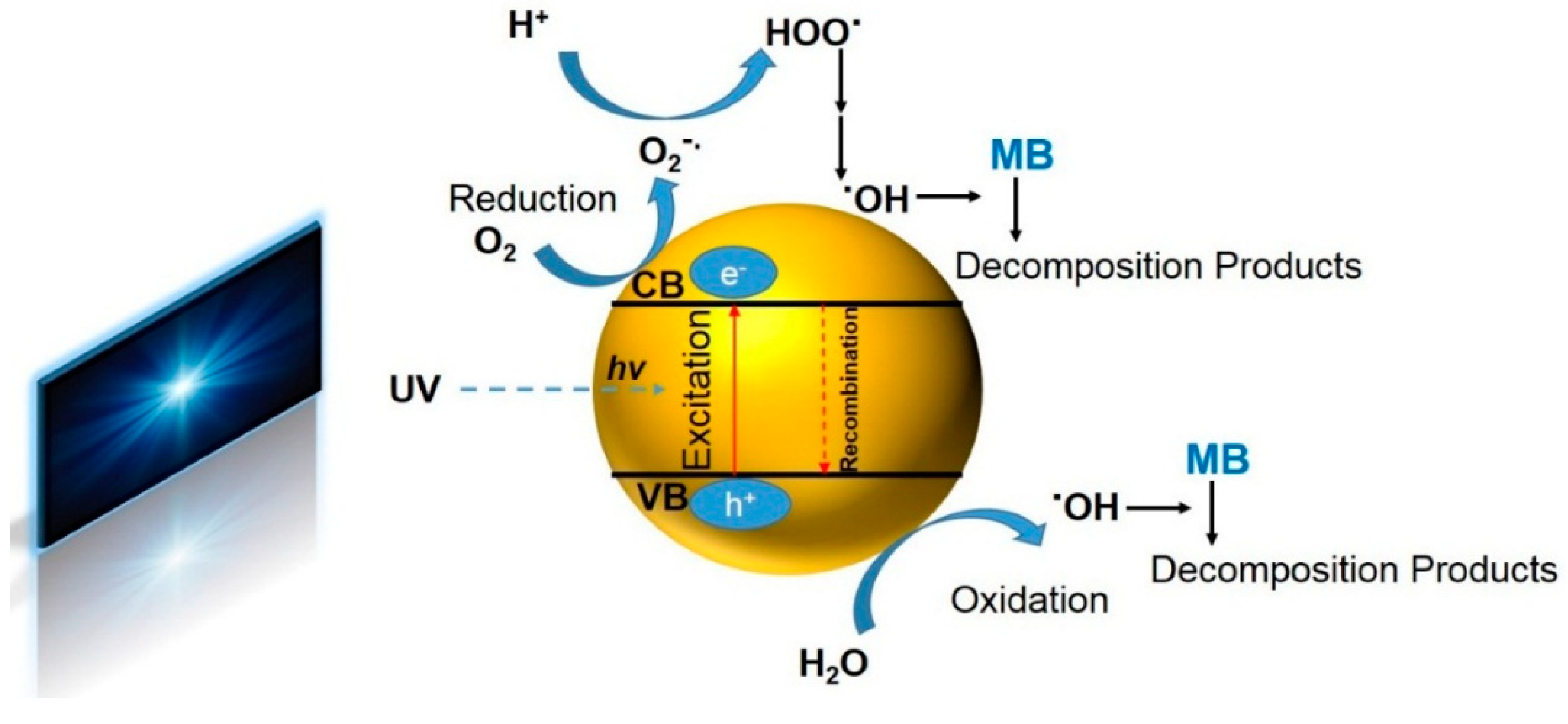
- TiO2 receives an efficient photon energy (hv ≥ 3.2 eV).
- (2)
- Oxygen ionosorption takes place whereby oxygen is reduced, i.e., oxygen’s oxidation degree declines from 0 to −1/2.
- (3)
- Hydroxide ions are neutralized by photoholes, and thereby OH• radicals are formed.
- (4)
- Protons neutralize .
- (5)
- Temporarily, H2O2 is produced, and the dismutation of oxygen occurs.
- (6)
- H2O2 is dissociated, and oxygen is reduced for the second time.
- (7)
- The MB molecules (or any other organic material in the adjacent of TiO2; R) are oxidized through consecutive attacks by radicals.
- (8)
- The MB molecules (R) can be directly oxidized by the reaction with holes.
4. Conclusions
Author Contributions
Funding
Conflicts of Interest
References
- Yang, L.; Wang, Z.; Zhang, J. Zeolite imidazolate framework hybrid nanofiltration (nf) membranes with enhanced permselectivity for dye removal. J. Membrane Sci. 2017, 532, 76–86. [Google Scholar] [CrossRef]
- Homaeigohar, S.; Zillohu, A.U.; Abdelaziz, R.; Hedayati, M.K.; Elbahri, M. A novel nanohybrid nanofibrous adsorbent for water purification from dye pollutants. Materials 2016, 9, 848. [Google Scholar] [CrossRef] [PubMed]
- Saravanan, R.; Karthikeyan, N.; Gupta, V.K.; Thirumal, E.; Thangadurai, P.; Narayanan, V.; Stephen, A. Zno/ag nanocomposite: An efficient catalyst for degradation studies of textile effluents under visible light. Mat. Sci. Eng. C 2013, 33, 2235–2244. [Google Scholar] [CrossRef] [PubMed]
- Janaki, V.; Oh, B.-T.; Shanthi, K.; Lee, K.-J.; Ramasamy, A.K.; Kamala-Kannan, S. Polyaniline/chitosan composite: An eco-friendly polymer for enhanced removal of dyes from aqueous solution. Synth. Met. 2012, 162, 974–980. [Google Scholar] [CrossRef]
- Raghuvanshi, S.; Singh, R.; Kaushik, C.; Raghav, A. Kinetics study of methylene blue dye bioadsorption on baggase. Appl. Ecol. Environ. Res. 2004, 2, 35–43. [Google Scholar] [CrossRef]
- Konstantinou, I.K.; Albanis, T.A. TiO2-assisted photocatalytic degradation of azo dyes in aqueous solution: Kinetic and mechanistic investigations: A review. Appl. Catal. B-Environ. 2004, 49, 1–14. [Google Scholar] [CrossRef]
- Homaeigohar, S.; Elbahri, M. An amphiphilic, graphitic buckypaper capturing enzyme biomolecules from water. Water 2019, 11, 2. [Google Scholar] [CrossRef]
- Dong, F.; Guo, S.; Wang, H.; Li, X.; Wu, Z. Enhancement of the visible light photocatalytic activity of c-doped TiO2 nanomaterials prepared by a green synthetic approach. J. Phys. Chem. C 2011, 115, 13285–13292. [Google Scholar] [CrossRef]
- Dong, H.; Guan, X.; Wang, D.; Li, C.; Yang, X.; Dou, X. A novel application of H2O2–Fe (ii) process for arsenate removal from synthetic acid mine drainage (amd) water. Chemosphere 2011, 85, 1115–1121. [Google Scholar] [CrossRef]
- Oller, I.; Malato, S.; Sánchez-Pérez, J. Combination of advanced oxidation processes and biological treatments for wastewater decontamination—A review. Sci. Total Environ. 2011, 409, 4141–4166. [Google Scholar] [CrossRef]
- Zhou, Y.; Tang, L.; Zeng, G.; Chen, J.; Cai, Y.; Zhang, Y.; Yang, G.; Liu, Y.; Zhang, C.; Tang, W. Mesoporous carbon nitride based biosensor for highly sensitive and selective analysis of phenol and catechol in compost bioremediation. Biosens. Bioelectron. 2014, 61, 519–525. [Google Scholar] [CrossRef] [PubMed]
- Dong, H.; Zeng, G.; Tang, L.; Fan, C.; Zhang, C.; He, X.; He, Y. An overview on limitations of TiO2-based particles for photocatalytic degradation of organic pollutants and the corresponding countermeasures. Water Res. 2015, 79, 128–146. [Google Scholar] [CrossRef] [PubMed]
- Panthi, G.; Park, M.; Kim, H.-Y.; Lee, S.-Y.; Park, S.-J. Electrospun zno hybrid nanofibers for photodegradation of wastewater containing organic dyes: A review. J. Ind. Eng. Chem. 2015, 21, 26–35. [Google Scholar] [CrossRef]
- Liu, Y.; Zhou, L.; Hu, Y.; Guo, C.; Qian, H.; Zhang, F.; Lou, X.W.D. Magnetic-field induced formation of 1D Fe3O4/C/CdS coaxial nanochains as highly efficient and reusable photocatalysts for water treatment. J. Mater. Chem. 2011, 21, 18359–18364. [Google Scholar] [CrossRef]
- Seema, H.; Kemp, K.C.; Chandra, V.; Kim, K.S. Graphene–SnO2 composites for highly efficient photocatalytic degradation of methylene blue under sunlight. Nanotechnology 2012, 23, 355705. [Google Scholar] [CrossRef] [PubMed]
- Nishimoto, S.; Mano, T.; Kameshima, Y.; Miyake, M. Photocatalytic water treatment over WO3 under visible light irradiation combined with ozonation. Chem. Phys. Lett. 2010, 500, 86–89. [Google Scholar] [CrossRef]
- Nakano, K.; Obuchi, E.; Takagi, S.; Yamamoto, R.; Tanizaki, T.; Taketomi, M.; Eguchi, M.; Ichida, K.; Suzuki, M.; Hashimoto, A. Photocatalytic treatment of water containing dinitrophenol and city water over TiO2/SiO2. Sep. Purif. Technol. 2004, 34, 67–72. [Google Scholar] [CrossRef]
- Daneshvar, N.; Salari, D.; Khataee, A. Photocatalytic degradation of azo dye acid red 14 in water on ZnO as an alternative catalyst to TiO2. J. Photochem. Photobiol. A-Chem. 2004, 162, 317–322. [Google Scholar] [CrossRef]
- Cao, S.-W.; Zhu, Y.-J. Hierarchically nanostructured α-Fe2O3 hollow spheres: Preparation, growth mechanism, photocatalytic property, and application in water treatment. J. Phys. Chem. C 2008, 112, 6253–6257. [Google Scholar] [CrossRef]
- Homaeigohar, S.; Davoudpour, Y.; Habibi, Y.; Elbahri, M. The electrospun ceramic hollow nanofibers. Nanomaterials 2017, 7, 383. [Google Scholar] [CrossRef] [PubMed]
- Carp, O.; Huisman, C.L.; Reller, A. Photoinduced reactivity of titanium dioxide. Prog. Solid State Chem. 2004, 32, 33–177. [Google Scholar] [CrossRef]
- Fujishima, A.; Rao, T.N.; Tryk, D.A. Titanium dioxide photocatalysis. J. Photochem. Photobiol. C-Photochem. Rev. 2000, 1, 1–21. [Google Scholar] [CrossRef]
- Chong, M.N.; Jin, B.; Chow, C.W.; Saint, C. Recent developments in photocatalytic water treatment technology: A review. Water Res. 2010, 44, 2997–3027. [Google Scholar] [CrossRef] [PubMed]
- Bhattacharyya, A.; Kawi, S.; Ray, M. Photocatalytic degradation of orange ii by TiO2 catalysts supported on adsorbents. Catal. Today 2004, 98, 431–439. [Google Scholar] [CrossRef]
- Gao, B.; Yap, P.S.; Lim, T.M.; Lim, T.-T. Adsorption-photocatalytic degradation of acid red 88 by supported TiO2: Effect of activated carbon support and aqueous anions. Chem. Eng. J. 2011, 171, 1098–1107. [Google Scholar] [CrossRef]
- Cui, J.; He, T.; Zhang, X. Synthesis of Fe3O4@SiO2@Ption–TiO2 hybrid composites with high efficient UV–visible light photoactivity. Catal. Commun. 2013, 40, 66–70. [Google Scholar] [CrossRef]
- Meng, X.; Luo, N.; Cao, S.; Zhang, S.; Yang, M.; Hu, X. In-situ growth of titania nanoparticles in electrospun polymer nanofibers at low temperature. Mater. Lett. 2009, 63, 1401–1403. [Google Scholar] [CrossRef]
- Homaeigohar, S.S.; Elbahri, M. Novel compaction resistant and ductile nanocomposite nanofibrous microfiltration membranes. J. Colloid Interf. Sci. 2012, 372, 6–15. [Google Scholar] [CrossRef]
- Khrenov, V.; Klapper, M.; Koch, M.; Müllen, K. Surface functionalized zno particles designed for the use in transparent nanocomposites. Macromol. Chem. Phys. 2005, 206, 95–101. [Google Scholar] [CrossRef]
- Zeng, C.; Lee, L.J. Poly (methyl methacrylate) and polystyrene/clay nanocomposites prepared by in-situ polymerization. Macromolecules 2001, 34, 4098–4103. [Google Scholar] [CrossRef]
- Reynaud, E.; Jouen, T.; Gauthier, C.; Vigier, G.; Varlet, J. Nanofillers in polymeric matrix: A study on silica reinforced PA6. Polymer 2001, 42, 8759–8768. [Google Scholar] [CrossRef]
- Demir, M.M.; Castignolles, P.; Akbey, Ü.; Wegner, G. In-situ bulk polymerization of dilute particle/mma dispersions. Macromolecules 2007, 40, 4190–4198. [Google Scholar] [CrossRef]
- Mikrajuddin; Lenggoro, I.W.; Okuyama, K.; Shi, F. Luminescent polymer electrolytes prepared by growing zno nanoparticles in the matrix of polyethylene glycol. J. Electrochem. Soc. 2002, 149, 107–112. [Google Scholar] [CrossRef]
- Alberti, A.; Bongiorno, C.; Pellegrino, G.; Sanzaro, S.; Smecca, E.; Condorelli, G.; Giuffrida, A.; Cicala, G.; Latteri, A.; Ognibene, G. Low temperature sputtered TiO2 nano sheaths on electrospun pes fibers as high porosity photoactive material. RSC Adv. 2015, 5, 73444–73450. [Google Scholar] [CrossRef]
- Homaeigohar, S.S.; Buhr, K.; Ebert, K. Polyethersulfone electrospun nanofibrous composite membrane for liquid filtration. J. Membrane Sci. 2010, 365, 68–77. [Google Scholar] [CrossRef]
- Pontié, M.; Chasseray, X.; Lemordant, D.; Laine, J. The streaming potential method for the characterization of ultrafiltration organic membranes and the control of cleaning treatments. J. Membrane Sci. 1997, 129, 125–133. [Google Scholar] [CrossRef]
- Ricq, L.; Pierre, A.; Bayle, S.; Reggiani, J.-C. Electrokinetic characterization of polyethersulfone uf membranes. Desalination 1997, 109, 253–261. [Google Scholar] [CrossRef]
- Daels, N.; Radoicic, M.; Radetic, M.; Van Hulle, S.W.H.; De Clerck, K. Functionalisation of electrospun polymer nanofibre membranes with TiO2 nanoparticles in view of dissolved organic matter photodegradation. Sep. Purif. Technol. 2014, 133, 282–290. [Google Scholar] [CrossRef]
- Homaeigohar, S.S.; Mahdavi, H.; Elbahri, M. Extraordinarily water permeable sol gel formed nanocomposite nanofibrous membranes. J. Colloid Interf. Sci. 2012, 366, 51–56. [Google Scholar] [CrossRef] [PubMed]
- Demirci, S.; Dikici, T.; Yurddaskal, M.; Gultekin, S.; Toparli, M.; Celik, E. Synthesis and characterization of ag doped TiO2 heterojunction films and their photocatalytic performances. Appl. Surf. Sci. 2016, 390, 591–601. [Google Scholar] [CrossRef]
- Elbahri, M.; Homaeigohar, S.; Dai, T.; Abdelaziz, R.; Khalil, R.; Zillohu, A.U. Smart metal-polymer bionanocomposites as omnidirectional plasmonic black absorbers formed by nanofluid filtration. Adv. Funct. Mater. 2012, 22, 4771–4777. [Google Scholar] [CrossRef]
- Homaeigohar, S.; Dai, T.; Elbahri, M. Biofunctionalized nanofibrous membranes as super separators of protein and enzyme from water. J. Colloid Interf. Sci. 2013, 406, 86–93. [Google Scholar] [CrossRef] [PubMed]
- Homaeigohar, S.; Disci-Zayed, D.; Dai, T.; Elbahri, M. Biofunctionalized nanofibrous membranes mimicking carnivorous plants. Bioinspir. Biomim. Nan. 2013, 2, 186–193. [Google Scholar] [CrossRef]
- Homaeigohar, S.; Strunskus, T.; Strobel, J.; Kienle, L.; Elbahri, M. A flexible oxygenated carbographite nanofilamentous buckypaper as an amphiphilic membrane. Adv. Mater. Interf. 2018, 5, 1800001. [Google Scholar] [CrossRef]
- Li, D.; Zhu, Q.; Han, C.; Yang, Y.; Jiang, W.; Zhang, Z. Photocatalytic degradation of recalcitrant organic pollutants in water using a novel cylindrical multi-column photoreactor packed with TiO2-coated silica gel beads. J. Hazard. Mater. 2015, 285, 398–408. [Google Scholar] [CrossRef] [PubMed]
- Namasivayam, C.; Kavitha, D. Removal of congo red from water by adsorption onto activated carbon prepared from coir pith, an agricultural solid waste. Dyes Pigments 2002, 54, 47–58. [Google Scholar] [CrossRef]
- Acemioğlu, B. Adsorption of congo red from aqueous solution onto calcium-rich fly ash. J. Colloid Interf. Sci. 2004, 274, 371–379. [Google Scholar] [CrossRef] [PubMed]
- Fong, H.; Chun, I.; Reneker, D. Beaded nanofibers formed during electrospinning. Polymer 1999, 40, 4585–4592. [Google Scholar] [CrossRef]
- Zhang, H.; Banfield, J.F. Kinetics of crystallization and crystal growth of nanocrystalline anatase in nanometer-sized amorphous titania. Chem. Mater. 2002, 14, 4145–4154. [Google Scholar] [CrossRef]
- Rico-Oller, B.; Boudjemaa, A.; Bahruji, H.; Kebir, M.; Prashar, S.; Bachari, K.; Fajardo, M.; Gómez-Ruiz, S. Photodegradation of organic pollutants in water and green hydrogen production via methanol photoreforming of doped titanium oxide nanoparticles. Sci. Total Environ. 2016, 563–564, 921–932. [Google Scholar] [CrossRef]
- Yu, J.; Yu, H.; Cheng, B.; Trapalis, C. Effects of calcination temperature on the microstructures and photocatalytic activity of titanate nanotubes. J. Mol. Catal. A-Chem. 2006, 249, 135–142. [Google Scholar] [CrossRef]
- Belfer, S.; Fainchtain, R.; Purinson, Y.; Kedem, O. Surface characterization by ftir-atr spectroscopy of polyethersulfone membranes-unmodified, modified and protein fouled. J. Membrane Sci. 2000, 172, 113–124. [Google Scholar] [CrossRef]
- Zhang, L.; Liu, P.; Su, Z. Preparation of pani–TiO2 nanocomposites and their solid-phase photocatalytic degradation. Polym. Degrad. Stabil. 2006, 91, 2213–2219. [Google Scholar] [CrossRef]
- Luo, M.-L.; Tang, W.; Zhao, J.-Q.; Pu, C.-S. Hydrophilic modification of poly (ether sulfone) used TiO2 nanoparticles by a sol–gel process. J. Mater. Proc. Technol. 2006, 172, 431–436. [Google Scholar] [CrossRef]
- Stachewicz, U.; Bailey, R.J.; Zhang, H.; Stone, C.A.; Willis, C.R.; Barber, A.H. Wetting hierarchy in oleophobic 3D electrospun nanofiber networks. ACS Appl. Mater. Inter. 2015, 7, 16645–16652. [Google Scholar] [CrossRef] [PubMed]
- Xu, Q.F.; Liu, Y.; Lin, F.-J.; Mondal, B.; Lyons, A.M. Superhydrophobic TiO2–polymer nanocomposite surface with UV-induced reversible wettability and self-cleaning properties. ACS Appl. Mater. Inter. 2013, 5, 8915–8924. [Google Scholar] [CrossRef] [PubMed]
- Cho, S.; Choi, W. Solid-phase photocatalytic degradation of pvc–TiO2 polymer composites. J. Photochem. Photobiol. A-Chem. 2001, 143, 221–228. [Google Scholar] [CrossRef]
- Homaeigohar, S.S.; Sadi, A.Y.; Javadpour, J.; Khavandi, A. The effect of reinforcement volume fraction and particle size on the mechanical properties of β-tricalcium phosphate–high density polyethylene composites. J. Eur. Ceram. Soc. 2006, 26, 273–278. [Google Scholar] [CrossRef]
- Carotenuto, G.; Valente, M.; Sciumè, G.; Valente, T.; Pepe, G.; Ruotolo, A.; Nicolais, L. Preparation and characterization of transparent/conductive nano-composites films. J. Mater. Sci. 2006, 41, 5587–5592. [Google Scholar] [CrossRef]
- Kamrannejad, M.M.; Hasanzadeh, A.; Nosoudi, N.; Mai, L.; Babaluo, A.A. Photocatalytic degradation of polypropylene/TiO2 nano-composites. Mat. Res. 2014, 17, 1039–1046. [Google Scholar] [CrossRef]
- Rivaton, A.; Gardette, J.L. Photodegradation of polyethersulfone and polysulfone. Polym. Degrad. Stabil. 1999, 66, 385–403. [Google Scholar] [CrossRef]
- Houas, A.; Lachheb, H.; Ksibi, M.; Elaloui, E.; Guillard, C.; Herrmann, J.-M. Photocatalytic degradation pathway of methylene blue in water. Appl. Catal. B-Environ. 2001, 31, 145–157. [Google Scholar] [CrossRef]
- Lamb, A.C.M.; Grieser, F.; Healy, T.W. The adsorption of uranium (vi) onto colloidal TiO2, SiO2 and carbon black. Colloids Surf. A 2016, 499, 156–162. [Google Scholar] [CrossRef]
- Ho, Y.-S.; McKay, G. Pseudo-second order model for sorption processes. Proc. Biochem. 1999, 34, 451–465. [Google Scholar] [CrossRef]


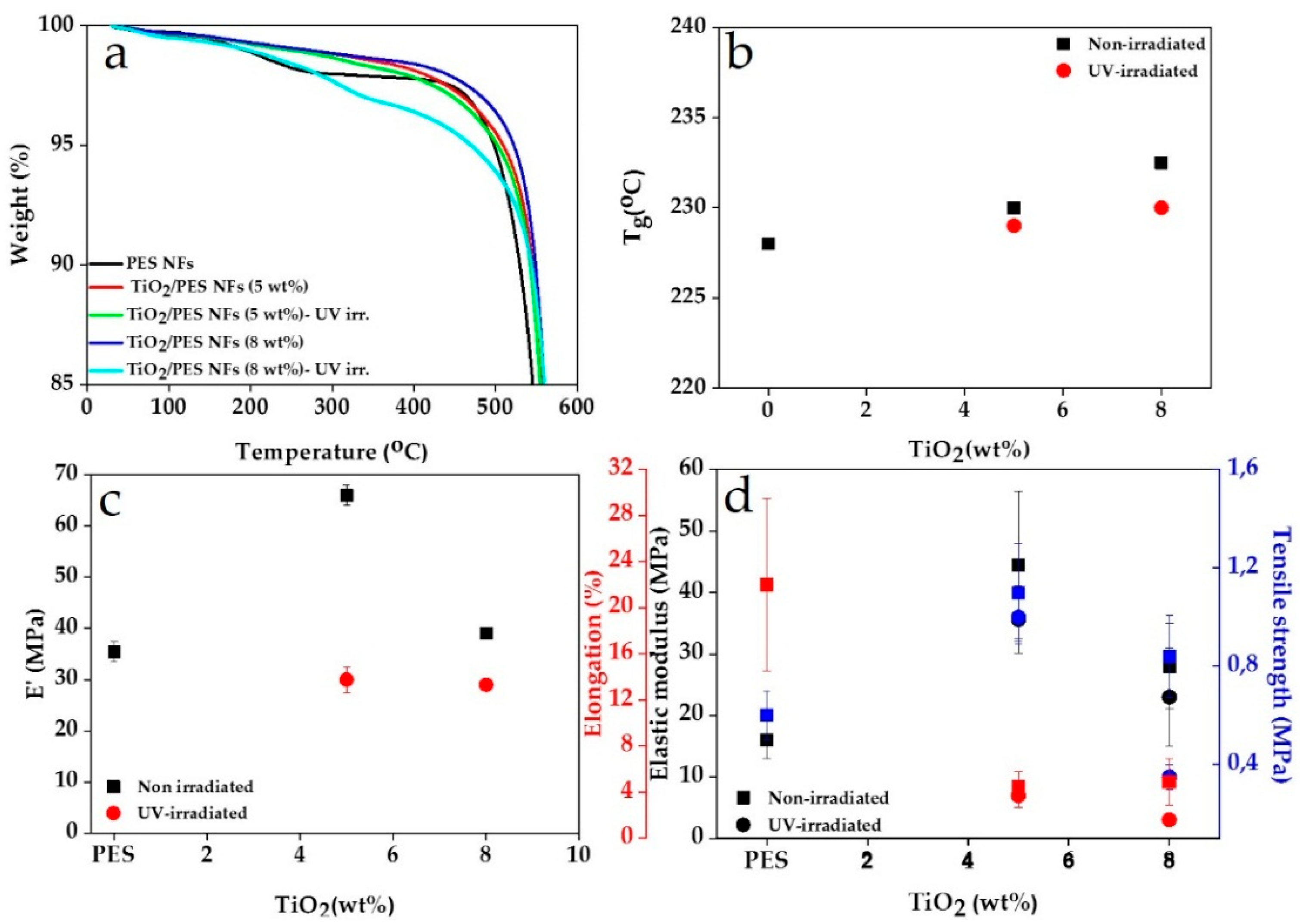
| Filling Factor | UV-Irradiation | Td (°C) |
|---|---|---|
| 0 wt.% TiO2 | No | 498 |
| 5 wt.% TiO2 | No | 509 |
| 5 wt.% TiO2 | Yes | 502 |
| 8 wt.% TiO2 | No | 522 |
| 8 wt.% TiO2 | Yes | 470 |
| 4 mg·L−1 | 4 mg·L−1 | 7 mg·L−1 | 7 mg·L−1 | 9 mg·L−1 | 9 mg·L−1 | |
|---|---|---|---|---|---|---|
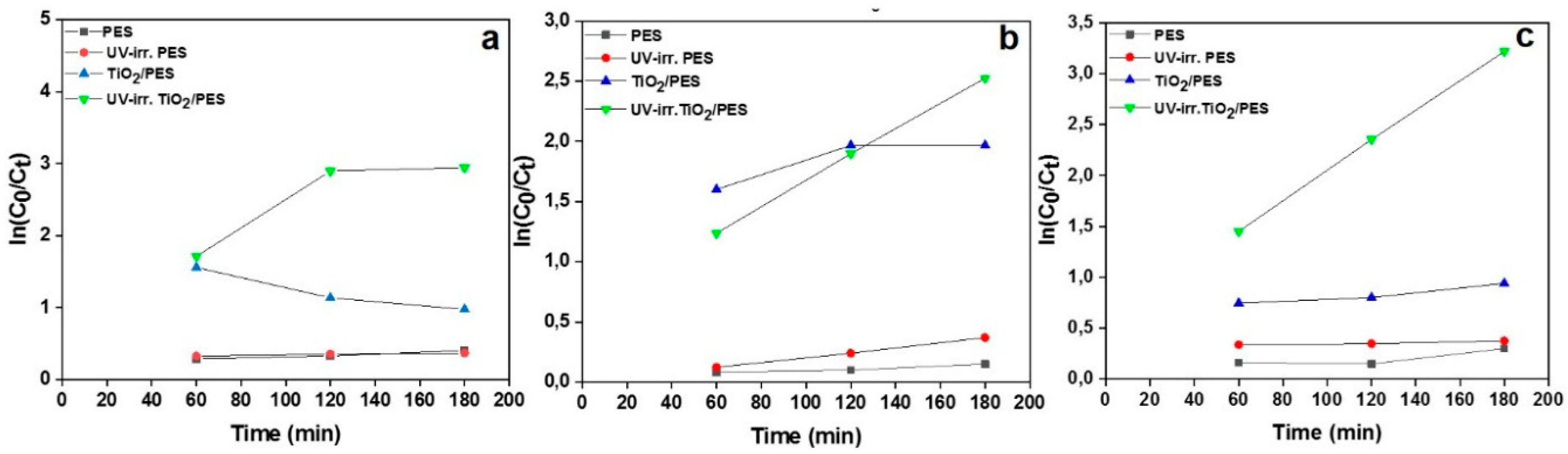
| Kapp (min−1) | R2 | Kapp (min−1) | R2 | Kapp (min−1) | R2 | |
| PES | 0.001 | 0.976 | 0.0005 | 0.923 | 0.0011 | 0.685 |
| UV-irr. PES | 0.0003 | 0.970 | 0.00204 | 0.998 | 0.0003 | 0.930 |
| TiO2/PES | −0.0048 | 0.936 | 0.0035 | 0.75 | 0.0016 | 0.937 |
| UV-irr. TiO2/PES | 0.0102 | 0.777 | 0.01073 | 0.999 | 0.0147 | 0.999 |
| 4 mg·L−1 | 4 mg·L−1 | 4 mg·L−1 | 7 mg·L−1 | 7 mg·L−1 | 7 mg·L−1 | 9 mg·L−1 | 9 mg·L−1 | 9 mg·L−1 | |
|---|---|---|---|---|---|---|---|---|---|
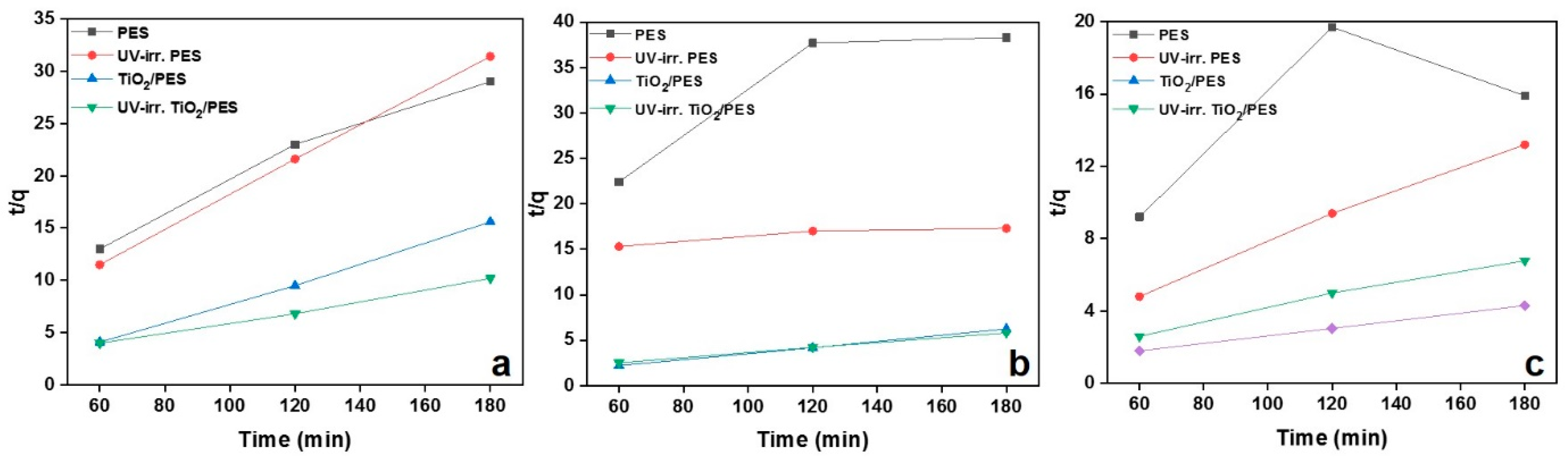
| K2 (min−1) | qe (mg·g−1) | R2 | K2 (min−1) | qe (mg·g−1) | R2 | K2 (min−1) | qe (mg·g−1) | R2 | |
| PES | 0.003 | 7.52 | 0.979 | 0.001 | 7.57 | 0.778 | 0.0003 | 18.18 | 0.397 |
| UV-irr. PES | 0.004 | 6.06 | 0.999 | 0.00002 | 60.24 | 0.859 | 0.0066 | 14.28 | 0.996 |
| TiO2/PES | 0.005 | 10.43 | 0.998 | 0.007 | 30.30 | 0.999 | 0.0018 | 29.41 | 0.992 |
| UV-irr. TiO2/PES | 0.003 | 19.37 | 0.996 | 0.00086 | 36.36 | 0.999 | 0.0007 | 50 | 0.999 |
© 2019 by the authors. Licensee MDPI, Basel, Switzerland. This article is an open access article distributed under the terms and conditions of the Creative Commons Attribution (CC BY) license (http://creativecommons.org/licenses/by/4.0/).
Share and Cite
Homaeigohar, S.; Botcha, N.K.; Zarie, E.S.; Elbahri, M. Ups and Downs of Water Photodecolorization by Nanocomposite Polymer Nanofibers. Nanomaterials 2019, 9, 250. https://doi.org/10.3390/nano9020250
Homaeigohar S, Botcha NK, Zarie ES, Elbahri M. Ups and Downs of Water Photodecolorization by Nanocomposite Polymer Nanofibers. Nanomaterials. 2019; 9(2):250. https://doi.org/10.3390/nano9020250
Chicago/Turabian StyleHomaeigohar, Shahin, Niharika Krishna Botcha, Eman. S. Zarie, and Mady Elbahri. 2019. "Ups and Downs of Water Photodecolorization by Nanocomposite Polymer Nanofibers" Nanomaterials 9, no. 2: 250. https://doi.org/10.3390/nano9020250
APA StyleHomaeigohar, S., Botcha, N. K., Zarie, E. S., & Elbahri, M. (2019). Ups and Downs of Water Photodecolorization by Nanocomposite Polymer Nanofibers. Nanomaterials, 9(2), 250. https://doi.org/10.3390/nano9020250