3. Results
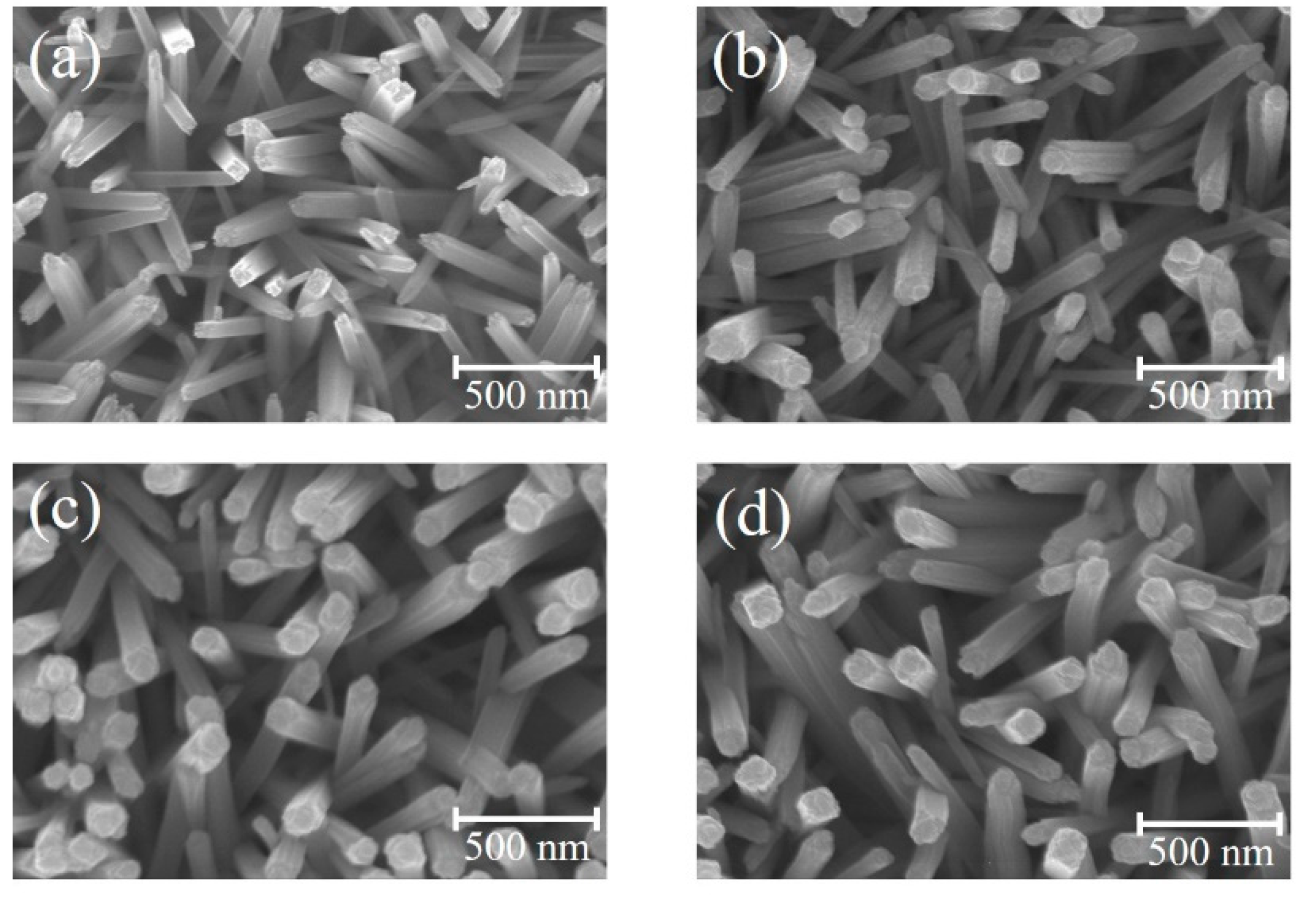
Figure 1a–d show SEM images of the TiO
2 nanorods before and after coating ZFO shell layers with various thicknesses.
Figure 1a reveals the presence of many cross-sectional square-shaped TiO
2 nanorods with an average diameter of 75 nm. Moreover, the TiO
2 nanorods had an average length of approximately 1.1 um from the cross-sectional image (not shown herein). The smooth surface of the TiO
2 nanorods can be observed. Notably,
Figure 1b–d show the morphologies of the TiO
2 nanorods after coating ZFO shell layers with various deposition durations is similar to that as shown in
Figure 1a. This reveals that the coverage layer thickness of ZFO on the surfaces of the TiO
2 nanorods are thin and resulted in the fact that the TiO
2–ZFO composite nanorods still maintained their free-standing feature over the substrates. After the sputtering deposition of ZFO onto the surfaces of TiO
2 nanorods, the surface feature of TiO
2 nanorods changed from the smooth surface to the surface composed of many bulges on it. The ZFO was homogeneously loaded onto the surface of TiO
2 nanorods forming a composite structure. The diameter variation among the various TiO
2–ZFO composite nanorods with various ZFO sputtering durations was not clearly distinguished from the SEM images herein; this might be associated with the nano-scaled ZFO shell layers on the TiO
2 surface. To further confirm the ZFO shell layer thickness variation among the various TiO
2–ZFO samples, TEM investigations were further conducted in this study.
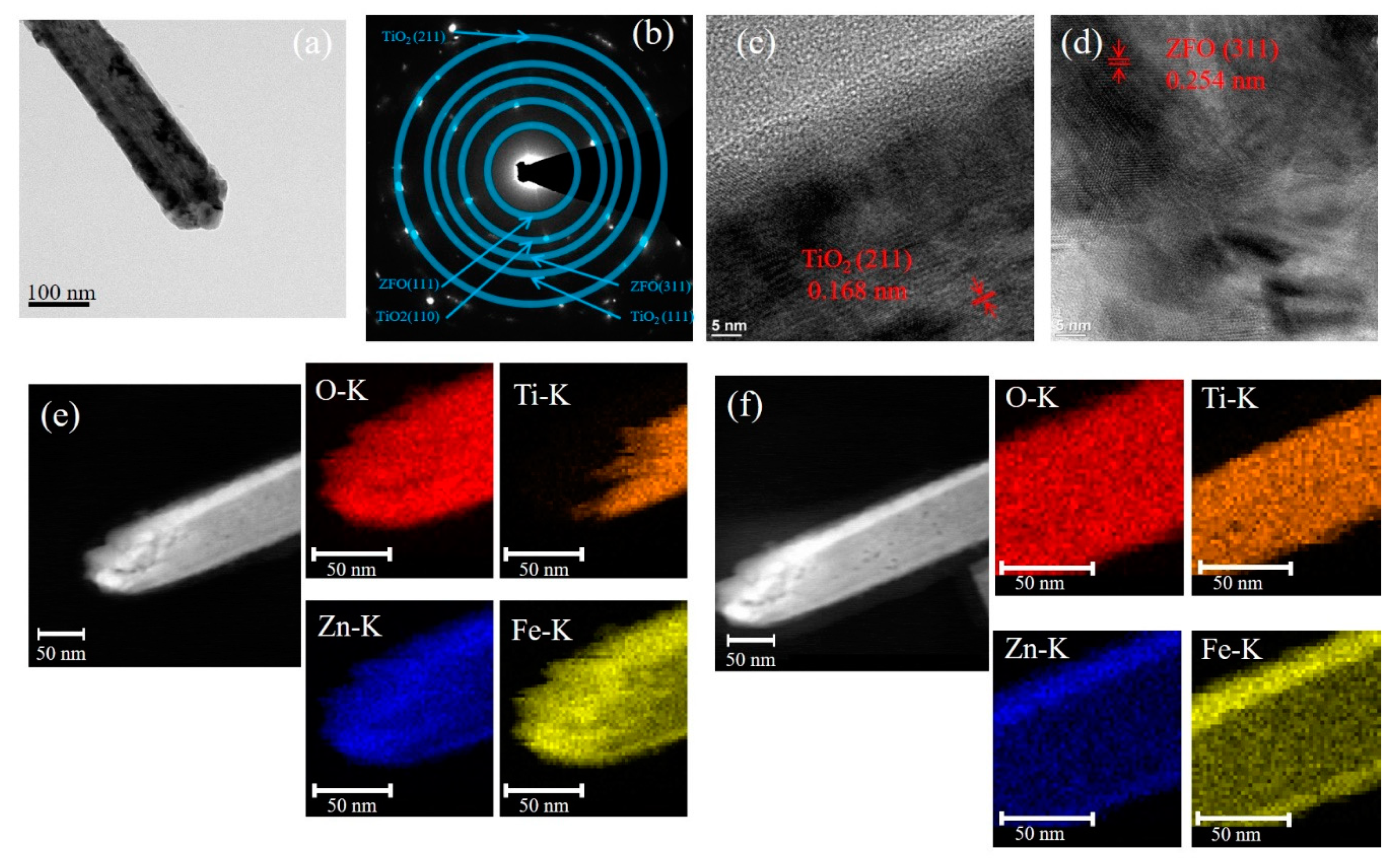
Figure 2a presents a representative low-magnification TEM micrograph of the TiO
2–ZFO-1 composite nanorod. The selected area electron diffraction (SAED) pattern taken from several composite nanorods was shown in
Figure 2b and it exhibited clear diffraction spots arranged in circles. The centric SAED pattern indicates the co-existence of the ZFO and TiO
2 phases. Moreover, the TiO
2–ZFO-1 composite nanorods were in polycrystalline feature. The high-resolution TEM (HRTEM) micrographs from the head and lateral regions of the composite nanorod in
Figure 2a are displayed in
Figure 2c,d, respectively. The lattice spacing of 0.168 nm for the inner region and 0.254 nm for the outer region of the composite nanorod in the HRTEM images corresponded to the crystallographic plane of (211) for the rutile TiO
2 and the (311) plane of the cubic ZFO, respectively. Notably, the head region of the composite nanorod consisted of several distinct, large ZFO crystallites and the lateral region of the composite nanorod composed of ZFO in a thin-layered structure. The elemental mapping images of Ti, O, Zn, and Fe from the head and body regions of the TiO
2–ZFO-1nanorod are demonstrated in
Figure 2e,f, respectively. The Ti element was located inside the composite nanorod, while the Zn and Fe elements enclose the rod body, which is definitive proof for the successful synthesis of the core-shell TiO
2–ZFO nanorod. Notably, the thickness of the ZFO at the coverage region of the composite nanorod’s head is markedly thicker than that at the lateral region of the composite nanorod. The elemental dispersive region size of Zn and Fe at the head region of the composite nanorod is approximately 43 nm on average, and at the lateral region of the composite rod it is only 15 nm. This is due to the fact that the head region of free-standing TiO
2 nanorods will encounter more sputtering deposited ZFO adatoms than those of the lateral region of the nanorods because of the one-dimensional geometry effect of the TiO
2 nanorods. The elemental mapping analysis demonstrated that the ZFO was continuously decorated on the TiO
2 nanorod.
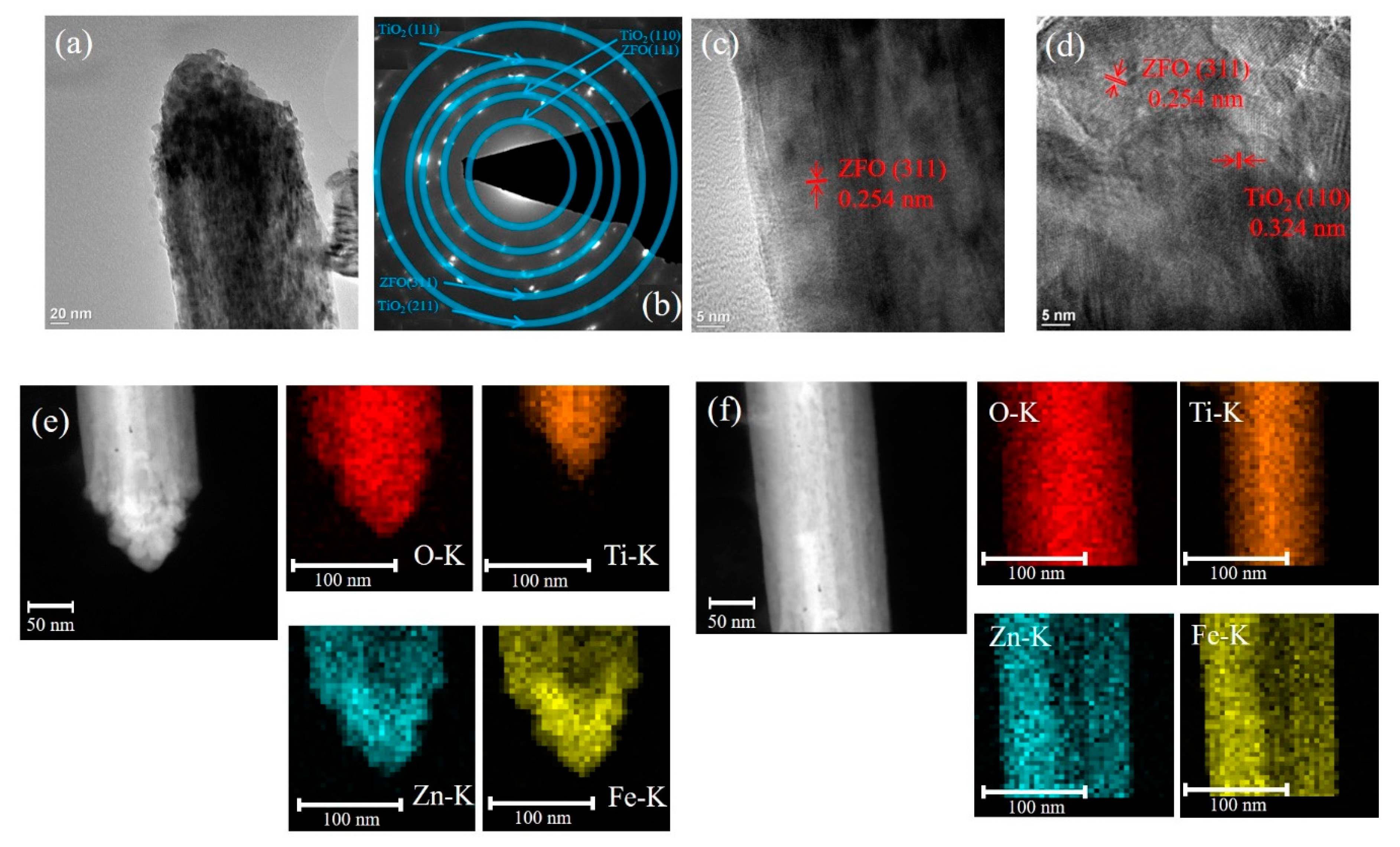
Figure 3a presents the low-magnification TEM image of the single TiO
2–ZFO-2 nanorod.
Figure 3b demonstrates the SAED pattern taken from several TiO
2–ZFO-2 composite nanorods. The clear diffraction spots in centric rings reveals crystalline feature of the TiO
2–ZFO composite nanorods. The HR images in
Figure 3c,d demonstrates the local lattice fringes of the ZFO and TiO
2 structures taken from the head and lateral regions of the composite nanorod. Similar to the analysis in
Figure 2e,f, the coverage thickness of ZFO crystallite is different in the head and body regions of the composite nanorod. The elemental dispersive region size of Zn and Fe at the head region of the TiO
2–ZFO-2 composite nanorod was approximately 63 nm and at the lateral region of the composite nanorod it was 30 nm (
Figure 3e,f).
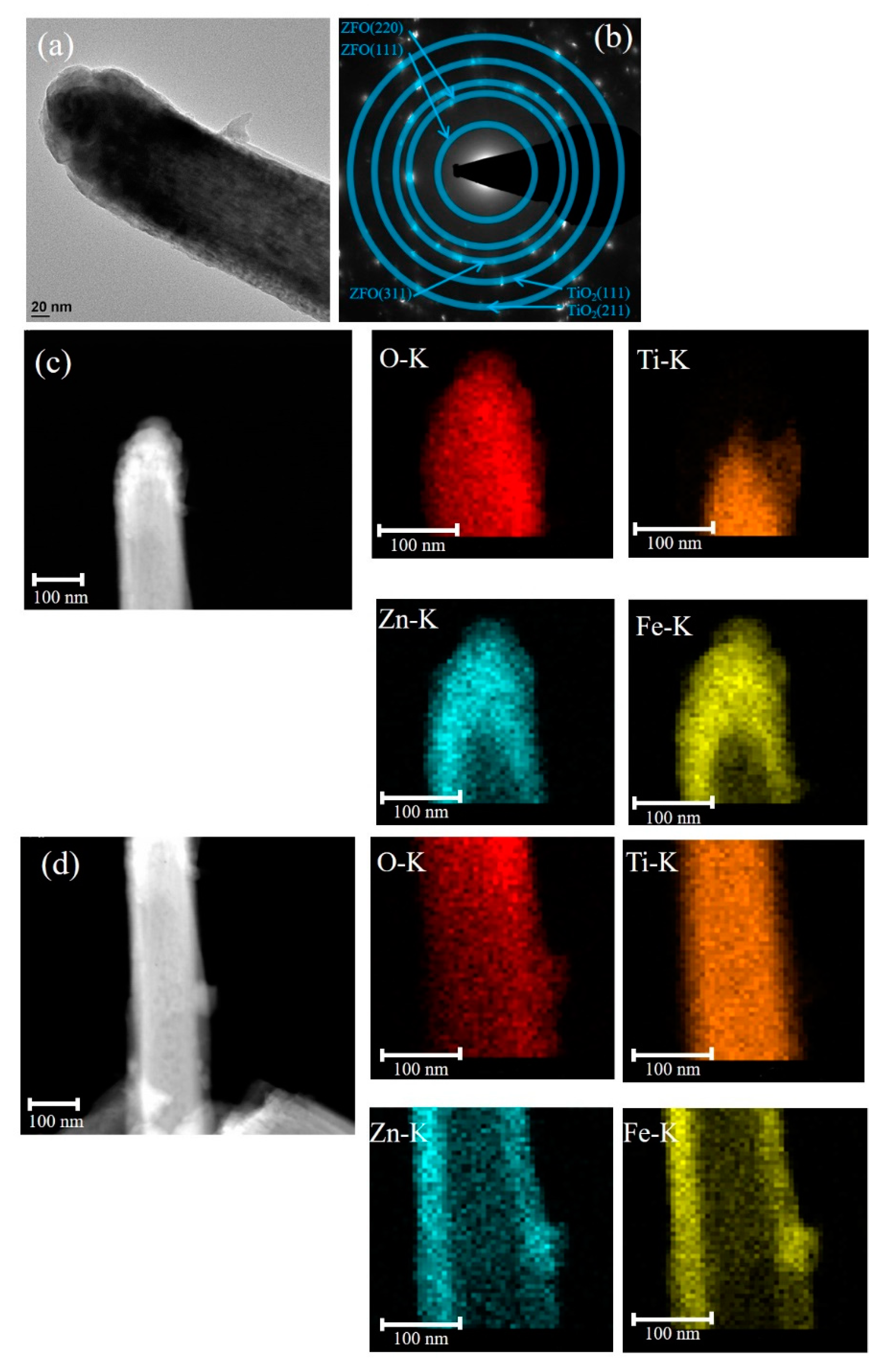
The low-magnification TEM image of the TiO
2–ZFO-3 nanorod is shown in
Figure 4a. The morphology of the head region of the composite nanorod became rounder in comparison with the other composite nanorods prepared at a shorter ZFO sputtering duration. Furthermore, the SAED pattern with distinct spots arranged in centric rings in
Figure 4b exhibits the crystalline feature of the TiO
2–ZFO-3 composite nanorods prepared with the ZFO sputtering duration of 60 min. Notably, the clear local HR images taken from
Figure 4a are not available herein because a thicker ZFO covered the TiO
2 nanorod. The elemental dispersive region size of the Zn and Fe at the head region of the composite nanorod was evaluated to be approximately 97 nm on average and that at the lateral region of the composite, the nanorod was 45 nm from the elemental mapping images in
Figure 4c,d. Notably, the increment of the ZFO thickness in the head region was substantially larger than that in the lateral region of the composite nanorod for the prolonged sputtering deposition of ZFO onto the free-standing TiO
2 nanorods in this study. Nerveless, the ZFO shell layer was fully covered onto the TiO
2 to form a core-shell composite structure with various ZFO sputtering durations herein.
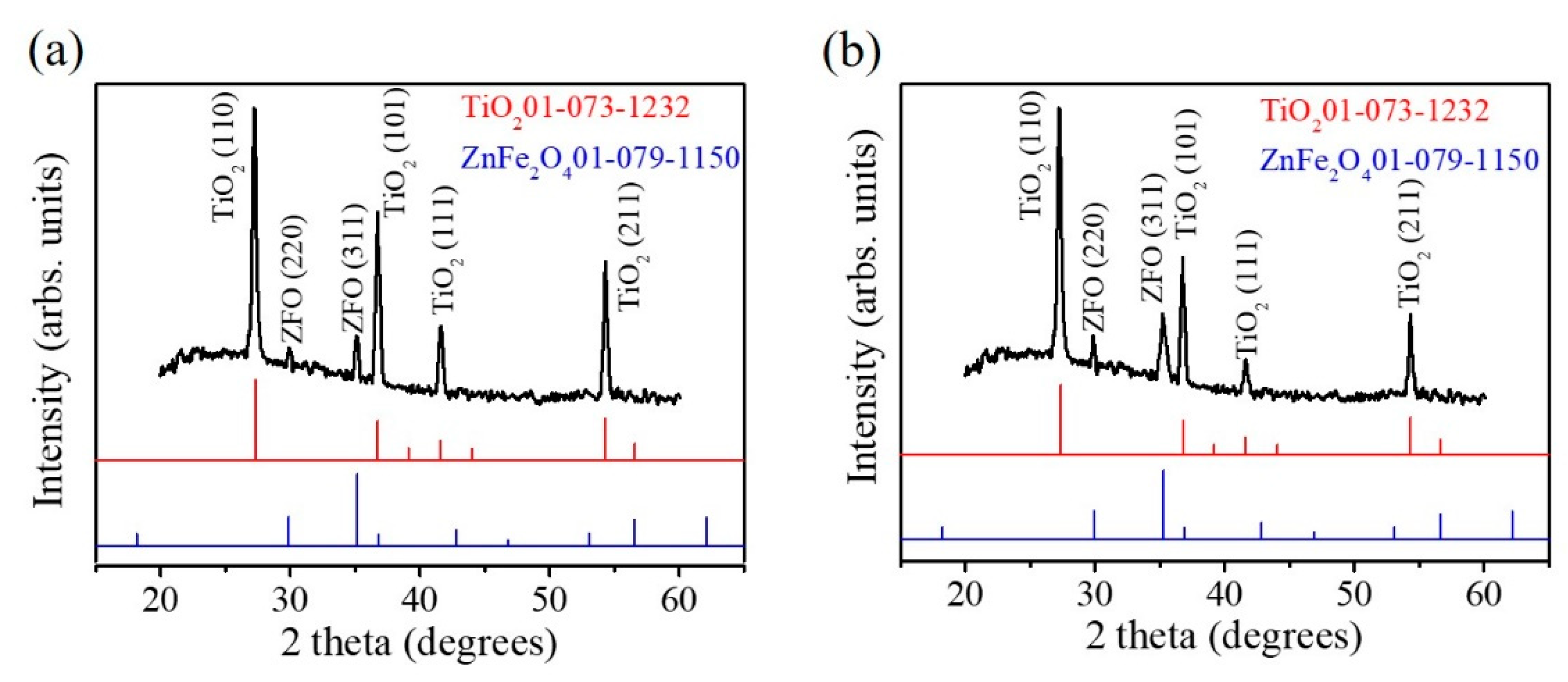
The XRD patterns of the TiO
2–ZFO-2 and TiO
2–ZFO-3 nanorods are shown in
Figure 5a,b to demonstrate the crystal structure of the TiO
2–ZFO composite nanorods. Notably, the XRD pattern of the TiO
2–ZFO-1 nanorods is not shown herein because ultra-thin ZFO crystallite thickness coated onto the TiO
2 nanorods did not give sufficiently intense Bragg reflections from the ZFO.
Figure 5a,b exhibit distinct and sharp Bragg reflections originating from the TiO
2 nanorods (JCPD 01-073-1232). Moreover, small but differentiable Bragg reflections from the ZFO phase were observed in the XRD pattern (JCPD 01-079-1150), revealing the well composited structure in the nanorods. The XRD results are in agreement with the structural observations from the TEM analyses.
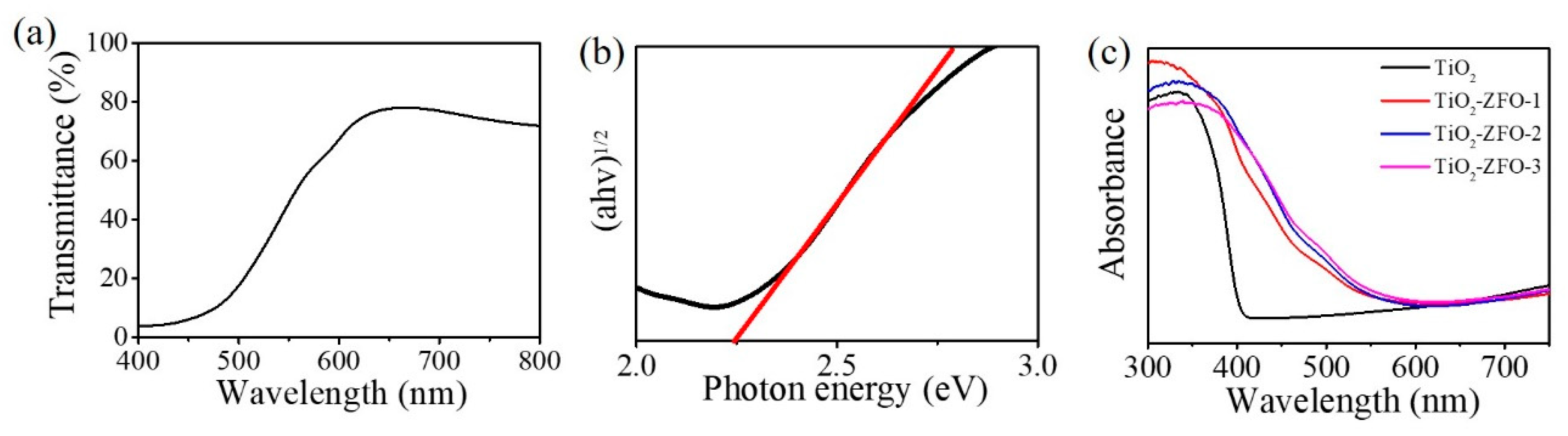
The transmittance spectrum of the ZFO thin film is displayed in
Figure 6a. The film had a strong absorbance edge in the wavelength of 500~650 nm.
Figure 6b shows the estimation of the optical bandgap value of the ZFO thin film by Tauc plot. The optical bandgap value of the ZFO film was 2.25 eV. Furthermore, the UV-Vis diffuse reflectance spectra of the TiO
2 and various TiO
2–ZFO composite nanorods are shown in
Figure 6c. The absorption edge of TiO
2 nanorods were located at approximately 410 nm. TiO
2 nanorods exhibited a strong absorption in the UV range; the estimated bandgap value of the TiO
2 nanorods was approximately 3.02 eV in this work. After the decoration of the ZFO onto the surfaces of the TiO
2 nanorods, the absorption edge of the nanorods was substantially red-shifted to the visible light regions, revealing the improved light harvesting ability of the TiO
2 nanorods via a composite structure. All the TiO
2–ZFO nanorods with various thicknesses of ZFO shell layer presented an intensive absorption from the UV to the visible light region. Comparatively, the optical absorption edge of the TiO
2–ZFO-2 and TiO
2–ZFO-3 nanorods exhibited a larger degree of light harvesting than did the TiO
2–ZFO-1 nanorods. This might be associated with the ZFO crystallite layer thickness effect. The optical absorption edge analysis revealed that the TiO
2–ZFO composite nanorods could absorb more photons than that of the TiO
2 nanorods under solar light irradiation and these composite nanorods are beneficial for photodegrading organic dyes applications.
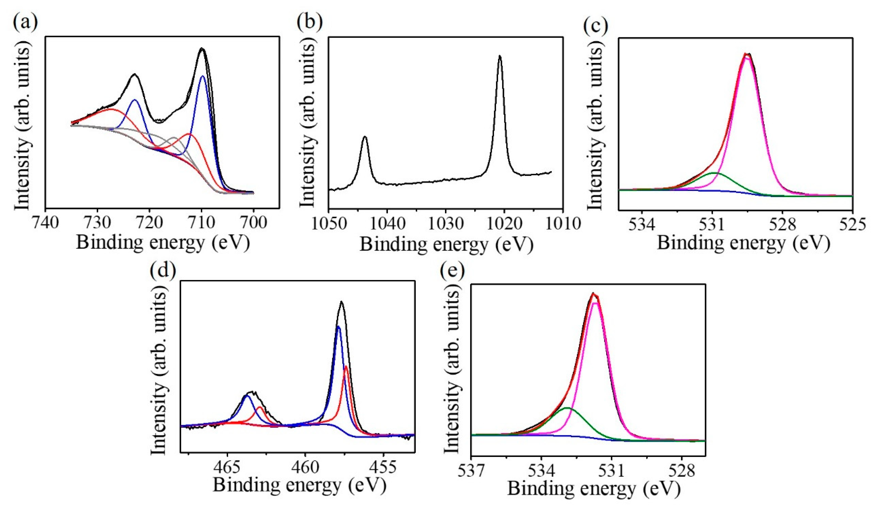
Figure 7a presents the Fe 2p XPS spectrum of the as-deposited ZFO ultra-thin film; the spectrum can be deconvoluted into six subpeaks. The subpeaks situated at 709.7 and 723.1 eV are ascribed to originate from the oxidation state of Fe
2+. The subpeaks located at 711.7 and 726.1 eV are attributed to Fe
3+. The subpeaks situated at 714.8 and 719.1 eV are contributions from the Fe
2+ and Fe
3+ satellite signals, respectively [
12]. The intense peaks of the binding contribution of 711.7 and 726.1 eV demonstrated that Fe in the ZFO crystallites is mainly in a trivalent state. However, the iron binding energy analysis of the ZFO revealed the existence of a small quantity of Fe
+2 in the crystal surface. The Zn 2p XPS spectrum is shown in
Figure 7b. The peaks located respectively at 1044.1 and 1021.1 eV are from Zn 2p
1/2 and Zn 2p
3/2; these binding energies of the Zn 2p imply the existence of Zn
2+ in the ZFO film [
13]. The O 1s XPS spectrum of the ZFO film is shown in
Figure 7c. The fitted subpeaks situated at 530.8 eV are associated with the existence of oxygen vacancies in the oxide film. The peak situated at 529.5 eV corresponded to lattice oxygen bonds in the ZFO film. The XPS result demonstrated that the Zn/Fe atomic ratio is 0.49 which is similar to the stoichiometric Zn/Fe composition ratio of the ZFO. However, the oxygen content slightly deviated from the stoichiometry and is approximately 3.5. The existence of oxygen vacancies in the ZFO crystal might account for the observed mixed iron valence states from the Fe 2p signal.
Figure 7d displays the Ti 2p XPS spectrum of the TiO
2 nanorods. The peak was deconvoluted into four subpeaks, which are located at the binding energy regions of approximately 458.1 eV, corresponding to Ti
4+2p
3/2, at 463.3 eV, corresponding to Ti
4+2p
1/2, at 457.1 eV, corresponding to Ti
3+ 2p
3/2, and at 462.8 eV, corresponding to Ti
3+2p
1/2. The existence of the Ti
4+ and Ti
3+ in the nanorods revealed the presence of oxygen vacancies in the TiO
2 nanorods. The O1s spectrum of the TiO
2 nanorods is shown in
Figure 7e. The deconvoluted subpeak with a relatively high intensity located at approximately 531.2 eV is ascribed to lattice oxygen of TiO
2; that with a relatively lower intensity located at approximately 532.3 originated from the oxygen-deficient defects in the TiO
2. The asymmetric O1s XPS spectrum in
Figure 7e, indicates that oxygen vacancies are present on the TiO
2 surface and this supports the observation of the mixed titanium valence states in the TiO
2 [
14].
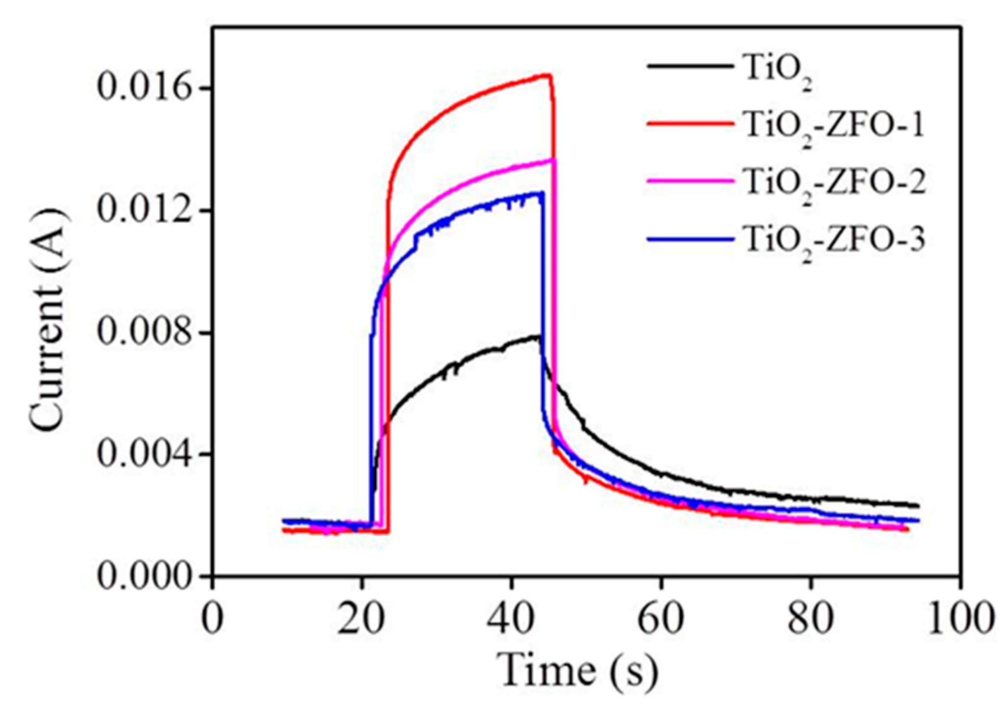
Figure 8 shows the current vs. time curves of the TiO
2 and various TiO
2–ZFO nanorods with and without irradiation. Comparatively, the measured current value is low for all the nanorods at 5V under dark conditions. The dark current of the various nanorods is in the range of 9 × 10
−4~1.41 × 10
−3A. The photocurrent of the nanorods is generated upon light illumination. The photocurrent of the TiO
2 nanorods is approximately 7.9 × 10
−3A under irradiation. Moreover, a larger increment of the current value was observed for the composite nanorods under irradiation. The photocurrent values reached 1.32 × 10
−2A and 1.2 × 10
−2 for the TiO
2–ZFO-2 and TiO
2–ZFO-3 nanorods, respectively. Moreover, the highest photocurrent value of approximately 1.72 × 10
−2A was observed for the TiO
2–ZFO-1 nanorods. A substantial increase of the photocurrent of the TiO
2 coated with the ZFO shell layer was visible. Photo-responses (the ratio of photocurrent to dark current) were 16.8, 13.4, and 12.1, for the TiO
2–ZFO-1, TiO
2–ZFO-2, and TiO
2–ZFO-3 nanorods, respectively. The photo-response of the TiO
2 nanorods was only 6.4 in this study. The TiO
2–ZFO-1 nanorods showed a marked increment of photo-response to approximately 2.5 times higher than that of the TiO
2 nanorods. The photoexcited charges can be responsible for the photocurrent. The intensity of photocurrent is widely used to evaluate the degree of photoexcited charge separation. The rise of the photocurrent means a decreased size of photoexcited charge recombination [
15]. The ZFO is a narrow bandgap oxide, which greatly improved the light harvesting ability of the TiO
2 nanorods. Moreover, the suitable band alignment between the TiO
2 and ZFO caused the photoexcited electrons in the ZFO to be able to transfer to the conduction band of TiO
2; moreover, these free electrons flowed through the TiO
2 nanorods under the bias. [
16,
17]. Similar to heterogeneous WS
2–TiO
2 light detectors, the improved photo-response activity is associated with the type II band structure between the WS
2 and TiO
2 [
5]. Moreover, the TiO
2–SnO
2 nano-heterostructure offers a high charge separation efficiency and a direct pathway for electron transport; therefore, the heterogeneous TiO
2 detector displays a higher photo-response value than that of TiO
2 [
18]. These examples supported the enhanced photo-response of the TiO
2–ZFO nanorods than that in the TiO
2 nanorods herein. An optimal ZFO crystallite size for efficiently improving the photoexcited charge separation in the TiO
2–ZFO heterostructure was observed for the TiO
2–ZFO-1 nanorods in this study.
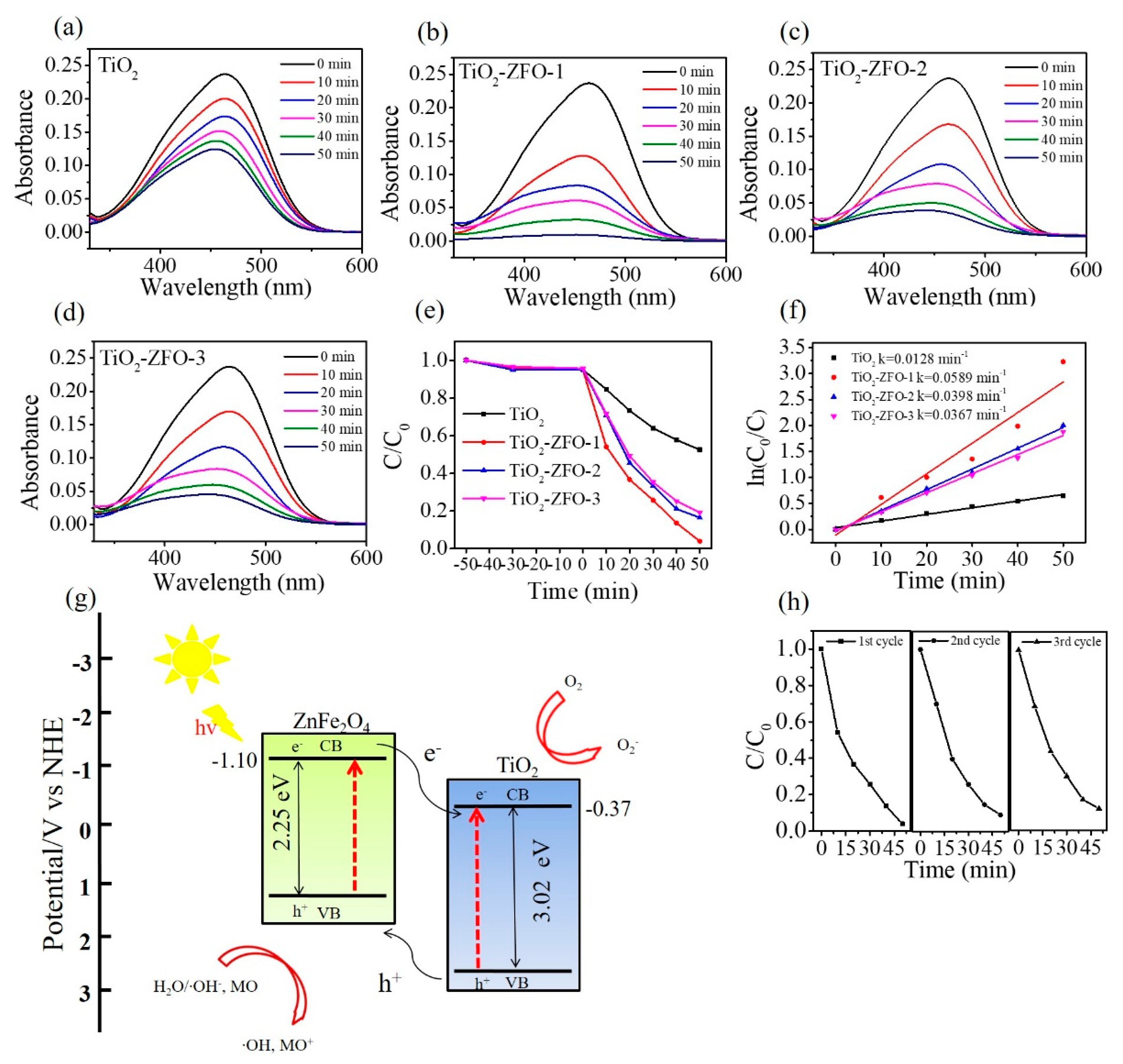
Figure 9a–d shows the intensity change of absorbance spectra of the MO solution containing various nanorod samples with different irradiation durations. The distinct feature at 464 nm is associated with the monomeric MO. The intensity of the absorbance peaks of the MO solution containing various nanorod samples decreased with the irradiation duration, revealing the photocatalytic reaction between the nanorods and the MO solution under irradiation. A series of contrast experiments were carried out and the photodegradation ratios (C/C
o) of the MO solution containing various nanorod samples are summarized in
Figure 9e. In this study, the C
o is the initial concentration of the MO solution without irradiation and C is the concentration of the MO solution with various irradiation times. Notably, prior to illumination, the MO solution containing various nanorod samples was magnetically stirred in the dark for 50 min. Moreover, the peak intensity of the absorbance spectra of the MO solution decreased approximately 6% because partial dye molecules might have been adsorbed onto the surfaces of the nanorods for various nanorod samples under the given dark conditions. From
Figure 9e, approximately 47.5% MO solution was degraded under irradiation for 50 min using TiO
2 nanorods as a photocatalyst. The photodegradation degrees of the MO solution were evaluated to approximately 80.6% and 82.3% when using TiO
2–ZFO-3 and TiO
2–ZFO-2 nanorods as photocatalysts, respectively. Furthermore, the highest photodegradation degree of the MO solution was observed for the MO solution containing the TiO
2–ZFO-1 nanorods at the given degradation reaction condition. For comparison, the kinetic model for photodegrading the MO solution is discussed and the apparent first-order rate constant k was used to evaluating the photodegradation efficiency of different nanorod photocatalysts [
2,
19].
Figure 9f reveals that the plot of ln(C
o/C) vs. irradiation duration (t) is approximating linear. The apparent first-order rate constant k was calculated to be 0.0128, 0.0589, 0.0398, and 0.0367 min
−1 for TiO
2, TiO
2–ZFO-1, TiO
2–ZFO-2, and TiO
2–ZFO-3 nanorods, respectively. When composite nanorods were used as photocatalysts, the photodegradation efficiency of the MO solution accelerated a lot compared with the pure TiO
2 nanorods. Moreover, after coating the appropriate size of the ZFO shell layer, the photodegradation rate of the MO solution was further improved. The photodegradation test results illustrated that the photodegradation ability of the TiO
2 nanorods were substantially improved by decorating ZFO onto the surfaces of the TiO
2 nanorods. This is attributable to the enhanced light harvesting ability of the TiO
2 nanorods coated with the visible light sensitizer of ZFO. Moreover, the photo-response result demonstrated that the photocurrent of the TiO
2 nanorods was substantially enhanced through the surface coating of ZFO. The formation of type II band structure between the TiO
2 and ZFO is important for the improved photodegradation ability. The effective photogenerated charge separation at the heterointerfaces significantly improved the photodegradation performance of composite nanorods toward organic dyes. This is supported by the case that the construction of ZnO–ZnS core-shell nanorods because of suitable type II band alignment at the heterointerface, substantially improves photodegradation efficiency toward methylene blue dyes [
20]. Similarity, the ZnO–SnO
2 and ZnO–Zn
2SnO
4 core-shell nanorods also have a type II band alignment between the constituent compounds and they demonstrate superior photodegradation ability than that of ZnO toward rhodamine B dyes [
13].
Figure 9g illustrates the band alignment structure between the TiO
2 and ZFO and the photodegradation mechanism of the TiO
2–ZFO composite nanorods. The conduction band (CB) and valence band (VB) positions of the TiO
2 are determined at
−0.37 and 2.65 eV (vs. NHE), respectively [
16]. The CB and VB of ZFO are at
−1.10 and 1.15 eV (vs. NHE), respectively [
17]. Under irradiation, the photogenerated holes in TiO
2 will migrate to the ZFO. Moreover, the photogenerated electrons in ZFO could migrate to the TiO
2. This process could improve the photogenerated charge separation efficiency and decline greatly the rate of charge recombination. Therefore, the formation of TiO
2–ZFO heterojunction structure led to the improvement of photodegradation efficiency of the composite nanorods. The possible photodegradation reactions of the TiO
2–ZFO composite nanorods with the MO dyes under irradiation are described as follows:
For a series of TiO
2–ZFO nanorod samples, the TiO
2–ZFO-1 exhibited superior photodegradation ability toward MO dyes among the various composite nanorods. This might be associated with the fact that thicker ZFO crystallite sizes on the TiO
2 nanorods engendered the decreased separation efficiency of photogenerated charges in the composites, therefore leading to a decrease of photodegradation rate of the composite nanorods toward MO dyes. This is supported by the observation of different photocurrent values among the various TiO
2–ZFO nanorods. The increased ZFO shell crystallite size in the TiO
2–ZFO composite nanorods although is advantageous to generate a greater number of electron-hole pairs in the ZFO side under the given irradiation; however, an increased travel path for the charges to across the heterointerface from ZFO to TiO
2 might increase the possibility of recombination of charges. Therefore, the TiO
2–ZFO-1 nanorods exhibited an optimal ZFO shell size and the highest photodegradation performance among various TiO
2–ZFO nanorods herein. To further test the stability of the TiO
2–ZFO-1 photocatalysts, recycling tests were conducted. As shown in
Figure 9h, the photodegradation rate of the sample remains at a similar level after three consecutive cycles, implying that the obtained TiO
2–ZFO heterogeneous photocatalyst has a high stability during photodegradation of the MO dyes.


