Experimental Investigation on 3D Graphene-CNT Hybrid Foams with Different Interactions


 ,
, 
Abstract
1. Introduction
2. Materials and Methods
2.1. Materials
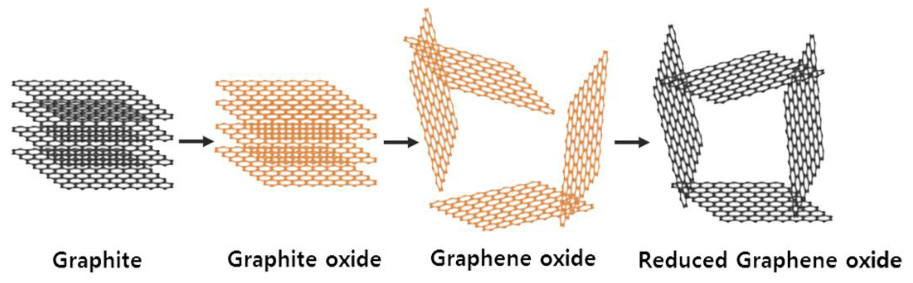
2.2. Synthesis of Graphene Oxide
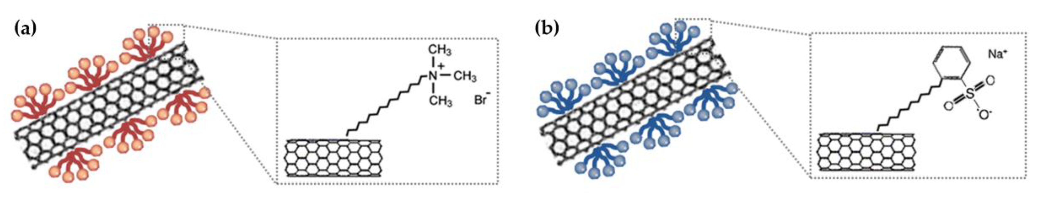
2.3. Preparation of CNT Dispersion
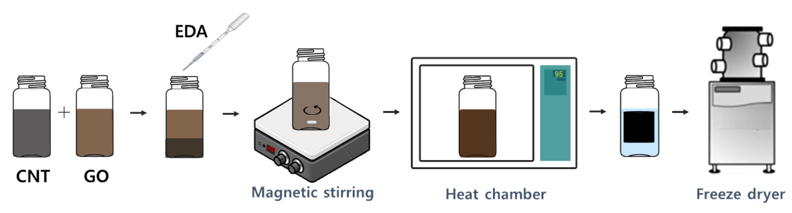
2.4. Fabrication of Graphene-CNT Hybrid Foams
2.5. Characterization
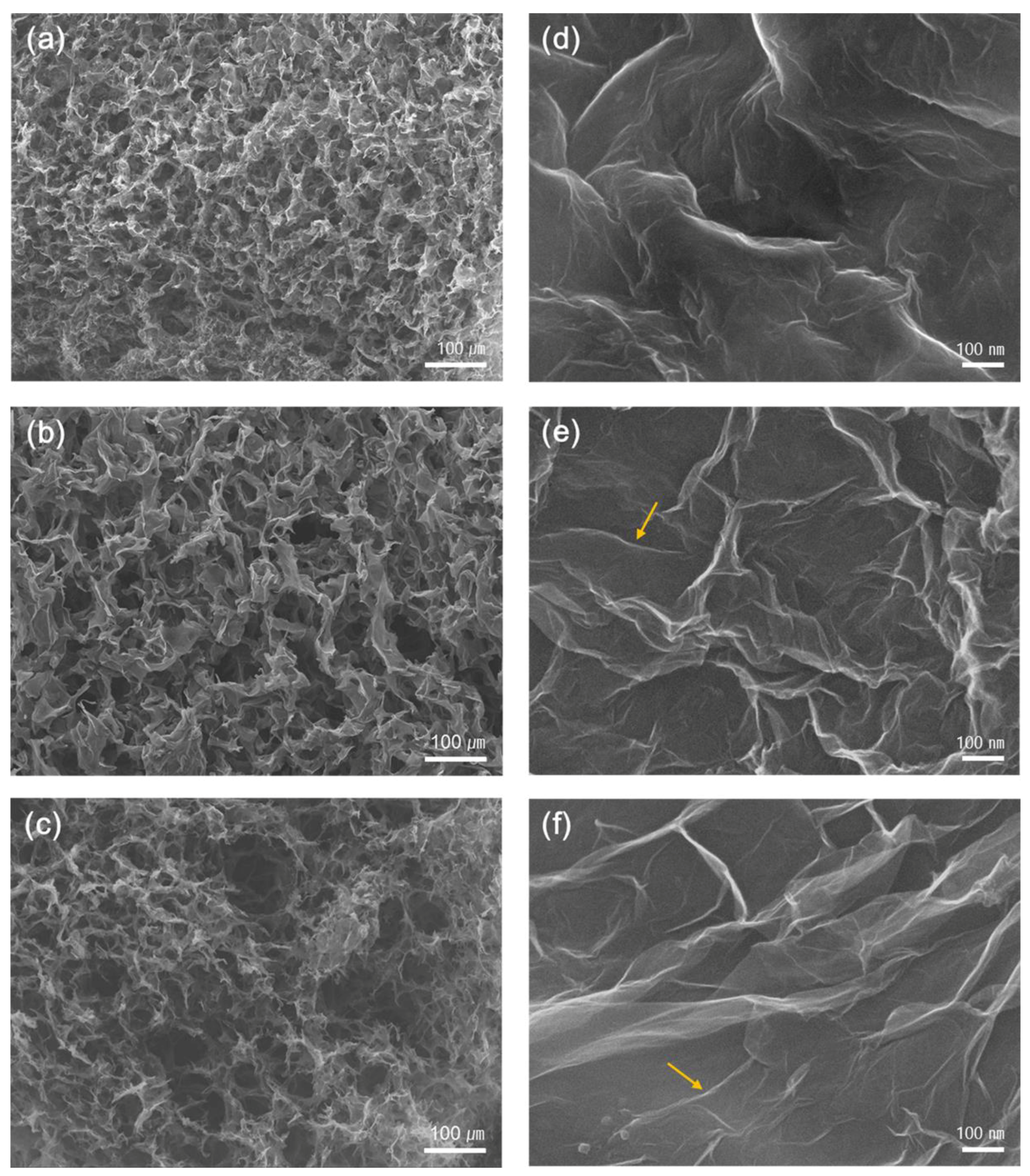
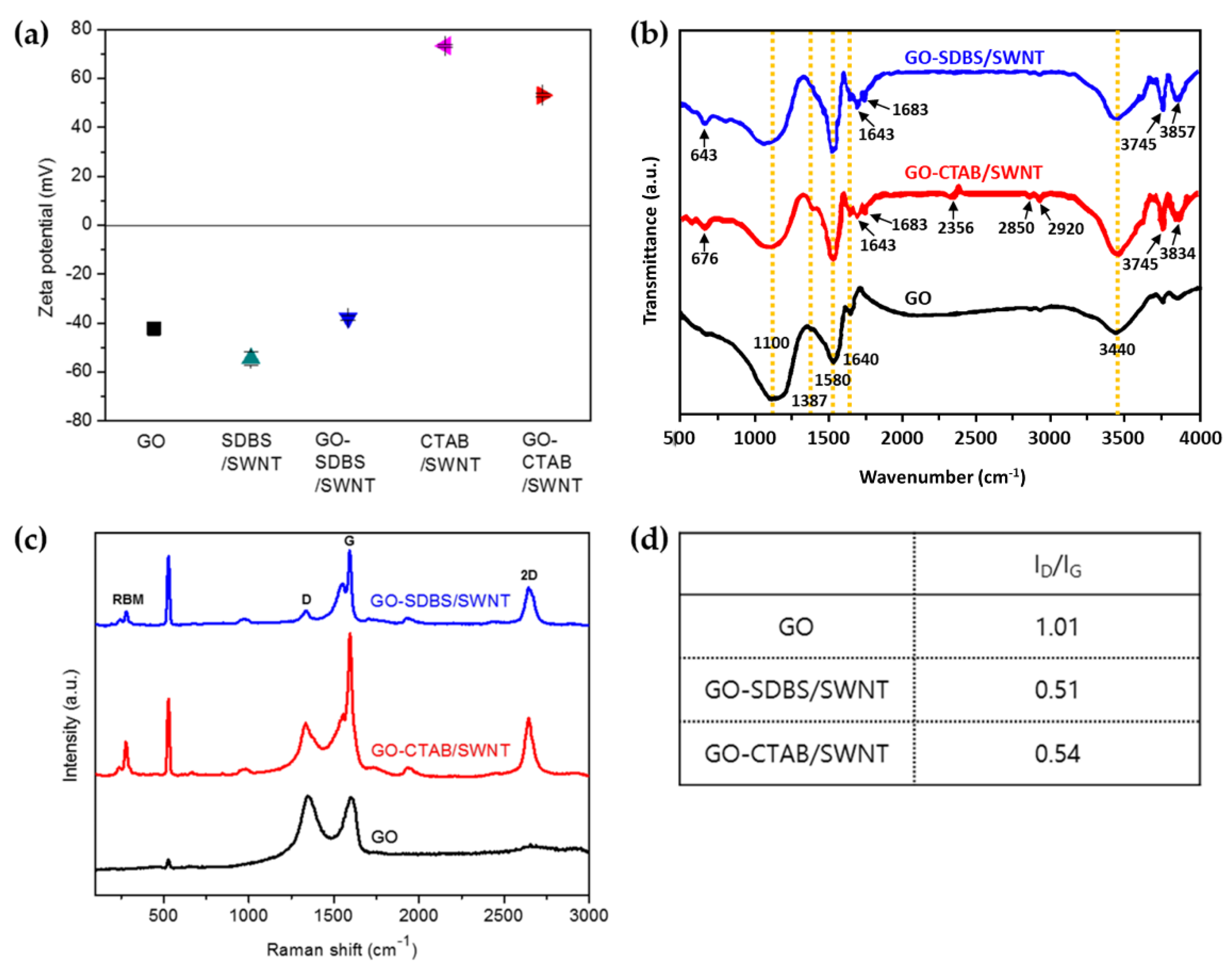
3. Results and Discussion
4. Conclusions
Author Contributions
Funding
Conflicts of Interest
References
- Wang, X.; Xing, W.; Zhang, P.; Song, L.; Yang, H.; Hu, Y. Covalent functionalization of graphene with organosilane and its use as a reinforcement in epoxy composites. Comp. Sci. Technol. 2012, 72, 737–743. [Google Scholar] [CrossRef]
- Worsley, M.A.; Olson, T.Y.; Lee, J.R.; Willey, T.M.; Nielsen, M.H.; Roberts, S.K.; Pauzauskie, P.J.; Biener, J.; Satcher, J.H., Jr.; Baumann, T.F. High surface area, sp2-cross-linked three-dimensional graphene monoliths. J. Phys. Chem. Lett. 2011, 2, 921–925. [Google Scholar] [CrossRef] [PubMed]
- Balandin, A.A.; Ghosh, S.; Bao, W.; Calizo, I.; Teweldebrhan, D.; Miao, F.; Lau, C.N. Superior thermal conductivity of single-layer graphene. Nano Lett. 2008, 8, 902–907. [Google Scholar] [CrossRef] [PubMed]
- Stoller, M.D.; Park, S.; Zhu, Y.; An, J.; Ruoff, R.S. Graphene-based ultracapacitors. Nano Lett. 2008, 8, 3498–3502. [Google Scholar] [CrossRef] [PubMed]
- Zhu, Y.; Murali, S.; Cai, W.; Li, X.; Suk, J.W.; Potts, J.R.; Ruoff, R.S. Graphene and graphene oxide: Synthesis, properties, and applications. Adv. Mater. 2010, 22, 3906–3924. [Google Scholar] [CrossRef] [PubMed]
- Novoselov, K.S.; Fal, V.; Colombo, L.; Gellert, P.; Schwab, M.; Kim, K. A roadmap for graphene. Nature 2012, 490, 192. [Google Scholar] [CrossRef] [PubMed]
- Chua, C.K.; Pumera, M. Chemical reduction of graphene oxide: A synthetic chemistry viewpoint. Chem. Soc. Rev. 2014, 43, 291–312. [Google Scholar] [CrossRef] [PubMed]
- Avouris, P.; Dimitrakopoulos, C. Graphene: Synthesis and applications. Mater. Today 2012, 15, 86–97. [Google Scholar] [CrossRef]
- Nardecchia, S.; Carriazo, D.; Ferrer, M.L.; Gutiérrez, M.C.; del Monte, F. Three dimensional macroporous architectures and aerogels built of carbon nanotubes and/or graphene: Synthesis and applications. Chem. Soc. Rev. 2013, 42, 794–830. [Google Scholar] [CrossRef] [PubMed]
- Hu, H.; Zhao, Z.; Wan, W.; Gogotsi, Y.; Qiu, J. Ultralight and highly compressible graphene aerogels. Adv. Mater. 2013, 25, 2219–2223. [Google Scholar] [CrossRef] [PubMed]
- Zhang, L.; Chen, G.; Hedhili, M.N.; Zhang, H.; Wang, P. Three-dimensional assemblies of graphene prepared by a novel chemical reduction-induced self-assembly method. Nanoscale 2012, 4, 7038–7045. [Google Scholar] [CrossRef] [PubMed]
- Cao, X.; Shi, Y.; Shi, W.; Lu, G.; Huang, X.; Yan, Q.; Zhang, Q.; Zhang, H. Preparation of novel 3d graphene networks for supercapacitor applications. Small 2011, 7, 3163–3168. [Google Scholar] [CrossRef] [PubMed]
- Chen, Z.; Ren, W.; Gao, L.; Liu, B.; Pei, S.; Cheng, H.-M. Three-dimensional flexible and conductive interconnected graphene networks grown by chemical vapour deposition. Nat. Mater. 2011, 10, 424. [Google Scholar] [CrossRef] [PubMed]
- Yao, H.B.; Ge, J.; Wang, C.F.; Wang, X.; Hu, W.; Zheng, Z.J.; Ni, Y.; Yu, S.H. A flexible and highly pressure-sensitive graphene–polyurethane sponge based on fractured microstructure design. Adv. Mater. 2013, 25, 6692–6698. [Google Scholar] [CrossRef] [PubMed]
- Klionsky, D.J.; Abdalla, F.C.; Abeliovich, H.; Abraham, R.T.; Acevedo-Arozena, A.; Adeli, K.; Agholme, L.; Agnello, M.; Agostinis, P.; Aguirre-Ghiso, J.A. Guidelines for the use and interpretation of assays for monitoring autophagy. Autophagy 2012, 8, 445–544. [Google Scholar] [CrossRef] [PubMed]
- Yu, M.-F.; Files, B.S.; Arepalli, S.; Ruoff, R.S. Tensile loading of ropes of single wall carbon nanotubes and their mechanical properties. Phys. Rev. Lett. 2000, 84, 5552. [Google Scholar] [CrossRef] [PubMed]
- Qian, D.; Wagner, G.J.; Liu, W.K.; Yu, M.-F.; Ruoff, R.S. Mechanics of carbon nanotubes. Appl. Mech. Rev. 2002, 55, 495–533. [Google Scholar] [CrossRef]
- Cao, A.; Dickrell, P.L.; Sawyer, W.G.; Ghasemi-Nejhad, M.N.; Ajayan, P.M. Super-compressible foamlike carbon nanotube films. Science 2005, 310, 1307–1310. [Google Scholar] [CrossRef] [PubMed]
- Peng, B.; Locascio, M.; Zapol, P.; Li, S.; Mielke, S.L.; Schatz, G.C.; Espinosa, H.D. Measurements of near-ultimate strength for multiwalled carbon nanotubes and irradiation-induced crosslinking improvements. Nat. Nanotechnol. 2008, 3, 626. [Google Scholar] [CrossRef] [PubMed]
- Vaisman, L.; Wagner, H.D.; Marom, G. The role of surfactants in dispersion of carbon nanotubes. Adv. Coll. Interface Sci. 2006, 128, 37–46. [Google Scholar] [CrossRef] [PubMed]
- Hummers, W.S., Jr.; Offeman, R.E. Preparation of graphitic oxide. J. Am. Chem. Soc. 1958, 80, 1339. [Google Scholar] [CrossRef]
- Wang, L.; Kang, J.; Nam, J.-D.; Suhr, J.; Prasad, A.K.; Advani, S.G. Composite membrane based on graphene oxide sheets and nafion for polymer electrolyte membrane fuel cells. ECS Electrochem. Lett. 2015, 4, F1–F4. [Google Scholar] [CrossRef]
- Chen, W.; Yan, L. In situ self-assembly of mild chemical reduction graphene for three-dimensional architectures. Nanoscale 2011, 3, 3132–3137. [Google Scholar] [CrossRef] [PubMed]
- Ma, Z.; Zhao, X.; Gong, C.; Zhang, J.; Zhang, J.; Gu, X.; Tong, L.; Zhou, J.; Zhang, Z. Preparation of a graphene-based composite aerogel and the effects of carbon nanotubes on preserving the porous structure of the aerogel and improving its capacitor performance. J. Mater. Chem. A 2015, 3, 13445–13452. [Google Scholar] [CrossRef]
- Hunter, R.J. Zeta Potential in Colloid Science: Principles and Applications; Academic Press: Cambridge, MA, USA, 2013; Volume 2. [Google Scholar]
- Veerapandian, M.; Zhang, L.; Krishnamoorthy, K.; Yun, K. Surface activation of graphene oxide nanosheets by ultraviolet irradiation for highly efficient anti-bacterials. Nanotechnology 2013, 24, 395706. [Google Scholar] [CrossRef] [PubMed]
- Hussain, S.; Jha, P.; Chouksey, A.; Raman, R.; Islam, S.; Islam, T.; Choudhary, P. Spectroscopic investigation of modified single wall carbon nanotube (swcnt). J. Mod. Phys. 2011, 2, 538–543. [Google Scholar] [CrossRef]
- Mohiuddin, T.; Lombardo, A.; Nair, R.; Bonetti, A.; Savini, G.; Jalil, R.; Bonini, N.; Basko, D.; Galiotis, C.; Marzari, N. Uniaxial strain in graphene by raman spectroscopy: G peak splitting, grüneisen parameters, and sample orientation. Phys. Rev. B 2009, 79, 205433. [Google Scholar] [CrossRef]
- Jorio, A. Raman spectroscopy in graphene-based systems: Prototypes for nanoscience and nanometrology. ISRN Nanotechnol. 2012, 2012. [Google Scholar] [CrossRef]


| Property | GO | GO-SDBS/SWNT | GO-CTAB/SWNT | % Increased |
|---|---|---|---|---|
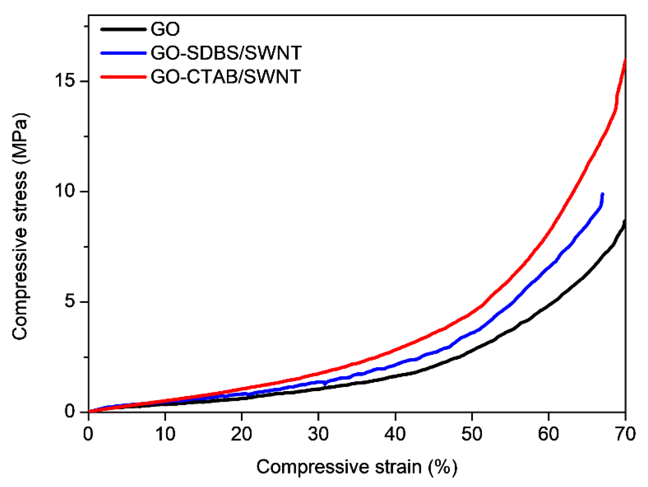
| E (MPa) | 35 | 65 | 90 | (157% increase) |
| Strength at 10% strain (MPa) | 0.35 | 0.52 | 0.54 | (54.3% increase) |
© 2018 by the authors. Licensee MDPI, Basel, Switzerland. This article is an open access article distributed under the terms and conditions of the Creative Commons Attribution (CC BY) license (http://creativecommons.org/licenses/by/4.0/).
Share and Cite
Kim, H.-s.; Lee, S.K.; Wang, M.; Kang, J.; Sun, Y.; Jung, J.W.; Kim, K.; Kim, S.-M.; Nam, J.-D.; Suhr, J. Experimental Investigation on 3D Graphene-CNT Hybrid Foams with Different Interactions. Nanomaterials 2018, 8, 694. https://doi.org/10.3390/nano8090694
Kim H-s, Lee SK, Wang M, Kang J, Sun Y, Jung JW, Kim K, Kim S-M, Nam J-D, Suhr J. Experimental Investigation on 3D Graphene-CNT Hybrid Foams with Different Interactions. Nanomaterials. 2018; 8(9):694. https://doi.org/10.3390/nano8090694
Chicago/Turabian StyleKim, Hye-soo, Stephanie K. Lee, Mei Wang, Junmo Kang, Yan Sun, Jae Wook Jung, Kyunghoon Kim, Sung-Min Kim, Jae-Do Nam, and Jonghwan Suhr. 2018. "Experimental Investigation on 3D Graphene-CNT Hybrid Foams with Different Interactions" Nanomaterials 8, no. 9: 694. https://doi.org/10.3390/nano8090694
APA StyleKim, H.-s., Lee, S. K., Wang, M., Kang, J., Sun, Y., Jung, J. W., Kim, K., Kim, S.-M., Nam, J.-D., & Suhr, J. (2018). Experimental Investigation on 3D Graphene-CNT Hybrid Foams with Different Interactions. Nanomaterials, 8(9), 694. https://doi.org/10.3390/nano8090694