3.1. Fabrication and Characterization of CNT FG FET Ion Sensors
One of the main challenges with silicon-based ion-sensitive field-effect transistors (ISFETs) is the corrosion of silicon and silicon oxide under high ionic strength. This corrosion alters the threshold voltage of the FET, leading to performance degradation over time [
18]. In contrast, CNTs offer exceptional chemical and physical stability in physiological solutions due to their unique properties and structure. However, direct exposure of CNT channels to the environment can result in irreversible ion adsorption. This can cause local charge accumulation, negatively affecting the sensing performance and long-term stability of the device. To address this issue, we introduce a high-κ gate dielectric layer in our floating-gate structure with a hafnium oxide layer to enhance the ionic stability of the device.
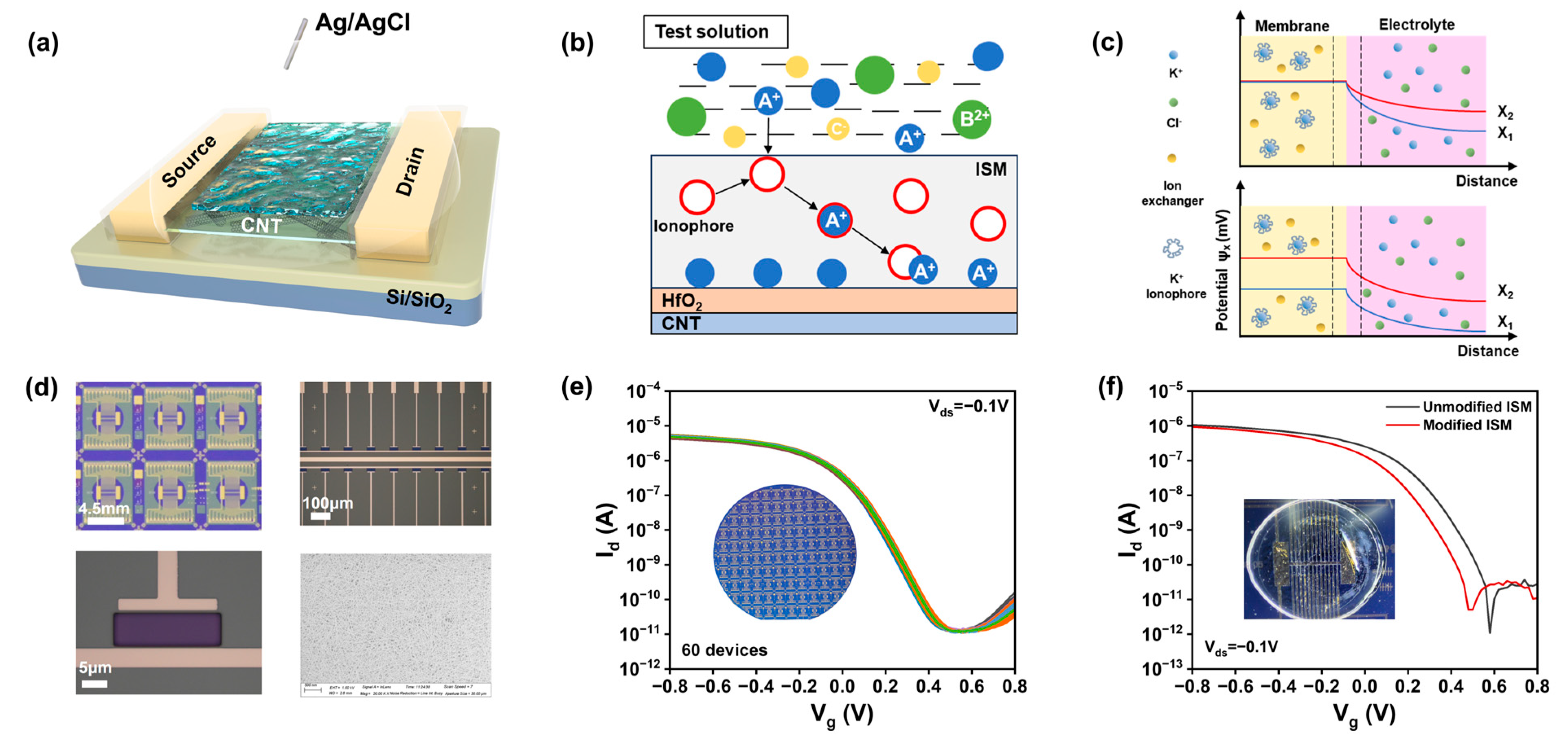
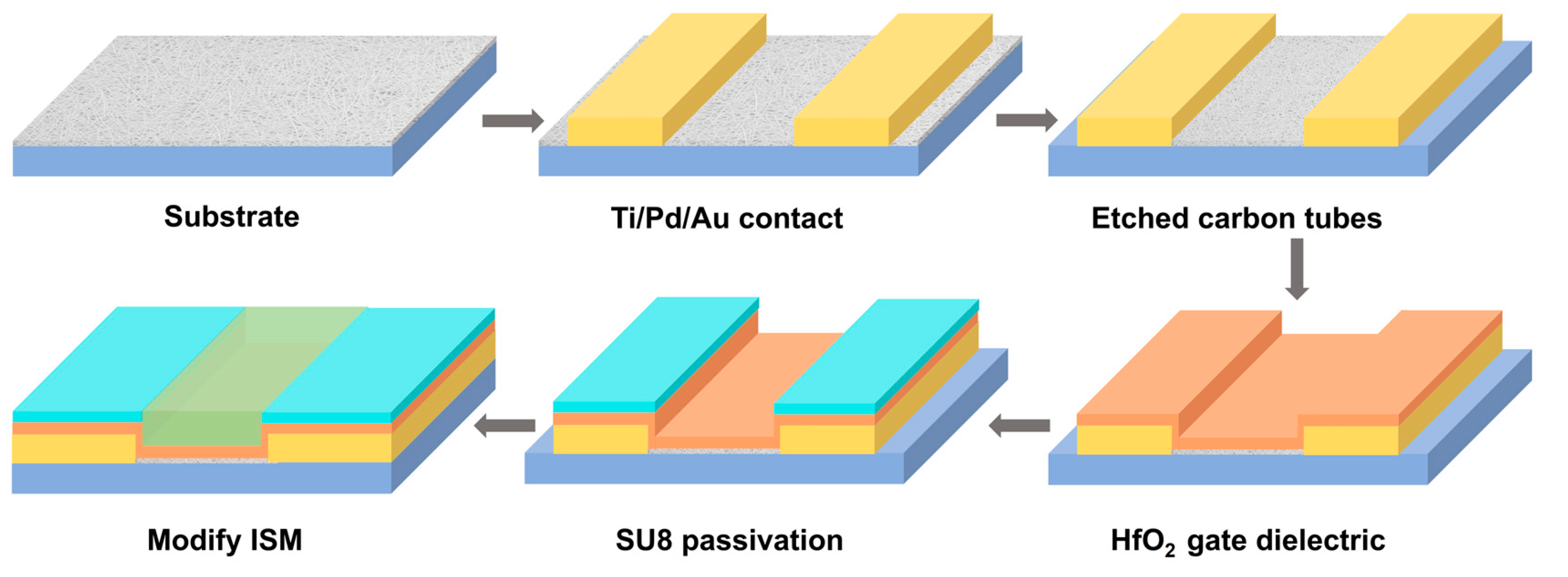
Figure 1a illustrates a schematic of the ISM-functionalized CNT FG FET ion sensor. The carbon-based sensing chip utilized in this study was fabricated on a 4-inch, 200 μm thick silicon wafer with carbon nanotubes. The CNT FG FET ion sensor was manufactured through a process depicted in
Figure A1, which is analogous to previously reported methods, with all fabrication steps based on photolithography techniques. Each sensing unit consists of a 20 × 40 μm carbon nanotube channel and two Ti (0.3 nm)/Pd (40 nm)/Au (30 nm) source/drain electrodes. The CNT FG FET sensors were constructed in an array to enhance the reliability of sensor measurements. The optical image of the fabricated carbon-based field-effect transistor sensor is shown in
Figure 1d, with each sensor chip incorporating 22 FET sensors.
To achieve reliable ion detection, the sensor must exhibit good uniformity and repeatability. We assessed the electrical performance of the fabricated ISFETs by measuring the transfer curves of 60 CNT FG FET devices at a source-drain voltage of −0.1 V in 100 mM Tris-HCl buffer solution (
Figure 1e). The results indicate that the FETs possess highly uniform transfer characteristics, and the current variation coefficient of the device is within 7%. All transistors exhibit p-type FET behavior, with a highly uniform threshold, voltage transconductance, and subthreshold swing (
Figure A3). The transfer characteristics curves reveal an excellent ion current on–off ratio (I
on/I
OFF) of 10
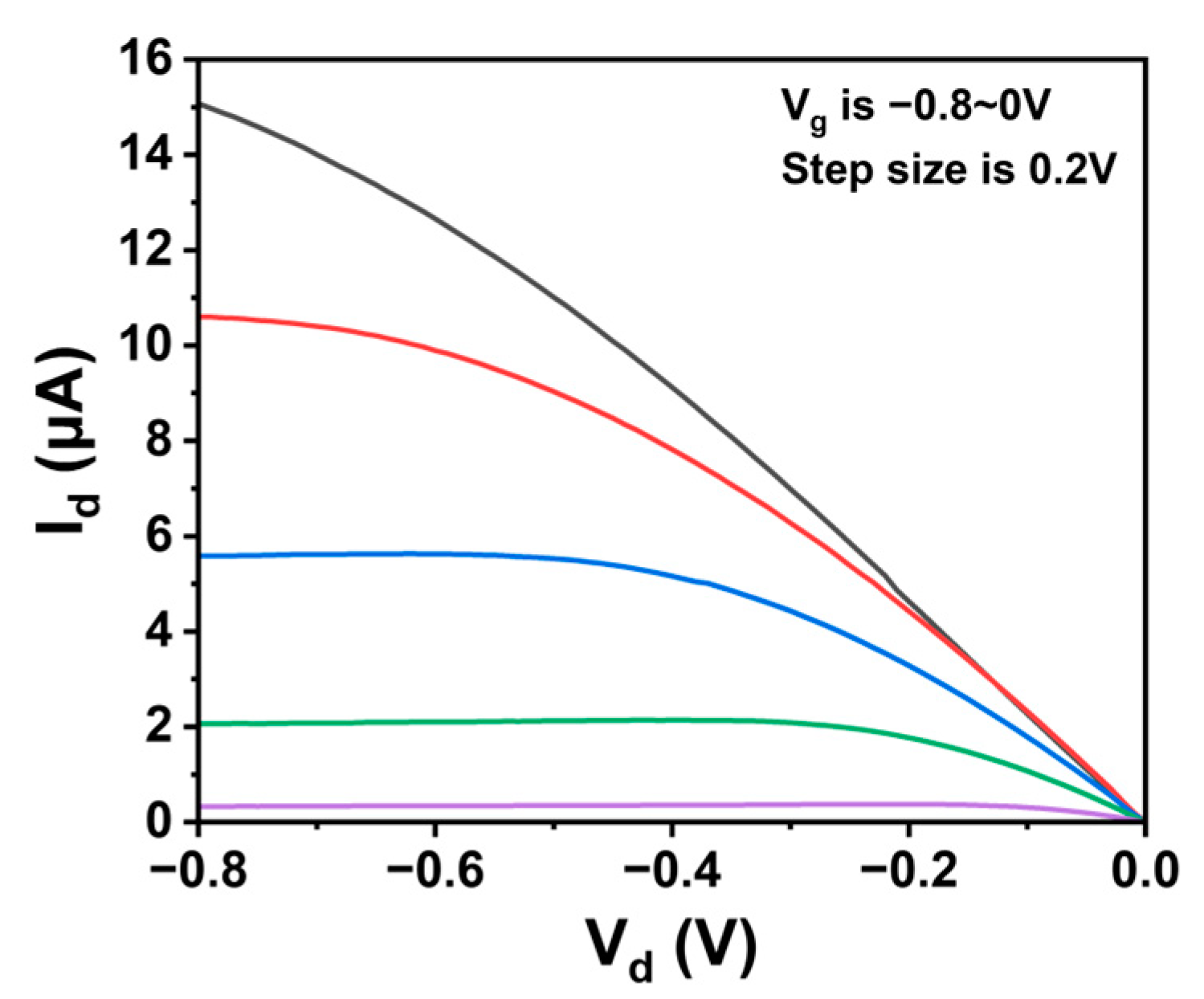
6 and subthreshold swing (SS) of 87 mV/dec. The linear output curves at low biases (
Figure A4) are attributed to ohmic contacts, which minimize contact resistance, mitigate the impact of channel resistance on the total device resistance, and ultimately maximize sensor response. Notably, the absence of hysteresis and the SS of 87 mV/dec suggest that, due to charge variations on the CNT FET, the CNT FET can provide stable and substantial changes in on-state current, which is crucial for the desired reliable detection. The gate leakage is maintained within 10 pA, which is negligible compared to the drain current over the entire range of gate bias operation.
3.2. Effect of Gate Dielectric on Ion Detection Performance
In comparing the effects of the presence and absence of a gate dielectric on ion detection, we conducted multiple tests and obtained the transfer characteristic curve of the device as shown in
Figure 2a,b. The direction of the arrow represents the increase in the number of tests. It was observed that the on-state current of the transfer characteristic curve of the device without a gate dielectric decreased significantly with multiple tests as shown in
Figure 2a. The on-state current of the transfer characteristic curve of the device with a gate dielectric remained basically unchanged as shown in
Figure 2b. Extracting the transconductance of the device from the transfer curve in
Figure 2c, it can be seen that the transconductance of the device without a gate dielectric is constantly decreasing, while the transconductance of the device with a gate dielectric changes less, indicating that the stability of the device with a gate dielectric is better. This is because when there is no gate dielectric in the channel, a part of the ions enter the channel through the selective membrane, resulting in local charge accumulation and reduced stability of the device, as shown in
Figure 2d [
19]. When a gate dielectric is present, the gate dielectric layer prevents ions from entering the channel, thereby protecting the channel area from the influence of the solution environment and improving the long-term stability of the device. Therefore, even after multiple tests, the device with a gate dielectric still maintains good performance.
Due to its high dielectric constant, hafnium oxide (HfO
2) can provide greater gate control, thereby enhancing the sensitivity and switching characteristics of the device [
20]. Hafnium oxide exhibits excellent resistance in various environments, which helps to improve the long-term stability and reliability of the device. Moreover, HfO
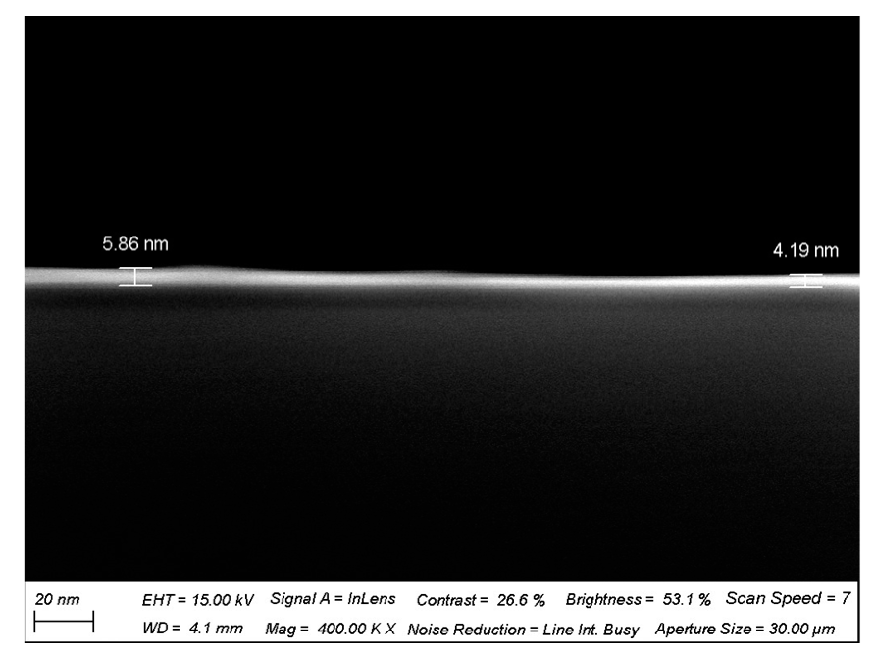
2 is highly compatible with CNTs, facilitating the maintenance of CNT electronic properties and enabling integration with CNT FETs. To improve the stability of the ion sensor and maintain excellent detection performance in complex background environments, a 5 nm thick hafnium oxide high-k gate dielectric was deposited as a floating-gate insulating layer over the entire CNT channel, isolating the channel from the solution and enhancing the transistor’s gate control capability [
21].
Figure A2 is an SEM cross-sectional view of the deposited HfO
2 gate dielectric, which has a thickness of about 5 nm. A 500 nm SU8 passivation layer was spin-coated on top of the device to protect the electrodes and pads from the influence of the solution environment and to prevent device leakage, with patterning performed to leave openings in the sensing area above the carbon nanotube channel.
3.3. Detection Principle of CNT FG FET Ion Sensors
ISMs are polymeric membranes containing ionophore groups that possess the capability to selectively permeate ions within a solution [
22]. By coating the surface of an ISFET with an ISM containing ionophores, the ISFET is endowed with selectivity towards the target ion.
Figure 1b illustrates the process by which the ionophores within the ISM on the surface of the ion sensor bind with target ions in the solution; only ions that match the pore size and charge characteristics can pass through the membrane, while others are blocked. The interaction between the ionophores for K
+, Na
+, and Ca
2+ and their corresponding target ions follows this mechanism [
23], and the details of the ISM coating preparation are discussed in the experimental section. The performance of the ion sensor before and after the modification with the selective membrane was tested, and it was found that the carrier mobility of the CNT FET did not significantly change during the deposition of the ion membrane in
Figure 1f. This indicates that the ion membrane performs a non-covalent functionalization of the carbon nanotubes, imparting ion sensitivity while maintaining carrier mobility.
The mechanism of pH sensing involves the reversible binding of hydrogen ions to the active hydroxyl groups on the surface of HfO
2, as depicted in
Figure A5. In acidic solutions, the hydroxyl groups (–OH) become protonated to form hydronium ions (–OH
2+), leading to the accumulation of positive charges on the surface of HfO
2. This causes the energy bands to bend further downwards, creating a higher hole barrier and ultimately reducing the on-state current (I
on). Conversely, in an alkaline environment, the hydroxyl groups become deprotonated to form negatively charged oxygen atoms (–O
−), resulting in the accumulation of negative charges on the surface of HfO
2. This forms a lower hole Schottky barrier, thereby increasing the on-state current [
24].
When the functionalized device comes into contact with an electrolyte solution, the ionophore within the ISM selectively captures the target ions in the solution, causing a change in the gate potential as shown in
Figure 1c [
25]. X
1 is the initial ion concentration of the solution, and X
2 is the ion concentration of the solution after the change. When the target ion concentration in the solution changes from X
1 to X
2, the concentration in the membrane remains in a buffer state and remains at a constant value. A charge separation layer (diffusion layer) with a thickness of several nanometers appears at the interface between the membrane and the solution. The concentration gradient between the solution and the membrane generates a potential difference on the diffusion layer. The potential at the electrolyte–membrane interface increases with the concentration of cations in the solution, necessitating an increased electric field to counteract diffusion, thus causing the potential to rise with increasing ion concentration [
26]. An increase in cation concentration leads to greater p-doping of the channel, resulting in a leftward shift of the I-V characteristic curve. We can detect changes in the drain-source current to obtain information about the concentration of the target ions, which is the working principle of the ion-sensitive field-effect transistor. The relationship between the change in gate potential and ion concentration conforms to the Nernst equation, and the drain-source current is linearly related to the logarithm of ion concentration.
In the equation, 2.303 is the conversion factor from the natural logarithm to the base-10 logarithm, R is the gas constant (8.135 J/(K·mol)), T is the absolute temperature in Kelvin, z is the ion valence, and F is Faraday’s constant (9.684 × 10⁴ C/mol). M0 and Mi represent the ion concentrations outside and inside the membrane, respectively. Therefore, at room temperature, for monovalent ions (z = 1), the Nernst limit is 59 mV/decade. For divalent ions (z = 2), the Nernst limit is 29.5 mV/decade.
By characterizing the sensors with different ISMs, the versatility of the sensing system is demonstrated. When using neutral ionophores, it is necessary to incorporate lipophilic ion sites with the opposite charge of the analyte ion to prevent the extraction of chloride into the membrane. The concentration of these ion sites within the membrane can be optimized to effectively reduce response time, decrease membrane resistance, and enhance selectivity [
27].
3.4. Performance of CNT FG FET Ion Sensors
All electrical tests were conducted using a probe station, with the Keithley 4200 semiconductor analyzer performing transfer curve and real-time tests on the FET sensors. To measure the
Ids-
Vgs curves, the source-drain voltage (
Vds) was set to −0.1 V, and the gate voltage (
Vgs) was scanned from −0.8 V to 0.6 V using an Ag/AgCl reference electrode, while simultaneously measuring the source-drain current (
Ids). The Ag/AgCl reference electrode served as the electrolyte gate electrode to enhance the stability of the tests [
28]. All experiments were carried out at room temperature in an electrolyte solution supported by 100 mM Tris-HCl buffer solution (pH 7.4), and all tests involving the electrical characteristics of the FET devices were performed with a liquid gate. Solutions of different concentrations were prepared using 100 mM Tris-HCl buffer solution to ensure consistent chloride ion concentration across the solutions, minimizing the impact of chloride ion concentration variations on the reference electrode potential and ensuring that the response was due to changes in ion concentration [
29].
This study demonstrated the versatility of the potentiometric sensor device by integrating CNT field-effect transistors with various ISMs, exhibiting high sensitivity and real-time response to the corresponding target ions (K
+, Na
+, Ca
2+, and H
+), as shown in
Figure 3. The relationship between ion concentration and transfer characteristic curves in carbon-based field-effect transistors was investigated by measuring solutions of KCl, NaCl, CaCl
2 within the range of 10 μM to 100 mM, as well as pH solutions from pH 3 to pH 9. When the device channel did not have an ion-selective membrane, the device responded minimally to ions within the concentration range in 100 mM Tris-HCl buffer solution [
30], as seen in
Figure A6, indicating that FET sensors without an ISM cannot distinguish the charge changes in different ions; hence, the bare chip cannot detect ion concentrations.
After testing the response of the background solution and waiting for stabilization, 7 μL of ion solution was pipetted onto the sensor channel; this was followed by electrical measurements. After measuring one concentration, the solution was blotted dry with a lint-free paper before the next concentration was applied.
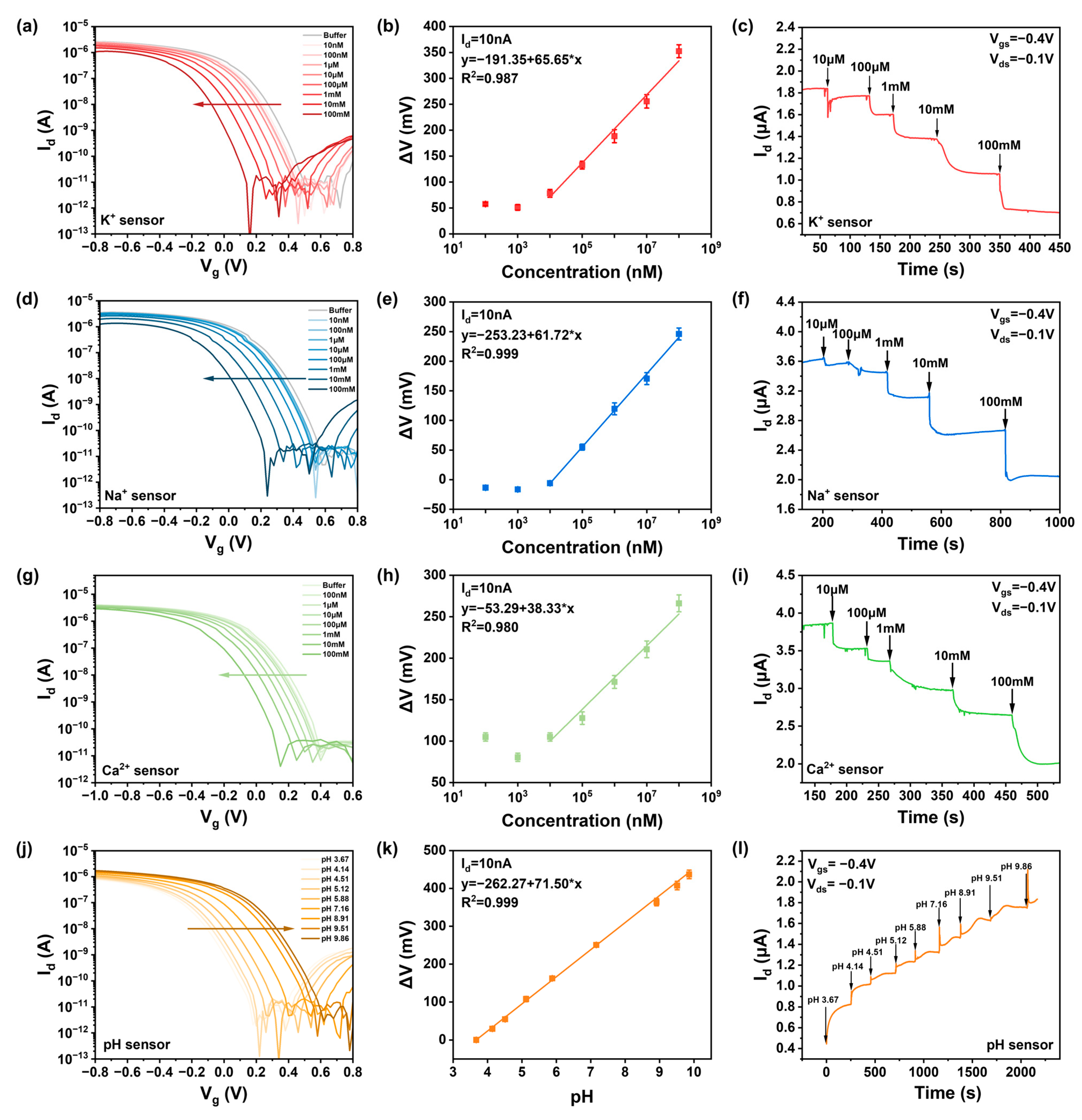
Figure 3 shows the response performance of sensors with ISM-functionalized gate electrodes in ion solutions within the concentration range of 10 μM–100 mM. As shown in
Figure 3a,d,g, the increase in potassium, sodium, and calcium ion concentrations introduced more positive charges at the sensor–electrolyte interface, leading to a decrease in drain current in p-type devices and a regular leftward shift in the transfer curves. This indicates that ions in the solution can be effectively detected within the concentration range of 10 μM–100 mM. The pH sensor, as pH increases and H
+ concentration decreases, shows an increase in drain current, causing the transfer curve to shift to the right as shown in
Figure 3j. The threshold voltage is strongly logarithmically dependent on the molar concentration of specific ions. Based on transfer characteristic curve diagrams, the difference (Δ
V) between the
Vi values corresponding to different concentration curves at
Id = 10 nA and the
Vo of the background solution can be taken as a function of ion concentration, as shown in
Figure 3b,e,h,k, yielding sensitivities of K-66 mV/dec, Na-62 mV/dec, Ca-39 mV/dec, and pH-71 mV/dec for the CNT FET ion sensors. The sensitivity of the CNT FET ion sensors approaches the Nernst limit of 59.6 mV/pH, achieving high sensitivity to potassium, sodium, calcium, and hydrogen ions over the concentration range of 10 μM–100 mM and pH 3 to pH 9.
By sequentially adding 2 μL of ion solutions ranging from 10 μM to 100 mM, the real-time current response of the ISM-functionalized CNT FET ion sensors was investigated. During testing, the source-drain bias (
Vds) and gate voltage (
Vg) were set to −0.1 V and −0.4 V, respectively. When ions in the solution bind with the ionophores in the selective membrane, the gate potential of our p-doped device decreases, leading to a reduction in drain current.
Figure 3c,f,i,l show the dynamic test results for the four types of sensors in response to solutions of different concentrations. The real-time drain-source current (
Ids) is a function of ion concentration, and when solutions of different concentrations are added at different times, the device’s
Id changes instantaneously, consistent with the trend of the static transfer curves. It was observed that the signal responds quickly to changes in ion concentration within 10 s, reaching a stable state after 50 s, indicating the FET biosensor’s characteristic of rapid response.
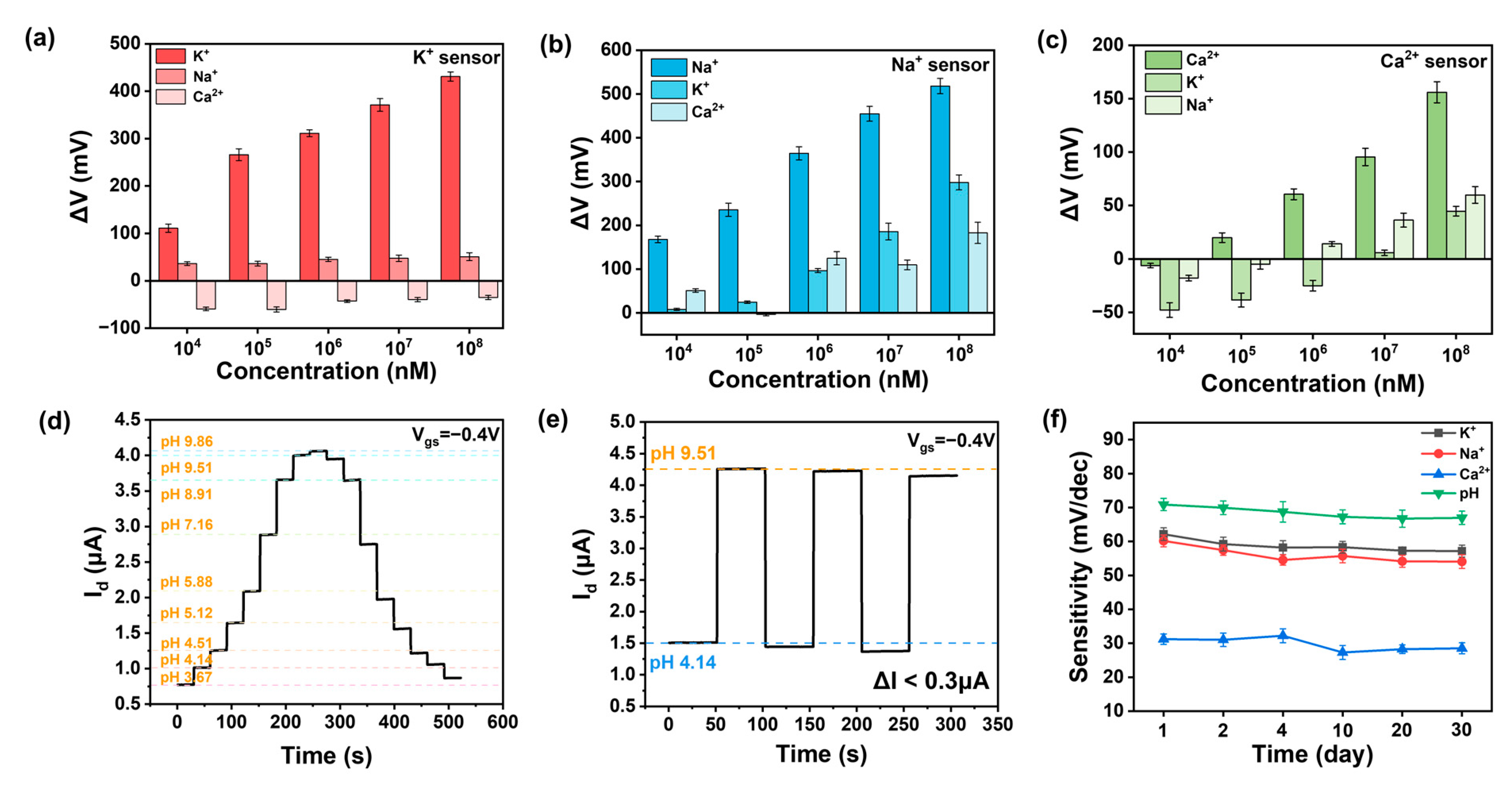
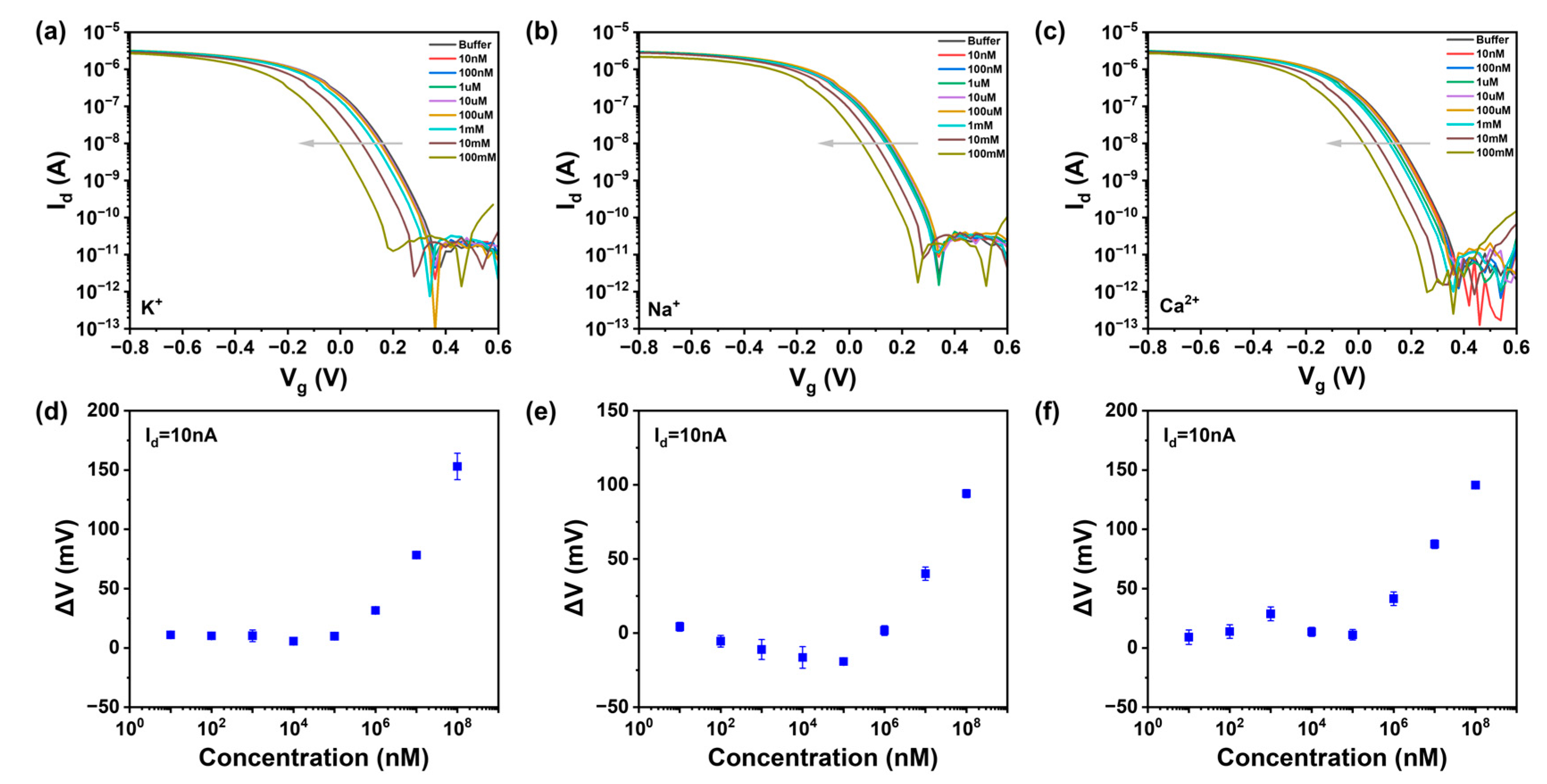
Beyond sensitivity, selectivity is another critical requirement for high-performance ion sensors. We tested the response of various functionalized ion sensors to different concentrations of other ions, as shown in
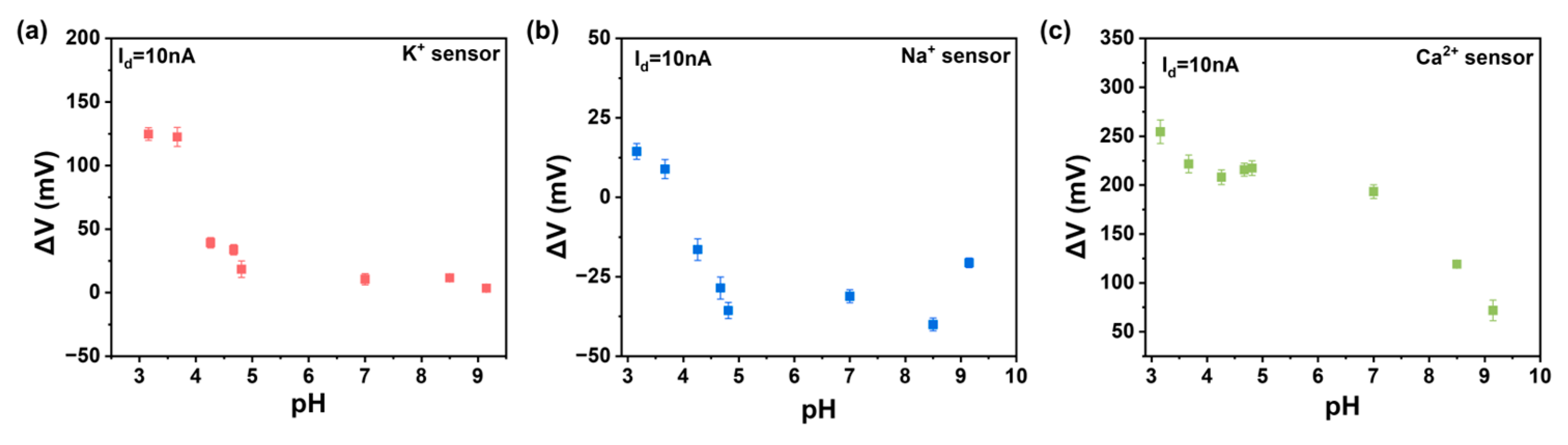
Figure 4a–c. It is evident that the response to the target ion is greater than that to other ions, thanks to the selective recognition by the ionophores in the ISM and the shielding effect of the double-layer membrane. Moreover, we tested the response of potassium and calcium ion sensors to different pH levels, as depicted in
Figure A7a–c. It can be observed that the response is significantly smaller than that to the target ion, indicating that the pH level of the solution does not affect the results of ion detection. We define the selectivity of the sensor as the ratio of the concentration of non-specific ions required to achieve the same
Vref value to the concentration of specific ions [
31]. In the sodium-functionalized sensor, when KCl is at 10 μM, we obtained a current of 10 nA with a Δ
V of 160 mV, corresponding to a sodium chloride concentration of 10 mM. The extracted selectivity of the sodium-functionalized sensor is 1000. The aforementioned research demonstrates that the sensor has a selective response to the target ion, confirming that the response of our sensor indeed originates from the specific binding between the ionophore and the target ion, rather than the ion strength. Comparing our work with other works, we found that our ion sensor has obvious high performance in
Table 1. Our CNT FG FET is able to detect ions with high sensitivity and selectivity, mainly due to the synergistic effects of the ion-selective membrane, carbon nanotubes, and floating-gate structure.
For a reliable pH sensor, hysteresis and repeatability are also crucial. Repeatability refers to the variation in measurement results when the same measurement is repeated under identical conditions and in the same direction [
32]. During testing, the source-drain bias (
Vds) and gate voltage (
Vg) were set to −0.1 V and −0.4 V, respectively. We tested the dynamic response from pH 3.67 to 9.86 and back to 3.67, as shown in
Figure 4d. The curves essentially coincide, indicating that the pH sensor has strong anti-hysteresis capabilities. We assessed the repeatability of the CNT FET ion sensor through cyclic dynamic testing at two different pH values (pH 4.14 and pH 9.15), as depicted in
Figure 4e. The ISFET channel current showed almost no significant signal degradation (Δ
I < 0.3 μA) over three cycles of concentration change, demonstrating the device’s good repeatability. These excellent performance characteristics once again confirm the favorable performance and minimally defective stable HfO
2 sensing interface of the CNT FET ion sensor in continuous pH monitoring.
We further investigated the performance variation in the ISFET over time. Under the same bias voltage conditions, the stability of the ISFET was judged over thirty days by measuring the relationship between the response value (Δ
V) and concentration. It can be seen that the sensitivity of ion sensors decreased slightly in the first four days and then remained essentially unchanged for the following month, with a variation of less than 10% in
Figure 4f. In addition to the inherent stability of the carbon-based sensor, the outer layer of the membranes provide a stable ion shielding effect, protecting the ionophores in the inner layer from being washed away and enhancing the stability of the ion sensor [
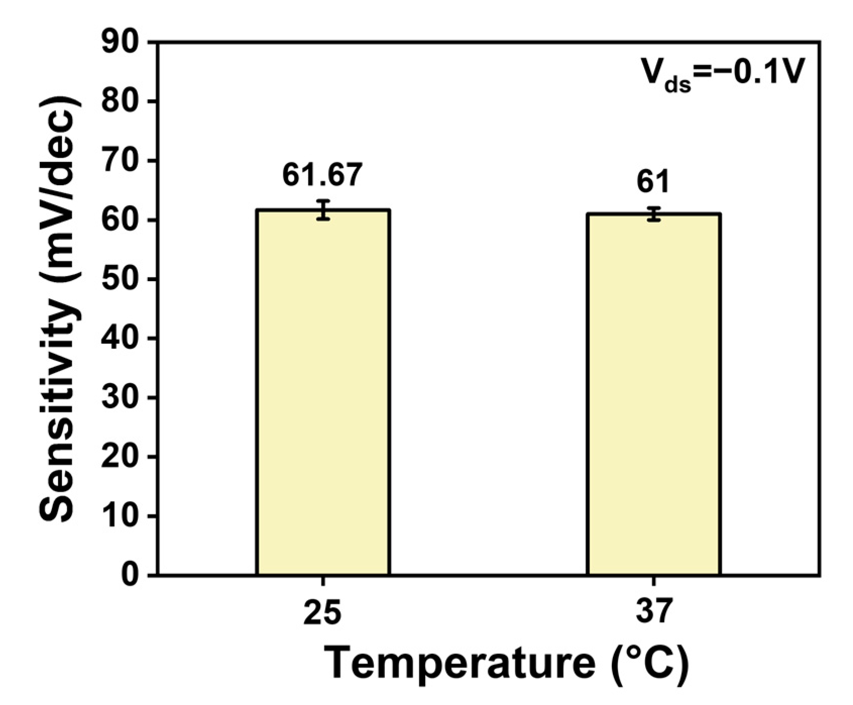
33]. The stability of the CNT FET ion sensors was satisfactory. We studied the effect of temperature on the sensing performance and found that the sensitivity did not change much when tested at 37 °C compared to 25 °C in
Figure A8. The preservation of the membrane-functionalized device is also important. A lack of moisture can cause the membrane to crack, thereby affecting the performance of the ion sensor. Therefore, the devices were stored in 100 mM of the target solution at 25 °C.
3.5. Packaged CNT FG FET Ion Sensors for Portable Analysis of Artificial Cerebrospinal Fluid
Alterations in ion concentrations within the cerebrospinal fluid (CSF) are intimately associated with the onset and progression of various neurological disorders [
5]. Monitoring these ion concentrations in the CSF can offer vital clues for the early diagnosis of neurological diseases. This study validated the potential applications of the sensor system’s for neurological disease monitoring by detecting K
+, Na
+, and Ca
2+ in aCSF. To achieve portable ion detection, an ion tester was designed, composed of a custom printed circuit board (PCB) and a microcontroller, as shown in
Figure 5a. The tester determines ion concentrations in solutions by measuring changes in potential across the sensors. The drain voltage (V
d) of the ion chip is fixed at 1.65V, while the source voltage (V
s) and gate voltage (V
g) are not fixed. The control board MCU can control the DAC1/DAC2 outputs of the acquisition board MCU to provide V
s/V
g. When the MCU outputs V
s/V
g to the source/gate of the ion chip through the internal DAC1/DAC2, the ion chip responds with nA-level currents through eight drain outputs. The multiplexer (MUX) system sequentially selects each drain channel current to the input of the operational amplifier (OPA). The nA-level response current is amplified to the mV-level voltage by the OPA and fed into the ADC input for the MCU to acquire. The MCU calculates the response current and transmits the value through the TTL serial port to the control board MCU. The control board MCU then fits the relationship between the response current and ion concentration and tests the ion concentration of the solution to be measured, displaying the ion concentration value on the LCD.
In this study, we developed a multi-region packaged CNT FET chip for the simultaneous detection of multiple ions using an ion detector. The simultaneous detection of multiple markers is very important for achieving comprehensive disease analysis. However, due to the limitations of traditional drip-coating functionalization methods, multi-modified chips often require a large chip size to isolate each region, which greatly reduces the number of chips integrated on a wafer and increases chip costs [
34]. To achieve higher integration, wire bonding and epoxy damming techniques were employed to package the CNT FET chip, similar with our previous study [
35]. Wire bonding was used to establish reliable electrical connections between the chip and external circuits, and epoxy damming was used to protect the metal wires and electrodes from liquid environments and mechanical vibrations. The packaged CNT FET chip demonstrated high uniformity and stability, with multiple channels exhibiting high consistency and linear response during the detection process. In our multi-region packaged chip design, the four small-sized CNT FG FET ion-sensing chips (with dimensions of 3.5 mm × 3.5 mm) were placed in the four regions of the PCB base, which were isolated from each other using the epoxy damming technique. Each region can be functionalized with a different ion-selective membrane separately, enabling the simultaneous detection of four distinct ions, as shown in
Figure 5b. This design allows for the use of shared biological samples for concurrent testing without the need for complex microfluidic assistance. This package process also is compatible with functionalization with different biomolecules.
Combining the ion detection system and the multi-ion packaging chip will form a portable multi-ion detector, as shown in
Figure 5c. We used the portable detector to test the concentrations of four ions in artificial cerebrospinal fluid. As seen in
Figure 3, we input the calibration curve of each ion into the internal program of the multi-ion detector. We compared the detection values of different ion concentrations in cerebrospinal fluid with theoretical values, as shown in
Figure 5d. It can be seen that in the presence of other molecules and ions, the measured ion concentrations differ from the actual concentrations by less than 5%, proving that our sensors can achieve highly sensitive, selective, and stable detection in complex samples. By combining the multi-ion package chip and the ion detector, the concentration of four ions in the solution can be detected simultaneously. The concentrations of K
+, Na
+, and Ca
2+ were 333.33 µM, 3.33 mM, and 33.33 mM, respectively, while the pH values tested were 4, 7, and 9. As the ion concentrations increased, the drain current of the CNT FET chip decreased significantly, demonstrating the excellent performance of the multi-ion packaged chip, as shown in
Figure 5e. Our portable ion detector provides a rapid, accurate, and cost-effective method for detecting multiple ion concentrations, meeting the needs of on-site, rapid ion detection.


