Abstract
Carbon-based nanocomposites coated with iron oxides were synthesized using a wet impregnation method with thermally annealed coal and an iron nitrate precursor. The influence of the thermal treatment atmosphere (air, vacuum, or nitrogen) on the morphology, structure, and magnetic properties of the nanocomposites was examined by X-ray diffraction, Raman spectroscopy, and transmission electron microscopy. It was found that the vacuum thermal treatment produced carbon-based nanocomposite containing iron oxide with the highest crystallinity, according to XRD analysis, while also inducing the greatest degree of structural defects in the carbon matrix, as evidenced by Raman analysis. Mössbauer spectroscopy confirmed that all thermal treatment methods promote the formation of the hematite phase, which was found to be the only phase formed in the air-treated nanocomposites, whereas traces of magnetite and the formation of Fe(OH)3 were detected in the vacuum- and nitrogen-treated nanocomposites, respectively. Magnetic characterization revealed that all nanocomposites exhibit ferromagnetic-like behavior, attributed to the weak ferromagnetic nature of hematite. The best magnetic response (highest saturation magnetization with the widest hysteresis loop) was observed in the vacuum-treated nanocomposites. These findings collectively demonstrate that the synthesis atmosphere plays a crucial role in tailoring the structural and magnetic characteristics of carbon-based iron oxide nanocomposites, offering pathways for their optimization in applications such as catalysis, environmental remediation, or sensing technologies.
1. Introduction
Coal remains one of the most abundant and widely distributed natural resources worldwide, with substantial reserves of anthracite and bituminous coal across multiple regions. Historically, its primary use has been as a fuel source. However, the ongoing global energy transition is transforming its role, prompting a shift toward the development of high-value materials derived from coal that meet current technological and market demands. This shift reflects the need to reduce environmental impact while maximizing the functional potential of coal in advanced applications [1,2,3]. Carbonaceous materials exhibit remarkable versatility due to their tunable chemical structure, surface area, and porosity. Their inherent chemical and thermal stability, non-toxic nature, natural abundance, and low production cost make them ideal candidates for a wide range of technological and industrial applications such as hydrogen storage, water treatment, and electrochemial CO2 reduction, etc. [4,5,6,7,8,9]. These properties can be further enhanced by incorporating into their structure uniformly distributed metal particles [10]. In particular, the integration of magnetic nanoparticles, such as iron oxides, has drawn significant attention due to their synergistic interactions with carbon [11,12,13].
Among the different iron oxide phases, hematite (α-Fe2O3) stands out due to its exceptional chemical stability, non-toxicity, and widespread availability, making it a highly promising material for various technological applications [14,15,16,17]. Its high corrosion resistance and thermodynamic stability allow for use in extreme environments, while its semiconducting nature and visible-light absorption capabilities make it valuable for photocatalysis and energy conversion [13,18]. Additionally, at the nanoscale, hematite nanoparticles exhibit unique magnetic properties, including weak ferromagnetism and high coercivity, which enhance its suitability for applications in magnetic storage and biomedical technologies. When incorporated into carbon-based composites, hematite further improves electrochemical performance, catalytic efficiency, and structural durability, making it an essential component in energy storage devices [13] and environmental remediation [19,20].
Understanding how these materials evolve under different atmospheric conditions is crucial for optimizing their structural and magnetic properties [21,22,23]. The thermal treatment atmosphere significantly influences the crystallinity, phase composition, and morphology of the nanocomposites, directly impacting their functional performance [24,25]. Variations in oxygen availability, temperature, and reactive gas composition affect the oxidation state of iron, the formation of carbon structures, and the interfacial interactions between iron oxides and carbon. Investigating these effects provides valuable insights for tailoring synthesis conditions, ultimately enhancing the performance and applicability of these materials in cutting-edge technologies [26,27,28]. The structural and morphological characteristics of iron oxide nanomaterials are highly sensitive to the atmosphere employed during thermal treatment. In a study by Slimani et al. (2021), hematite nanoparticles were synthesized under air, nitrogen, and argon atmospheres via a sol–gel route followed by thermal annealing at 500 °C. The results demonstrated that the crystallite size, phase purity, and morphology were significantly influenced by the annealing environment. Specifically, thermal treatment in nitrogen yielded smaller crystallite sizes and reduced crystallinity compared to air, indicating that inert atmospheres hinder grain growth and affect phase formation pathways. The authors also observed variations in surface area and magnetic behavior, suggesting a direct correlation between the synthesis atmosphere and the functional properties of the nanomaterials [29]. Similarly, Kundu et al. (2024) investigated the thermal decomposition of ferrocene under different atmospheres (air, O2, and N2), revealing that distinct iron-containing phases could be selectively obtained by simply adjusting the gaseous environment. Under air and O2, pure hematite (α-Fe2O3) was formed, whereas N2 conditions favored the formation of mixed phases including Fe3C (cementite) and α-Fe2O3, attributed to limited oxidation and carbon incorporation. These findings confirm that the thermal atmosphere plays a pivotal role not only in phase composition but also in particle morphology, crystallite size, and surface characteristics [30]. In another related study, Alcalá and Real (2006) showed that oxidizing atmospheres such as air promote the formation of hematite (α-Fe2O3), while reducing atmospheres (e.g., N2/H2) stabilize phases like magnetite (Fe3O4) and even metallic iron (α-Fe), with the silica matrix acting as a diffusion barrier that favors metastable phase retention and limits crystal growth [31]. Complementarily, da Cunha et al. (2021) observed that sequential calcination in air followed by hydrogen reduction transformed oxide nanoparticles into their metallic counterparts (Co0 and Fe0), significantly altering dispersion, crystallinity, and support interactions, factors that directly impacted their catalytic performance and morphological uniformity [32]. More recently, Vale et al. (2025) reported a dual-atmosphere thermal approach in which Fe3+ impregnated into MCM-48 mesoporous silica was first calcined in air to form hematite, and then annealed in argon at 800 °C to generate a hematite–magnetite mixture. This stepwise treatment not only preserved the spherical morphology and mesoporous order but also enhanced photoacoustic signal performance due to improved thermal confinement and FeNPs distribution [33]. Collectively, these studies highlight that carefully controlled thermal environments are essential to tune nanoparticle size, phase stability, and functional properties of metal–silica nanocomposites for applications ranging from catalysis to biomedical imaging. In this work, we have synthesized iron oxides-coated carbon nanocomposites by a simple wet impregnation method. A comprehensive characterization by scanning electron microscopy (SEM), transmission electron microscopy (TEM), X-ray diffraction (XRD), Raman and Mössbauer spectroscopy, and magnetometry has allowed us to investigate the influence of the synthesis atmosphere (air, vacuum, or N2) on the structural and magnetic properties of these heterostructures.
2. Materials and Methods
2.1. Thermal Annealing of Amorphous Mineral Coal in an Inert Atmosphere
The mineral coal used in this study was sourced from the Fortuna mine (Departamento de Santander, Colombia), and classified as semi-anthracite according to ASTM D388 [34]. The proximate analysis of the coal was carried out in accordance with ASTM methods D3174 for ash content (8.83%) [35], D3172 for fixed carbon (80.16%) [36], D3175 for volatile matter (10.41%) [37], D5865 for calorific value (14,033 BTU/lb), and D4239 for sulfur content (0.69%) [38,39]. An ultimate analysis to determine the nitrogen (1.48%), hydrogen (3.15%), and carbon (78.45%) content was also conducted based on ASTM D5373 [40]. Subsequently, 8 g of the coal sample was placed in a rectangular magnesium oxide crucible and placed inside a Nabertherm LHT 02/18 high-temperature furnace. The sample was heated to 1700 °C at a rate of 10 °C/min under a constant argon flow at 150 L/h and then held at this temperature for 2 h. After the heating process, the sample was allowed to cool inside the furnace and was retrieved once it reached room temperature.
2.2. Synthesis of Carbon-Based Nanocomposites Coated with Iron Oxides
Iron deposition was carried out using a wet impregnation method. A quantity of 500 mg of the annealed mineral coal (AMC) and 50 mL of water obtained by Milli-Q system were placed in a 300 mL beaker at room temperature. The mixture was stirred at 800 rpm for 40 min. Subsequently, 11 mL of a 0.09 M Fe(NO3)3∙9H2O solution was added to the carbon suspension, resulting in an iron loading of 10 wt%. The mixture was stirred at 800 rpm for an additional 2 h at room temperature. Afterward, the suspension was dried in air at 70–80 °C using a heating plate equipped with a thermocouple, and the resulting material was divided into three equal portions. One portion was subjected to thermal treatment at 500 °C for 1 h, with a heating rate of 5.0 °C/min, in a tubular furnace (MTI Corporation GSL1500X) in air. The other two portions were treated under the same thermal conditions but in different environments: one in reduced air pressure (~0.09 bar), initially achieved using a mechanical pump and subsequently maintained as a static vacuum after sealing the system and the other in a dynamic N2 atmosphere (0.5 mL/min). The resulting materials were labeled as ACN 10, VCN 10, and NCN 10, where A, V, and N denote the atmospheres used during synthesis. The sample without iron was labeled CN. A schematic representation of the synthesis process is shown in Figure 1.
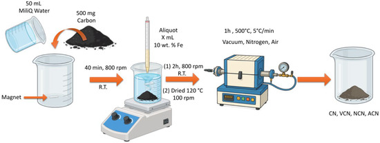
Figure 1.
Schematic representation of the synthesis procedure for FexOy/C nanocomposites.
2.3. Sample Characterization
Structural and phase analysis of the samples was performed by X-ray diffraction (XRD) using a Bruker D8 Advance Eco diffractometer with CuKα radiation (λ = 0.15418 nm, 40 kV, 25 mA). Data were collected at room temperature and over a 2θ angle range of 10–80°, with a scan rate of 0.01°. Crystalline phase detection was carried out by comparing the obtained patterns with reference data from the Inorganic Crystallography Open Database (COD), using the X’pert HighScore Plus software (Malvern Panalytical B.V., Almelo, The Netherlands)). Local morphological, crystalline and compositional analysis were performed by scanning electron microscopy (SEM) using a Phenom Pro X microscope, equipped with an energy-dispersive X-ray spectroscopy (EDS) detector from Oxford Instruments, and by high-resolution transmission electron microscopy (HRTEM) in a Thermo Fisher Scientific image-corrected Titan 60–300 microscope operating at 300 kV. For these experiments, the samples were ultrasonically dispersed in isopropyl alcohol and drop-cast onto an ultrathin holey carbon-coated copper grid. A complementary analysis of the type of iron oxides presented in the samples was performed through Raman and Mössbauer experiments. Raman spectra were recorded using a Jasco RMS 4500 Raman spectrometer, employing a 532 nm (2.34 eV) laser with a power below 2 mW to prevent overheating. Mössbauer spectra were acquired at room temperature using a constant-acceleration spectrometer with a 57Co/Rh radioactive source (~5 mCi). The spectra were fitted using the MOSFIT program [41] and the isomer shift (IS) was referenced to α-Fe. Finally, magnetic characterization was performed by measuring the hysteresis loops of the specimens using the vibrating sample magnetometer (VSM) module of a Physical Properties Measurement System (PPMS) from Quantum Design®. The metal content of the samples was determined using an Agilent 5110 VDV ICP-OES instrument. The measurements were carried out in axial view mode with four replicates per sample. The integration time was set to 6 s. A Seaspray nebulizer coupled with a double-pass cyclonic spray chamber was used for sample introduction. The operating conditions included an RF power of 1200 W, a peristaltic pump speed of 12 rpm, and the following gas flow rates: plasma gas at 12 L/min, nebulizer gas at 0.70 L/min, and auxiliary gas at standard instrument settings. Calibration curves were obtained using certified standard solutions, and all measurements were performed under optimized and stabilized plasma conditions to ensure accuracy and reproducibility.
3. Results and Discussion
3.1. Structural Analysis from X-Ray Diffraction
The crystalline structure of the samples was analyzed using XRD. Both the annealed coal and the carbon-based nanocomposites coated with iron oxides were examined to identify the present phases. Figure 2 shows the diffractograms and structural parameters of the samples. In Figure 2a, the CN sample exhibits the characteristic peaks of graphite and amorphous carbon at 26.5°and approximately 42.3°, which is consistent with data reported in COD 9011577 [42]. Additional peaks of lower intensity are observed, corresponding to quartz (20.8°, 26. 5°, 36.4°, 40.2°, 42.3°, 50°, 68°, COD 9011493) [43] and mullite (25.9°, 26.1°, 30.9°, 33.1°, 35.1°, 36.9°, 39.1°, 40.8°, 42.5°, 60.5°, COD 9001321) [44]. Furthermore, it is important to note that the peaks widths around 26° and 42° are indicative of turbostratic carbon, a structure composed of both amorphous carbon and crystalline graphite phases, where each phase contributes carbon atoms in sp3 and sp2 hybridization states, respectively [45]. These results indicate that the carbon structure includes both amorphous carbon, evidenced by broad peaks, and crystalline graphite, along with silica and alumina.
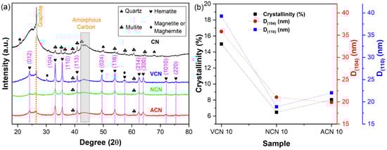
Figure 2.
Structural analysis of samples subjected to thermal treatment under vacuum, nitrogen, and air atmospheres. (a) XRD patterns and (b) variation in hematite crystal size along the (104) and (110) directions, and estimated crystallinity of each nanocomposite.
In contrast, the sample thermally treated under vacuum (VCN 10) shows more intense peaks in the (104) and (110) directions, characteristic of the hematite phase (α-Fe2O3, peaks at 24.1°, 33.1°, 35.6°, 40.8°, 49.4°, 54.0°, 62.4°, 63.9°, and 71.9°, COD 2108027) [46], along with the amorphous and crystalline carbon phases. For the samples treated in nitrogen and air (NCN 10, ACN 10), a similar behavior was observed, although the intensities of the characteristic peaks vary. The NCN 10 sample shows the lowest intensity of hematite peaks, which can be attributed to the nitrogen environment, possibly limiting the crystallization of hematite. It should also be noted that thermal treatment may promote the formation of a second phase, such as magnetite (Fe3O4) and/or maghemite (γ-Fe2O3) in small amounts. However, due to the identical inverse spinel structure of these phases, they are difficult to distinguish by XRD analysis alone [47]. To complement this study, Mössbauer spectroscopy was conducted (vide infra).
Using Bragg’s law and Scherrer’s method [48,49,50,51,52], the crystal size and lattice parameters of hematite were calculated and reported in Table 1. No significant differences in lattice parameters were found across the different thermal treatments, suggesting that the crystal structure of hematite remains stable under the employed atmospheres.

Table 1.
Structural parameters of hematite and crystallinity percentage of the nanocomposites.
Figure 2b presents the crystal size for hematite along the (104) and (110) directions (denoted as D(104) and D(110), respectively). The VCN 10 sample exhibits substantially larger crystal sizes compared to the NCN 10 and ACN 10 samples, indicating that both nitrogen and air atmospheres (the latter composed of ~78 wt.% nitrogen) constrains crystal growth. Given the amorphous nature of coal, the crystallinity of the CN-hematite nanocomposites, defined as the mass fraction of the crystalline regions within the material and representative of long-range structural order, was determined combining the reference intensity ratio (RIR) and degree of long-range (DOC) methods [53,54,55]. The RIR method relates crystallinity to amorphous phase content, while the DOC method quantifies crystalline phase directly. The crystallinity analysis revealed that the vacuum-treated nanocomposites reached the highest crystallinity (15%), which is nearly double that observed in the nitrogen- (6.5%) and air-treated (8.0%) samples. This trend mirrors the behavior observed for the crystal size (Figure 2b), suggesting that higher crystallinity facilitates the formation of larger hematite nanocrystals.
3.2. Electron Microscopy Analysis
Following the structural analysis, a microscopic examination by SEM and TEM experiments was carried out to evaluate the influence of different thermal treatment atmospheres on morphology and crystallinity of the nanocomposites. Figure 3 presents SEM images and EDS elemental mapping results, including atomic and weight percentage quantification, for both untreated coal powders (CN) and the synthesized nanocomposites. The SEM image of the CN sample (Figure 3a) shows micrometer-sized grains with irregular shapes and varying sizes. According to EDS analysis (Figure 3e), the coal grains extracted from the mine are primarily composed of carbon and oxygen, as expected, with trace amounts of nitrogen, aluminum, and silicon. The SEM image of the VCN 10 sample (Figure 3b) reveals that the iron-containing compound forms a coating on the surface of a carbon grain of tens of microns in size, as well as on adjacent smaller grains, as confirmed by the elemental map in Figure 3f. For the NCN 10 sample, the SEM image (Figure 3c) and EDS mapping (Figure 3g) show carbonaceous grains with generally smaller sizes compared to the CN and VCN 10 samples. Iron-based compounds are presents as surface deposits, though less homogeneously distributed. Finally, in the ACN 10 sample, the SEM image (Figure 3d) demonstrates that the thermal treatment in air results in a significant reduction in the size of the carbon-based grains, with dimensions ranging from a few microns down to hundreds of nanometers. EDS analysis (Figure 3h) indicates the presence of iron and oxygen on the carbon surface, but no evidence of a continuous coating over the entire grain was observed.
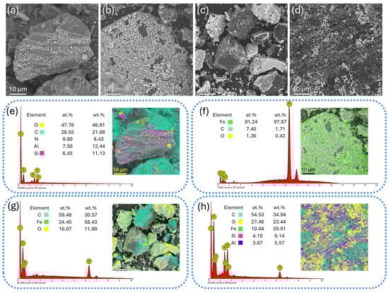
Figure 3.
Morphology and elemental composition of the samples analyzed by SEM and EDS experiments. SEM images of (a) CN, (b) VCN 10, (c) NCN 10, and (d) ACN 10 samples. EDS compositional maps and elemental quantification of (e) CN, (f) VCN 10, (g) NCN 10, and (h) ACN 10 samples, highlighting the distribution of carbon, oxygen, iron, and trace elements.
Thus, from the SEM-EDS analysis, it can be concluded that vacuum thermal treatment favors the effective deposition of iron oxide particles onto the carbon grain surface using the wet impregnation method. In contrast, thermal treatment in air promotes a notable reduction in the particle size of the carbon support.
Figure 4 displays representative HRTEM images, along with a series of fast Fourier Transformed (FFT) images extracted from nanocrystals attached to the carbon nanostructures, in order to analyze the morphology of the nanocomposites at the nano- and atomic scale. Figure 4a shows an HRTEM image of a carbon nanostructure from the CN sample. Lattice fringes with very short-range order can be seen embedded within an amorphous matrix, indicating that the untreated coal is predominantly amorphous, consistent with the XRD results. In contrast, the HRTEM images of the thermally treated samples—VCN 10 (Figure 4c), NCN 10 (Figure 4f), and ACN 10 (Figure 4i)—demonstrate that all three thermal treatment conditions promote partial crystallization of the carbon phase. The VCN 10 sample reveals the formation of onion-like carbon nanostructures, similar to that schematically represented in Figure 4b [56,57]; the NCN 10 sample shows a mixture of curved-graphitic and onion-like carbon nanostructures; and the ACN 10 sample displays curved-graphitic carbon nanostructures. In all treated samples, small nanocrystals with sizes ranging from approximately 8 to 12 nm were identified in close proximity to the carbon nanostructures (Figure 4d,g,j). These nanocrystals were attributed to the hematite phase, based on electron diffraction analysis carried out on FFT images (see Figure 4e,h,k). These results confirm that the nanoscale morphology of the nanocomposites is consistent with the macroscopic structural trends observed in the XRD analysis.
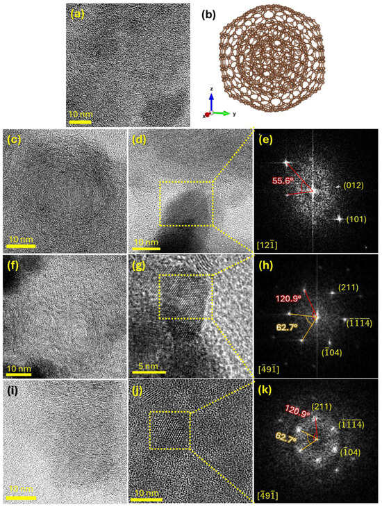
Figure 4.
Morphological and structural analysis of the synthetized samples performed by TEM. HRTEM images acquired on carbon nanostructures of the (a) CN, (c) VCN 10, (f) NCN 10, and (i) ACN 10 samples. (b) Model of the nano-onion structure. HRTEM images recorded on hematite nanocrystals of the (d) VCN 10, (g) NCN 10, and (j) ACN 10 samples. (e,h,k) are FFT images reconstructed from the nanocrystals highlighted in the HRTEM images of (d), (g), and (j), respectively.
3.3. Mössbauer and Raman Spectral Analysis
To identify the type of iron oxides present in each FexOy/C composite, room-temperature Mössbauer spectroscopy measurements were performed, as shown in Figure 5. Each spectrum exhibits well-defined magnetic hyperfine splitting, which can be accurately fitted using three sextets and one doublet. In the ACN 10 sample (Figure 5a), the spectral shape indicates that the composition consists of a single phase attributed to hematite (α-Fe2O3). This phase is specifically associated with Fe3+ ions occupying octahedral interstices formed by oxygen atoms, representing the most thermodynamically stable form of iron oxide [58,59]. For the VCN 10 sample (Figure 5b), two of the sextets correspond to the magnetite (Fe3O4) phase—one associated with Fe3+ ions in tetrahedral (A) sites and the other with Fe2+/Fe3+ ions in octahedral (B) site [60]. Additionally, another sextet is associated in greater proportion to hematite (α-Fe2O3) phase. In the NCN 10 sample (Figure 5c), the spectrum reveals a sextet corresponding to the hematite phase and a doublet attributed to amorphous iron hydroxide (Fe(OH)3). The Mössbauer parameters obtained from the spectral fitting are summarized in Table 2. The IS, QS, and BHF values obtained for the fitted hematite phase are comparable with those reported in previous studies [61]. These values can be influenced by several factors, including the crystal size of iron oxide [62], the formation of layers leading to crystallization on the surface and within the carbonaceous material [58], and methodological aspects such as the sample preparation method and the thermal treatments to which the samples were subjected [59].
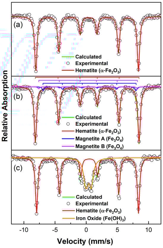
Figure 5.
Mössbauer analysis for each sample. (a) ACN 10, (b) VCN 10, and (c) NCN 10. The experimental data is presented as open circles and the calculated fit in brown color line.
Table 2.
Hyperfine parameters obtained from the room-temperature Mössbauer spectra for all the FexOy/C composites: isomer shift (IS), quadrupole shift (QS), magnetic hyperfine field (BHF) at iron nuclei, and relative area (RA) of the components.
For the samples shown in Figure 5, the hyperfine parameters are slightly lower than those reported for ideal hematite. This discrepancy can be attributed to the possibility of non-homogeneous crystallization, leading to variations in particle size distribution [58]. Regarding the IS values, the results align with those typically observed for iron ions in high oxidation states and high-spin configurations [63], specifically Fe3+. Additionally, the negative QS values indicate a weak ferromagnetic character of hematite, which is consistent across all samples analyzed in this study, as expected for this phase [64,65].
As is observed in Figure 5a, the hematite phase obtained under an air atmosphere (ACN 10 sample) exhibited a relative area percentage of 100%, reinforcing the thermodynamic stability of this phase under oxidizing conditions. In contrast, for the magnetite (Fe3O4) phase in the VCN 10 sample (Figure 5b), the fitted relative areas suggest that site B occupies twice the area of site A, which is characteristic of stoichiometric magnetite. Notably, a secondary phase was detected only in the NCN 10 sample (Figure 5c), synthesized under an N2 atmosphere. This phase is likely associated with the formation of the Fe(OH)3.
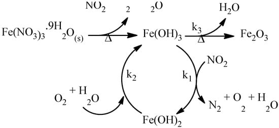
The Mössbauer parameters obtained in this study closely align with those reported by Euler and co-workers [66], who proposed the formation of this intermediate species during the decomposition of Fe(NO3)3⋅9H2O into Fe2O3. According to this mechanism, the decomposition process provides both reducing (NO2) and oxidizing (O2) agents, maintaining their concentrations relatively constant in a static N2 atmosphere. NO2 facilitates the formation of reduced iron in the Fe(OH)2 form, which subsequently re-oxidizes to Fe(OH)3 in the presence of oxygen and water molecules (see Scheme 1).
Scheme 1.
Thermal decomposition process of hydrated iron(III) nitrate nonahydrate in a static N2 atmosphere. Adapted from reference [66].
In our system, the absence of NO2, O2, and H2O, due to the use of a continuous N2 flow, prevents the reduction and re-oxidation processes between the Fe(OH)3 and Fe(OH)2 species. As a result, the transformation of Fe(OH)3 into Fe2O3 occurs through a kinetically favorable pathway. The presence of the Fe(OH)3 phase is evidenced by broad, low-intensity peaks in the XRD pattern, which are characteristic of its amorphous nature. In contrast, the presence of magnetite as a secondary phase in the VCN 10 sample (see Figure 5b) can be attributed to the conditions in a static vacuum atmosphere, where the formation of Fe(OH)2 is slightly favored due to the presence of reducing agents such as NO2 [66]. This adjustment was made to facilitate the accurate identification of other iron sites in the spectra.
The Raman spectra of all samples are shown in Figure 6. These spectra confirm that the majority phase corresponds to hematite; with six vibrational modes identified in the Raman region between 200 and 800 cm−1. These vibrational modes correspond to: A1g phonon modes at approximately 222.2 cm−1 and 494.2 cm−1; Eg phonon modes at around 290.3 cm−1, 404.5 cm−1, and 608.6 cm−1; the relatively weak band around 656.7 cm−1 may arise from disorder-activated modes or longitudinal optical phonons consistent with partial structural disorder in hematite [67,68,69,70,71,72]. Our findings are consistent with previous reports, confirming the presence of these six vibrational modes. Additionally, the presence of a very weak vibrational band observed at around 656.7 cm−1 suggests structural disorder in the crystalline structure of hematite. No vibrational modes associated with Fe3O4 and Fe(OH)3 structures were observed, probably due to low concentration of these phases. Furthermore, two vibrational bands at around 1350 cm−1 and 1596 cm−1 (see Figure 6b,c) are attributed to carbonaceous materials. The D-band is observed to be prominent in all samples, while the G-band exhibits lower intensity, comparable to that of the D-band (see Figure 6c). The D-band is forbidden in a perfect graphitic material and becomes active only in the presence of disorder. The intensity ratio (ID/IG) is commonly used to indicate the degree of crystallinity in carbonaceous materials. Based on the ID/IG ratio, all samples exhibit a high degree of defects and amorphous carbon, which agrees with XRD and TEM analysis. Additionally, based on the synthesis conditions, a shift to lower wave numbers is observed for samples ACN 10 and NCN 10 compared to VCN 10 and CN. This red-shift may indicate a reduction in graphitic domain size, increased structural disorder, or changes in local strain induced by different atmospheric conditions during synthesis. Regarding ID/IG ratio, the highest value was observed for the VCN 10 sample, significantly exceeding those of the ACN 10 (5.15) and NCN 10 (2.30), and even the CN (1.02) sample. These results suggest that the vacuum thermal treatment induces the formation of nanocomposites with a higher degree of structural defects in the carbon phase.
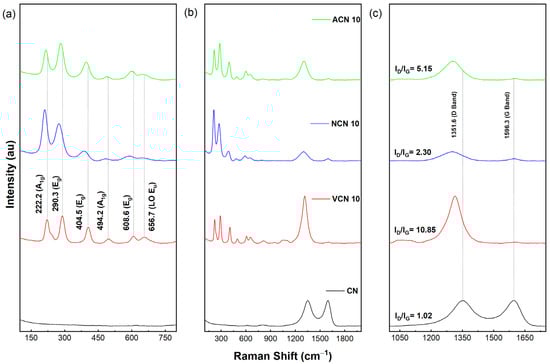
Figure 6.
Raman spectra of all samples. Raman shift between (a) 150–750 cm−1, (b) 300–1800 cm−1, and (c) 1050–1650 cm−1.
3.4. Magnetic Analysis
Figure 7 shows the magnetization (M) curves as a function of the applied magnetic field (H), obtained from room-temperature VSM experiments to investigate the magnetic behavior of the nanocomposites. All samples exhibit very narrow hysteresis loops, with a very low saturation magnetization (Ms), and low remanent magnetization (Mr) and coercive field (Hc). This magnetic behavior is governed by the weak ferromagnetic nature of the hematite phase. At room temperature, hematite exhibits antiferromagnetic order with a small canted magnetic moment, which results in a weak ferromagnetic response [64,65]. The antiferromagnetic character of hematite is evidenced by the linear increase in magnetization in the reversible part of the hysteresis loop. For this reason, to estimate Ms of each nanocomposite, the hysteresis loops were corrected to subtract the antiferromagnetic contribution, considering that corrected magnetization (Mcorr) can be estimated as Mcorr = M − NH, where N is the slope of the linear magnetization increase at high magnetic fields. Additionally, Ms normalized to the iron content (denoted here as M’s) was estimated for all samples, considering that the resulting carbon-based nanocomposites contain 9.77 0.06 wt.% of Fe according to inductively coupled plasma mass spectroscopy (ICP-MS) results, which is very close to the expected value (10 wt.%). All the relevant magnetic parameters are listed in Table 3.
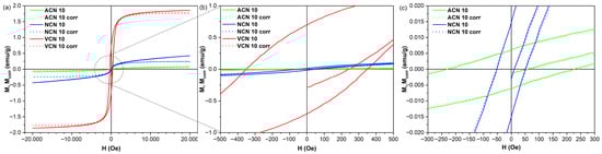
Figure 7.
(a) Magnetization hysteresis loops of the synthesized composites. Zooming in (b,c) improves the visualization of the hysteretic behavior of the magnetization.
Table 3.
Magnetic parameters of the nanocomposites determined by VSM measurements.
Regarding saturation magnetization, we found that both ACN 10 (virtually pure hematite) and NCN 10 (70.6 wt.% hematite) samples exhibited M’s values of 0.4 and 2.4 emu/g, respectively. These values fall within the same order of magnitude as those reported for hematite single crystals and nanoparticles (between 0.05 and 3 emu/g), a value that is highly sensible to different factors such as grain size, thermal treatment, and surface spin disorder [64,65]. In the case of NCN 10 sample, the Fe(OH)3 phase, which has an antiferromagnetic behavior at room temperature [73,74,75], contributed to an increased slope in the magnetization curve. The VCN sample showed the highest saturation magnetization (M’s = 17.7 emu/g), which can be attributed to the presence of magnetite nanoparticles in the nanocomposite, which present ferrimagnetic behavior with a saturation magnetization ranging from 41 to 80 emu/g [76]. It is important to note that all samples show non-negligible remanent magnetization and coercive field values, indicating the absence of superparamagnetic behavior. This can be attributed to the crystal size of the synthesized hematite phase, which exceeds the critical size threshold for superparamagnetism, estimated to be approximately 8–10 nm [77,78,79].
4. Conclusions
This study demonstrated that the thermal treatment atmosphere is a critical parameter influencing the structural and magnetic properties of iron oxides-coated carbon nanocomposites. Processing under vacuum conditions significantly enhanced crystallinity, with the vacuum-treated sample exhibiting approximately 15% hematite crystallinity, compared to ~8% under air and ~6.5% under nitrogen atmospheres. Furthermore, Mössbauer spectroscopy confirmed that the air-treated composite predominantly consisted of thermodynamically stable hematite, while the vacuum-treated composite contains a minor magnetite fraction, and the nitrogen-treated sample exhibited a mixed phase of hematite and amorphous iron hydroxide. These variations in phase composition and crystallinity directly impacted the magnetic behavior, with the vacuum-treated nanocomposites showing a well-defined ferromagnetic response, while the air- and nitrogen-treated samples exhibited only weak ferromagnetism.
Overall, these findings underscore the importance of tailoring the synthesis atmosphere to optimize the structural and magnetic properties of carbon-based iron oxide nanocomposites. By elucidating the influence of processing conditions in phase evolution and microstructural order, this work provides valuable insights for the rational design of advanced materials for applications such as environmental remediation, and energy conversion. The integrated approach presented herein paves the way for further exploration and development of high-performance nanocomposite systems, wherein precise control over the thermal treatment environment is paramount to achieving the targeted functional properties.
Author Contributions
Conceptualization, M.M. and R.V.; methodology, D.H.-M., M.A.M.-F., J.B., J.A.T., M.M.-A. and C.M.; formal analysis, M.A.M.-F., L.M., L.A.R., J.A.T., C.M., M.N.C., E.M.-V. and M.M.; resources, E.M.-V. and M.N.C.; data curation, M.A.M.-F.; writing—original draft preparation, E.M.-V., M.M., and R.V.; writing—review and editing, L.M., L.A.R., C.M., M.N.C., E.M.-V., M.M. and R.V.; visualization, E.M.-V., M.M. and R.V.; supervision, M.M. and R.V.; project administration, L.A.R.; funding acquisition, L.M., L.A.R., E.M.-V., R.V. and M.M. All authors have read and agreed to the published version of the manuscript.
Funding
This research was funded by the Universidad del Valle and the Ministerio de Ciencia, Tecnología e Innovación—Minciencias, grant number CD 82045 CT ICETEX 2022-0785.
Data Availability Statement
The data presented in this study are available on request from the corresponding authors.
Acknowledgments
The authors acknowledge the use of instrumentation as well as the technical advice provided by the National Facility ELECMI ICTS, node «Laboratorio de Microscopias Avanzadas (LMA)» at «Universidad de Zaragoza». The authors also acknowledge the Servicio Geológico Colombiano for providing the coal samples used in this study, as part of the project identified by code 1001563.
Conflicts of Interest
The authors declare no conflicts of interest.
References
- Agrawal, A. Technological Advancements in Cokemaking. Miner. Process. Extr. Metall. Rev. 2025, 46, 268–283. [Google Scholar] [CrossRef]
- Yadav, R.; Sharma, A.K.; Sharma, S. Advance Development in Natural Graphite Material and Its Applications: A Review. Mining Metall. Explor. 2025, 42, 361–385. [Google Scholar] [CrossRef]
- Bustamante Ortega, P.E.; Molano García, R.E.; Sánchez Maya, O.; López Rodríguez, J.F.; Londoño, T.A. Mineria Del Carbon En Colombia. Transformando El Futuro de La Industria; Ministerio: Bogotá, Colombia, 2021. [Google Scholar]
- Xia, G.; Habibullah; Xie, Q.; Huang, Q.; Ye, M.; Gong, B.; Du, R.; Wang, Y.; Yan, Y.; Chen, Y.; et al. Recent Progress in Carbonaceous Materials for the Hydrogen Cycle: Electrolytic Water Splitting, Hydrogen Storage and Fuel Cells. Chem. Eng. J. 2024, 495, 153405. [Google Scholar] [CrossRef]
- Sereda, G.; Uddin, M.T.; Wente, J. Computational Exploration of Functional Nanoscale Carbonaceous Materials. Curr. Nanosci. 2022, 18, 478–486. [Google Scholar] [CrossRef]
- Hu, S.; Qin, L.; Yi, H.; Lai, C.; Yang, Y.; Li, B.; Fu, Y.; Zhang, M.; Zhou, X. Carbonaceous Materials-Based Photothermal Process in Water Treatment: From Originals to Frontier Applications. Small 2024, 20, 2305579. [Google Scholar] [CrossRef]
- You, P.Y.; Kamarudin, S.K. Recent Progress of Carbonaceous Materials in Fuel Cell Applications: An Overview. Chem. Eng. J. 2017, 309, 489–502. [Google Scholar] [CrossRef]
- Tang, Z.; Zhou, S.; Huang, Y.; Wang, H.; Zhang, R.; Wang, Q.; Sun, D.; Tang, Y.; Wang, H. Improving the Initial Coulombic Efficiency of Carbonaceous Materials for Li/Na-Ion Batteries: Origins, Solutions, and Perspectives. Electrochem. Energy Rev. 2023, 6, 8. [Google Scholar] [CrossRef]
- Li, L.; Huang, Y.; Li, Y. Carbonaceous Materials for Electrochemical CO2 Reduction. EnergyChem 2020, 2, 100024. [Google Scholar] [CrossRef]
- Channabasavana Hundi Puttaningaiah, K.P. Innovative Carbonaceous Materials and Metal/Metal Oxide Nanoparticles for Electrochemical Biosensor Applications. Nanomaterials 2024, 14, 1890. [Google Scholar] [CrossRef]
- Văduva, M.; Nila, A.; Udrescu, A.; Cramariuc, O.; Baibarac, M. Nanocomposites Based on Iron Oxide and Carbonaceous Nanoparticles: From Synthesis to Their Biomedical Applications. Materials 2024, 17, 6127. [Google Scholar] [CrossRef]
- Mallakpour, S.; Khadem, E. Carbon Nanotube–Metal Oxide Nanocomposites: Fabrication, Properties and Applications. Chem. Eng. J. 2016, 302, 344–367. [Google Scholar] [CrossRef]
- Yu, S.; Hong Ng, V.M.; Wang, F.; Xiao, Z.; Li, C.; Kong, L.B.; Que, W.; Zhou, K. Synthesis and Application of Iron-Based Nanomaterials as Anodes of Lithium-Ion Batteries and Supercapacitors. J. Mater. Chem. A 2018, 6, 9332–9367. [Google Scholar] [CrossRef]
- Gurudayal; Bassi, P.S.; Sritharan, T.; Wong, L.H. Recent Progress in Iron Oxide Based Photoanodes for Solar Water Splitting. J. Phys. D Appl. Phys. 2018, 51, 473002. [Google Scholar] [CrossRef]
- Ajinkya, N.; Yu, X.; Kaithal, P.; Luo, H.; Somani, P.; Ramakrishna, S. Magnetic Iron Oxide Nanoparticle (IONP) Synthesis to Applications: Present and Future. Materials 2020, 13, 4644. [Google Scholar] [CrossRef]
- Nandhini, G.; Shobana, M.K. Influence of Phytochemicals with Iron Oxide Nanoparticles for Biomedical Applications: A Review. Polym. Bull. 2023, 80, 11715–11758. [Google Scholar] [CrossRef]
- Aragaw, T.A.; Bogale, F.M.; Aragaw, B.A. Iron-Based Nanoparticles in Wastewater Treatment: A Review on Synthesis Methods, Applications, and Removal Mechanisms. J. Saudi Chem. Soc. 2021, 25, 101280. [Google Scholar] [CrossRef]
- Jiao, W.; Shen, W.; Rahman, Z.U.; Wang, D. Recent Progress in Red Semiconductor Photocatalysts for Solar Energy Conversion and Utilization. Nanotechnol. Rev. 2016, 5, 135–145. [Google Scholar] [CrossRef]
- Harak, C.; Satpute, D.; Kadam, V.; Kolhe, N.; Wade, A.; Balgude, S.; Mardikar, S.; Balgude, S.; Pawar, H. Morphology Controlled Fabrication of Fe2O3/GCN Composites: A Comparative Study of Hydrothermal and Sonochemical Synthesis Methods for Efficient Sunlight Driven Photocatalysis for Environmental Remediation. Emergent Mater. 2023, 6, 1797–1807. [Google Scholar] [CrossRef]
- Benedet, M.; Barreca, D.; Rizzi, G.A.; Maccato, C.; Wree, J.-L.; Devi, A.; Gasparotto, A. Fe2O3-Graphitic Carbon Nitride Nanocomposites Analyzed by XPS. Surf. Sci. Spectra 2023, 30, 24021. [Google Scholar] [CrossRef]
- Nikolić, V.N.; Tadić, M.; Panjan, M.; Kopanja, L.; Cvjetićanin, N.; Spasojević, V. Influence of Annealing Treatment on Magnetic Properties of Fe2O3/SiO2 and Formation of ε-Fe2O3 Phase. Ceram. Int. 2017, 43, 3147–3155. [Google Scholar] [CrossRef]
- Brontowiyono, W.; AbdulHussein, W.A.; Smaisim, G.F.; Mahmoud, M.Z.; Singh, S.; Lafta, H.A.; Hussein, S.A.; Kadhim, M.M.; Mustafa, Y.F.; Aravindhan, S. Annealing Temperature Effect on Structural, Magnetic Properties and Methyl Green Degradation of Fe2O3 Nanostructures. Arab. J. Sci. Eng. 2023, 48, 375–382. [Google Scholar] [CrossRef]
- Mansilla, M.V.; Zysler, R.; Fiorani, D.; Suber, L. Annealing Effects on Magnetic Properties of Acicular Hematite Nanoparticles. Phys. B Condens. Matter 2002, 320, 206–209. [Google Scholar] [CrossRef]
- Hua, Y.; Wang, W.; Gao, J.; Li, N.; Qu, Z. A Study on the Effects of Vacuum, Nitrogen, and Air Heat Treatments on Single-Chain Cellulose Based on a Molecular Dynamics Simulation. Forests 2024, 15, 1613. [Google Scholar] [CrossRef]
- Borbón-Nuñez, H.A.; Domínguez, D.; Herrera-Zaldivar, M.; Romo-Herrera, J.M.; Carrillo-Torres, R.C.; Castillón, F.F.; Contreras-López, O.E.; Soto, G.; Tiznado, H. Effect of Inert Ambient Annealing on Structural and Defect Characteristics of Coaxial N-CNTs@ZnO Nanotubes Coated by Atomic Layer Deposition. Ceram. Int. 2022, 48, 29829–29837. [Google Scholar] [CrossRef]
- Nikić, J.; Malcolm, W.; Aleksandra, T.; Marko, Š.; and Agbaba, J. Recent Trends in the Application of Magnetic Nanocomposites for Heavy Metals Removal from Water: A Review. Sep. Sci. Technol. 2024, 59, 293–331. [Google Scholar] [CrossRef]
- Ribeiro, R.S.; Silva, A.M.T.; Figueiredo, J.L.; Faria, J.L.; Gomes, H.T. Catalytic Wet Peroxide Oxidation: A Route towards the Application of Hybrid Magnetic Carbon Nanocomposites for the Degradation of Organic Pollutants. A Review. Appl. Catal. B Environ. 2016, 187, 428–460. [Google Scholar] [CrossRef]
- Zhu, M.; Diao, G. Review on the Progress in Synthesis and Application of Magnetic Carbon Nanocomposites. Nanoscale 2011, 3, 2748–2767. [Google Scholar] [CrossRef]
- Slimani, S.; Meneghini, C.; Abdolrahimi, M.; Talone, A.; Murillo, J.P.; Barucca, G.; Yaacoub, N.; Imperatori, P.; Illés, E.; Smari, M.; et al. Spinel Iron Oxide by the Co-Precipitation Method: Effect of the Reaction Atmosphere. Appl. Sci. 2021, 11, 5433. [Google Scholar] [CrossRef]
- Kundu, S.; Sarkar, T.; Ghorai, G.; Sahoo, P.K.; Al-Ahmadi, A.A.; Alghamdi, A.; Bhattacharjee, A. Reaction Atmosphere-Controlled Thermal Conversion of Ferrocene to Hematite and Cementite Nanomaterials—Structural and Spectroscopic Investigations. ACS Omega 2024, 9, 22607–22618. [Google Scholar] [CrossRef]
- Alcalá, M.D.; Real, C. Synthesis Based on the Wet Impregnation Method and Characterization of Iron and Iron Oxide-Silica Nanocomposites. Solid State Ion. 2006, 177, 955–960. [Google Scholar] [CrossRef]
- da Cunha, T.; Maulu, A.; Guillot, J.; Fleming, Y.; Duez, B.; Lenoble, D.; Arl, D. Design of Silica Nanoparticles-Supported Metal Catalyst by Wet Impregnation with Catalytic Performance for Tuning Carbon Nanotubes Growth. Catalysts 2021, 11, 986. [Google Scholar] [CrossRef]
- Vale, A.C.A.R.; Monte, R.S.; Das, A.; de Azevedo, L.A.; Silva, R.B.; Gomes, A.S.L.; Júnior, S.A. Synthesis and Characterization of Hybrid Mesoporous Silica-Iron Oxide Nanocomposite as a Potential Contrast Agent for Photoacoustic Imaging. Next Mater. 2025, 9, 100992. [Google Scholar] [CrossRef]
- ASTM D388-19a; Standard Classification of Coals by Rank. ASTM International: West Conshohocken, PA, USA, 2023.
- ASTM D3174-12; Standard Test Method for Ash in the Analysis Sample of Coal and Coke from Coal. ASTM International: West Conshohocken, PA, USA, 2018.
- ASTM D3172-13; Standard Practice for Proximate Analysis of Coal and Coke. ASTM International: West Conshohocken, PA, USA, 2021.
- ASTM D3175-20; Standard Test Method for Volatile Matter in the Analysis Sample of Coal and Coke. ASTM International: West Conshohocken, PA, USA, 2020.
- ASTM D5865/D5865M-19; Standard Test Method for Gross Calorific Value of Coal and Coke. ASTM International: West Conshohocken, PA, USA, 2019.
- ASTM D4239-18e1; Standard Test Method for Sulfur in the Analysis Sample of Coal and Coke Using High-Temperature Tube Furnace Combustion. ASTM International: West Conshohocken, PA, USA, 2018.
- ASTM D5373-16; Standard Test Methods for Determination of Carbon, Hydrogen and Nitrogen in Analysis Samples of Coal and Carbon in Analysis Samples of Coal and Coke. ASTM International: West Conshohocken, PA, USA, 2021.
- Varret, F.; Teillet, J. MOSFIT Program. Unpublished work; 2012. [Google Scholar]
- Trucano, P.; Chen, R. Structure of Graphite by Neutron Diffraction. Nature 1975, 258, 136–137. [Google Scholar] [CrossRef]
- Glinnemann, J.; King, H.E., Jr.; Schulz, H.; Hahn, T.; La Placa, S.J.; Dacol, F. Crystal Structures of the Low-Temperature Quartz-Type Phases of SiO2 and GeO2 at Elevated Pressure. Z. Krist.Cryst. Mater. 1992, 198, 177–212. [Google Scholar] [CrossRef]
- Angel, R.J.; McMullan, R.K.; Prewitt, C.T. Substructure and Superstructure of Mullite by Neutron Diffraction. Am. Mineral. 1991, 76, 332–342. [Google Scholar]
- Ruz, P.; Banerjee, S.; Pandey, M.; Sudarsan, V.; Sastry, P.U.; Kshirsagar, R.J. Structural Evolution of Turbostratic Carbon: Implications in H2 Storage. Solid State Sci. 2016, 62, 105–111. [Google Scholar] [CrossRef]
- Blake, R.L.; Hessevick, R.E.; Zoltai, T.; Finger, L.W. Refinement of the Hematite Structure. Am. Mineral. 1966, 51, 123–129. [Google Scholar]
- Lininger, C.N.; Cama, C.A.; Takeuchi, K.J.; Marschilok, A.C.; Takeuchi, E.S.; West, A.C.; Hybertsen, M.S. Energetics of Lithium Insertion into Magnetite, Defective Magnetite, and Maghemite. Chem. Mater. 2018, 30, 7922–7937. [Google Scholar] [CrossRef]
- Cullity, B.D. Elements of X-Ray Diffraction; Addison-Wesley Series in Metallurgy and Materials; Addison-Wesley Publishing Company: Boston, MA, USA, 1978; ISBN 9780201011746. [Google Scholar]
- Vargas, M.A.; Diosa, J.E.; Mosquera, E. Data on Study of Hematite Nanoparticles Obtained from Iron(III) Oxide by the Pechini Method. Data Br. 2019, 25, 104183. [Google Scholar] [CrossRef]
- Bepari, R.A.; Bharali, P.; Das, B.K. Controlled Synthesis of α- and γ-Fe2O3 Nanoparticles via Thermolysis of PVA Gels and Studies on α-Fe2O3 Catalyzed Styrene Epoxidation. J. Saudi Chem. Soc. 2017, 21, S170–S178. [Google Scholar] [CrossRef]
- Lassoued, A.; Dkhil, B.; Gadri, A.; Ammar, S. Control of the Shape and Size of Iron Oxide (α-Fe2O3) Nanoparticles Synthesized through the Chemical Precipitation Method. Results Phys. 2017, 7, 3007–3015. [Google Scholar] [CrossRef]
- Lassoued, A.; Lassoued, M.S.; Dkhil, B.; Ammar, S.; Gadri, A. Synthesis, Structural, Morphological, Optical and Magnetic Characterization of Iron Oxide (α-Fe2O3) Nanoparticles by Precipitation Method: Effect of Varying the Nature of Precursor. Phys. E Low-Dimens. Syst. Nanostruct. 2018, 97, 328–334. [Google Scholar] [CrossRef]
- Klika, Z.; Valášková, M.; Bartoňová, L.; Maierová, P. Quantitative Evaluation of Crystalline and Amorphous Phases in Clay-Based Cordierite Ceramic. Minerals 2020, 10, 1122. [Google Scholar] [CrossRef]
- Li, H.; He, M. Calculating the Reference Intensity Ratio of Crystalline Phases with Unknown Atomic Arrangements Using the Lattice Parameters and Chemical Information. J. Appl. Crystallogr. 2023, 56, 1707–1713. [Google Scholar] [CrossRef]
- Uzun, İ. Methods of Determining the Degree of Crystallinity of Polymers with X-Ray Diffraction: A Review. J. Polym. Res. 2023, 30, 394. [Google Scholar] [CrossRef]
- Almeida Gonzalez, H.D.; Hernandez Ojeda, J.; Corcho-Valdés, A.L.; Padron-Ramirez, I.; Perez Cruz, M.; Iriarte-Mesa, C.; Desdin-Garcia, L.F.; Gobbo, P.; Antuch, M. The Promise of Carbon Nano-Onions: Preparation, Characterization and Their Application in Electrochemical Sensing. Anal. Sens. 2025, 5, e202400035. [Google Scholar] [CrossRef]
- Ghalkhani, M.; Khosrowshahi, E.M.; Sohouli, E. Chapter 3—Carbon Nano-Onions: Synthesis, Characterization, and Application. In Micro and Nano Technologies; Thomas, S., Sarathchandran, C., Ilangovan, S.A., Moreno-Piraján, J.C., Eds.; Elsevier: Amsterdam, The Netherlands, 2021; pp. 159–207. ISBN 978-0-12-821996-6. [Google Scholar]
- Cudennec, Y.; Lecerf, A. Topotactic Transformations of Goethite and Lepidocrocite into Hematite and Maghemite. Solid State Sci. 2005, 7, 520–529. [Google Scholar] [CrossRef]
- Machala, L.; Tuček, J.; Zbořil, R. Polymorphous Transformations of Nanometric Iron(III) Oxide: A Review. Chem. Mater. 2011, 23, 3255–3272. [Google Scholar] [CrossRef]
- Girardet, T.; Diliberto, S.; Carteret, C.; Cleymand, F.; Fleutot, S. Determination of the Percentage of Magnetite in Iron Oxide Nanoparticles: A Comparison between Mössbauer Spectroscopy and Raman Spectroscopy. Solid State Sci. 2023, 143, 107258. [Google Scholar] [CrossRef]
- Sánchez, L.C.; Arboleda, J.D.; Saragovi, C.; Zysler, R.D.; Barrero, C.A. Magnetic and Structural Properties of Pure Hematite Submitted to Mechanical Milling in Air and Ethanol. Phys. B Condens. Matter 2007, 389, 145–149. [Google Scholar] [CrossRef]
- Zickler, G.A.; Smarsly, B.; Gierlinger, N.; Peterlik, H.; Paris, O. A Reconsideration of the Relationship between the Crystallite Size La of Carbons Determined by X-Ray Diffraction and Raman Spectroscopy. Carbon N. Y. 2006, 44, 3239–3246. [Google Scholar] [CrossRef]
- Lyubutin, I.S.; Lin, C.R.; Korzhetskiy, Y.V.; Dmitrieva, T.V.; Chiang, R.K. Mössbauer Spectroscopy and Magnetic Properties of Hematite/Magnetite Nanocomposites. J. Appl. Phys. 2009, 106, 34311. [Google Scholar] [CrossRef]
- Lafta, S.H. Evaluation of Hematite Nanoparticles Weak Ferromagnetism. J. Supercond. Nov. Magn. 2020, 33, 3765–3772. [Google Scholar] [CrossRef]
- Özdemir, Ö.; Dunlop, D.J. Hysteresis and Coercivity of Hematite. J. Geophys. Res. Solid Earth 2014, 119, 2582–2594. [Google Scholar] [CrossRef]
- Sumathirathne, L.; Hasselbrink, C.L.; Hayes, D.; Euler, W.B. Catalytic Thermal Decomposition of NO2 by Iron(III) Nitrate Nonahydrate-Doped Poly(Vinylidene Difluoride). ACS Omega 2022, 7, 43839–43846. [Google Scholar] [CrossRef]
- Bersani, D.; Lottici, P.P.; Montenero, A. Micro-Raman Investigation of Iron Oxide Films and Powders Produced by Sol–Gel Syntheses. J. Raman Spectrosc. 1999, 30, 355–360. [Google Scholar] [CrossRef]
- Hanesch, M. Raman Spectroscopy of Iron Oxides and (Oxy)Hydroxides at Low Laser Power and Possible Applications in Environmental Magnetic Studies. Geophys. J. Int. 2009, 177, 941–948. [Google Scholar] [CrossRef]
- Jubb, A.M.; Allen, H.C. Vibrational Spectroscopic Characterization of Hematite, Maghemite, and Magnetite Thin Films Produced by Vapor Deposition. ACS Appl. Mater. Interfaces 2010, 2, 2804–2812. [Google Scholar] [CrossRef]
- Szatkowski, T.; Wysokowski, M.; Lota, G.; Pęziak, D.; Bazhenov, V.V.; Nowaczyk, G.; Walter, J.; Molodtsov, S.L.; Stöcker, H.; Himcinschi, C.; et al. Novel Nanostructured Hematite–Spongin Composite Developed Using an Extreme Biomimetic Approach. RSC Adv. 2015, 5, 79031–79040. [Google Scholar] [CrossRef]
- Vargas, M.A.; Diosa, J.E.; Mosquera, E. The Structural, Optical and Magnetic Property of Iron Oxides Submicron Particles Synthesized by the Pechini Method from Steel Industry Wastes. J. Magn. Magn. Mater. 2020, 513, 167243. [Google Scholar] [CrossRef]
- Rivera, E.; Muñoz-Meneses, R.A.; Marín, L.; Mora, M.; Tabares, J.A.; Manotas-Albor, M.; Rodríguez, L.A.; Diosa, J.E.; Mosquera-Vargas, E. Structural, Optical, and Magnetic Properties of Submicron Hematite (α-Fe2O3) Particles Synthesized from Industrial Steel Waste. Mater. Sci. Eng. B 2023, 288, 116170. [Google Scholar] [CrossRef]
- McCammon, C.A.; De Grave, E.; Pring, A. The Magnetic Structure of Bernalite, Fe(OH)3. J. Magn. Magn. Mater. 1996, 152, 33–39. [Google Scholar] [CrossRef]
- Au-Yeung, S.C.F.; Denes, G.; Greedan, J.E.; Eaton, D.R.; Birchall, T. A Novel Synthetic Route to “Iron Trihydroxide, Fe(OH)3”: Characterization and Magnetic Properties. Inorg. Chem. 1984, 23, 1513–1517. [Google Scholar] [CrossRef]
- Au-Yeung, S.C.F.; Eaton, D.R.; Birchall, T.; Dénès, G.; Greedan, J.E.; Hallett, C.; Ruebenbauer, K. The Preparation and Characterization of Iron Trihydroxide, Fe(OH)3. Can. J. Chem. 1985, 63, 3378–3385. [Google Scholar] [CrossRef]
- Hadadian, Y.; Masoomi, H.; Dinari, A.; Ryu, C.; Hwang, S.; Kim, S.; Cho, B.K.; Lee, J.Y.; Yoon, J. From Low to High Saturation Magnetization in Magnetite Nanoparticles: The Crucial Role of the Molar Ratios Between the Chemicals. ACS Omega 2022, 7, 15996–16012. [Google Scholar] [CrossRef]
- Dubrovskiy, A.A.; Balaev, D.A.; Shaykhutdinov, K.A.; Bayukov, O.A.; Pletnev, O.N.; Yakushkin, S.S.; Bukhtiyarova, G.A.; Martyanov, O.N. Size Effects in the Magnetic Properties of ε-Fe2O3 Nanoparticles. J. Appl. Phys. 2015, 118, 213901. [Google Scholar] [CrossRef]
- Manukyan, K.V.; Chen, Y.-S.; Rouvimov, S.; Li, P.; Li, X.; Dong, S.; Liu, X.; Furdyna, J.K.; Orlov, A.; Bernstein, G.H.; et al. Ultrasmall α-Fe2O3 Superparamagnetic Nanoparticles with High Magnetization Prepared by Template-Assisted Combustion Process. J. Phys. Chem. C 2014, 118, 16264–16271. [Google Scholar] [CrossRef]
- Tadic, M.; Kusigerski, V.; Markovic, D.; Milosevic, I.; Spasojevic, V. High Concentration of Hematite Nanoparticles in a Silica Matrix: Structural and Magnetic Properties. J. Magn. Magn. Mater. 2009, 321, 12–16. [Google Scholar] [CrossRef]
Disclaimer/Publisher’s Note: The statements, opinions and data contained in all publications are solely those of the individual author(s) and contributor(s) and not of MDPI and/or the editor(s). MDPI and/or the editor(s) disclaim responsibility for any injury to people or property resulting from any ideas, methods, instructions or products referred to in the content. |
© 2025 by the authors. Licensee MDPI, Basel, Switzerland. This article is an open access article distributed under the terms and conditions of the Creative Commons Attribution (CC BY) license (https://creativecommons.org/licenses/by/4.0/).