
An Intensity-Demodulated Fiber-Optic Magnetometer Based on Nanostructured Magnetic Fluid-Filled Fluidic Photonic Crystal Fibers


 ,
,  and
and
Abstract
1. Introduction
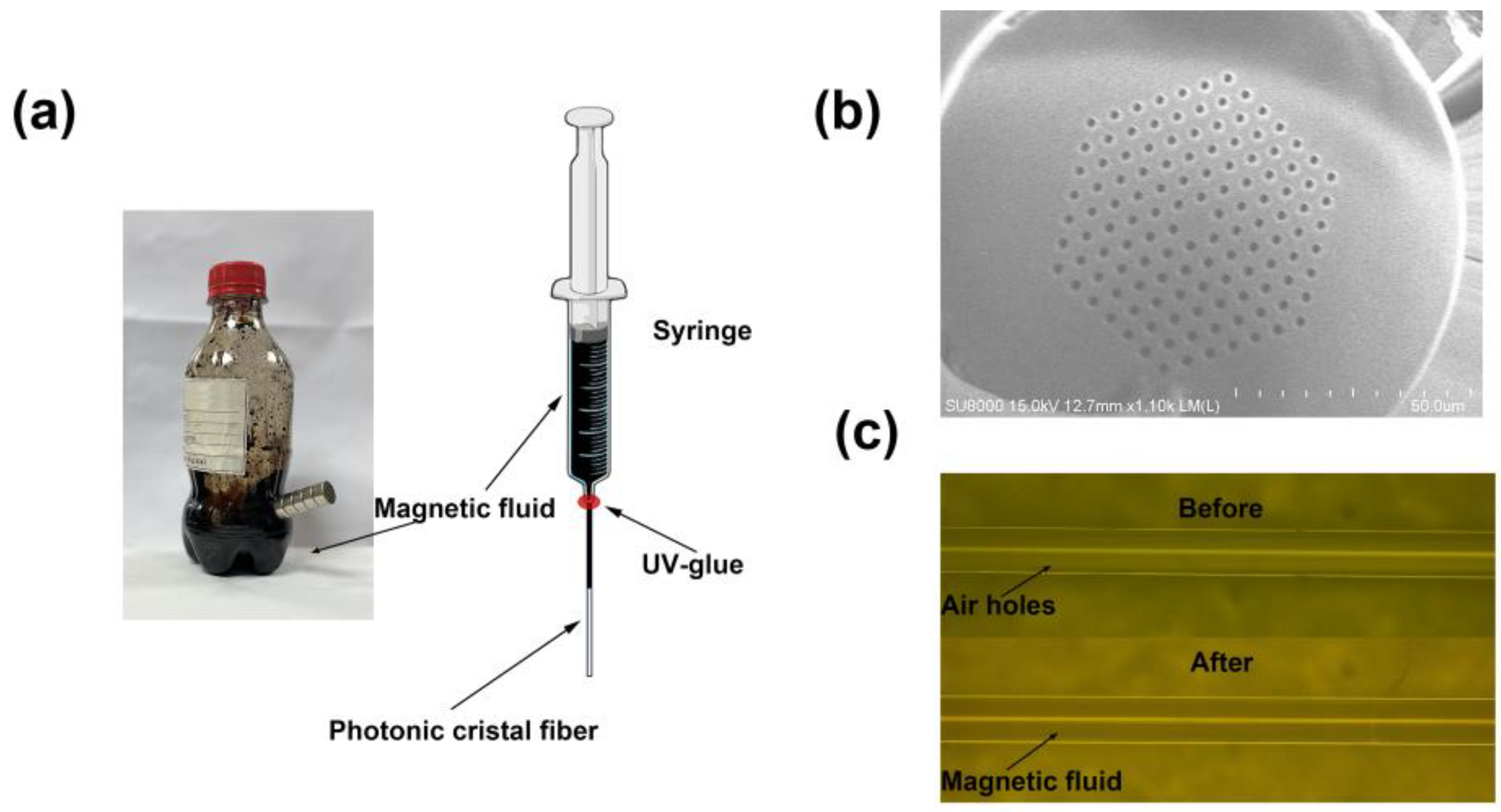
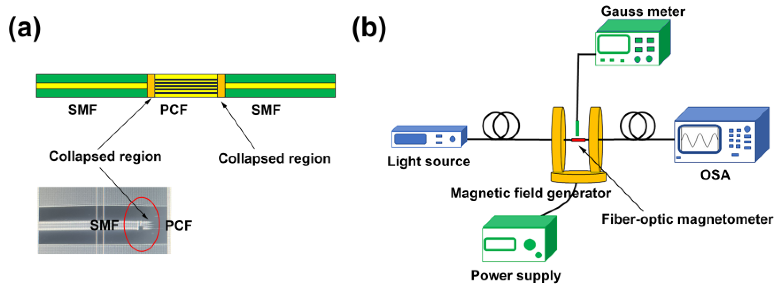
2. Materials and Methods
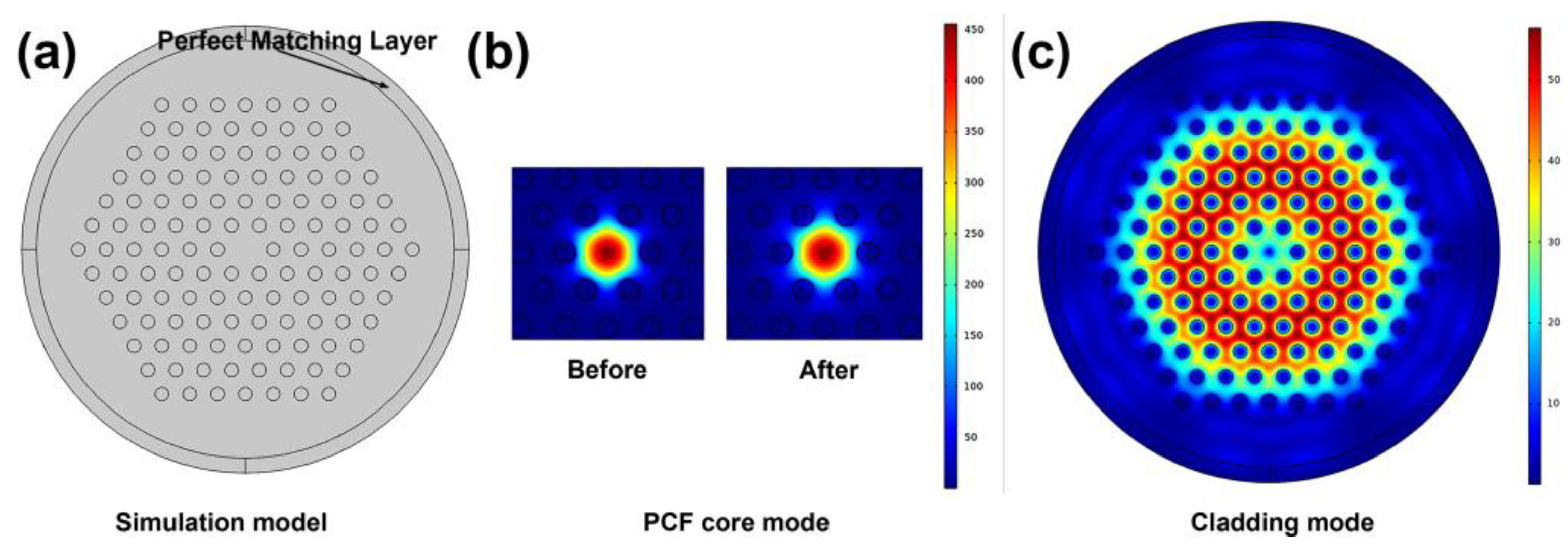
3. Results and Discussion
4. Conclusions
Author Contributions
Funding
Data Availability Statement
Conflicts of Interest
References
- Liu, C.; Shen, T.; Wu, H.B.; Feng, Y.; Chen, J.J. Applications of magneto-strictive, magneto-optical, magnetic fluid materials in optical fiber current sensors and optical fiber magnetic field sensors: A review. Opt. Fiber Technol. 2021, 65, 102634. [Google Scholar] [CrossRef]
- Li, X.; Yu, Q.; Zhou, X.; Zhang, Y.; Lv, R.; Zhao, Y. Magnetic sensing technology of fiber optic interferometer based on magnetic fluid: A review. Meas. J. Int. Meas. Confed. 2023, 216, 112929. [Google Scholar] [CrossRef]
- Alberto, N.; Domingues, M.F.; Marques, C.; André, P.; Antunes, P. Optical fiber magnetic field sensors based on magnetic fluid: A review. Sensors 2018, 18, 4325. [Google Scholar] [CrossRef] [PubMed]
- Liu, T.; Chen, X.; Di, Z.; Zhang, J.; Li, X.; Chen, J. Tunable magneto-optical wavelength filter of long-period fiber grating with magnetic fluids. Appl. Phys. Lett. 2007, 91, 3–6. [Google Scholar] [CrossRef]
- Horng, H.E.; Chen, C.S.; Fang, K.L.; Yang, S.Y.; Chieh, J.J.; Hong, C.Y.; Yang, H.C. Tunable optical switch using magnetic fluids. Appl. Phys. Lett. 2004, 85, 5592–5594. [Google Scholar] [CrossRef]
- Zhang, D.; Wei, H.; Hu, H.; Krishnaswamy, S. Highly sensitive magnetic field microsensor based on direct laser writing of fiber-tip optofluidic Fabry-Pérot cavity. APL Photonics 2020, 5, 076112. [Google Scholar] [CrossRef]
- Zhou, X.; Li, X.; Li, S.; An, G.W.; Cheng, T. Magnetic Field Sensing Based on SPR Optical Fiber Sensor Interacting with Magnetic Fluid. IEEE Trans. Instrum. Meas. 2019, 68, 234–239. [Google Scholar] [CrossRef]
- Huang, Y.; Qiu, H.; Deng, C.; Lian, Z.; Yang, Y.; Yu, Y.; Hu, C.; Dong, Y.; Shang, Y.; Zhang, X.; et al. Simultaneous measurement of magnetic field and temperature based on two anti-resonant modes in hollow core Bragg fiber. Opt. Express 2021, 29, 32208. [Google Scholar] [CrossRef]
- Yuan, M.; Pu, S.; Li, D.; Li, Y.; Hao, Z.; Zhang, Y.; Zhang, C.; Yan, S. Extremely high sensitivity magnetic field sensing based on birefringence-induced dispersion turning point characteristics of microfiber coupler. Results Phys. 2021, 29, 104743. [Google Scholar] [CrossRef]
- Chen, Y.; Hu, Y.; Cheng, H.; Yan, F.; Lin, Q.; Chen, Y.; Wu, P.; Chen, L.; Liu, G.; Peng, G.; et al. Side-Polished Single-Mode-Multimode-Single-Mode Fiber Structure for the Vector Magnetic Field Sensing. J. Light. Technol. 2020, 38, 5837–5843. [Google Scholar] [CrossRef]
- Lv, R.Q.; Qian, J.K.; Zhao, Y. Magnetic field sensor based on the magnetic-fluid-clad combined with singlemode-multimode-singlemode fiber and large core-offset splicing structure. Meas. Sci. Technol. 2018, 29, 035204. [Google Scholar] [CrossRef]
- Kendir, E.; Yaltkaya, Ş. Variations of magnetic field measurement with an extrinsic Fabry-Perot interferometer by double-beam technique. Meas. J. Int. Meas. Confed. 2020, 151, 25–27. [Google Scholar] [CrossRef]
- Dai, J.; Yang, M.; Li, X.; Liu, H.; Tong, X. Magnetic field sensor based on magnetic fluid clad etched fiber Bragg grating. Opt. Fiber Technol. 2011, 17, 210–213. [Google Scholar] [CrossRef]
- Li, B.; Zhang, F.; Yan, X.; Zhang, X.; Wang, F.; Cheng, T. An Optical Fiber-Based Surface Plasmon Resonance Sensor for Simultaneous Measurement of Temperature and Magnetic Field Intensity. IEEE Trans. Instrum. Meas. 2022, 71, 7000407. [Google Scholar] [CrossRef]
- Duan, S.; Liu, B.; Zhang, H.; Liu, H.; Lin, W.; Wu, J.; Song, B. Intensity-interrogated magnetic sensor based on S-tapered and multimode fiber integrated with ferrofluids. Appl. Opt. 2021, 60, 10743. [Google Scholar] [CrossRef] [PubMed]
- Lu, L.; Miao, Y.; Zhang, H.; Li, B.; Fei, C.; Zhang, K. Magnetic sensor based on serial-tilted-tapered optical fiber for weak-magnetic-field measurement. Appl. Opt. 2020, 59, 2791. [Google Scholar] [CrossRef] [PubMed]
- Tao, Y.; Li, T.; Feng, W. Reflective Fiber-Optic Magnetic Field Sensor Based on a Magnetic-Fluid-Filled Capillary Probe Structure. Meas. Sci. Technol. 2021, 32, 095117. [Google Scholar] [CrossRef]
- Chaudhary, V.S.; Kumar, D.; Kumar, S. SPR-Assisted Photonic Crystal Fiber-Based Dual-Wavelength Single Polarizing Filter with Improved Performance. IEEE Trans. Plasma Sci. 2021, 49, 3803–3810. [Google Scholar] [CrossRef]
- Huang, Y.; Wang, Y.; Zhang, L.; Shao, Y.; Zhang, F.; Liao, C.; Wang, Y. Tunable Electro-Optical Modulator Based on a Photonic Crystal Fiber Selectively Filled with Liquid Crystal. J. Light. Technol. 2019, 37, 1903–1908. [Google Scholar] [CrossRef]
- Ding, X.Z.; Yang, H.-Z.; Qiao, X.-G.; Zhang, P.; Tian, O.; Rong, Q.Z.; Nazal, N.A.M.; Lim, K.-S.; Ahmad, H. Mach–Zehnder interferometric magnetic field sensor based on a photonic crystal fiber and magnetic fluid. Appl. Opt. 2018, 57, 2050. [Google Scholar] [CrossRef]
- Zhang, Y.; Liu, N.; Zhang, N.; Gao, Q.; Li, X.; Yu, M.; Deng, Y.; Shi, X.; Li, M. The photonic crystal fiber filled with magnetic fluid for magnetic field sensing. In Proceedings of the Third International Conference on Machine Learning and Computer Application (ICMLCA 2022), Shenyang, China, 3–5 November 2023; p. 183. [Google Scholar] [CrossRef]
- Taghizadeh, M.; Bozorgzadeh, F.; Ghorbani, M. Designing magnetic field sensor based on tapered photonic crystal fibre assisted by a ferrofluid. Sci. Rep. 2021, 11, 14325. [Google Scholar] [CrossRef] [PubMed]
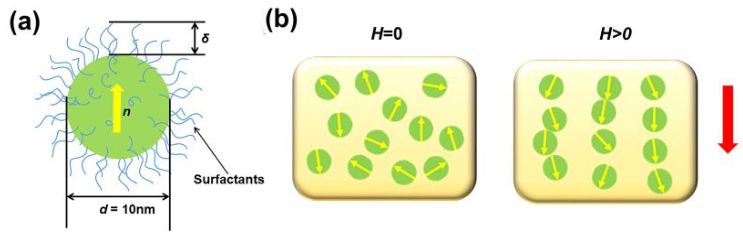
- Odenbach, S. Magnetic fluids—Suspensions of magnetic dipoles and their magnetic control. J. Phys. Condens. Matter 2003, 15, S1497. [Google Scholar] [CrossRef]
- Beig, R.; Wien, A.; Englert, B.-G.; Ismaning, G.; Frisch, U.; Nice, F.; Hänggi, P.; Augsburg, G.; Hepp, K.; Zürich, S.; et al. Ferrofluids—Magnetically Controllable Fluids and Their Applications; Springer: Berlin/Heidelberg, Germany, 2002; ISBN 3540439781. [Google Scholar]
- Wu, J.; Miao, Y.; Lin, W.; Song, B.; Zhang, K.; Zhang, H.; Liu, B.; Yao, J. Magnetic-field sensor based on core-offset tapered optical fiber and magnetic fluid. J. Opt. 2014, 16, 075705. [Google Scholar] [CrossRef]
- Wu, J.; Miao, Y.; Lin, W.; Zhang, K.; Song, B.; Zhang, H.; Liu, B.; Yao, J. Dual-direction magnetic field sensor based on core-offset microfiber and ferrofluid. IEEE Photonics Technol. Lett. 2014, 26, 1581–1584. [Google Scholar] [CrossRef]
- Wang, J.; Pei, L.; Wang, J.; Ruan, Z.; Zheng, J.; Li, J.; Ning, T. Magnetic field and temperature dual-parameter sensor based on magnetic fluid materials filled photonic crystal fiber. Opt. Express 2020, 28, 1456. [Google Scholar] [CrossRef]
- Ye, J. Optic fiber magnetic field sensor based on the miniature pull-taper twin-core photonic crystal fiber. In Proceedings of the 14th International Photonics and Optoelectronics Meetings (POEM 2022), Wuhan, China, 18–20 December 2022; p. 49. [Google Scholar] [CrossRef]


| Structure | Linear Region | Sensitivity | Photoelectric Conversion | Refs |
|---|---|---|---|---|
| SMF-PCF-SMF (2018) | 2–20 mT | 0.13 dB/mT (spectrum dip) | No | [20] |
| SMF-PCF-SMF (2020) | 0–10 mT | 0.92463 nm/mT (spectrum dip) | No | [27] |
| SMF-PCF-SMF (2020) | 0–140 mT | 0.021 dB/mT (spectrum dip) | No | [22] |
| SMF-PCF-SMF (2023) | 2–30 mT | 0.37dB/mT (spectrum dip) | No | [21] |
| SMF-PCF-Reflective end (2023) | 6–15 mT | 1.16 nm/mT (spectrum dip) | No | [28] |
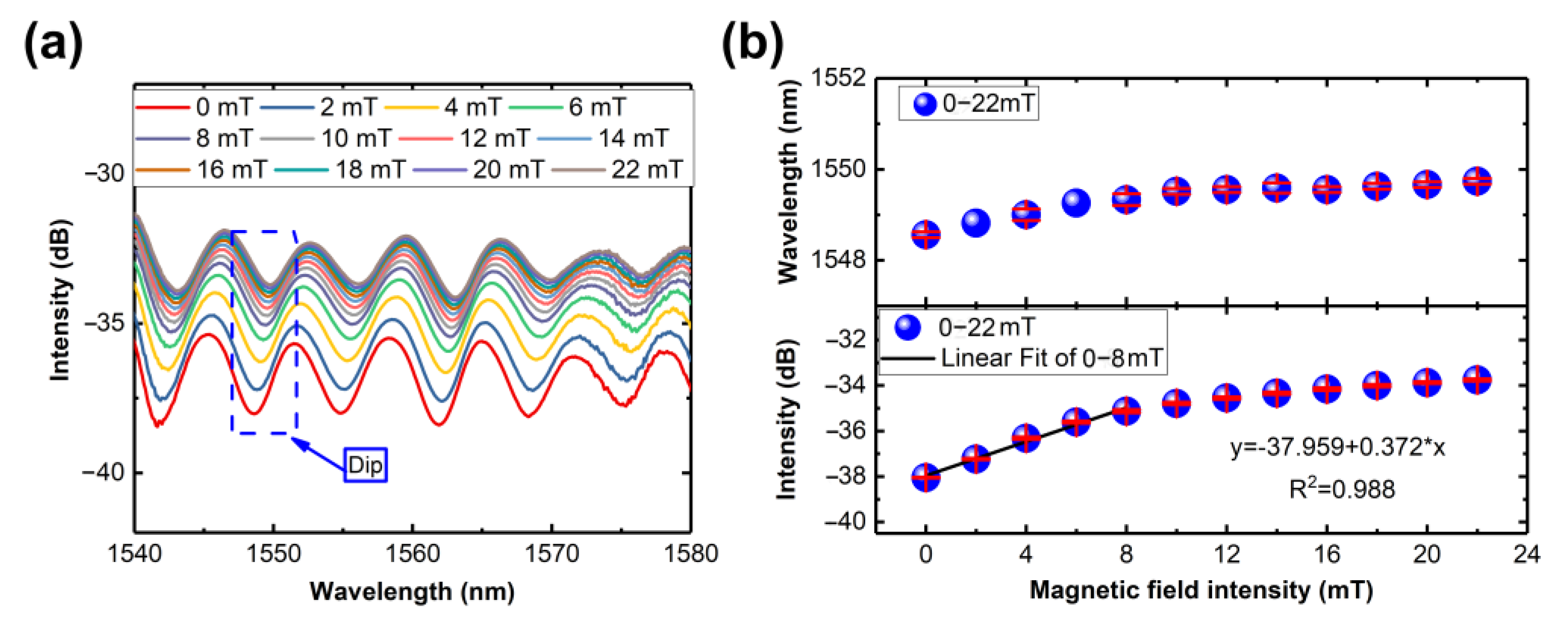
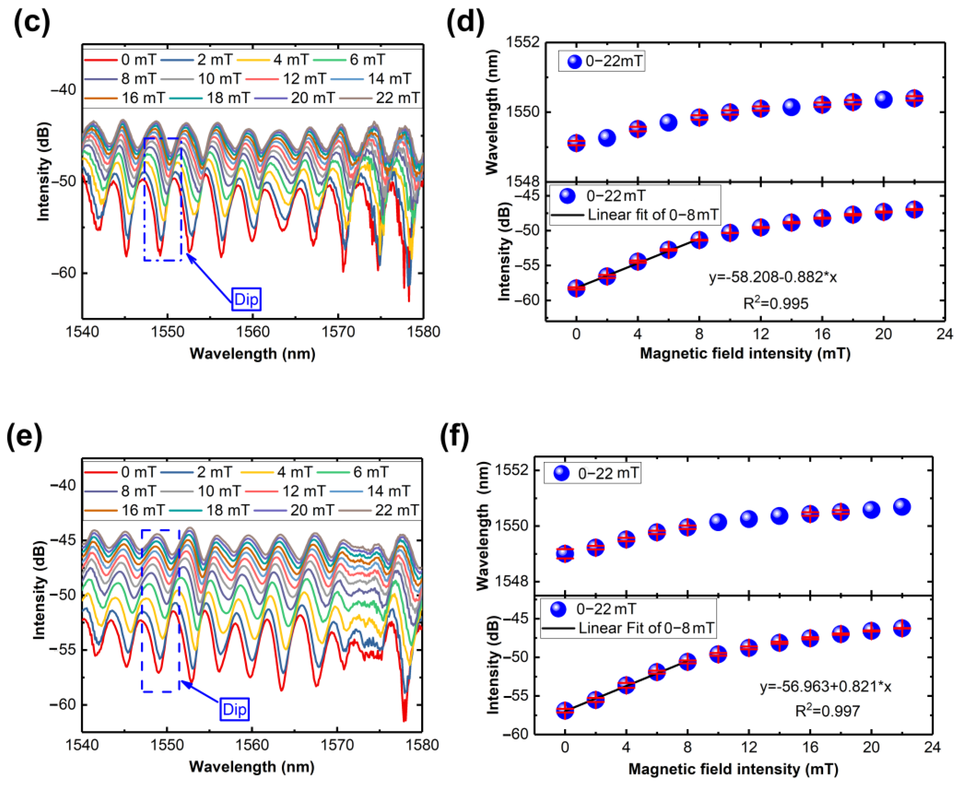
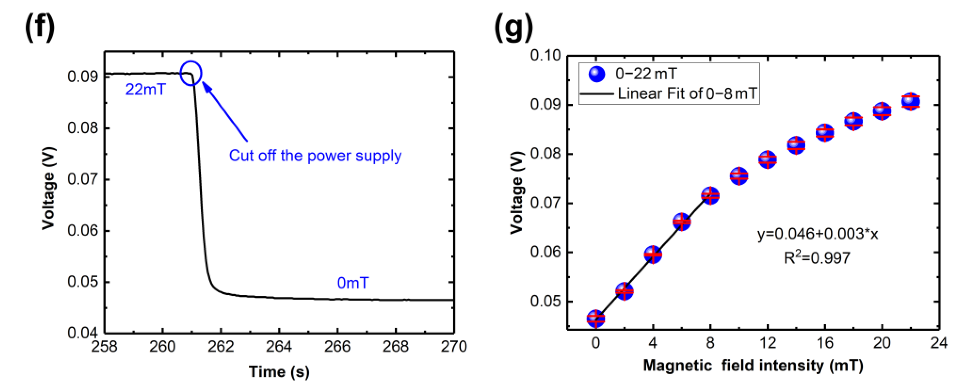
| Our structure | 0–8 mT | 0.238 dB/mT (1550.03 nm) | 0.003 V/mT | This work |
Disclaimer/Publisher’s Note: The statements, opinions and data contained in all publications are solely those of the individual author(s) and contributor(s) and not of MDPI and/or the editor(s). MDPI and/or the editor(s) disclaim responsibility for any injury to people or property resulting from any ideas, methods, instructions or products referred to in the content. |
© 2024 by the authors. Licensee MDPI, Basel, Switzerland. This article is an open access article distributed under the terms and conditions of the Creative Commons Attribution (CC BY) license (https://creativecommons.org/licenses/by/4.0/).
Share and Cite
Zhu, L.; Wang, H.; Lin, Q.; Yao, K.; Xian, D.; Yang, P.; Zhao, N.; Tian, B.; Jiang, Z. An Intensity-Demodulated Fiber-Optic Magnetometer Based on Nanostructured Magnetic Fluid-Filled Fluidic Photonic Crystal Fibers. Nanomaterials 2024, 14, 221. https://doi.org/10.3390/nano14020221
Zhu L, Wang H, Lin Q, Yao K, Xian D, Yang P, Zhao N, Tian B, Jiang Z. An Intensity-Demodulated Fiber-Optic Magnetometer Based on Nanostructured Magnetic Fluid-Filled Fluidic Photonic Crystal Fibers. Nanomaterials. 2024; 14(2):221. https://doi.org/10.3390/nano14020221
Chicago/Turabian StyleZhu, Liangquan, Huan Wang, Qijing Lin, Kun Yao, Dan Xian, Ping Yang, Na Zhao, Bian Tian, and Zhuangde Jiang. 2024. "An Intensity-Demodulated Fiber-Optic Magnetometer Based on Nanostructured Magnetic Fluid-Filled Fluidic Photonic Crystal Fibers" Nanomaterials 14, no. 2: 221. https://doi.org/10.3390/nano14020221
APA StyleZhu, L., Wang, H., Lin, Q., Yao, K., Xian, D., Yang, P., Zhao, N., Tian, B., & Jiang, Z. (2024). An Intensity-Demodulated Fiber-Optic Magnetometer Based on Nanostructured Magnetic Fluid-Filled Fluidic Photonic Crystal Fibers. Nanomaterials, 14(2), 221. https://doi.org/10.3390/nano14020221