
Phase Separation Prevents the Synthesis of VBi2Te4 by Molecular Beam Epitaxy

Abstract
:1. Introduction
2. Materials and Methods
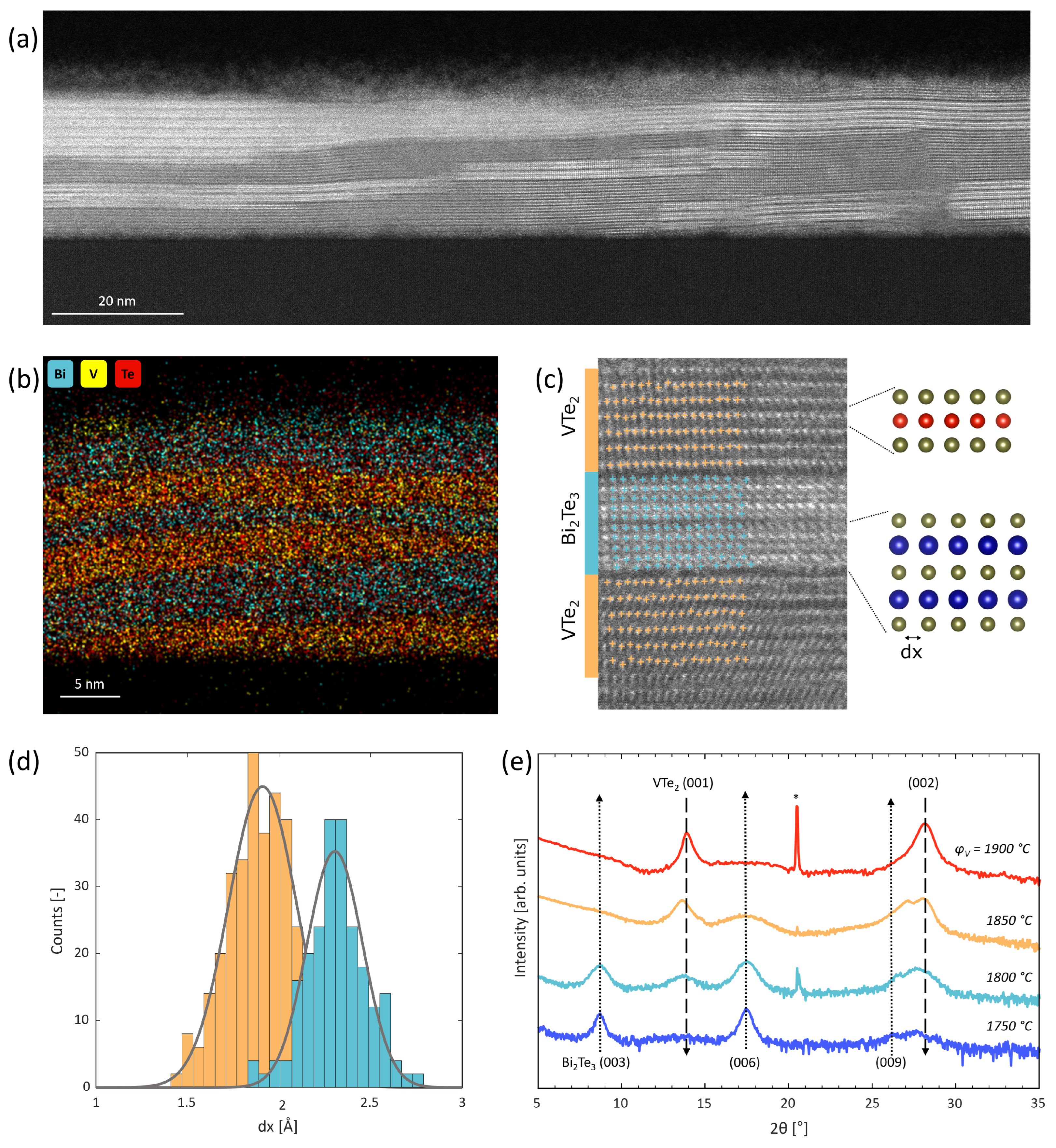
3. Results
4. Discussion

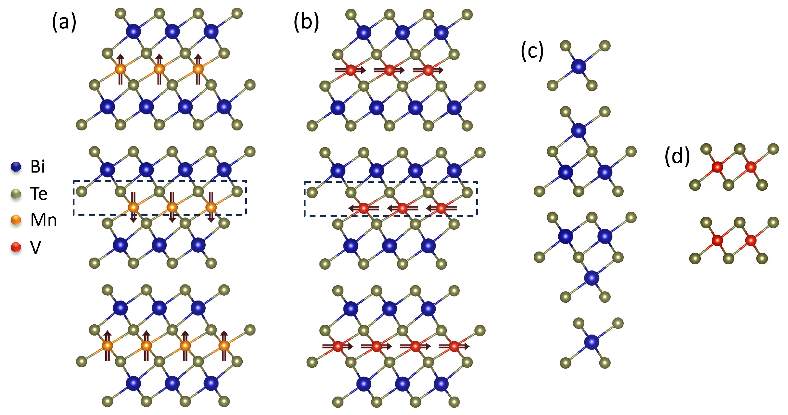
| Material | Experimentally Observed? | a [Å] | Intercalated Layer | a [Å] | Lattice Structure | [Å] |
|---|---|---|---|---|---|---|
| VBi2Te4 | No | 4.34–4.37 [9,26,33,34,35] | VTe2 | 3.59 | Hexagonal, P1 | 0.75–0.78 |
| MnBi2Te4 | Yes [8,21,22,23,27,36] | 4.33 [36] | MnTe | 4.13 [37] | Hexagonal, P63/mmc | 0.20 |
| FeBi2Te4 | Yes [38] | 4.39 [9,38] | FeTe | 3.83 [38,39] | Tetragonal, P4/nmm | 0.56 |
| FeTe2 | 3.77 [40] | Hexagonal, P1 | 0.63 | |||
| EuBi2Te4 | No | 4.50 [9,33] | EuTe | 6.60 [41,42] | Cubic, Fm | 2.10 |
| EuTe2 | 6.97 [43] | Tetragonal, I4/mcm | 2.47 | |||
| NiBi2Te4 | Yes * | 4.30 [9,33] | NiTe2 | 3.86 [44] | Hexagonal, P1 | 0.44 |
| CrBi2Te4 | No | 4.32 [45] | CrTe2 | 3.79 [46] | Hexagonal, P1 | 0.53 |
| TiBi2Te4 | No | 4.39 [9] | TiTe2 | 3.78 [47] | Hexagonal, P1 | 0.61 |
| PbBi2Te4 | Yes [48,49] | 4.44 [49] | PbTe | 6.46 [50] | Cubic, Fm | 2.02 |
| SnBi2Te4 | Yes [51,52,53] | 4.40 [51,53] | SnTe | 6.32 [50] | Cubic, Fm | 1.92 |
| GeBi2Te4 | Yes [54,55] | 4.33 [54,55] | GeTe | 4.16 [50,56] | Rhombohedral, R | 0.17 |
Author Contributions
Funding
Data Availability Statement
Acknowledgments
Conflicts of Interest
References
- Hasan, M.Z.; Kane, C.L. Colloquium: Topological insulators. Rev. Mod. Phys. 2010, 82, 3045–3067. [Google Scholar] [CrossRef]
- Yu, R.; Zhang, W.; Zhang, H.J.; Zhang, S.C.; Dai, X.; Fang, Z. Quantized anomalous Hall effect in magnetic topological insulators. Science 2010, 329, 61–64. [Google Scholar] [CrossRef]
- Liu, C.X.; Qi, X.L.; Dai, X.; Fang, Z.; Zhang, S.C. Quantum anomalous Hall effect in Hg1−yMnyTe quantum wells. Phys. Rev. Lett. 2008, 101, 146802. [Google Scholar] [CrossRef] [PubMed]
- Liu, Q.; Liu, C.X.; Xu, C.; Qi, X.L.; Zhang, S.C. Magnetic impurities on the surface of a topological insulator. Phys. Rev. Lett. 2009, 102, 156603. [Google Scholar] [CrossRef] [PubMed]
- Haldane, F.D.M. Model for a quantum Hall effect without Landau levels: Condensed-matter realization of the “parity anomaly”. Phys. Rev. Lett. 1988, 61, 2015–2018. [Google Scholar] [CrossRef] [PubMed]
- Chang, C.Z.; Zhang, J.; Feng, X.; Shen, J.; Zhang, Z.; Guo, M.; Ou, Y.; Wei, P.; Jun, L.; Ji, Z.; et al. Experimental observation of the quantum anomalous Hall effect in a magnetic topological insulator. Science 2013, 340, 167–170. [Google Scholar] [CrossRef] [PubMed]
- Chang, C.Z.; Zhao, W.; Kim, D.Y.; Zhang, H.; Assaf, B.A.; Heiman, D.; Zhang, S.C.; Liu, C.; Chan, M.H.W.; Moodera, J.S. High-precision realization of robust quantum anomalous Hall state in a hard ferromagnetic topological insulator. Nat. Mater. 2015, 14, 473–477. [Google Scholar] [CrossRef] [PubMed]
- Deng, Y.; Yu, Y.; Shi, M.Z.; Guo, Z.; Xu, Z.; Wang, J.; Chen, X.H.; Zhang, Y. Quantum anomalous Hall effect in intrinsic magnetic topological insulator MnBi2Te4. Science 2020, 367, 895–900. [Google Scholar] [CrossRef]
- Li, J.; Li, Y.; Du, S.; Wang, Z.; Gu, B.L.; Zhang, S.C.; He, K.; Duan, W.; Xu, Y. Intrinsic magnetic topological insulators in van der Waals layered MnBi2Te4-family materials. Sci. Adv. 2019, 5, eaaw5685. [Google Scholar] [CrossRef]
- Watanabe, R.; Yoshimi, R.; Kawamura, M.; Mogi, M.; Tsukazaki, A.; Yu, X.Z.; Nakajima, K.; Takahashi, K.S.; Kawasaki, M.; Tokura, Y. Quantum anomalous Hall effect driven by magnetic proximity coupling in all-telluride based heterostructure. Appl. Phys. Lett. 2019, 115, 102403. [Google Scholar] [CrossRef]
- Ou, Y.; Liu, C.; Jiang, G.; Feng, Y.; Zhao, D.; Wu, W.; Wang, X.X.; Li, W.; Song, C.; Wang, L.L.; et al. Enhancing the quantum anomalous Hall effect by magnetic codoping in a topological insulator. Adv. Mater. 2018, 30, 1703062. [Google Scholar] [CrossRef]
- Qi, X.L.; Hughes, T.L.; Zhang, S.C. Topological field theory of time-reversal invariant insulators. Phys. Rev. B 2008, 78, 195424. [Google Scholar] [CrossRef]
- Li, R.; Wang, J.; Qi, X.L.; Zhang, S.C. Dynamical axion field in topological magnetic insulators. Nat. Phys. 2010, 6, 284–288. [Google Scholar] [CrossRef]
- Wang, P.; Ge, J.; Li, J.; Liu, Y.; Xu, Y.; Wang, J. Intrinsic magnetic topological insulators. Innovation 2021, 2, 100098. [Google Scholar] [CrossRef] [PubMed]
- Mogi, M.; Kawamura, M.; Yoshimi, R.; Tsukazaki, A.; Kozuka, Y.; Shirakawa, N.; Takahashi, K.S.; Kawasaki, M.; Tokura, Y. A magnetic heterostructure of topological insulators as a candidate for an axion insulator. Nat. Mater. 2017, 16, 516–521. [Google Scholar] [CrossRef] [PubMed]
- Grutter, A.J.; He, Q.L. Magnetic proximity effects in topological insulator heterostructures: Implementation and characterization. Phys. Rev. Mater. 2021, 5, 090301. [Google Scholar] [CrossRef]
- Hor, Y.S.; Roushan, P.; Beidenkopf, H.; Seo, J.; Qu, D.; Checkelsky, J.G.; Wray, L.A.; Hsieh, D.; Xia, Y.; Xu, S.Y.; et al. Development of ferromagnetism in the doped topological insulator Bi2−xMnxTe3. Phys. Rev. B 2010, 81, 195203. [Google Scholar] [CrossRef]
- Katmis, F.; Lauter, V.; Nogueira, F.S.; Assaf, B.A.; Jamer, M.E.; Wei, P.; Satpati, B.; Freeland, J.W.; Eremin, I.; Heiman, D.; et al. A high-temperature ferromagnetic topological insulating phase by proximity coupling. Nature 2016, 533, 513–516. [Google Scholar] [CrossRef] [PubMed]
- Tang, C.; Chang, C.Z.; Zhao, G.; Liu, Y.; Jiang, Z.; Liu, C.X.; McCartney, M.R.; Smith, D.J.; Chen, T.; Moodera, J.S.; et al. Above 400-K robust perpendicular ferromagnetic phase in a topological insulator. Sci. Adv. 2017, 3, e1700307. [Google Scholar] [CrossRef]
- He, Q.L.; Yin, G.; Yu, L.; Grutter, A.J.; Pan, L.; Chen, C.Z.; Che, X.; Yu, G.; Zhang, B.; Shao, Q.; et al. Topological transitions induced by antiferromagnetism in a thin-film topological insulator. Phys. Rev. Lett. 2018, 121, 096802. [Google Scholar] [CrossRef]
- Rienks, E.D.L.; Wimmer, S.; Sánchez-Barriga, J.; Caha, O.; Mandal, P.S.; Růžička, J.; Ney, A.; Steiner, H.; Volobuev, V.V.; Groiss, H.; et al. Large magnetic gap at the Dirac point in Bi2Te3/MnBi2Te4 heterostructures. Nature 2019, 576, 423–428. [Google Scholar] [CrossRef] [PubMed]
- Liu, C.; Wang, Y.; Li, H.; Wu, Y.; Li, Y.; Li, J.; He, K.; Xu, Y.; Zhang, J.; Wang, Y. Robust axion insulator and Chern insulator phases in a two-dimensional antiferromagnetic topological insulator. Nat. Mater. 2020, 19, 522–527. [Google Scholar] [CrossRef] [PubMed]
- Otrokov, M.M.; Klimovskikh, I.I.; Bentmann, H.; Estyunin, D.; Zeugner, A.; Aliev, Z.S.; Gaß, S.; Wolter, A.U.B.; Koroleva, A.V.; Shikin, A.M.; et al. Prediction and observation of an antiferromagnetic topological insulator. Nature 2019, 576, 416–422. [Google Scholar] [CrossRef]
- Otrokov, M.M.; Rusinov, I.P.; Blanco-Rey, M.; Hoffmann, M.; Vyazovskaya, A.Y.; Eremeev, S.V.; Ernst, A.; Echenique, P.M.; Arnau, A.; Chulkov, E.V. Unique thickness-dependent properties of the van der Waals interlayer antiferromagnet MnBi2Te4 films. Phys. Rev. Lett. 2019, 122, 107202. [Google Scholar] [CrossRef] [PubMed]
- Zhang, D.; Shi, M.; Zhu, T.; Xing, D.; Zhang, H.; Wang, J. Topological axion states in the magnetic insulator MnBi2Te4 with the quantized magnetoelectric effect. Phys. Rev. Lett. 2019, 122, 206401. [Google Scholar] [CrossRef]
- Petrov, E.K.; Men’shov, V.N.; Rusinov, I.P.; Hoffmann, M.; Ernst, A.; Otrokov, M.M.; Dugaev, V.K.; Menshchikova, T.V.; Chulkov, E.V. Domain wall induced spin-polarized flat bands in antiferromagnetic topological insulators. Phys. Rev. B 2021, 103, 235142. [Google Scholar] [CrossRef]
- Gong, Y.; Guo, J.; Li, J.; Zhu, K.; Liao, M.; Liu, X.; Zhang, Q.; Gu, L.; Tang, L.; Feng, X.; et al. Experimental realization of an intrinsic magnetic topological insulator. Chin. Phys. Lett. 2019, 36, 076801. [Google Scholar] [CrossRef]
- Jiao, F.; Wang, J.; Wang, X.; Tian, Q.; Chang, M.; Cai, L.; Zhu, S.; Zhang, D.; Lu, Q.; Wang, C.; et al. The Layer-Inserting Growth of Antiferromagnetic Topological Insulator MnBi2Te4 Based on Symmetry and Its X-ray Photoelectron Spectroscopy. J. Supercond. Nov. Magn. 2021, 34, 1485–1493. [Google Scholar] [CrossRef]
- Sans, J.A.; Vilaplana, R.; da Silva, E.L.; Popescu, C.; Cuenca-Gotor, V.P.; Andrada-Chacón, A.; Sánchez-Benitez, J.; Gomis, O.; Pereira, A.L.J.; Rodríguez-Hernández, P.; et al. Characterization and Decomposition of the Natural van der Waals SnSb2Te4 under Compression. Inorg. Chem. 2020, 59, 9900–9918. [Google Scholar] [CrossRef]
- Zeugner, A.; Nietschke, F.; Wolter, A.U.B.; Gaß, S.; Vidal, R.C.; Peixoto, T.R.F.; Pohl, D.; Damm, C.; Lubk, A.; Hentrich, R.; et al. Chemical Aspects of the Candidate Antiferromagnetic Topological Insulator MnBi2Te4. Chem. Mater. 2019, 31, 2795–2806. [Google Scholar] [CrossRef]
- Parker, D.S.; Yin, L.; Samolyuk, G.D.; Sanjeewa, L.D.; Wang, X.; Cooper, V.R.; Liu, Y.; Bud’ko, S.; Sefat, A.S. Insulating antiferromagnetism in VTe. Phys. Rev. B 2022, 105, 174414. [Google Scholar] [CrossRef]
- Zhang, J.M.; Ming, W.; Huang, Z.; Liu, G.B.; Kou, X.; Fan, Y.; Wang, K.L.; Yao, Y. Stability, electronic, and magnetic properties of the magnetically doped topological insulators Bi2Se3, Bi2Te3, and Sb2Te3. Phys. Rev. B 2013, 88, 235131. [Google Scholar] [CrossRef]
- Li, Z.; Li, J.; He, K.; Wan, X.; Duan, W.; Xu, Y. Tunable interlayer magnetism and band topology in van der Waals heterostructures of MnBi2Te4-family materials. Phys. Rev. B 2020, 102, 081107. [Google Scholar] [CrossRef]
- Zhang, Y.; Wang, Y.; Yang, W.; Zhang, H.; Jia, J. Strain-tunable magnetism and topological states in layered VBi2Te4. Phys. Chem. Chem. Phys. 2023, 25, 28189–28195. [Google Scholar] [CrossRef] [PubMed]
- Zhu, W.; Song, C.; Liao, L.; Zhou, Z.; Bai, H.; Zhou, Y.; Pan, F. Quantum anomalous Hall insulator state in ferromagnetically ordered MnBi2Te4/VBi2Te4 heterostructures. Phys. Rev. B 2020, 102, 085111. [Google Scholar] [CrossRef]
- Lee, D.S.; Kim, T.H.; Park, C.H.; Chung, C.Y.; Lim, Y.S.; Seo, W.S.; Park, H.H. Crystal structure, properties and nanostructuring of a new layered chalcogenide semiconductor, Bi2MnTe4. CrystEngComm 2013, 15, 5532–5538. [Google Scholar] [CrossRef]
- Kriegner, D.; Reichlova, H.; Grenzer, J.; Schmidt, W.; Ressouche, E.; Godinho, J.; Wagner, T.; Martin, S.Y.; Shick, A.B.; Volobuev, V.V.; et al. Magnetic anisotropy in antiferromagnetic hexagonal MnTe. Phys. Rev. B 2017, 96, 214418. [Google Scholar] [CrossRef]
- Saxena, A.; Rani, P.; Nagpal, V.; Patnaik, S.; Felner, I.; Awana, V.P.S. Crystal growth and characterization of possible new magnetic topological insulators FeBi2Te4. J. Supercond. Nov. Magn. 2020, 33, 2251–2256. [Google Scholar] [CrossRef]
- Oyler, K.D.; Ke, X.; Sines, I.T.; Schiffer, P.; Schaak, R.E. Chemical Synthesis of Two-Dimensional Iron Chalcogenide Nanosheets: FeSe, FeTe, Fe(Se,Te), and FeTe2. Chem. Mater. 2009, 21, 3655–3661. [Google Scholar] [CrossRef]
- Wu, H.; Feng, Z.; Pal, A.; Dong, H.; Jing, C.; Wang, K.; Zhang, S.; Deng, W.; Li, S.; Feng, J.; et al. Evolution of Temperature-Induced Isostructural Phase Transition in a Newly Grown Layered FeTe2 Single Crystal. Chem. Mater. 2021, 33, 4927–4935. [Google Scholar] [CrossRef]
- Radomska, A.; Balcerzak, T. Calculations of EuTe magnetic phase diagram for external pressure. Acta Phys. Pol. A 2000, 98, 83–91. [Google Scholar] [CrossRef]
- Fornari, C.I.; Bentmann, H.; Morelhão, S.L.; Peixoto, T.R.F.; Rappl, P.H.O.; Tcakaev, A.V.; Zabolotnyy, V.; Kamp, M.; Lee, T.L.; Min, C.H.; et al. Incorporation of Europium in Bi2Te3 topological insulator epitaxial films. J. Phys. Chem. C 2020, 124, 16048–16057. [Google Scholar] [CrossRef]
- Yin, J.; Wu, C.; Li, L.; Yu, J.; Sun, H.; Shen, B.; Frandsen, B.A.; Yao, D.X.; Wang, M. Large negative magnetoresistance in the antiferromagnetic rare-earth dichalcogenide EuTe2. Phys. Rev. Mater. 2020, 4, 013405. [Google Scholar] [CrossRef]
- Xu, C.; Li, B.; Jiao, W.; Zhou, W.; Qian, B.; Sankar, R.; Zhigadlo, N.D.; Qi, Y.; Qian, D.; Chou, F.C.; et al. Topological type-II Dirac fermions approaching the Fermi level in a transition metal dichalcogenide NiTe2. Chem. Mater. 2018, 30, 4823–4830. [Google Scholar] [CrossRef]
- Petrov, E.K.; Ernst, A.; Menshchikova, T.V.; Chulkov, E.V. Intrinsic magnetic topological insulator state induced by the Jahn–Teller effect. J. Phys. Chem. Lett. 2021, 12, 9076–9085. [Google Scholar] [CrossRef] [PubMed]
- Freitas, D.C.; Weht, R.; Sulpice, A.; Remenyi, G.; Strobel, P.; Gay, F.; Marcus, J.; Núñez-Regueiro, M. Ferromagnetism in layered metastable 1T-CrTe2. J. Phys. Condens. Matter 2015, 27, 176002. [Google Scholar] [CrossRef] [PubMed]
- Chen, P.; Pai, W.W.; Chan, Y.H.; Takayama, A.; Xu, C.Z.; Karn, A.; Hasegawa, S.; Chou, M.Y.; Mo, S.K.; Fedorov, A.V.; et al. Emergence of charge density waves and a pseudogap in single-layer TiTe2. Nat. Commun. 2017, 8, 516. [Google Scholar] [CrossRef]
- Kuroda, K.; Miyahara, H.; Ye, M.; Eremeev, S.V.; Koroteev, Y.M.; Krasovskii, E.E.; Chulkov, E.V.; Hiramoto, S.; Moriyoshi, C.; Kuroiwa, Y.; et al. Experimental verification of PbBi2Te4 as a 3D topological insulator. Phys. Rev. Lett. 2012, 108, 206803. [Google Scholar] [CrossRef]
- Xu, X.; Ni, D.; Xie, W.; Cava, R.J. Superconductivity in electron-doped PbBi2Te4. Phys. Rev. B 2023, 108, 054525. [Google Scholar] [CrossRef]
- Bauer Pereira, P.; Sergueev, I.; Gorsse, S.; Dadda, J.; Müller, E.; Hermann, R.P. Lattice dynamics and structure of GeTe, SnTe and PbTe. Phys. Status Solidi (B) 2013, 250, 1300–1307. [Google Scholar] [CrossRef]
- Saxena, A.; Karn, N.K.; Sharma, M.M.; Awana, V.P.S. Detailed structural and topological analysis of SnBi2Te4 single crystal. J. Phys. Chem. Solids 2023, 174, 111169. [Google Scholar] [CrossRef]
- Zou, Y.C.; Chen, Z.G.; Zhang, E.; Kong, F.; Lu, Y.; Wang, L.; Drennan, J.; Wang, Z.; Xiu, F.; Cho, K.; et al. Atomic disorders in layer structured topological insulator SnBi2Te4 nanoplates. Nano Res. 2018, 11, 696–706. [Google Scholar] [CrossRef]
- Vilaplana, R.; Sans, J.A.; Manjón, F.J.; Andrada-Chacón, A.; Sánchez-Benítez, J.; Popescu, C.; Gomis, O.; Pereira, A.L.J.; García-Domene, B.; Rodríguez-Hernández, P.; et al. Structural and electrical study of the topological insulator SnBi2Te4 at high pressure. J. Alloys Compd. 2016, 685, 962–970. [Google Scholar] [CrossRef]
- Marcinkova, A.; Wang, J.K.; Slavonic, C.; Nevidomskyy, A.H.; Kelly, K.F.; Filinchuk, Y.; Morosan, E. Topological metal behavior in GeBi2Te4 single crystals. Phys. Rev. B 2013, 88, 165128. [Google Scholar] [CrossRef]
- Frolov, A.S.; Usachov, D.Y.; Tarasov, A.V.; Fedorov, A.V.; Bokai, K.A.; Klimovskikh, I.; Stolyarov, V.S.; Sergeev, A.I.; Lavrov, A.N.; Golyashov, V.A.; et al. Magnetic Dirac semimetal state of (Mn,Ge)Bi2Te4. arXiv 2023, arXiv:2306.13024. [Google Scholar]
- Serrano-Sánchez, F.; Funes, M.; Nemes, N.M.; Dura, O.J.; Martínez, J.L.; Prado-Gonjal, J.; Fernández-Díaz, M.T.; Alonso, J.A. Low lattice thermal conductivity in arc-melted GeTe with Ge-deficient crystal structure. Appl. Phys. Lett. 2018, 113, 083902. [Google Scholar] [CrossRef]
- Bhattacharjee, N.; Mahalingam, K.; Fedorko, A.; Lauter, V.; Matzelle, M.; Singh, B.; Grutter, A.; Will-Cole, A.; Page, M.; McConney, M.; et al. Topological antiferromagnetic Van der Waals phase in topological insulator/ferromagnet heterostructures synthesized by a CMOS-compatible sputtering technique. Adv. Mater. 2022, 34, 2108790. [Google Scholar] [CrossRef] [PubMed]

Disclaimer/Publisher’s Note: The statements, opinions and data contained in all publications are solely those of the individual author(s) and contributor(s) and not of MDPI and/or the editor(s). MDPI and/or the editor(s) disclaim responsibility for any injury to people or property resulting from any ideas, methods, instructions or products referred to in the content. |
© 2023 by the authors. Licensee MDPI, Basel, Switzerland. This article is an open access article distributed under the terms and conditions of the Creative Commons Attribution (CC BY) license (https://creativecommons.org/licenses/by/4.0/).
Share and Cite
Altena, M.; Jansen, T.; Tsvetanova, M.; Brinkman, A. Phase Separation Prevents the Synthesis of VBi2Te4 by Molecular Beam Epitaxy. Nanomaterials 2024, 14, 87. https://doi.org/10.3390/nano14010087
Altena M, Jansen T, Tsvetanova M, Brinkman A. Phase Separation Prevents the Synthesis of VBi2Te4 by Molecular Beam Epitaxy. Nanomaterials. 2024; 14(1):87. https://doi.org/10.3390/nano14010087
Chicago/Turabian StyleAltena, Marieke, Thies Jansen, Martina Tsvetanova, and Alexander Brinkman. 2024. "Phase Separation Prevents the Synthesis of VBi2Te4 by Molecular Beam Epitaxy" Nanomaterials 14, no. 1: 87. https://doi.org/10.3390/nano14010087
APA StyleAltena, M., Jansen, T., Tsvetanova, M., & Brinkman, A. (2024). Phase Separation Prevents the Synthesis of VBi2Te4 by Molecular Beam Epitaxy. Nanomaterials, 14(1), 87. https://doi.org/10.3390/nano14010087