Abstract
Studies about adding graphene reinforcement to improve the microfabrication performance of alumina (Al2O3) ceramic materials are still too rare and incomplete to satisfy sustainable manufacturing requirements. Therefore, this study aims to develop a detailed understanding of the effect of graphene reinforcement to enhance the laser micromachining performance of Al2O3-based nanocomposites. To achieve this, high-density Al2O3 nanocomposite specimens were fabricated with 0 wt.%, 0.5 wt.%, 1 wt.%, 1.5 wt.%, and 2.5 wt.% graphene nanoplatelets (GNPs) using a high-frequency induction heating process. The specimens were subjected to laser micromachining. Afterward, the effects of the GNP contents on the ablation depth/width, surface morphology, surface roughness, and material removal rate were studied. The results indicate that the micro-fabrication performance of the nanocomposites was significantly affected by the GNP content. All nanocomposites exhibited improvement in the ablation depth and material removal rate compared to the base Al2O3 (0 wt.% GNP). For instance, at a higher scanning speed, the ablation depth was increased by a factor of 10 times for the GNP-reinforced specimens compared to the base Al2O3 nanocomposites. In addition, the MRRs were increased by 2134%, 2391%, 2915%, and 2427% for the 0.5 wt.%, 1 wt.%, 1.5 wt.%, and 2.5 wt.% GNP/Al2O3 nanocomposites, respectively, compared to the base Al2O3 specimens. Likewise, the surface roughness and surface morphology were considerably improved for all GNP/Al2O3 nanocomposite specimens compared to the base Al2O3. This is because the GNP reinforcement reduced the ablation threshold and increased the material removal efficiency by increasing the optical absorbance and thermal conductivity and reducing the grain size of the Al2O3 nanocomposites. Among the GNP/Al2O3 nanocomposites, the 0.5 wt.% and 1 wt.% GNP specimens showed superior performance with minimum defects in most laser micromachining conditions. Overall, the results show that the GNP-reinforced Al2O3 nanocomposites can be machined with high quality and a high production rate using a basic fiber laser system (20 Watts) with very low power consumption. This study shows huge potential for adding graphene to alumina ceramic-based materials to improve their machinability.
1. Introduction
Ceramics have attractive properties such as high elastic stiffness, mechanical strength, biocompatibility, and stability at high temperatures, making them useful for biomedical, electronic, automotive, and aerospace applications [1]. Alumina is an example of a ceramic material that is very commonly used in a wide range of applications, such as micro-reactors [2], microfluidic devices [3], heat exchangers, heatsinks [4], and electronic substrates [3]. However, these materials have been limited by their intrinsic brittleness, high hardness, poor electrical and thermal conductivity, and poor machinability. To overcome these challenges, alumina ceramic matrix composites reinforced with nanostructure reinforcement have been developed to create new advanced materials with unique properties that cannot be obtained using a single monolithic ceramic. Earlier attempts to fabricate ceramic matrix composites have reinforced them with ceramic or metallic particles, fibers, or whiskers [5,6,7]. However, incorporating alumina ceramics with these reinforcement materials cannot satisfy the requirements of their direct use as a structural component, such as in armor [8,9,10] or dental implants [11]. With the emergence of graphene, it has become the ideal nanostructure filler for improving the toughness, brittleness, and electrical and thermal conductivity of metal/ceramic-based nanocomposites [12,13,14,15]. This is because graphene inhibits grain growth, and the network distribution of graphene reinforcement enhances ceramic conductivity [11,16].
In the recently published literature on using graphene for reinforcing ceramic-based nanocomposites, Al2O3 matrix nanocomposites have been of particular interest since they have exhibited improvements in mechanical properties and thermal and electrical conductivity compared to pure ceramic matrices [17,18,19,20,21,22]. For instance, He et al. [23] presented the first study on GNP-reinforced alumina ceramic matrix composites. Graphene was successfully incorporated into the alumina matrix using the ball-milling technique and then sintered by spark plasma sintering (SPS). They showed that adding graphene to the alumina matrix prevented grain growth during sintering, resulting in a fine-grained structure. Wang et al. [24] fabricated alumina composites with 2 wt.% GNS using mechanical stirring and SPS processes. The results showed that the fracture toughness of the graphene/alumina nanocomposites increased by 53% with the addition of 2 wt.% GNS compared to monolithic alumina. Furthermore, the GNS-reinforced Al2O3 composites resulted in the refinement of the alumina grain size. This may be attributed to the nanosheets inhibiting the growth of the grain during sintering. Porwal et al. [25] fabricated graphene nanoflake (GNF)-reinforced alumina nanocomposites using a powder metallurgy technique. In their study, 0.2 wt.%, 0.5 wt.%, 0.8 wt.%, 2 wt.%, and 5 wt.% GNF/Al2O3 specimens were prepared by a liquid phase exfoliation method and then consolidated using the SPS technique. They reported that the fracture toughness of the GNF/alumina nanocomposites increased by 40% with the addition of only 0.8 wt.% GNF. Chen et al. [26] produced GNP/Al2O3 composites with 0.1 wt.%, 0.2 wt.%, 0.5 wt.%, and 1 wt.% GNP contents utilizing the hot pressing process. Their results indicated that the addition of GNPs improved the fracture toughness of the composites by 43.5% higher than that of the monolithic alumina. Liu et al. [27] produced GNS/Al2O3 with 0.1 vol.%, 0.3 vol.%, 0.6 vol.%, 2.0 vol.%, and 3.5 vol.% contents using the ball-milling method and spark plasma sintering. They reported that the GNS/Al2O3 nanocomposites exhibited higher fracture toughness, flexural strength, and Vickers hardness by approximately 25%, 103%, and 26%, respectively, compared to monolithic alumina. Ahmad et al. [10] fabricated highly dense graphene nanosheet-reinforced alumina nanocomposites using a high-frequency induction heating system (HFIHS). They studied the effects of the GNS on the nanocomposites’ hardness, elastic modulus, fracture toughness, and microstructure. The obtained results showed that the addition of 0.5 wt.% GNS contents significantly improved the hardness and fracture toughness compared to the other samples. Kim et al. [28] fabricated GNP/Al2O3 nanocomposites using the high-energy ball-milling process and high-frequency induction heated sintering. They reported that the addition of 1 wt.% and 3 wt.% graphene contents to alumina led to significant improvement in the hardness and fracture toughness of the fabricated composite. Liu et al. [29] used the ball-milling process and a pressureless furnace to fabricate Al2O3 nanocomposites reinforced with 0.75 vol.%, 1.3 vol.%, and 1.48 vol.% GNP contents. They reported that the 0.75 vol.% GNP content-reinforced Al2O3 nanocomposites had significantly improved flexural strength and fracture toughness by approximately 60% and 70%, respectively. Ahmad et al. [1] studied the influence of multi-layer graphene (MLG) contents (0.5 vol.% and 1.00 vol.%) on the density, hardness, structural, wear resistance, and tribological properties of fabricated nanocomposites using an HFIHS. The results showed that the nanocomposites with 1 vol.% MLGs exhibited 15% and 25% lower friction coefficients than the nanocomposites with 0.5 vol.% MLGs and monolithic Al2O3, respectively. Ahmad et al. [30] studied the effect of adding GNPs on the thermophysical properties of fabricated GNP/Al2O3 nanocomposites using HFIH. The obtained results showed that the nanocomposites with 0.5 wt.% GNP content exhibited hardness and fracture toughness values of 18.4 GPa and 5.7 Joule/m, respectively, which were higher than those of monolithic Al2O3. Moreover, the Al2O3 showed the highest thermal conductivity value. Shah et al. [11] studied the effects of graphene content (0 wt.%, 0.4 wt.%, 0.8 wt.%, 1.2 wt.%, and 1.6 wt.%) on the density, microstructure, fracture toughness hardness, and strength of graphene-reinforced Al2O3 nanocomposites. The nanocomposite samples were prepared by ultra-sonication and the SPS process. The results showed that the density and bending strength slightly decreased with increasing graphene content from 0.4 wt.% to 1.2 wt.%. Moreover, all the nanocomposites revealed improved fracture toughness compared to the monolithic Al2O3 samples. Table 1 summarizes some of the works reported on the preparation, characterization, and machining of Al2O3 nanocomposites reinforced with graphene.

Table 1.
The fabrication techniques of graphene-reinforced alumina ceramic nanocomposites presented in the literature.
As is evident in the literature, adding graphene-based reinforcements has a great impact on the physical and mechanical properties of Al2O3. Therefore, there is immense potential in exploring their machining behavior. Several studies have been reported in the literature regarding the machining of pure Al2O3 ceramic [36,37], but studies related to the machining of graphene-based alumina nanocomposites are scarce. As shown in Table 1, only Sung et al. [38] investigated the electrical discharge machining (EDM) of the graphene-reinforced Al2O3 nanocomposites, while the remaining studies only focused on their characterization. Sung et al. [38] reported that an increase in the electrical conductivity of the graphene-reinforced Al2O3 nanocomposites led to significant improvement in their EDM. Moreover, they found that an increase in the surface roughness was observed at the high graphene content of 15 wt.%.
No detailed work has been presented so far on the effect of graphene reinforcement on the machining behavior of these new materials. Only a study reported by Lee et al. [38] explored the effect of GNPs and CNT on optical absorbance and thermal conductivity. They found that the optical absorbance and thermal conductivity of nanocomposites were improved compared to pure alumina. To utilize graphene-reinforced Al2O3-based nanocomposites in various applications, it is essential to study their machinability in detail. Therefore, this study aimed to develop a detailed understanding of the effect of graphene reinforcement to improve the microfabrication performance of Al2O3-based nanocomposites to satisfy sustainable manufacturing requirements. To achieve this aim, high-density Al2O3 nanocomposite samples were produced with different graphene contents using dry ball-milling and HFIHS techniques. The density, hardness, and microstructure were studied to evaluate the nanocomposite specimens. After that, detailed micromachining experiments were conducted to study the effect of the GNP contents and machining parameters on the microfabrication performance of Al2O3-based nanocomposites. The surface integrity, surface roughness, ablation depth, and material removal rate were used to compare the microfabrication performance of the developed GNP/Al2O3 nanocomposites.
2. Experimental Procedure
2.1. Fabrication of Nanocomposites
Commercial alumina powder with a particle size of 300 nm was used as the matrix material, supplied by US Research Nanomaterials, Inc. (Houston, TX, USA). The chemical composition of the received alumina powder is provided in Table 2. Figure 1a shows the morphology of the received Al2O3 powder.

Table 2.
Composition of alumina powder.
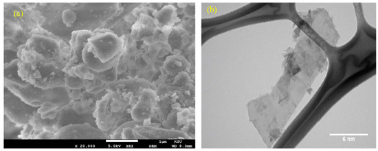
Figure 1.
Morphology of the received powder. (a) Al2O3 and GNPs; (b) GNPs (XG Sciences, Inc., USA).
Graphene nanoplatelets (GNPs), supplied by XG Sciences, Inc. (Lansing, MI, USA), were used as the reinforcement material. The characteristics of the GNPs are listed in Table 3. The morphology of the received GNP powder is shown in Figure 1b.

Table 3.
Characteristics of GNPs.
To fabricate the GNP-reinforced Al2O3 nanocomposites, the initial powder mixing was a critical step in ensuring the homogenous dispersion of the GNPs in the base Al2O3 powder. Several techniques mentioned in Table 1 are used for powder mixing. In this work, the planetary ball-milling technique was used to prepare the nanocomposites. All the powders (with or without GNPs) were mechanically ball-milled using the Pulverisette machine (FRITSCH GmbH, Idar-Oberstein, Germany). The GNP/Al2O3 nanocomposites were prepared using different weight percentages of reinforcement, including 0 wt.% (base Al2O3), 0.5 wt.%, 1 wt.%, 1.5 wt.%, and 2.5 wt.% GNPs. The GNP weight percentages were selected based on the preliminary experiments, which demonstrated that using a GNP wt.% of >2.5 led to compromised mechanical properties. The ball-milling was performed in cylindrical zirconia containers using yttria-stabilized zirconia balls (diameter = 15 mm) at 350 rpm for 4 h under a ball-to-powder weight ratio of 20:1 [39]. A schematic diagram of the ball-milling process of GNP-reinforced nanocomposites is illustrated in Figure 2a. The ball-milled powder was loaded into a graphite die with an internal diameter of 20 mm and then consolidated by an HFIHS furnace (HF Active Sinter System, ELTek CO., Gyeonggi-do, Republic of Korea), as shown in Figure 2b, at a temperature of 1500 °C, a heating rate of 150 °C/min, uniaxial pressure of 60 MPa, and a cooling rate of 200 °C/min in a vacuum (45-Torr) [10,30]. The dimensions of the fabricated specimens were 20 mm in diameter and 12 mm in height.
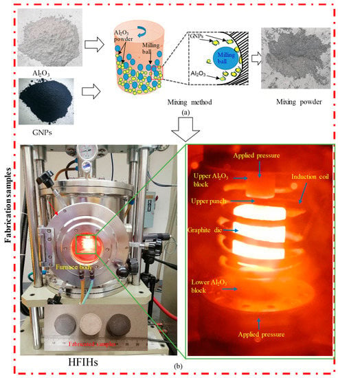
Figure 2.
Experimental setup for fabricating the GNP/Al2O3 specimens.
2.2. Machining and Measurements Setups
Laser microfabrication experiments were performed on the GNP/Al2O3 nanocomposites using an XTL-FP 20 laser machine from XT laser, Jinan, China, as shown in Figure 3a. This fiber laser requires very low power consumption (20 W). The laser beam was focused using a flat-field lens, moved through a galvanometric mirror system, and irradiated on the top surface of the fabricated GNP/Al2O3 specimens. Figure 3b shows a schematic diagram of laser beam machining. These types of laser sources have been designed specifically for the marking/engraving of metallic materials, such as steel and aluminum. In addition, they are adopted for different applications, such as surface treatments and micromachining operations. However, in this work, this low-power and low-cost laser machine was adapted for testing the machinability of the GNP/Al2O3 ceramic nanocomposites. It is worth mentioning that pure Al2O3 ceramic is extremely difficult to machine even with sophisticated high-power laser machines, such as that reported by [40]. Poor machining in terms of the microchannel shape and dimensions and the surface integrity have been reported even using expensive laser setups [40,41]. In this paper, it is shown that the addition of GNPs in Al2O3 enabled high-quality laser machining even with a very low cost, low power (20 W), and an easily accessible laser machine (XTL-FP 20 laser). This meets the requirements of clean, sustainable manufacturing where high-quality products (e.g., microchannels) can be produced with lower costs and resources.
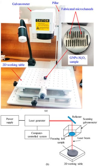
Figure 3.
(a) Laser beam machining setup; (b) schematic diagram of laser beam machining.
Microchannels with the dimensions of 250 µm in width and 5 mm in length were fabricated on all produced GNP/Al2O3 nanocomposites with varying GNP contents. Before the main experiments, all fabricated samples were ground to remove the superficial graphite and oxide layers and non-uniformity. Later, two laser parameters, i.e., the scanning speed and pulse frequency, were varied during the laser micro-milling. There is no information available in the literature regarding the laser micromachining of GNP/Al2O3 matrix nanocomposites. Therefore, initially, preliminary tests were conducted to identify the suitable ranges of influential factors using the reported studies on the micromachining of alumina ceramics [40,42,43]. Table 4 shows the selected laser parameters and their ranges.

Table 4.
Laser parameters and their selected ranges.
Parameters such as the power (20 W), scanning strategy (line strategy), and line spacing were kept constant throughout all the tests, as shown in Figure 4. In addition, to evaluate the effects of graphene content on the fabrication of microchannels, five specimens with 0.0 wt.%, 0.5 wt.%, 1 wt.%, 1.5 wt.%, and 2.5 wt.% GNPs were machined with the same laser parameters. Each test was repeated three times for each microchannel to guarantee the repeatability of the experiments, and later, the average value was used. The output responses, including the microchannels’ geometries (depth and top width), material removal rate, surface roughness, and surface morphology, were used to appraise the influence of the graphene contents on the micromachining behavior of the GNP/Al2O3 nanocomposites. After machining, all machined specimens were first cleaned using ethanol to remove any loose debris or contaminants on the fabricated microchannels [44]. Then, the dimensional accuracy and surface roughness were measured by a 3D optical profilometer (DektakXT Stylus Profiler) from Bruker (Billerica, MA, USA). The optical 3D profilometer was equipped with an inductive gauge of 12.5 μm radius diamond stylus, as shown in Figure 5a. The ablated depth and width were measured by capturing four random 2D profiles along the width of the fabricated channels with a scanning speed of 5 μm/s (see Figure 5c). The average of the measured values was used later to measure the dimensional accuracy (depth and width). The roughness was measured in terms of the arithmetic mean surface roughness ( according to the ISO 4287 standard. The surface roughness was measured by scanning four random measurements along the bottom length of the channels, and averaged values were used for further analysis (see Figure 5b). The surface morphologies of the machined microchannels were analyzed using a scanning electron microscope (SEM) from Jeol Japan (Model JCM 6000 Plus). Before capturing the SEM images, a platinum coating was applied to all machined samples using the JFC 1600 auto fine coater (JEOL Ltd., Tokyo, Japan) to enhance their visibility. The material removal rate (MRR) was used to assess the effect of the graphene contents on the laser micromachining of the nanocomposites. The MRR was calculated using Equation (1).
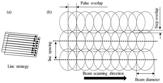
Figure 4.
(a) Laser scanning strategy; (b) schematic of the adjacent laser tracks.
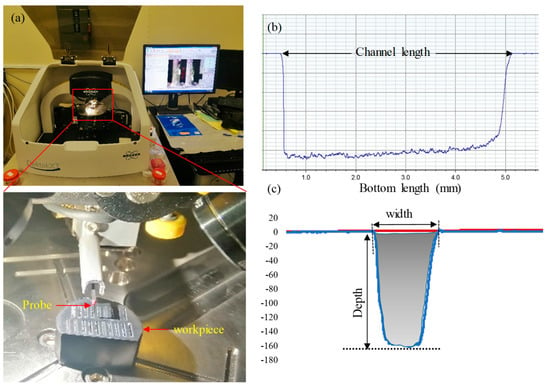
Figure 5.
Measuring devices. (a) Three-dimensional optical profilometer; (b,c) typical geometry of the 2D profile and its cross-sectional area.
The cross-section of the machined area was calculated from the fitted 2D profile, as shown by the grey-filled area in Figure 5c. The cross-sectional area of the four profiles was averaged and then used in Equation (1).
3. Results and Discussions
3.1. Characterization of the Fabricated GNP/Al2O3-Based Nanocomposites
3.1.1. Microstructure Evaluation
Figure 6 shows the morphologies of the fractured surfaces for the base Al2O3 and the GNP/Al2O3 nanocomposites. It can be seen that the GNP/Al2O3 nanocomposites had a smaller grain size compared to the base Al2O3. The addition of the GNPs tended to restrict grain growth by acting as an obstruction between the Al2O3 matrix particles.
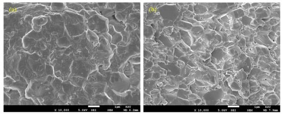
Figure 6.
SEM images showing the fractured surfaces of (a) base Al2O3; (b) 1.5 wt.% GNP/Al2O3.
3.1.2. Density Analysis
The actual density of the fabricated GNP/Al2O3 nanocomposites was measured using the Archimedes method by employing the density measurement system from Sartorius Lab Instruments, Goettingen, Germany. Afterward, the relative density was calculated by dividing the actual density by the theoretical density [45] of the powder mixture, as shown in Figure 7. It can be seen in Figure 7 that the fabricated GNP-reinforced Al2O3 nanocomposite samples exhibited a high relative density, which indicates good bonding between the GNPs and the Al2O3 matrix, with negligible porosity or cavities.
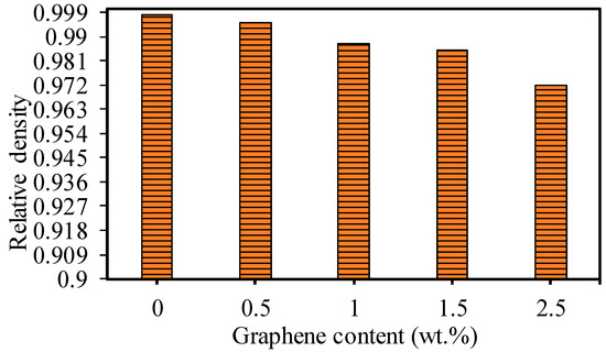
Figure 7.
Relative density of the base Al2O3 and GNP/Al2O3 nanocomposites with different GNP contents.
3.1.3. Hardness
The ZHV30 Vickers Hardness Tester was used to measure the Vickers hardness of the fabricated specimens using a load of 30 kg for a dwell time of 12 s. For each specimen, the hardness measurement was repeated six times at different locations on the ground surface, and later, the average value was used, as shown in Figure 8. It can be seen that nanocomposites with 0.5 wt.% GNPs had the highest hardness by approximately 7% compared to the base Al2O3. This can be attributed to the presence of GNPs among the Al2O3 particles, inhibiting grain growth and resulting in a smaller grain size and good interfacial bonding between the Al2O3 particles [10,16]. With GNP contents of 1 wt.% and 1.5 wt.%, the Vickers hardness slightly decreased. This can be attributed to the presence of the thicker layer of GNPs among the Al2O3 grains, which led to a weakening of the interfacial bonding between the Al2O3 particles and reduced hardness [1,10,16].
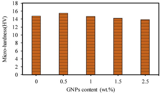
Figure 8.
Hardness for the base Al2O3 and GNP/Al2O3 nanocomposites.
3.2. Micromachining Results and Discussion
3.2.1. Surface Morphology
Figure 9, Figure 10, Figure 11 and Figure 12 show the surface morphologies of the laser-fabricated microchannels on the base Al2O3 and GNP/Al2O3 nanocomposites at lower (200 mm/s) and higher (500 mm/s) scan speeds. The results show that the microchannels of the GNP/Al2O3 nanocomposites had overall better surface quality and geometry compared to the base Al2O3 specimens in all machining conditions. This is because of the presence of the GNPs among the Al2O3 matrix particles, which enhanced the thermal conductivity and optical absorbance properties during the laser micromachining. These properties induced higher surface melting and evaporation at even lower energy densities. Kim et al. [46] found that the presence of CNT enhanced the machinability of CNT/Fe/Al2O3 nanocomposites due to the addition of the CNT, which led to lower light transmittance, higher thermal conductivity, and suppressed grain growth.
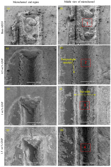
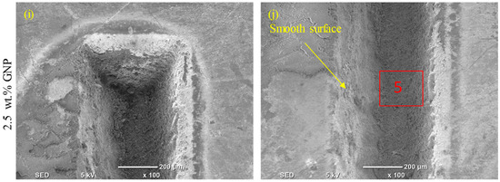
Figure 9.
Surface morphology of the ablated base Al2O3 and GNP/Al2O3 nanocomposites with varying graphene contents at 200 mm/s.
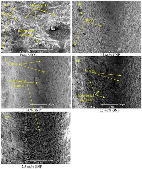
Figure 10.
Zoomed-in images of the selected regions (1–5) shown in Figure 9.
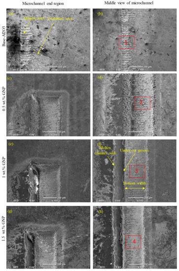
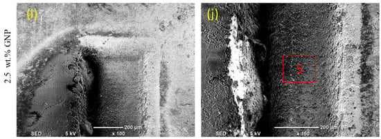
Figure 11.
Surface morphologies of the ablated base Al2O3 and GNP/Al2O3 nanocomposites with varying graphene contents at 500 mm/s.
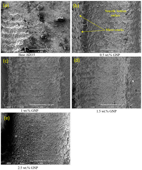
Figure 12.
Zoomed-in images of the selected regions (1–5) shown in Figure 11.
At a scan speed of 200 mm/s (see Figure 9), it can be seen that redeposited material, cracks, and pores were formed on the bottom surface of the microchannel and on the surrounding sidewalls in the case of the base Al2O3, as shown in Figure 9a,b and Figure 10a. On the contrary, a much more regular and smoother channel was observed for the nanocomposites with 0.5 wt.% GNPs at a scan speed of 200 mm/s, as can be seen in Figure 9c,d and Figure 10b. The surface morphology of the ablated microchannels shows a higher ablation with few cracks and pores on the bottom and sidewalls of the microchannels (see Figure 9c,d and Figure 10b). This can be attributed to the higher energy absorption of the nanocomposites, which required less energy for melting the surfaces of the specimens. For the 1 wt.% GNP specimens, the fabricated microchannels on the nanocomposites had visible and irregular redeposited materials and microcracks on the bottom surface at a scanning speed of 200 mm/s. In addition, the sidewalls of the microchannels became smoother with a marginal recast layer compared to the specimens with a 0.5 wt.% GNP content (see Figure 9e,f and Figure 10c). This was due to the increase in the GNP contents, which increased the optical absorbance of the specimens, causing more melting materials compared to the 0.5 wt.% GNP specimens. On the contrary, for the 1.5 wt.% GNP/Al2O3 nanocomposite, the surface morphology of the fabricated channel had a rough surface at a lower scanning speed of 200 mm/s compared to the 0.5 wt.% and 1 wt.% GNP specimens (see Figure 9g,h and Figure 10d). This was because of the lower ablation threshold energy for the 1 wt.% GNP specimens, which induced more melting material compared to the lower GNPs content. In addition, the increase in the GNP content resulted in an increase in the material’s thermal conductivity, which allowed the molten material at the bottom and sides of the microchannels to resolidify faster. This was observed as thicker re-solidified layers, microcracks, and pores around the side wall, and rougher bottom surfaces of the microchannels as the GNP wt.% increased. For the same reasons, the nanocomposites with 2.5 wt.% GNPs exhibited the worst surface morphology, with more redeposited material and pores compared to the 0.5 wt.%, 1 wt.%, and 1.5 wt.% GNP specimens, as shown in Figure 9i,j and Figure 10e.
At a high scanning speed of 500 mm/s, it was evident that no well-defined microchannels were created; instead, only multiple-pulse traces of the laser beam were seen on the base Al2O3 specimens. The base Al2O3 presented poor laser machinability compared to all of the GNP/Al2O3 nanocomposites, as shown in Figure 11a,b and Figure 12a. The laser-ablated nanocomposites with 0.5 wt.% GNPs showed well-defined microchannels. In addition, the ablated depths of the microchannels decreased, and some cracks, pores, and redeposited materials on the bottoms of the channels were formed, resulting in an increase in the surface roughness (see Figure 11c,d and Figure 12b). Moreover, it can be seen in the SEM images that the microchannel shape changed from triangular to trapezoidal with the increase in the scanning speed from 200 mm/s to 500 mm/s (compare Figure 9c and Figure 11c). For the 1 wt.%, 1.5 wt.%, and 2.5 wt.% GNP specimens, smoother surface morphologies were noted at 500 m/s compared to the 0.5 wt.% GNP specimens (see Figure 11e–j and Figure 12c–e), contrary to the scanning speed at 200 mm/s. This is because at a higher scanning speed (500 mm/s), the laser–workpiece interaction time was reduced, and samples with a higher ablation threshold (0.5 wt.% GNPs) were not adequately irradiated to melting and evaporation. As the GNP contents increased, the optical absorbance of the specimens increased, resulting in more molten and evaporated material from the walls and bottoms of the channels compared to the 0.5 wt.% GNP specimens (Figure 11i,j and Figure 12e).
3.2.2. Microchannel Accuracy
Figure 13a,b shows the effect of the GNP contents with varying scanning speeds on the channel depth and width. It can be concluded from Figure 13a that the channel depth increased with an increment in the GNP percentage from 0.0 wt.% to 2.5 wt.%. This is attributed to the improved thermal conductivity and optical absorbance of the GNP/Al2O3 nanocomposites, as discussed in Section 3.2.1 [31,39,47], leading to lowering the ablation threshold of the composites due to the addition of the GNPs. Therefore, the channel depth increased for the GNP/Al2O3 nanocomposites by around two to nine times compared to the base Al2O3. In addition, the channel depth increased with the increasing graphene contents from 0.5 wt.% to 2.5 wt.% due to further increases in the thermal conductivity, optical absorbance, and reduced grain size [48].
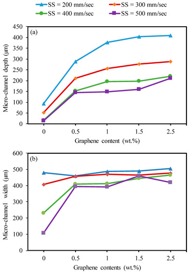
Figure 13.
Effects of varying graphene reinforcement contents with laser speed on microchannel depth and width for machining base Al2O3, and GNP/Al2O3 nanocomposites at F = 30 kHz. (a) Microchannel depth, (b) Microchannel depth.
At a higher scanning speed of 500 mm/s, the channel depth tended to decrease slightly with the GNP content rising from 1 wt.% to 1.5 wt.%, and then increased with the GNP content rising to 1.5 wt.%. The main reason for the improvement in the microchannel depth is shown in Figure 14. When the graphene content increased from 0.0 wt.% to 0.5 wt.%, more material melted, and less material was redeposited on the microchannel bed. Hence, the microchannel depth increased (see Figure 14b). When the graphene content increased from 0.5 wt.% to 1 wt.%, the microchannel depth increased because more induced materials were ablated, and few materials were redeposited on the microchannel bed, as can be seen by comparing Figure 14b,c. When the GNPs increased to 2.5 wt.%, the ablation threshold energy was reduced, which led to melting and more material redeposition on the machined surface. This was because there was a significant amount of thick graphene surrounding the Al2O3 particles (see Figure 14d,e) which efficiently transferred the heat away from the melting zone, causing redeposited materials on the beds and the sidewalls of the channels. Hence, these redeposited materials slightly increased the channel depth.
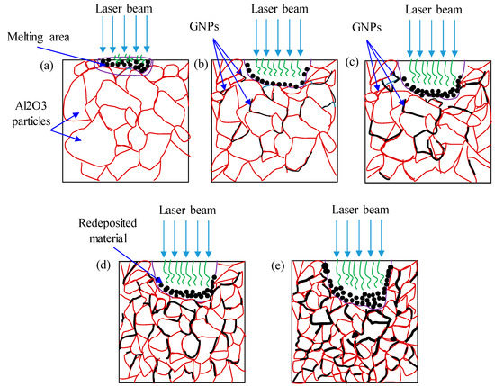
Figure 14.
Schematic diagram of laser beam machining, (a) base Al2O3; (b) 0.5 GNP/Al2O3 nanocomposites; (c) 1 wt.% GNP/Al2O3 nanocomposites; (d) 1.5 wt.% GNP/Al2O3; (e) 2.5 wt.% GNP/Al2O3 nanocomposites.
Figure 13b shows the impact of the graphene content with different scanning speeds on the microchannel widths of all fabricated samples. It can be seen that the results of the channel widths of the GNP/Al2O3 nanocomposites are similar in most of the machining conditions. However, some points could be noted. In the cases of the 1.5 wt.% and 2.5 wt.% GNP specimens, the width increased as the GNP content increased from 1 wt.% to 2.5 wt.% at a scanning speed of 400 mm/s. These results can be explained as follows. The absorption of the laser energy in the GNP nanocomposites increased with the increasing graphene content, which affected the melting process and the vaporization [38]. Therefore, at low scanning speeds of 200 mm/s and 300 mm/s, there was more interaction time between the laser and materials, leading to more molten material and rapid evaporation, which resulted in increased depths and stabilization of the widths, without any changes in any of the GNP/Al2O3 nanocomposites [49]. In the case of the high scanning speeds of 400 mm/s and 500 mm/s, it was expected that the nanocomposites with 1.5 wt.% and 2.5 wt.% GNPs would have a high absorption of energy compared to those with 0.5 wt.% and 1 wt.% GNPs, which resulted in more molten and evaporated materials from the walls and bottoms of the channels, leading to an increased width (see Figure 11a–j. However, in the case of the 2.5 wt.% GNP specimens, the width decreased at a scanning speed of 500 mm/s. This was because there was a significant amount of thick graphene surrounding the Al2O3 particles (see Figure 14e), which efficiently transferred the heat away from the melting zone, causing redeposited materials on the sidewalls of the channels. Hence, these redeposited materials reduced the channel width (as can clearly be seen in Figure 12e. In the case of the pure Al2O3, the width decreased as the scanning speed decreased. This happened because of the decrease in the absorption of energy, which led to a reduction in the melting and evaporation, resulting in a decreased width (see Figure 9a–i).
Figure 15 shows the trends of the impact of graphene contents on the microchannel depth and width at different levels of frequency. Regarding the effect of the GNPs, it can be concluded from Figure 15a that the nanocomposites reinforced with different graphene contents showed improvement in the channel depth compared to the base Al2O3. This trend was nearly the same as in the case of Figure 13. That is, the channel depth increased with increasing graphene contents from 0.5 wt.% to 2.5 wt.%. This is attributed to the optical absorbance and ablation threshold of the GNP/Al2O3 nanocomposites, which can be explained as follows. The pulse energy and pulse power identify the energy density and power density of the laser beam–material interaction mode and, therefore, the amount of machined volume. Leone et al. [41] found that the energy density was reduced with an increasing pulse frequency. The differences in the channel depth for the 20 kHz results in comparison to the higher frequencies can be seen as an indication of these changes. The presence of graphene among the alumina particles led to enhanced thermal conductivity and optical absorbance of the nanocomposites. However, these nanocomposites required a lower ablation threshold pulse energy for melting the materials compared to the base alumina. With an increasing frequency from 30 to 40 kHz, less material was molten during the ablation of the Al2O3 because the increasing frequency generated less energy. These results are in line with a reported study on the laser machining of Al2O3 [41]. However, in the cases of the 0.5 wt.%, 1 wt.%, 1.5 wt.%, and 2.5 wt.% GNP specimens, the graphene enhanced the effects of the increasing frequency on generating a lower energy density. Therefore, more material was ablated and removed from the bottom of the channel compared to the base Al2O3. However, an increased channel depth was obtained by the nanocomposites with 2.5 wt.% GNP contents. Kim et al. [46] reported that Al2O3 nanocomposites with higher CNT contents exhibited a higher ablation rate compared to those with low CNT contents due to lower light transmittance, higher thermal conductivity, and a smaller grain size. In the case of the 2.5 wt.% GNP specimens, the depth and width decreased at a frequency of 40 kHz due to the thick graphene, which conducted the heat away from the melting zone, leading to redeposited material on the wall and bottom (see Figure 14e).
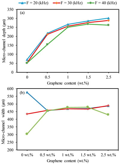
Figure 15.
Effects of the graphene reinforcements and frequency on the microchannel depth for machining base Al2O3 and GNP/Al2O3 nanocomposites (SS = 300 mm/s). (a) Microchannel depth, (b) Microchannel depth.
Regarding the effect of graphene content on the width, as shown in Figure 15b, the results are similar, and no obvious differences were observed in the width among the 0.5 wt.%, 1 wt.%, 1.5 wt.%, 2.5 wt.% GNP specimens. In the case of the base Al2O3, the width sharply decreased with increasing frequency due to less energy absorbance, as explained earlier.
To show the benefits of the GNP content on the laser machining of Al2O3, Figure 16 is provided, which shows the improvement in the ablation depth of the GNP/Al2O3 nanocomposites compared to the base Al2O3. It can be observed that the addition of GNPs enhanced the laser micromachining by increasing the ablation depth at lower and higher scanning speeds. For instance, at higher scanning speeds, the ablation depth was increased by 982%, 1004%, 1094%, and 1467% for the 0.5 wt.%, 1 wt.%, 1.5 wt.%, and 2.5 wt.% GNP/Al2O3 nanocomposites as compared to the base Al2O3 (see Figure 14). The results of the 2.5 wt.% GNP reinforcement exhibited the highest ablation depth during the laser beam micromachining.
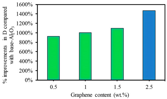
Figure 16.
Percentage of improvement in ablation depth at a higher scanning speed of 500 mm/s.
3.2.3. Surface Roughness
Figure 17 illustrates the trend of the effect of graphene contents at different scanning speeds on the surface roughness of the fabricated microchannels. Regarding the impact of the graphene, it can be seen that the specimens with 0.3 wt.% and 1wt.% GNPs had the tendency to generate the lowest surface roughness. This trend was the same as that shown in Figure 14. That is, the surface roughness increased with the increasing channel depth for the nanocomposites with 0.5 wt.%, 1 wt.%, 1.5 wt.%, and 2.5 wt.% GNPs. This is because the increase in the surface roughness with the increase in the depth occurred partly due to more molten materials, and evaporation caused the redeposited material, which affected the generated finished surface [44]. Perrie et al. [50] found that the surface roughness of the ablated microchannel increases with the machined depth due to the material redeposition. In some cases, the surface roughness tended to decrease slightly with the GNPs increasing from 1 wt.% to 1.5 wt.%. It should be noted that the formation of the laser-machined surface was mainly governed by the molten and evaporated material and was negatively affected by the redeposition of the molten material on the ablated area. The base Al2O3 exhibited the worst surface roughness compared to all other samples. The molten material and plume of the Al2O3 rapidly moved forward and backward inside the channel, so the propagating laser beam was absorbed and blocked by them [51]. Hence, the surface roughness was increased due to increased redeposition of molten and evaporating material.
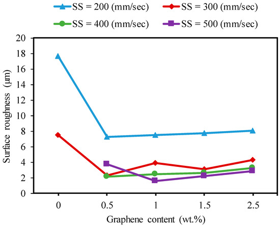
Figure 17.
Effects of the graphene reinforcements and laser speed on the surface roughness during the micro-milling of the base Al2O3, and GNP/Al2O3 nanocomposites (F = 30 kHz).
Regarding the effect of the scanning speed, Figure 17 shows that surface roughness significantly decreased with the scanning speed increasing from 100 mm/s to 500 mm/s for all samples in most of the machining conditions. This is because the laser energy per unit area decreased due to the reduced interaction time between the laser beam and material with an increase in the scanning speed. This resulted in fewer molten materials being deposited on the bottom surface [44].
It can be observed that the addition of GNPs enhanced the micromachining of alumina ceramic using a fiber laser with a minimum power of 20 watts. This was achieved by improving the surface quality at lower and higher scanning speeds. For example, at a lower scanning speed of 200 mm/s, the surface roughness levels decreased by 74%, 27%, 54%, and 31% for the 0.5 wt.%, 1 wt.%, 1.5 wt.%, and 2.5 wt.% GNP/Al2O3 nanocomposites, respectively, compared to the base Al2O3, as shown in Figure 18. At a higher scanning speed of 500 mm/s, higher-quality microchannels were fabricated on all GNP/Al2O3 nanocomposites. On the contrary, no ablated channels were fabricated on the base Al2O3 at the higher scanning speed of 500 mm/s.
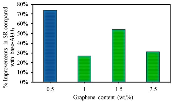
Figure 18.
Percentage of improvement in surface roughness at a lower scanning speed of 200 mm/s.
Regarding the effects of the frequency, Figure 19 presents the effects of the GNP contents with varying frequencies on the surface roughness of the microchannels. It can be observed in Figure 19 that the surface roughness increased with increases in the GNP contents from 0.5 wt.% to 1 wt.% and then decreased when the GNP contents increased to 1.5 wt.%. After that, the surface roughness increased with increasing GNPs to 2.5 wt.%. This trend was almost the same as in the case of the channel depth shown in Figure 13a. This is attributed to differences in the material properties of the developed nanocomposites. The nanocomposites with 0.5 wt.% GNPs had the lowest surface roughness compared to the base Al2O3 and the 1 wt.%, 1.5 wt.%, and 2.5% GNP/Al2O3 by approximately 287%, 132%, 28%, and 165%, respectively, at a lower frequency of 20 kHz. The 2.5 wt.% GNP nanocomposite exhibited higher surface roughness than all the other specimens. This happened because of the lower ablation threshold and optical absorption in the case of the 2.5 wt.% GNP specimens, which led to a higher ablation depth with an increase in the surface roughness due to redeposited material on the bottom surface of the channel.
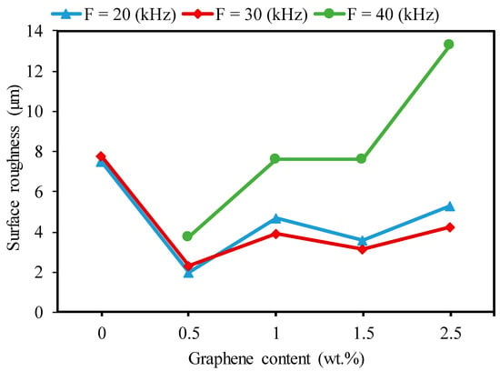
Figure 19.
Effects of the graphene reinforcements and frequency on surface roughness during the micro-milling of the base Al2O3 and GNP/Al2O3 nanocomposites (SS = 300 mm/s).
In general, it can be seen in Figure 19 that the surface roughness trend increased as the frequency increased from 20 kHz to 40 kHz for the 0.5 wt.% GNP/Al2O3. The low laser energy caused more unmolten materials to be deposited at the bottom of the fabricated microchannels, which affected the roughness of the ablated surface [40,49]. In addition, Figure 20 shows that the roughness decreased by increasing the frequency to 30 kHz from 20 kHz in the case of the 1 wt.%, 1.5 wt.%, and 2.5 wt.% GNP/Al2O3. This was expected due to their higher thermal resistance, smaller grain size, and lower light transmittance compared to the 0.5 wt.% GNP/Al2O3. At the frequency of 20 kHz, excessive energy was generated, and more materials were molten and evaporated, which led to a redeposit of molten material on the surface [49].
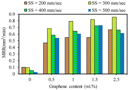
Figure 20.
Effects of varying graphene contents with laser speed on MRR. At F = 30 kHz.
3.2.4. Material Removal Rate
Figure 20 shows the effects of the GNP contents and laser scanning speed on the material removal rates of the base Al2O3 and GNP/Al2O3 nanocomposites. From the experimental findings, it was noted that the MRR was affected by the graphene contents. The MRR results are remarkably improved in the laser micromachining of all GNP/Al2O3 nanocomposites compared to the base Al2O3 ceramics. It can be observed in Figure 20 that the MRR values increased with increasing GNP contents from 0.5 wt.% to 1.5 wt.% in the micro-milling of the GNP/Al2O3 nanocomposites in most of the machining conditions. This is because the increase in the GNP content corresponded to lower light transmittance, higher thermal conductivity of the nanocomposite, and consequently, a higher ablation rate. In addition, this trend was almost the same as in the case of the microchannel depth. However, in the case of the 2.5 wt.% GNPs, the MRR decreased when the scanning speed increased to 500 mm/s from 300 mm/s compared to the 1.5 wt.% GNP specimens. This occurred because more material melted and was then deposited along the bottom and microchannel edges, which led to a change in the size of the machined channel (see Figure 9 and Figure 11).
In general, it can be seen in Figure 20 that the MRR tended to decrease as the scanning speed increased from 300 mm/s to 500 m/min for all fabricated samples. This is attributed to the fact that increasing the scanning speed led to reducing the interaction time between the laser and materials. Thus, the ablated materials decreased, resulting in a lower MRR, as discussed by [40,45]. In addition, it can be seen that the MRR increased when the scanning speed increased from 200 mm/s to 300 mm/s for all of the GNP/Al2O3 samples. Although the triangular microchannels were shaped at a lower scanning speed (200 mm/s), when the scanning speed was raised to 300 mm/s and higher, the shape of the microchannels changed from triangular to trapezoidal, with a large bottom width and less depth (see Figure 9 and Figure 11), which indicates a higher ablation rate compared to the lower scanning speed. These results are consistent with a previous study by [45].
To show the effects of adding GNP contents on the laser micromachining of Al2O3, Figure 21 is presented, which shows the improvement in the MRR of the GNP/Al2O3 nanocomposites compared to the base Al2O3. For example, at a lower scanning speed of 200 mm/s, the MRRs increased by 375.40%, 459.18%, 459.26%, and 581.788% for the 0.5 wt.%, 1 wt.%, 1.5 wt.%, and 2.5 wt.% GNP/Al2O3 nanocomposites, respectively, compared to the base Al2O3. At a higher scanning speed of 500 mm/s, the MRRs increased by 2134%, 2391%, 2915%, and 2427% for the 0.5 wt.%, 1 wt.%, 1.5 wt.%, and 2.5 wt.% GNP/Al2O3 nanocomposites, respectively, compared to the base Al2O3, as shown in Figure 21.
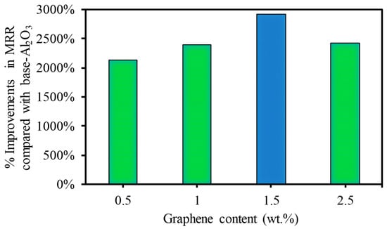
Figure 21.
Percentages of improvement in MRR at a higher scanning speed of 500 mm/s.
4. Conclusions
In this study, GNP/Al2O3 matrix nanocomposites consisting of 0 wt.%, 0.5 wt.%, 1 wt.%, 1.5 wt.%, and 2.5 wt.% GNPs were successfully fabricated using powder metallurgy and the HFIHS technique. The influence of the GNP contents on the micromachining performance of the fabricated nanocomposites was investigated. Based on the experimental findings, the following conclusions are drawn:
- All of the produced GNP-based Al2O3 nanocomposite samples exhibited high relative densities between 97.17% and 99.79%, which indicates good bonding between the GNPs and the Al2O3 matrix without porosity or cavities.
- The hardness was moderately affected by the GNP reinforcement in the Al2O3 matrix. Nanocomposites with 0.5 wt.% GNPs demonstrated a slight improvement in hardness by approximately 6.3% compared to the base Al2O3. In comparison, other nanocomposites exhibited a slight decrease in hardness.
- The SEM examination revealed that the inclusion of graphene contents had a profound influence on the surface morphology of the machined microchannels. The base Al2O3 samples showed inferior surface quality, with pores, more redeposited materials, and microcracks. All of the GNP/ Al2O3 nanocomposites showed improvement in morphology compared to the base Al2O3 samples. This was due to the lower ablation threshold energy of the graphene based-nanocomposites.
- The ablation depth was significantly affected by the GNP reinforcement. The GNP/Al2O3 nanocomposites exhibited improvement in the ablation depth compared to the base Al2O3 in all machining conditions. For example, at a scanning speed of 500 mm/s, the ablation depths increased by 9.8, 10.04, 10.9, and 14.6 times, respectively, compared to the base Al2O3. This was because the graphene reinforcements reduced the ablation threshold energy required to induce the materials and increased the material removal efficiency due to higher optical absorbance, thermal conductivity, and a smaller grain size.
- The MRRs during the laser micromachining were significantly affected by the GNP reinforcement in the Al2O3 matrix. For example, at a higher scanning speed, the MRRs were increased by 2134%, 2391%, 2915%, and 2427% for the 0.5 wt.%, 1 wt.%, 1.5 wt.%, and 2.5 wt.% GNP/Al2O3 nanocomposites, respectively, compared to the base Al2O3 ceramic.
- The roughness of the machined microchannels was affected by the GNP reinforcement. The nanocomposites with lower GNP contents exhibited the lowest surface roughness compared to the other samples. Among the machined nanocomposites, the 0.5 wt.% GNP samples showed the lowest surface roughness.
- Overall, the microchannel accuracy, surface quality, and material removal rate were significantly affected by the GNP reinforcement in the alumina matrix nanocomposites during the laser micromachining. It is worth stating again that all of the GNP-reinforced alumina matrix nanocomposites showed improved micromachining performance compared to the unreinforced samples. Moreover, by comparing the influence of the GNP reinforcements on the surface roughness and surface morphology, the nanocomposites with 0.3 wt.% and 1wt.% GNPs largely showed better performance in most of the machining conditions, while the nanocomposites with 1.5 wt.% and 2.5 wt.% GNPs showed better machining performance regarding the ablation rate and material removal rate. The results show that GNP/Al2O3 nanocomposites can be machined with very good quality using a very ordinary 20 W fiber laser. In contrast, pure Al2O3 could not be machined using the same low-power and low-budget laser system. This helps in achieving the clean and sustainable manufacturing goals with reduced energy consumption for clean environment.
Author Contributions
Conceptualization, M.M.N.; methodology, M.M.N. and S.A.; software, M.M.N.; validation, M.M.N., S.A., and A.M.A.-S.; formal analysis, M.M.N., S.A. and A.M.A.-S.; investigation, M.M.N., S.A., K.N.A., A.D. and M.H.A.; resources, A.M.A.-S.; data curation, M.M.N. and S.A.; writing—original draft preparation, M.M.N.; writing—review and editing, M.M.N., S.A. and K.N.A.; visualization, M.M.N.; supervision, S.A., A.M.A.-S. and K.N.A. All authors have read and agreed to the published version of the manuscript.
Funding
Deputyship for Research & Innovation, Ministry of Education in Saudi Arabia project no. (IFKSURG-2-804).
Data Availability Statement
The data are available on request from corresponding author.
Acknowledgments
The authors extend their appreciation to the Deputyship for Research & Innovation, Ministry of Education in Saudi Arabia for funding this research work through the project no. (IFKSURG-2-804).
Conflicts of Interest
The authors declare no conflict of interest.
References
- Ahmad, I.; Anwar, S.; Xu, F.; Zhu, Y. Tribological Investigation of Multilayer Graphene Reinforced Alumina Ceramic Nanocomposites. J. Tribol. 2019, 141, 022002. [Google Scholar] [CrossRef]
- Brandner, J.J. Fabrication of Microreactors Made from Metals and Ceramics. In Microreactors in Organic Synthesis and Catalysis; Wiley-VCH Verlag GmbH & Co. KGaA: Weinheim, Germany, 2008; pp. 1–17. [Google Scholar]
- Abdo, B.M.A.; Anwar, S.; El-Tamimi, A.M.; Nasr, E.A. Experimental Analysis on the Influence and Optimization of μ-RUM Parameters in Machining Alumina Bioceramic. Materials 2019, 12, 616. [Google Scholar] [CrossRef] [PubMed]
- Sommers, A.; Wang, Q.; Han, X.; T’Joen, C.; Park, Y.; Jacobi, A. Ceramics and Ceramic Matrix Composites for Heat Exchangers in Advanced Thermal Systems—A Review. Appl. Therm. Eng. 2010, 30, 1277–1291. [Google Scholar] [CrossRef]
- Sternitzke, M.; Derby, B.; Brook, R.J. Alumina/Silicon Carbide Nanocomposites by Hybrid Polymer/Powder Processing: Microstructures and Mechanical Properties. J. Am. Ceram. Soc. 1998, 81, 41–48. [Google Scholar] [CrossRef]
- Morisada, Y.; Miyamoto, Y.; Takaura, Y.; Hirota, K.; Tamari, N. Mechanical Properties of SiC Composites Incorporating SiC-Coated Multi-Walled Carbon Nanotubes. Int. J. Refract. Met. Hard Mater. 2007, 25, 322–327. [Google Scholar] [CrossRef]
- Grigoriev, S.; Peretyagin, P.; Smirnov, A.; Solís, W.; Díaz, L.A.; Fernández, A.; Torrecillas, R. Journal of the European Ceramic Society Effect of Graphene Addition on the Mechanical and Electrical Properties of Al2O3-SiCw Ceramics. J. Eur. Ceram. Soc. 2017, 37, 2473–2479. [Google Scholar] [CrossRef]
- Llorca, J.; Elices, M.; Celemín, J.A. Toughness and Microstructural Degradation at High Temperature in SiC Fiber-Reinforced Ceramics. Acta Mater. 1998, 46, 2441–2453. [Google Scholar] [CrossRef]
- Fu, Y.; Gu, Y.W.; Du, H. SiC Whisker Toughened Al2O3-(Ti,W)C Ceramic Matrix Composites. Scr. Mater. 2001, 44, 111–116. [Google Scholar] [CrossRef]
- Ahmad, I.; Islam, M.; Sayed, H.; Subhani, T.; Abdelrazek, K.; Almajid, A.A.; Yazdani, B.; Zhu, Y. Toughening Mechanisms and Mechanical Properties of Graphene Nanosheet-Reinforced Alumina. Mater. Des. 2015, 88, 1234–1243. [Google Scholar] [CrossRef]
- Shah, W.A.; Luo, X.; Guo, C.; Rabiu, B.I.; Huang, B.; Yang, Y.Q. Preparation and Mechanical Properties of Graphene-Reinforced Alumina-Matrix Composites. Chem. Phys. Lett. 2020, 754, 137765. [Google Scholar] [CrossRef]
- Nasr, M.M.; Anwar, S.; Al-Samhan, A.M.; Abdo, H.S.; Dabwan, A. On the Machining Analysis of Graphene Nanoplatelets Reinforced Ti6Al4V Matrix Nanocomposites. J. Manuf. Process. 2021, 61, 574–589. [Google Scholar] [CrossRef]
- Cygan, T.; Petrus, M.; Wozniak, J.; Cygan, S.; Teklińska, D.; Kostecki, M.; Jaworska, L.; Olszyna, A. Mechanical Properties and Tribological Performance of Alumina Matrix Composites Reinforced with Graphene-Family Materials. Ceram. Int. 2020, 46, 7170–7177. [Google Scholar] [CrossRef]
- Rivero-Antúnez, P.; Zamora-Ledezma, C.; Sánchez-Bajo, F.; Moreno-López, J.C.; Anglaret, E.; Morales-Flórez, V. Sol–Gel Method and Reactive SPS for Novel Alumina–Graphene Ceramic Composites. J. Eur. Ceram. Soc. 2023, 43, 1064–1077. [Google Scholar] [CrossRef]
- Shah, W.A.; Luo, X.; Yang, Y.Q. Mechanical and Thermal Properties of Spark Plasma Sintered Al2O3-Graphene-SiC Hybrid Composites. Ceram. Int. 2023, 49, 7987–7995. [Google Scholar] [CrossRef]
- Kuşoğlu, I.M.; Çavdar, U.; Altintaş, A. The Effects of Graphene Nanoplatelet Addition to in Situ Compacted Alumina Nanocomposites Using Ultra-High Frequency Induction Sintering System. J. Aust. Ceram. Soc. 2020, 56, 233–241. [Google Scholar] [CrossRef]
- Nieto, A.; Bisht, A.; Lahiri, D.; Zhang, C.; Agarwal, A. Graphene Reinforced Metal and Ceramic Matrix Composites: A Review. Int. Mater. Rev. 2017, 62, 241–302. [Google Scholar] [CrossRef]
- Mudra, E.; Shepa, I.; Hrubovcakova, M.; Koribanich, I.; Medved, D.; Kovalcikova, A.; Vojtko, M.; Dusza, J. Highly Wear-Resistant Alumina/Graphene Layered and Fiber-Reinforced Composites. Wear 2021, 484–485, 204026. [Google Scholar] [CrossRef]
- Shah, W.A.; Luo, X.; Rabiu, B.I.; Huang, B.; Yang, Y.Q. Toughness Enhancement and Thermal Properties of Graphene-CNTs Reinforced Al2O3 Ceramic Hybrid Nanocomposites. Chem. Phys. Lett. 2021, 781, 138978. [Google Scholar] [CrossRef]
- Duntu, S.H.; Hukpati, K.; Ahmad, I.; Islam, M.; Boakye-Yiadom, S. Deformation and Fracture Behaviour of Alumina-Zirconia Multi-Material Nanocomposites Reinforced with Graphene and Carbon Nanotubes. Mater. Sci. Eng. A 2022, 835, 142655. [Google Scholar] [CrossRef]
- Wang, X.; Zhao, J.; Cui, E.; Tian, X.; Sun, Z. Effect of Interfacial Structure on Mechanical Properties of Graphene Reinforced Al2O3–WC Matrix Ceramic Composite. Nanomaterials 2021, 11, 1374. [Google Scholar] [CrossRef]
- Liang, L.; Huang, C.; Wang, C.; Sun, X.; Yang, M.; Wang, S.; Cheng, Y.; Ning, Y.; Li, J.; Yin, W.; et al. Ultratough Conductive Graphene/Alumina Nanocomposites. Compos. Part A Appl. Sci. Manuf. 2022, 156, 106871. [Google Scholar] [CrossRef]
- He, T.; Li, J.; Wang, L.; Zhu, J.; Jiang, W. Preparation and Consolidation of Alumina/Graphene Composite Powders. Mater. Trans. 2009, 50, 749–751. [Google Scholar] [CrossRef]
- Wang, K.; Wang, Y.; Fan, Z.; Yan, J.; Wei, T. Preparation of Graphene Nanosheet/Alumina Composites by Spark Plasma Sintering. Mater. Res. Bull. 2011, 46, 315–318. [Google Scholar] [CrossRef]
- Porwal, H.; Tatarko, P.; Grasso, S.; Khaliq, J.; Dlouhý, I.; Reece, M.J. Graphene Reinforced Alumina Nano-Composites. Carbon 2013, 64, 359–369. [Google Scholar] [CrossRef]
- Chen, Y.F.; Bi, J.Q.; Yin, C.L.; You, G.L. Microstructure and Fracture Toughness of Graphene Nanosheets/Alumina Composites. Ceram. Int. 2014, 40, 13883–13889. [Google Scholar] [CrossRef]
- Liu, X.; Fan, Y.-C.; Li, J.-L.; Wang, L.-J.; Jiang, W. Preparation and Mechanical Properties of Graphene Nanosheet Reinforced Alumina Composites. Adv. Eng. Mater. 2015, 17, 28–35. [Google Scholar] [CrossRef]
- Kim, W.; Oh, H.S.; Shon, I.J. The Effect of Graphene Reinforcement on the Mechanical Properties of Al2O3ceramics Rapidly Sintered by High-Frequency Induction Heating. Int. J. Refract. Met. Hard Mater. 2015, 48, 376–381. [Google Scholar] [CrossRef]
- Liu, J.; Yang, Y.; Hassanin, H.; Jumbu, N.; Deng, S.; Zuo, Q.; Jiang, K. Graphene–Alumina Nanocomposites with Improved Mechanical Properties for Biomedical Applications. ACS Appl. Mater. Interfaces 2016, 8, 2607–2616. [Google Scholar] [CrossRef]
- Ahmad, I.; Subhani, T.; Wang, N.; Zhu, Y. Thermophysical Properties of High-Frequency Induction Heat Sintered Graphene Nanoplatelets/Alumina Ceramic Functional Nanocomposites. J. Mater. Eng. Perform. 2018, 27, 2949–2959. [Google Scholar] [CrossRef]
- Fan, Y.; Wang, L.; Li, J.; Li, J.; Sun, S.; Chen, F.; Chen, L.; Jiang, W. Preparation and Electrical Properties of Graphene Nanosheet/Al2O3 Composites. Carbon 2010, 48, 1743–1749. [Google Scholar] [CrossRef]
- Porwal, H.; Kasiarova, M.; Tatarko, P.; Grasso, S.; Dusza, J.; Reece, M.J. Scratch Behaviour of Graphene Alumina Nanocomposites. Adv. Appl. Ceram. 2015, 114, S34–S41. [Google Scholar] [CrossRef]
- Yazdani, B.; Porwal, H.; Xia, Y.; Yan, H.; Reece, M.J.; Zhu, Y. Role of Synthesis Method on Microstructure and Mechanical Properties of Graphene/Carbon Nanotube Toughened Al2O3 Nanocomposites. Ceram. Int. 2015, 41, 9813–9822. [Google Scholar] [CrossRef]
- Sung, J.W.; Kim, K.H.; Kang, M.C. Effects of Graphene Nanoplatelet Contents on Material and Machining Properties of GNP-Dispersed Al2O3 Ceramics for Micro-Electric Discharge Machining. Int. J. Precis. Eng. Manuf.-Green Technol. 2016, 3, 247–252. [Google Scholar] [CrossRef]
- Nieto, A.; Zhao, J.M.; Han, Y.H.; Hwang, K.H.; Schoenung, J.M. Microscale tribological behavior and in vitro biocompatibility of graphene nanoplatelet reinforced alumina. J. Mech. Behav. Biomed. Mater. 2016, 61, 122–134. [Google Scholar] [CrossRef] [PubMed]
- Liu, J.; Camfield, R. Machinability Experimental Study of Sintered Alumina (Al2O3) Ceramics Material by Chemical Vapor Deposition Diamond Coating Milling Tools. Proc. Inst. Mech. Eng. Part B J. Eng. Manuf. 2015, 229, 1535–1546. [Google Scholar] [CrossRef]
- Abdo, B.M.A.; Ahmed, N.; El-Tamimi, A.M.; Anwar, S.; Alkhalefah, H.; Nasr, E.A. Laser Beam Machining of Zirconia Ceramic: An Investigation of Micro-Machining Geometry and Surface Roughness. J. Mech. Sci. Technol. 2019, 33, 1817–1831. [Google Scholar] [CrossRef]
- Lee, J.Y.; Kang, M.C.; Kim, K.H.; Park, W.I.; Cho, S.H. Effects of Optical Absorbance with Ablation Characteristics in Femtosecond Laser Irradiation of Carbon Reinforced Al2O3 Composites. Adv. Appl. Ceram. 2016, 115, 123–128. [Google Scholar] [CrossRef]
- López-Pernía, C.; Muñoz-Ferreiro, C.; González-Orellana, C.; Morales-Rodríguez, A.; Gallardo-López; Poyato, R. Optimizing the Homogenization Technique for Graphene Nanoplatelet/Yttria Tetragonal Zirconia Composites: Influence on the Microstructure and the Electrical Conductivity. J. Alloys Compd. 2018, 767, 994–1002. [Google Scholar] [CrossRef]
- Abdo, B.M.A.; Anwar, S.; El-Tamimi, A.M.; Alahmari, A.M.; Abouel Nasr, E. Laser Micro-Milling of Bio-Lox Forte Ceramic: An Experimental Analysis. Precis. Eng. 2018, 53, 179–193. [Google Scholar] [CrossRef]
- Leone, C.; Genna, S.; Tagliaferri, F.; Palumbo, B.; Dix, M. Experimental Investigation on Laser Milling of Aluminium Oxide Using a 30 W Q-Switched Yb:YAG Fiber Laser. Opt. Laser Technol. 2016, 76, 127–137. [Google Scholar] [CrossRef]
- Zhang, X.; Ji, L.; Zhang, L.; Wang, W.; Yan, T. Polishing of Alumina Ceramic to Submicrometer Surface Roughness by Picosecond Laser. Surf. Coat. Technol. 2020, 397, 125962. [Google Scholar] [CrossRef]
- Preusch, F.; Adelmann, B.; Hellmann, R. Micromachining of AlN and Al2O3 Using Fiber Laser. Micromachines 2014, 5, 1051–1060. [Google Scholar] [CrossRef]
- Deng, D.; Xie, Y.; Chen, L.; Chen, X. Experimental Investigation on Laser Micromilling of SiC Microchannels. Int. J. Adv. Manuf. Technol. 2019, 101, 9–21. [Google Scholar] [CrossRef]
- Agarwal, B.D.; Broutman, L.J.; Chandrashekhara, K. Analysis and Performance of Fiber Composites; John Wiley & Sons: Hoboken, NJ, USA, 2006. [Google Scholar]
- Kim, K.R.; Choi, B.D.; Yi, J.S.; Cho, S.H.; Choa, Y.H.; Shin, D.S.; Bae, D.H.; Kang, M.C.; Jeong, Y.K. Laser Micromachining of CNT/Fe/Al2O3 Nanocomposites. Trans. Nonferrous Met. Soc. China 2009, 19, s189–s193. [Google Scholar] [CrossRef]
- Kumari, L.; Zhang, T.; Du, G.H.; Li, W.Z.; Wang, Q.W.; Datye, A.; Wu, K.H. Thermal Properties of CNT-Alumina Nanocomposites. Compos. Sci. Technol. 2008, 68, 2178–2183. [Google Scholar] [CrossRef]
- Li, Q.; Zhang, Y.; Gong, H.; Sun, H.; Li, T.; Guo, X.; Ai, S. Effects of Graphene on the Thermal Conductivity of Pressureless-Sintered SiC Ceramics. Ceram. Int. 2015, 41, 13547–13552. [Google Scholar] [CrossRef]
- Xing, Y.; Liu, L.; Wu, Z.; Wang, X.; Huang, P.; Tang, L. Fabrication and Characterization of Micro-Channels on Al2O3/TiC Ceramic Produced by Nanosecond Laser. Ceram. Int. 2018, 44, 23035–23044. [Google Scholar] [CrossRef]
- Perrie, W.; Rushton, A.; Gill, M.; Fox, P.; O’Neill, W. Femtosecond Laser Micro-Structuring of Alumina Ceramic. Appl. Surf. Sci. 2005, 248, 213–217. [Google Scholar] [CrossRef]
- Kim, K.R.; Kim, J.H.; Kim, K.H.; Niihara, K.; Jeong, Y.K. Laser Microfabrication of Alumina-Silicon Carbide Nanocomposites. J. Ceram. Process. Res. 2008, 9, 421–424. [Google Scholar]
Disclaimer/Publisher’s Note: The statements, opinions and data contained in all publications are solely those of the individual author(s) and contributor(s) and not of MDPI and/or the editor(s). MDPI and/or the editor(s) disclaim responsibility for any injury to people or property resulting from any ideas, methods, instructions or products referred to in the content. |
© 2023 by the authors. Licensee MDPI, Basel, Switzerland. This article is an open access article distributed under the terms and conditions of the Creative Commons Attribution (CC BY) license (https://creativecommons.org/licenses/by/4.0/).