
Mechanistic Insights into Electronic Current Flow through Quinone Devices


Abstract
:1. Introduction
2. Methods
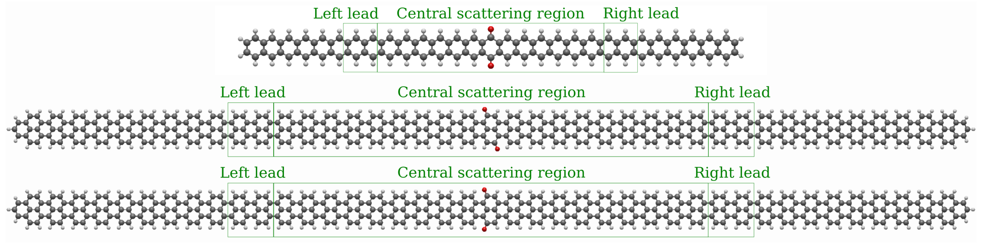
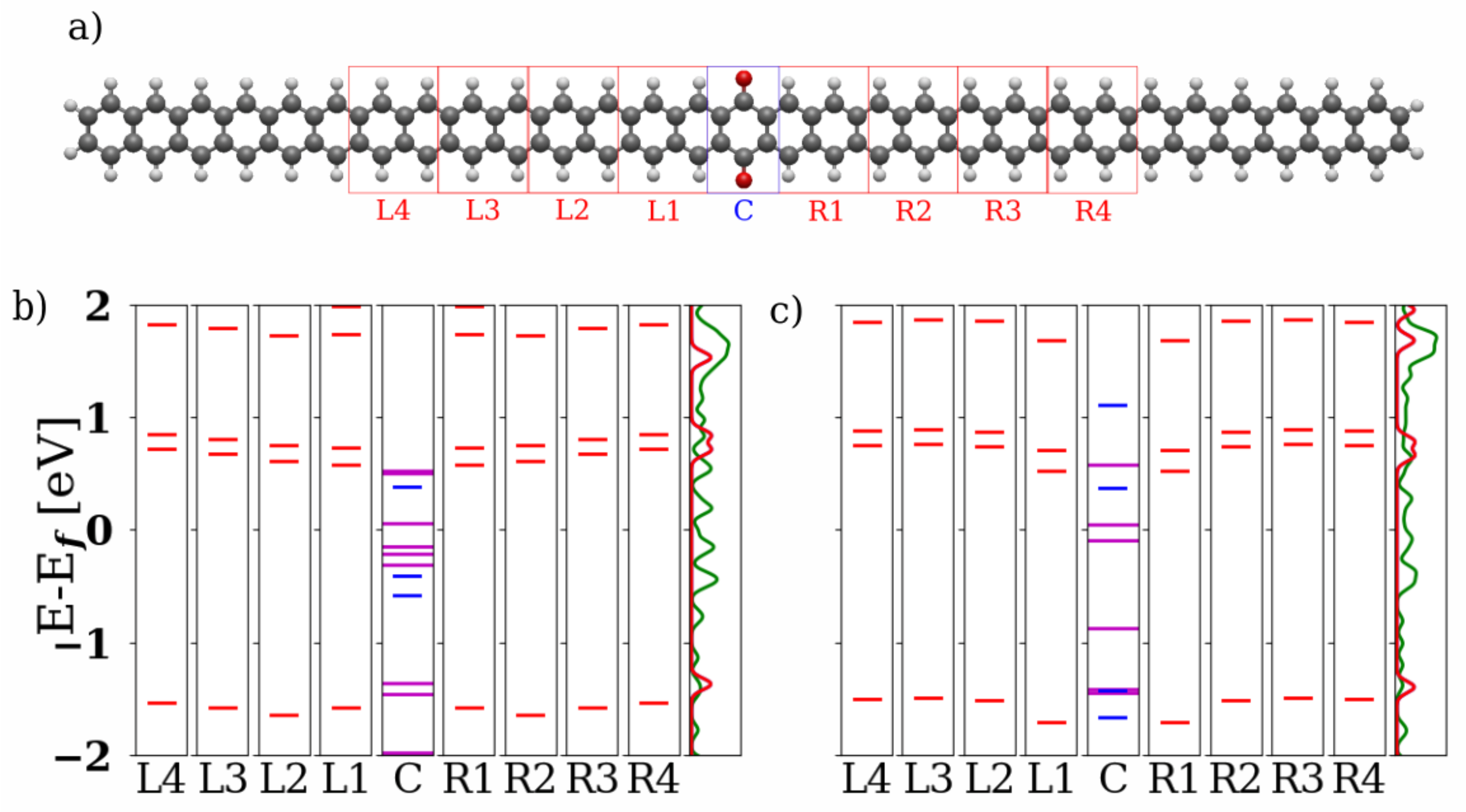
2.1. Models
2.2. Computational Details
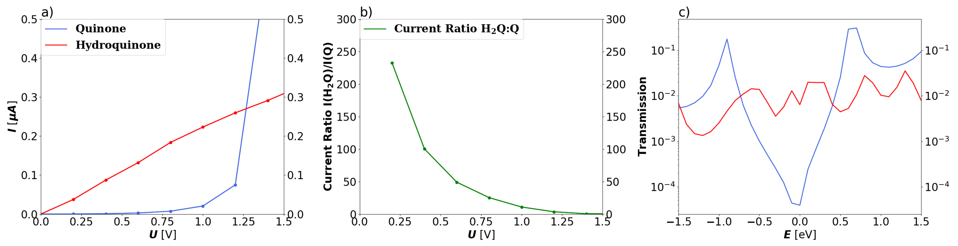
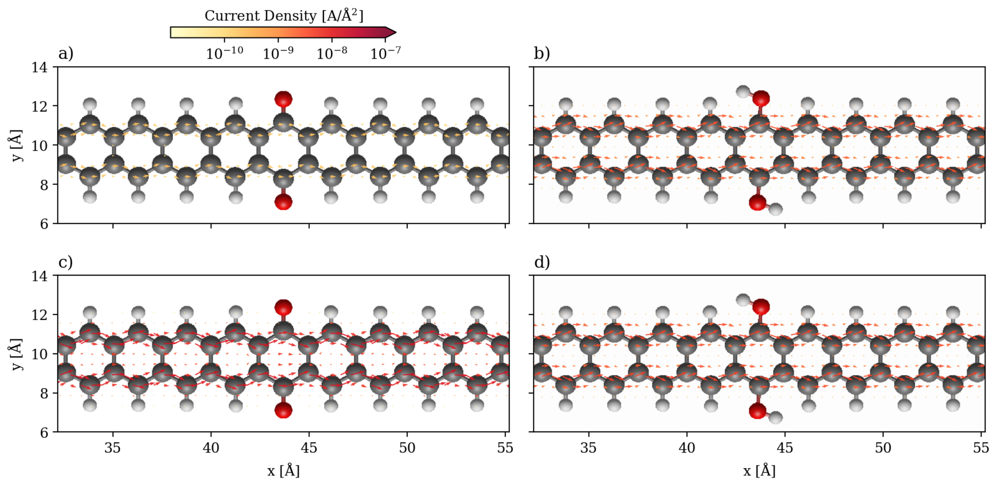
3. Results and Discussion
3.1. Devices Based on Zigzag Graphene Nanoribbons
3.2. Devices Based on Armchair Graphene Nanoribbons
4. Conclusions
Supplementary Materials
Author Contributions
Funding
Data Availability Statement
Conflicts of Interest
References
- Novoselov, K.S.; Geim, A.K.; Morozov, S.V.; Jiang, D.; Zhang, Y.; Dubonos, S.V.; Grigorieva, I.V.; Firsov, A.A. Electric Field Effect in Atomically Thin Carbon Films. Science 2004, 306, 666–669. [Google Scholar] [CrossRef] [PubMed]
- Castro Neto, A.H.; Guinea, F.; Peres, N.M.R.; Novoselov, K.S.; Geim, A.K. The Electronic Properties of Graphene. Rev. Mod. Phys. 2009, 81, 109–162. [Google Scholar] [CrossRef]
- Geim, A.K. Graphene: Status and Prospects. Science 2009, 324, 1530–1534. [Google Scholar] [CrossRef] [PubMed]
- de Heer, W.A.; Berger, C. Epitaxial Graphene. J. Phys. D Appl. Phys. 2012, 45, 150301. [Google Scholar] [CrossRef]
- Sutter, P. How Silicon Leaves the Scene. Nat. Mater. 2009, 8, 171–172. [Google Scholar] [CrossRef] [PubMed]
- Mohanty, N.; Moore, D.; Xu, Z.; Sreeprasad, T.; Nagaraja, A.; Rodriguez, A.A.; Berry, V. Nanotomy-Based Production of Transferable and Dispersible Graphene Nanostructures of Controlled Shape and Size. Nat. Commun. 2012, 3, 844. [Google Scholar] [CrossRef] [PubMed]
- Cunha, E.; Proença, F.; Costa, F.; Fernandes, A.; Ferro, M.; Lopes, P.; González-Debs, M.; Melle-Franco, M.; Francis, L.; Paiva, M. Self-Assembled Functionalized Graphene Nanoribbons from Carbon Nanotubes. ChemistryOpen 2015, 4, 115–119. [Google Scholar] [CrossRef]
- Jacobberger, R.M.; Kiraly, B.; Fortin-Deschenes, M.; Levesque, P.L.; McElhinny, K.M.; Brady, G.J.; Rojas Delgado, R.; Singha Roy, S.; Mannix, A.; Lagally, M.G.; et al. Direct Oriented Growth of Armchair Graphene Nanoribbons on Germanium. Nat. Commun. 2015, 6, 8006. [Google Scholar] [CrossRef]
- Cai, J.; Ruffieux, P.; Jaafar, R.; Bieri, M.; Braun, T.; Blankenburg, S.; Muoth, M.; Seitsonen, A.P.; Saleh, M.; Feng, X.; et al. Atomically precise bottom-up fabrication of graphene nanoribbons. Nature 2010, 466, 470–473. [Google Scholar] [CrossRef]
- Barone, V.; Hod, O.; Scuseria, G.E. Electronic Structure and Stability of Semiconducting Graphene Nanoribbons. Nano Lett. 2006, 6, 2748–2754. [Google Scholar] [CrossRef] [PubMed]
- Chung, H.C.; Chang, C.P.; Lin, C.Y.; Lin, M.F. Electronic and Optical Properties of Graphene Nanoribbons in External Fields. Phys. Chem. Chem. Phys. 2016, 18, 7573–7616. [Google Scholar] [CrossRef]
- Son, Y.W.; Cohen, M.L.; Louie, S.G. Energy Gaps in Graphene Nanoribbons. Phys. Rev. Lett. 2006, 97, 216803. [Google Scholar] [CrossRef] [PubMed]
- Keerthi, A.; Radha, B.; Rizzo, D.; Lu, H.; Diez Cabanes, V.; Hou, I.C.Y.; Beljonne, D.; Cornil, J.; Casiraghi, C.; Baumgarten, M.; et al. Edge Functionalization of Structurally Defined Graphene Nanoribbons for Modulating the Self-Assembled Structures. J. Am. Chem. Soc. 2017, 139, 16454–16457. [Google Scholar] [CrossRef]
- Götz, A.; Wang, X.Y.; Ruini, A.; Zheng, W.; Soltani, P.; Graf, R.; Tries, A.; Li, J.; Palma, C.A.; Molinari, E.; et al. Band Structure Modulation by Methoxy-Functionalization of Graphene Nanoribbons. J. Mater. Chem. C 2022, 10, 4173–4181. [Google Scholar] [CrossRef]
- Yang, Y.; Yang, X.; Zou, X.; Wu, S.; Wan, D.; Cao, A.; Liao, L.; Yuan, Q.; Duan, X. Ultrafine Graphene Nanomesh with Large On/Off Ratio for High-Performance Flexible Biosensors. Adv. Funct. Mat. 2017, 27, 1604096. [Google Scholar] [CrossRef]
- Shao, J.; Paulus, B.; Tremblay, J.C. Local Current Analysis on Defective Zigzag Graphene Nanoribbons Devices for Biosensor Material Applications. J. Comput. Chem. 2021, 42, 1475–1485. [Google Scholar] [CrossRef] [PubMed]
- Caliskan, S.; Laref, A. Spin Transport Properties of n-Polyacene Molecules (n = 1–15) Connected to Ni Surface Electrodes: Theoretical Analysis. Sci. Rep. 2014, 4, 7363. [Google Scholar] [CrossRef] [PubMed]
- Blackwell, R.E.; Zhao, F.; Brooks, E.; Zhu, J.; Piskun, I.; Wang, S.; Delgado, A.; Lee, Y.L.; Louie, S.G.; Fischer, F.R. Spin Splitting of Dopant Edge State in Magnetic Zigzag Graphene Nanoribbons. Nature 2021, 600, 647–652. [Google Scholar] [CrossRef] [PubMed]
- Urgel, J.I.; Mishra, S.; Hayashi, H.; Wilhelm, J.; Pignedoli, C.A.; Di Giovannantonio, M.; Widmer, R.; Yamashita, M.; Hieda, N.; Ruffieux, P.; et al. On-Surface Light-Induced Generation of Higher Acenes and Elucidation of their Open-Shell Character. Nat. Commun. 2019, 10, 861. [Google Scholar] [CrossRef] [PubMed]
- Konishi, A.; Hirao, Y.; Matsumoto, K.; Kurata, H.; Kishi, R.; Shigeta, Y.; Nakano, M.; Tokunaga, K.; Kamada, K.; Kubo, T. Synthesis and Characterization of Quarteranthene: Elucidating the Characteristics of the Edge State of Graphene Nanoribbons at the Molecular Level. J. Am. Chem. Soc. 2013, 135, 1430–1437. [Google Scholar] [CrossRef]
- Ruffieux, P.; Wang, S.; Yang, B.; Sánchez-Sánchez, C.; Liu, J.; Dienel, T.; Talirz, L.; Shinde, P.; Pignedoli, C.A.; Passerone, D.; et al. On-Surface Synthesis of Graphene Nanoribbons with Zigzag Edge Topology. Nature 2016, 531, 489–492. [Google Scholar] [CrossRef]
- Narita, A.; Chen, Z.; Chen, Q.; Müllen, K. Solution and On-Surface Synthesis of Structurally Defined Graphene Nanoribbons as a New Family of Semiconductors. Chem. Sci. 2019, 10, 964–975. [Google Scholar] [CrossRef] [PubMed]
- Yang, X.; Dou, X.; Rouhanipour, A.; Zhi, L.; Räder, H.J.; Müllen, K. Two-Dimensional Graphene Nanoribbons. J. Am. Chem. Soc. 2008, 130, 4216–4217. [Google Scholar] [CrossRef] [PubMed]
- Dössel, L.; Gherghel, L.; Feng, X.; Müllen, K. Graphene Nanoribbons by Chemists: Nanometer-Sized, Soluble, and Defect-Free. Angew. Chem. Int. Ed. 2011, 50, 2540–2543. [Google Scholar] [CrossRef] [PubMed]
- Schlicke, H.; Herrmann, C. Controlling Molecular Conductance: Switching Off π Sites through Protonation. ChemPhysChem 2014, 15, 4011–4018. [Google Scholar] [CrossRef] [PubMed]
- Liu, H.; Li, P.; Zhao, J.; Yin, X.; Zhang, H. Theoretical Investigation on Molecular Rectification on the Basis of Asymmetric Substitution and Proton Transfer Reaction. J. Chem. Phys. 2008, 129, 224704. [Google Scholar] [CrossRef]
- Girard, Y.; Kondo, M.; Yoshizawa, K. Theoretical Study of a Neutral, Doubly Protonated, and Doubly Deprotonated Porphyrin Dithiolate Used as a Molecular Switch. Chem. Phys. 2006, 327, 77–84. [Google Scholar] [CrossRef]
- Darwish, N.; Diez-Perez, I.; Da Silva, P.; Tao, N.; Gooding, J.J.; Paddon-Row, M.N. Observation of Electrochemically Controlled Quantum Interference in a Single Anthraquinone-Based Norbornylogous Bridge Molecule. Angew. Chem. Int. Ed. 2012, 51, 3203–3206. [Google Scholar] [CrossRef]
- Seidel, N.; Hahn, T.; Liebing, S.; Seichter, W.; Kortus, J.; Weber, E. Synthesis and Properties of New 9,10-Anthraquinone Derived Compounds for Molecular Electronics. New J. Chem. 2013, 37, 601–610. [Google Scholar] [CrossRef]
- Markussen, T.; Schiötz, J.; Thygesen, K.S. Electrochemical control of quantum interference in anthraquinone-based molecular switches. J. Chem. Phys. 2010, 132, 224104. [Google Scholar] [CrossRef]
- Rabache, V.; Chaste, J.; Petit, P.; Della Rocca, M.L.; Martin, P.; Lacroix, J.C.; McCreery, R.L.; Lafarge, P. Direct Observation of Large Quantum Interference Effect in Anthraquinone Solid-State Junctions. J. Amer. Chem. Soc. 2013, 135, 10218–10221. [Google Scholar] [CrossRef]
- Li, X.; Tan, Z.; Huang, X.; Bai, J.; Liu, J.; Hong, W. Experimental investigation of quantum interference in charge transport through molecular architectures. J. Mater. Chem. C 2019, 7, 12790–12808. [Google Scholar] [CrossRef]
- Behera, R.K.; Mishra, L.; Panigrahi, A.; Sahoo, P.K.; Sarangi, M.K. Tunable Conductance of MoS2 and WS2 Quantum Dots by Electron Transfer with Redox-Active Quinone. ACS Appl. Mater. 2022, 14, 5750–5761. [Google Scholar] [CrossRef]
- Panigrahi, A.; Behera, R.K.; Mishra, L.; Kumar, S.; Dubey, P.; Dutta, S.; Sarangi, M.K. Exploring optoelectronic properties of undoped and amine-doped carbon dots: Impact of surface functionalization and pH. Carbon 2023, 206, 114–123. [Google Scholar] [CrossRef]
- Alcón, I.; Calogero, G.; Papior, N.; Brandbyge, M. Electrochemical Control of Charge Current Flow in Nanoporous Graphene. Adv. Funct. Mater. 2021, 31, 2104031. [Google Scholar] [CrossRef]
- Walz, M.; Wilhelm, J.; Evers, F. Current Patterns and Orbital Magnetism in Mesoscopic dc Transport. Phys. Rev. Lett. 2014, 113, 136602. [Google Scholar] [CrossRef]
- Wilhelm, J.; Walz, M.; Evers, F. Ab Initio Spin-Flip Conductance of Hydrogenated Graphene Nanoribbons: Spin-Orbit Interaction and Scattering with Local Impurity Spins. Phys. Rev. B 2015, 92, 014405. [Google Scholar] [CrossRef]
- Walz, M.; Bagrets, A.; Evers, F. Local Current Density Calculations for Molecular Films from ab initio. J. Chem. Theory Comput. 2015, 11, 5161. [Google Scholar] [CrossRef] [PubMed]
- Rai, D.; Hod, O.; Nitzan, A. Magnetic Field Control of the Current Through Molecular Ring Junctions. J. Phys. Chem. Lett. 2011, 2, 2118. [Google Scholar] [CrossRef]
- Rai, D.; Hod, O.; Nitzan, A. Circular Currents in Molecular Wires. J. Phys. Chem. C 2010, 114, 20583. [Google Scholar] [CrossRef]
- Thoss, M.; Evers, F. Perspective: Theory of Quantum Transport in Molecular Junctions. J. Chem. Phys. 2018, 148, 030901. [Google Scholar] [CrossRef] [PubMed]
- Pohl, V.; Marsoner Steinkasserer, L.E.; Tremblay, J.C. Imaging Time-Dependent Electronic Currents through a Graphene-Based Nanojunction. J. Phys. Chem. Lett. 2019, 10, 5387–5394. [Google Scholar] [CrossRef] [PubMed]
- Shao, J.; Pohl, V.; Marsoner Steinkasserer, L.E.; Paulus, B.; Tremblay, J.C. Electronic Current Mapping of Transport through Defective Zigzag Graphene Nanoribbons. J. Phys. Chem. C 2020, 124, 23479–23489. [Google Scholar] [CrossRef]
- Shao, J.; Alcón, I.; Paulus, B.; Tremblay, J.C. Understanding Charge Transport in Triarylmethyl-Based Spintronic Nanodevices. J. Phys. Chem. C 2021, 125, 25624–25633. [Google Scholar] [CrossRef]
- Tan, X.; Chuang, H.J.; Lin, M.W.; Zhou, Z.; Cheng, M.M.C. Edge Effects on the pH Response of Graphene Nanoribbon Field Effect Transistors. J. Phys. Chem. C 2013, 117, 27155–27160. [Google Scholar] [CrossRef]
- Wang, D.; Yang, G.; Song, X. Determination of pKa values of anthraquinone compounds by capillary electrophoresis. Electrophoresis 2001, 22, 464–469. [Google Scholar] [CrossRef]
- Marques, M.A.; Oliveira, M.J.; Burnus, T. Libxc: A Library of Exchange and Correlation Functionals for Density Functional Theory. Comput. Phys. Commun. 2012, 183, 2272. [Google Scholar] [CrossRef]
- Lehtola, S.; Steigemann, C.; Oliveira, M.J.; Marques, M.A. Recent Developments in libxc: A Comprehensive Library of Functionals for Density Functional Theory. SoftwareX 2018, 7, 1. [Google Scholar] [CrossRef]
- Klimeš, J.; Bowler, D.R.; Michaelides, A. Chemical accuracy for the van der Waals density functional. J. Phys. Condens. Matt. 2010, 22, 022201. [Google Scholar] [CrossRef]
- Larsen, A.H.; Vanin, M.; Mortensen, J.J.; Thygesen, K.S.; Jacobsen, K.W. Localized Atomic Basis Set in the Projector Augmented Wave Method. Phys. Rev. B 2009, 80, 195112. [Google Scholar] [CrossRef]
- Mortensen, J.J.; Hansen, L.B.; Jacobsen, K.W. Real-Space Grid Implementation of the Projector Augmented Wave Method. Phys. Rev. B 2005, 71, 035109. [Google Scholar] [CrossRef]
- Enkovaara, J. Electronic Structure Calculations with GPAW: A Real-Space Implementation of the Projector Augmented Wave Method. J. Phys. Condens. Matter. 2010, 22, 253202. [Google Scholar] [CrossRef]
- Perdew, J.P.; Ernzerhof, M.; Burke, K. Rationale for Mixing Exact Exchange with Density Functional Approximations. J. Chem. Phys. 1996, 105, 9982–9985. [Google Scholar] [CrossRef]
- Adamo, C.; Barone, V. Toward Reliable Density Functional Methods without Adjustable Parameters: The PBE0 Model. J. Chem. Phys. 1999, 110, 6158–6170. [Google Scholar] [CrossRef]
- Dunning, T.H. Gaussian Basis Functions for Use in Molecular Calculations. I. Contraction of (9s5p) Atomic Basis Sets for the First-Row Atoms. J. Chem. Phys. 1970, 53, 2823–2833. [Google Scholar] [CrossRef]
- Dunning, T.H.; Hay, P.J. Gaussian Basis Sets for Molecular Calculations. In Methods of Electronic Structure Theory; Schaefer, H.F., Ed.; Modern Theoretical Chemistry; Springer: Berlin/Heidelberg, Germany, 1977; Volume 3, pp. 1–27. [Google Scholar] [CrossRef]
- TURBOMOLE V7.4 2017, a Development of University of Karlsruhe and Forschungszentrum Karlsruhe GmbH, 1989–2007, TURBOMOLE GmbH, Since 2007. Available online: http://www.turbomole.com (accessed on 25 November 2023).
- Li, X.; Wang, X.; Zhang, L.; Lee, S.; Dai, H. Chemically derived, ultrasmooth graphene nanoribbon semiconductors. Science 2008, 319, 1229–1232. [Google Scholar] [CrossRef] [PubMed]
- Wakabayashi, K.; Takane, Y.; Yamamoto, M.; Sigrist, M. Edge effect on electronic transport properties of graphene nanoribbons and presence of perfectly conducting channel. Carbon 2009, 47, 124–137. [Google Scholar] [CrossRef]
- Chen, X.; Wang, H.; Wan, H.; Song, K.; Zhou, G. Semiconducting states and transport in metallic armchair-edged graphene nanoribbons. J. Phys. Condens. Matt. 2011, 23, 315304. [Google Scholar] [CrossRef] [PubMed]
- Meena, R.; Li, G.; Casula, M. Ground-State Properties of the Narrowest Zigzag Graphene Nanoribbon from Quantum Monte Carlo and Comparison with Density Functional Theory. J. Chem. Phys. 2022, 156, 084112. [Google Scholar] [CrossRef] [PubMed]
- Larsen, A.H. The Atomic Simulation Environment—A Python Library for Working with Atoms. J. Phys. Condens. Matter 2017, 29, 273002. [Google Scholar] [CrossRef]
- Thygesen, K.S.; Bollinger, M.; Jacobsen, K.W. Conductance Calculations with a Wavelet Basis Set. Phys. Rev. B 2003, 67, 115404. [Google Scholar] [CrossRef]
- Thygesen, K.S.; Jacobsen, K.W. Molecular Transport Calculations with Wannier Functions. Chem. Phys. 2005, 319, 111. [Google Scholar] [CrossRef]
- Thygesen, K.S.; Jacobsen, K.W. Interference and k-Point Sampling in the Supercell Approach to Phase-coherent Transport. Phys. Rev. B 2005, 72, 033401. [Google Scholar] [CrossRef]
- Strange, M.; Kristensen, I.; Thygesen, K.S.; Jacobsen, K.W. Benchmark Density Functional Theory Calculations for Nanoscale Conductance. J. Chem. Phys. 2008, 128, 114714. [Google Scholar] [CrossRef] [PubMed]
- Hermann, G.; Pohl, V.; Tremblay, J.C.; Paulus, B.; Hege, H.C.; Schild, A. ORBKIT: A Modular Python Toolbox for Cross-Platform Postprocessing of Quantum Chemical Wavefunction Data. J. Comput. Chem. 2016, 37, 1511–1520. [Google Scholar] [CrossRef] [PubMed]
- Pohl, V.; Hermann, G.; Tremblay, J.C. An Open-Source Framework for Analyzing N-Electron Dynamics. I. Multideterminantal Wave Functions. J. Comput. Chem. 2017, 38, 1515–1527. [Google Scholar] [CrossRef] [PubMed]
- Hermann, G.; Pohl, V.; Tremblay, J.C. An Open-Source Framework for Analyzing N-Electron Dynamics. II. Hybrid Density Functional Theory/Configuration Interaction Methodology. J. Comput. Chem. 2017, 38, 2378–2387. [Google Scholar] [CrossRef]
- Tsuji, Y.; Semoto, T.; Yoshizawa, K. A Bipodal Dicyano Anchor Unit for Single-Molecule Spintronic Devices. ChemPhysChem 2013, 14, 2470–2475. [Google Scholar] [CrossRef]
- Rocha, A.R.; García-suárez, V.M.; Bailey, S.W.; Lambert, C.J.; Ferrer, J.; Sanvito, S. Towards molecular spintronics. Nat. Mater. 2005, 4, 335–339. [Google Scholar] [CrossRef]
- Liu, R.; Ke, S.H.; Baranger, H.U.; Yang, W. Organometallic Spintronics: Dicobaltocene Switch. Nano Lett. 2005, 5, 1959–1962. [Google Scholar] [CrossRef]

Disclaimer/Publisher’s Note: The statements, opinions and data contained in all publications are solely those of the individual author(s) and contributor(s) and not of MDPI and/or the editor(s). MDPI and/or the editor(s) disclaim responsibility for any injury to people or property resulting from any ideas, methods, instructions or products referred to in the content. |
© 2023 by the authors. Licensee MDPI, Basel, Switzerland. This article is an open access article distributed under the terms and conditions of the Creative Commons Attribution (CC BY) license (https://creativecommons.org/licenses/by/4.0/).
Share and Cite
Conrad, L.; Alcón, I.; Tremblay, J.C.; Paulus, B. Mechanistic Insights into Electronic Current Flow through Quinone Devices. Nanomaterials 2023, 13, 3085. https://doi.org/10.3390/nano13243085
Conrad L, Alcón I, Tremblay JC, Paulus B. Mechanistic Insights into Electronic Current Flow through Quinone Devices. Nanomaterials. 2023; 13(24):3085. https://doi.org/10.3390/nano13243085
Chicago/Turabian StyleConrad, Lawrence, Isaac Alcón, Jean Christophe Tremblay, and Beate Paulus. 2023. "Mechanistic Insights into Electronic Current Flow through Quinone Devices" Nanomaterials 13, no. 24: 3085. https://doi.org/10.3390/nano13243085
APA StyleConrad, L., Alcón, I., Tremblay, J. C., & Paulus, B. (2023). Mechanistic Insights into Electronic Current Flow through Quinone Devices. Nanomaterials, 13(24), 3085. https://doi.org/10.3390/nano13243085