Abstract
Light-driven electrophoretic micromotors have gained significant attention recently for applications in drug delivery, targeted therapy, biosensing, and environmental remediation. Micromotors that possess good biocompatibility and the ability to adapt to complex external environments are particularly attractive. In this study, we have fabricated visible light-driven micromotors that could swim in an environment with relatively high salinity. To achieve this, we first tuned the energy bandgap of rutile TiO2 that was hydrothermally synthesized, enabling it to generate photogenerated electron-hole pairs under visible light rather than solely under UV. Next, platinum nanoparticles and polyaniline were decorated onto the surface of TiO2 microspheres to facilitate the micromotors swimming in ion-rich environments. Our micromotors exhibited electrophoretic swimming in NaCl solutions with concentrations as high as 0.1 M, achieving a velocity of 0.47 μm/s without the need for additional chemical fuels. The micromotors’ propulsion was generated solely by splitting water under visible light illumination, therefore offering several advantages over traditional micromotors, such as biocompatibility and the ability to operate in environments with high ionic strength. These results demonstrated high biocompatibility of photophoretic micromotors and high potential for practical applications in various fields.
1. Introduction
Micromotors capable of precise movement in small spaces to achieve specific tasks have garnered significant interest in recent years. With advancements in micro-nano processing technology, micromotors with increasingly complex designs have been developed and implemented in practical applications, including water remediation, drug delivery, biosensing, and targeted therapy [1,2,3,4,5,6]. These small devices can convert energy from different sources, such as chemical fuels, magnetic fields, or light fields, into mechanical motion, allowing them to navigate through intricate environments with high precision [7,8,9,10]. Light-driven electrophoretic micromotors (LEMs) are of particular interest due to their inexhaustible energy source, wireless control, fast response, and highly controlled motion trajectory [11,12,13]. Under light illumination, LEMs can interact with the surrounding environment by utilizing light energy to generate self-built electric fields or chemical gradient fields, which therefore provide driven force for micromotors [9]. The motion behavior of LEMs can be controlled by different directions, intensities, and wavebands of the incident light, allowing for complex light field control of LEMs. It has been demonstrated that light, as a tunable energy source, could power and control LEM motion precisely [14,15]. In addition, the moving velocity and the functionality of LEMs also largely depend on the properties of the semiconductor materials used for photo-electrochemical conversions, such as the energy bandgap, crystal phase, crystal plane orientation, and defect sites on the surface, etc. [16,17,18,19]. Zheng et al. modified TiO2/Si heterostructure-based nanotree micromotors with different photosensitizers. Due to the different light adsorption ranges of photosensitizers, the velocity of modified micromotors can be tuned by blue (475 nm) and red (660 nm) light illumination, which give micromotors excellent flexibility and high-level controllability [20]. Wolff et al. fabricated photocatalytic GaN/ZnO micromotors with an average velocity of 5.5 μm/s under UV light in an H2O2 solution. Notably, the fluorescence being generated by ZnO thin film makes micromotors promising for sensing applications [16]. By in situ growth of CdS quantum dots on C60 fullerene, Kochergin et al. demonstrated how the velocity of their fabricated CdS/C60 tubular micromotors could be tuned over the entire UV/Vis light spectra (320 to 670 nm). These micromotors hold considerable promise for designing smart micromachines that autonomously reconfigure their propulsion mode for on-demand operations, motion-based sensing, and enhanced cargo transportation [18].
Although LEMs offer distinct advantages over other types of micromotors, they still face a significant obstacle in practical applications, particularly in bio-related fields. The complex and dynamic external environment of LEMs, often characterized by various ions and biomolecules in solution, presents a challenge to their reliable and efficient operation. The high-concentration ions can quench the electrostatic driving force of most LEMs, making them unable to operate effectively [21]. To overcome this challenge, researchers have focused on developing ion-tolerant LEMs. Recently, Zhan et al. developed a polyaniline-coated micromotor that demonstrated enhanced ion tolerance under visible light illumination [22]. Sridhar et al. fabricated a poly (heptazine imide) (PHI) carbon nitride micromotor that could swim at high speeds in multicomponent ionic solutions with concentrations up to 5 M under 385 nm UV light illumination without the need for dedicated fuels [23]. While the addition of extra chemical fuels or the use of UV light can enhance the performance of LEMs, it may also have adverse effects, such as toxicity to living organisms and the photodegradation of materials used in micromotors. Therefore, the development of LEMs with excellent adaptability to complex environments while maintaining biocompatibility remains a significant challenge in this field.
In this study, we present a novel design of LEMs that can be propelled without the need for specific chemical fuels while exhibiting excellent phototaxis, even in ion-rich environments with NaCl concentrations as high as 0.1 M. To achieve this, we optimized the light absorption properties of rutile TiO2 by introducing oxygen vacancies and sulfur atoms, which extend its light absorption from UV to visible regions and reduce its energy bandgap to approximately 2.55 eV. We further increased the photocatalytic efficiency by decorating the TiO2 surface with platinum nanoparticles (Pt NPs) to prolong the lifetime of excited electron-hole pairs. To enhance ion tolerance, we coated the TiO2 surface with a layer of conductive polymer, polyaniline. Our newly developed micromotors exhibit obvious phototaxis under visible light (>400 nm) and can be propelled without the need for any additional chemical fuel. We believe that these micromotors represent a significant step forward in the development of LEMs, with promising practical applications.
2. Materials and Methods
2.1. Materials and Regents
Absolute ethanol (99.7 wt.%), ferrous sulfide (FeS) (Fe, 60–72 wt.%), sodium citrate dihydrate (99 wt.%), aniline (AR, ≥99.5 wt.%), ammonium persulfate (APS) (99.99 wt.%), and sodium borohydride (NaBH4) (98 wt.%) were purchased from Aladdin, Shanghai, China. Concentrated sulfuric acid (98 wt.%) and hydrochloric acid (40 wt.%) were purchased from Dongjiang Chemical Reagent Co., Ltd. (Dongguan, China). Tetrabutyl titanate (99 wt.%), oleic acid (85 wt.%), and chloroplatinic acid hexahydrate (H2PtCl6·6H2O) were obtained from Macklin, Shanghai, China. Deionized (DI) water with a resistivity of 18.2 MΩ/cm, produced in our laboratory, was used.
2.2. Instruments
The morphology of the micromotors was characterized using scanning electron microscopy (SEM, Zeiss Merlin (Oberkochen, Germany), operated at 5 kV and 100 pA). Electrochemical data were acquired using a Metrohm Autolab. Visible light illumination was provided by a Xenon lamp (CEL-HXUV300) equipped with a 400 nm cutoff filter, and a full-spectrum strong light power meter (CEL-NP2000) was used to measure the light intensity matched with the Xenon lamp (China Education Au-light Co., Ltd., Bejing, China). UV–visible DRS spectra were measured using a UV–vis spectrophotometer (Perkin Elmer LAMBDA 850, Sacramento, CA, USA). Transmission electron microscopy (TEM) images were taken by an FEI Talos. X-ray diffraction (XRD) spectra and electron paramagnetic resonance spectroscopy (EPR) were measured by Rigaku Smartlab and EMXPlus-10/12, respectively. An X-ray photoelectron spectrometer (XPS, PHI 5000 Versaprobe III) was used to investigate the binding energy of samples. The bath sonicator (360 W, 40 KHz, SB-5200DTD) was used for cleaning and dispersion of the samples. Motion videos were recorded using an optical microscope (Zeiss Axio Observer 5, Oberkochen, Germany) coupled with a 40× objective and a high-speed camera (Basler ace acA1920-150uc) using pylon view software. The camera had a resolution of 1544 × 1032 pixels, a frame rate of 30 fps, and a pixel size of 0.24 μm.
2.3. Procedures
2.3.1. Doping the TiO2 Microspheres with Oxygen Vacancy and Sulfur
Firstly, rutile TiO2 microspheres featuring nanoneedle surface morphology were fabricated using hydrothermal methods [24]. Then, a mixture of 10 mg NaBH4 powder and 100 mg TiO2 was ground mechanically for half an hour, followed by heat treatment in a tube furnace at 350 °C for 6 h in an Ar gas atmosphere. Following naturally cooling to room temperature, the resultant powder was rinsed with 0.1 M HCl solution, ultrasonically cleaned multiple times, and dried in an oven. The reduced TiO2 (r-TiO2) powder was then placed into the bottom of a 2-necked flask, which was purged with Ar gas to eliminate air and maintained at 450 °C. Subsequently, H2S gas, generated by the reaction between FeS powder and 1 M HCl solution, was introduced into the flask for 1 h. After completion of the reaction, the flask was cooled to room temperature, and the powder was meticulously gathered, washed several times with DI water, and dried for later use.
2.3.2. Pt Modification on r-S-TiO2
The method for Pt modification was adapted from existing literature with slight modifications [25]. Initially, 2 mL of H2PtCl4·6H2O (1 wt %) was dissolved in 50 mL of DI water followed by the addition of 100 mg of r-S-TiO2 powder. The mixture was then sonicated for 10 min to disperse the powder uniformly. Subsequently, the mixture was heated to 100 °C with continuous stirring at 200 rpm, and 3 mL of sodium citrate (1 wt %) was added. The solvent was then allowed to evaporate completely. Next, 50 mL of DI water was added, and the dispersion was purified through vacuum filtration at least 3 times to remove any unabsorbed Pt NPs. The r-S-TiO2@Pt powder was then separated from the solution using a centrifuge at 1500 rpm and calcined at 500 °C for 30 min in the air. The as-prepared sample was stored in an oven at 60 °C for further use.
2.3.3. Preparation of r-S-TiO2@Pt/PANI Micromotors
Coating of PANI on micromotors was prepared by in situ chemical polymerization of aniline monomers onto r-S-TiO2 [26]. Initially, 20 mg of r-S-TiO2 and 0.1 mL aniline were dispersed in 20 mL of 1 M HCl solution and sonicated for 30 min. Subsequently, 2 mL of 1 M HCl solution containing 0.155 g APS was added to the above solution and sonicated for 4 h in an ice bath. Finally, the r-S-TiO2@Pt/PANI micromotors were collected and purified via vacuum filtration, followed by drying and storing in an oven for further use.
2.3.4. Electrochemical Impedance Spectroscopy (EIS) Measurement
The procedure for preparing the working electrode for EIS measurement was as follows. First, 50 mg of pure TiO2, r-S-TiO2@Pt, or r-S-TiO2@Pt/PANI powders were compressed into tablets with a diameter of 4 mm and a thickness of approximately 0.5 mm using a tableting machine. Next, 1 side of the tablet was connected to a copper wire using silver paste. Both the wire and tablet were coated with epoxy resin, leaving only 1 side exposed. The working electrode, the Ag/AgCl electrode (−0.197 V vs. SHE), and Pt electrode were then immersed vertically into a 1 M H2SO4 solution. The DC potential was adjusted to the open circuit potential relative to the reference electrode (−0.197 V). The sinusoidal input signal was set to an amplitude of 10 mV, and the frequency varied from 1 × 10⁶ to 1 Hz.
2.3.5. Motion Experiments
In a typical experiment, 10 μL of sample dispersions with a concentration of 0.1 mg/mL were dropped on a plasma pre-cleaned silicon wafer (10 × 10 mm). Visible light was illuminated with an incident angle of 30° to the dispersions. The dispersions were then subjected to visible light illumination with an incident angle of 30°. The tracking and velocity analysis of the micromotors were performed using Fiji software (version: 1.52n). Both auto-tracking and manual tracking techniques were employed to track the labeled micromotors and calibrate their velocities.
3. Results and Discussion
3.1. Fabrication Procedure and Work Mechanism of Micromotors
Figure 1a shows the schematic diagram of the doping process of TiO2 microspheres. Pure TiO2 was first reduced to r-TiO2 using NaBH4 as a reduction catalyst. Following that, sulfur (S) was doped into r-TiO2 through H2S gas flow at 500 °C to synthesize r-S-TiO2 microspheres. Direct S doping on rutile TiO2 is challenging, especially when trying to achieve an effective photocatalyst under visible light due to the relatively high energy barrier for S atoms to enter the TiO2 lattice. Some researchers have also processed S doping via the hydrothermal method, where both S and Ti precursors were put together and grown simultaneously to form S-doped TiO2 (S-TiO2) [27,28,29]. However, controlling the microstructure (shape, size, and surface morphology) of materials produced this way is difficult, making it unsuitable for batch fabrication. We first reduced TiO2 to r-TiO2 to enhance its visible light absorption capabilities and facilitate S doping due to the generation of oxygen vacancies [30]. S-doped TiO2 has been found to introduce a new energy band above the valence band, thereby reducing the energy band gap and making the material responsive to visible light [31].
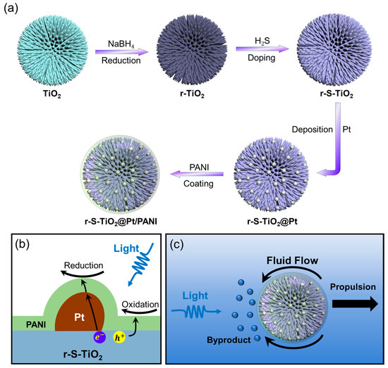
Figure 1.
(a) Illustration of the fabrication process of TiO2@Pt/PANI micromotor; (b) diagram showcasing the photoelectrochemical reaction pathway that occurs on the surface of the micromotor; (c) propulsion mechanism of the micromotor under visible light illumination.
Further improvement in the photoelectrochemical efficiency was accomplished by growing Pt nanoparticles on the surface of r-S-TiO2, which reduced the recombination efficiency of electron-hole pairs (Figure 1b). According to colloid and interface science theory, soft particles can maintain a certain ion tolerance in aqueous environments [32,33]. To enable the micromotors to operate in environments with relatively high ion concentrations, it was necessary to modify the surface of the micromotors with polymers that could endow them with ion tolerance as soft particles. In this study, the polymer coating on the surface not only acted as a barrier against ion penetration but also ensured the transport of photogenerated electron holes on the surface was not hindered. Consequently, conducting polyaniline (PANI) was selected as the coating polymer (Figure 1b). The working mechanism of r-S-TiO2@Pt/PANI micromotors is depicted in Figure 1c. Under visible light illumination, a redox reaction occurs on the illuminated side of the micromotors, leading to an asymmetric distribution of by-products on the micromotors, thereby driving the motion of micromotors.
3.2. Characterization of Surface Morphology and Composition of Micromotors
Upon comparing pure TiO2 microspheres (Figure 2a) and r-S-TiO2 microspheres (Figure 2b), it was evident that the dual doping process did not lead to surface collapse, and the needle-like surface morphology remains intact. Both samples have similar diameters of approximately 3 μm, with a nanoneedle diameter of approximately 20 nm. The substantial specific surface area guarantees the availability of sample redox reaction sites, thereby enhancing the catalytic activity. Notably, the magnified SEM images at the bottom of Figure 2a,b reveal that the TiO2 needle arrays are free of impurities, which could adversely impact photocatalytic activity. Following the thermal decomposition of Pt on r-S-TiO2 (Figure 2c), small particles with diameters of approximately 10 nm are distinctly visible on the partially exposed surface of r-S-TiO2@Pt (bottom of Figure 2c). It is worth noting that excessive deposition of Pt may not only diminish the light absorption capacity of r-S-TiO2 but also create a recombination center for electron-hole pairs, resulting in a significant reduction in photocatalytic efficiency [34]. Consequently, maintaining an appropriate Pt to r-S-TiO2 ratio is crucial for the effective fabrication of the self-propelled micromotor.
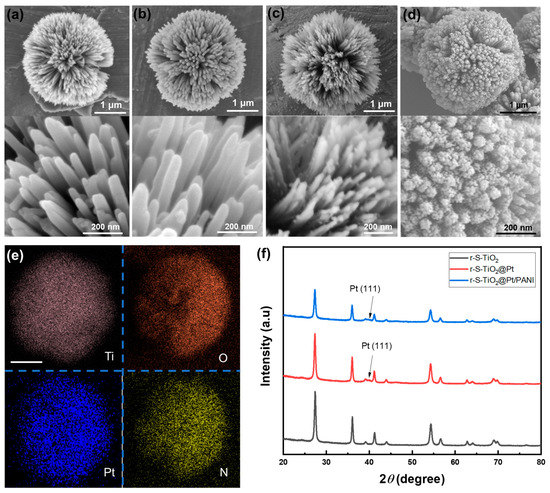
Figure 2.
SEM images of (a) pure TiO2; (b) r-S-TiO2; (c) r-S-TiO2@Pt; and (d) r-S-TiO2@Pt/PANI micromotors; (e) EDX mapping of Ti, O, Pt, and N in r-S-TiO2@Pt/PANI micromotor. The scale bar is 1 μm; (f) XRD analysis of r-S-TiO2 (black), r-S-TiO2@Pt (red), and r-S-TiO2@Pt/PANI (blue).
After coating PANI on r-S-TiO2@Pt, the surface of the micromotor is fully covered by PANI, resulting in a fluffy and porous surface (Figure 2d). To further confirm the Pt and PANI distribution on the micromotors, we conducted element mapping of Ti, O, Pt, and N of the micromotor by EDX, as shown in Figure 2e. The Pt and N elements align well with the shape and size of Ti and O, indicating the successful and uniform deposition of Pt and PANI on the micromotor surfaces. Figure 2f presents the XRD patterns. Pure TiO2 has previously been shown to exhibit a 100% rutile phase. After dual doping with oxygen vacancy and S, the phase of r-S-TiO2 was maintained as rutile (black curve), which was consistent with other reported findings. After the thermal deposition of Pt, the (111) plane of Pt was observed in both r-S-TiO2@Pt and r-S-TiO2@Pt/PANI samples (red and blue curves). However, the typical signal of PANI was not detected in the r-S-TiO2@Pt/PANI sample, possibly due to the amorphous structure of the PANI synthesized in this instance.
3.3. Characterization of Doping of TiO2
To demonstrate the successful doping of S into the TiO2 lattice, we first investigate the surfaces of pure TiO2, r-TiO2, and r-S-TiO2 using high-resolution transmission electron microscopy (HRTEM), as shown in Figure 3a–c. Prior to NaBH4 reduction, the surface of TiO2 appeared noticeably smooth, with the crystal faces of (110) exhibiting an interplanar spacing of 3.2 Å (Figure 3a). This observation further confirms the rutile phase of the as-fabricated TiO2. Following NaBH4 reduction, the surface of r-TiO2 became rough (Figure 3b). In Figure 3c, the presence of a core-shell structure is clearly evident after treating r-TiO2 with H2S gas. The core exhibits a crystal structure with a regular arrangement of atoms, while the shell displays a collapsed, disordered arrangement. This finding is consistent with the surface structure of other reported S-doped TiO2 materials [31]. Additionally, we captured a scanning transmission electron microscopy (STEM) image of a single r-S-TiO2 nanoneedle and conducted elemental mapping, as presented in Figure 3d. The distribution of titanium (blue) and oxygen (green) is in good agreement with the nanoneedle’s shape, while the presence of sulfur (yellow) is only faintly visible. We attribute this limited visibility to the low sulfur content, approximately 0.51 wt.%.
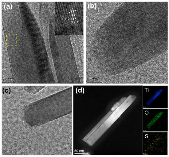
Figure 3.
HRTEM images of (a) pure-TiO2. The insert image is an enlarged view of the yellow dashed area. (b) r-TiO2, and (c) r-S-TiO2; (d) EDS of r-S-TiO2 nanoneedle.
The reduction of NaBH4 can generate oxygen vacancies, potentially leading to the formation of Ti3+ ions on the sample surface. Consequently, O2− ions can be adsorbed onto the surface of TiO2 [31]. Therefore, electron paramagnetic resonance (EPR) was conducted to further investigate the presence of Ti3+ states on the surface of r-S-TiO2. As depicted in Figure 4a, both r-TiO2 and r-S-TiO2 samples exhibit prominent signal peaks, while pure TiO2 shows negligible peaks. The peak intensity of r-TiO2 is higher than that of r-S-TiO2, primarily due to the incorporation of S into the TiO2 lattice, resulting in a reduced Ti3+ concentration. To further confirm the successful doping of S into r-TiO2, we performed an X-ray photoelectron spectroscopy (XPS) survey analysis of r-S-TiO2 (Figure 4b), revealing no obvious peaks other than those corresponding to O 1S, Ti 2p, and C 1s. This result confirms that no other impurity elements have been introduced. The peak intensity of Ti 2p1/2 (Figure 4c) and O 1s (Figure 4d) decreased as the reduction and S doping progressed, consistent with previous findings that suggest a decrease in peak intensity with a higher degree of reduction [35]. In Figure 4e, a broad S 2p signal ranging from 159.3 to 165.5 eV is observed in the r-S-TiO2 sample, with the peak located at approximately 162.3 eV. According to previous literature reports, S dopants are considered to substitute oxygen atoms in TiO2, indicating Ti-S bonding in the observed S 2p signal. In Figure 4f, the valence band XPS spectrum of r-S-TiO2 is compared with that of pure TiO2 and r-TiO2. While pure TiO2 and r-TiO2 exhibit a maximum energy edge of the valence band at approximately 2.07 eV, the valence band edge of r-S-TiO2 is shifted to approximately 1.5 eV, indicating that the valence band of r-S-TiO2 moves closer to the vacuum level at approximately 0.57 eV.
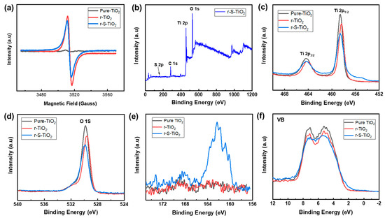
Figure 4.
(a) Electron paramagnetic resonance of pure-TiO2 (black), r-TiO2 (red), and r-S-TiO2 (blue); (b) low-resolution XPS survey spectra of r-S-TiO2. High-resolution XPS spectra of (c) Ti 2p, (d) O 1s, (e) S 2p, (f) VB XPS of pure-TiO2 (black), r-TiO2 (red), and r-S-TiO2 (blue).
3.4. Optical and Electronic Properties of Micromtors
The optical properties of r-S-TiO2 were characterized utilizing UV–vis DRS spectroscopy, as shown in Figure 5a. It is observed that the sample of r-S-TiO2 significantly enhances the visible light absorption compared to both TiO2 and r-TiO2. S-TiO2 exhibits only a slight increase in the light range from 400 to 500 nm. As previously mentioned, without reducing TiO2, it is difficult to incorporate elemental S into the TiO2, resulting in negligible improvement in the efficiency of visible light. These observations were consistent with the absorption curves reported in other literature for S-doped TiO2 [36,37,38,39]. Based on the UV–vis DRS spectra, a Tauc plot was constructed, allowing the calculation of the energy bandgap for r-S-TiO2 to be approximately 2.55 eV. In contrast, the energy bandgaps for pure TiO2 and r-TiO2 were approximately 3.05 and 2.96 eV, respectively. The reduced energy bandgap of r-S-TiO2 signifies its capacity to harness visible light, generate electron-hole pairs, and participate in redox reactions, thereby driving photoelectrochemical reactions.
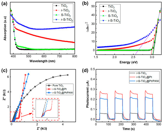
Figure 5.
(a) UV–vis DRS spectroscopy of pure-TiO2 (black), r-TiO2 (red), and r-S-TiO2 (blue); (b) Tauc plot of the three samples derived from (a), the solid lines that intersect the horizontal axis are the tangents to the respective curves; (c) EIS spectroscopy of three samples: pure TiO2, r-S-TiO2@Pt, and r-S-TiO2@Pt/PANI; (d) photocurrent of r-S-TiO2, r-S-TiO2@Pt, and r-S-TiO2@Pt/PANI.
After the application of PANI onto r-S-TiO2@Pt, the charge transfer resistance (Rct) of r-S-TiO2/Pt@PANI was measured using electrochemical impedance spectroscopy (EIS) and compared with those of r-S-TiO2 and r-S-TiO2@Pt, as shown in Figure 5c. The presence of Pt in r-S-TiO2@Pt and r-S-TiO2@Pt/PANI samples significantly reduced Rct in comparison to pure TiO2. Furthermore, the continuous deposition of PANI resulted in a further decrease in Rct of r-S-TiO2@Pt/PANI (approximately 407 Ω), which was 22.5% of that of r-S-TiO2@Pt. Notably, the slope of the curves for r-S-TiO2@Pt in the low-frequency region was slightly higher than that of r-S-TiO2@Pt/PANI. This effect was attributed to the hindering effect of the polymer on the diffusion of particles. To investigate the photocatalytic activity of micromotors under visible light illumination, we measured the photocurrent of r-S-TiO2, r-S-TiO2@Pt, and r-S-TiO2@Pt/PANI samples by using an electrochemical workstation at a visible light intensity of 1.6 W/cm2 (Figure 5d). After Pt deposition on micromotors, the photocurrent intensity increased by approximately 5.3 times compared to r-S-TiO2. However, the r-S-TiO2@Pt/PANI sample showed a decrease of almost 75.5 % relative to r-S-TiO2@Pt. We speculated that this was mainly due to the partial absorption of light by PANI, which weakened the absorption of light by TiO2.
3.5. Motion Behavior of Micromotors in Pure Water
We first characterized the motion behavior of r-S-TiO2@Pt/PANI micromotors in a pure water environment under visible light illumination (Video S1). The motion trajectories of the micromotors are captured and presented in Figure 6a during approximately 60 s of 1.6 W/cm2 light illumination. The negative phototactic behavior of the micromotors is demonstrated by their movement away from the light source, and their average velocity is calculated to be approximately 1.65 μm/s. It is widely recognized that UV photons possess higher energy compared to visible photons, thereby leading to a more efficient excitation of electron-hole pairs during photoelectrochemical reactions. In addition, although doped rutile has visible light catalytic activity, its catalytic activity under visible light is lower than that under UV. As a result, the velocities of r-S-TiO2@Pt/PANI micromotors under visible light were lower than those in our previous work, which were driven under UV light illumination. In Figure 6b, the obvious step change in velocity under the on/off states of light was plotted, which indicates that the directional motion of the micromotor was influenced by the photoelectrochemical reaction. To gain further insight into the working mechanism of the micromotors, we calculated the mean squared displacement (MSD) under various intensities of visible light (Figure 6c). The quadratic curves of MSD suggested the electrophoretic/electroosmotic motion of the micromotors. The present micromotor has an isotropic structure; thus, when unidirectional light is irradiated on its surface, only the illuminated side produces photoelectrochemical reactions and generates by-products, which leads to an asymmetric distribution of by-products between the light-facing and the back-light side. Therefore, the by-product provides propulsion force for micromotors’ directional movement mainly through electrophoretic/electroosmotic effects [24,40]. The velocity of micromotors vs. light intensity was also plotted in Figure 6d. As the incident light intensity increased, the velocities were noticeably enhanced, indicating the direct influence of light intensity on the micromotors’ velocity. Note that the velocity of micromotors is not obvious to see when lower visible light intensity is applied. To obtain effective motion behavior, we chose the value of light intensity to be 1.6 W/cm2, which is comparable to those micromotors with visible light photocatalytic activity [40,41].
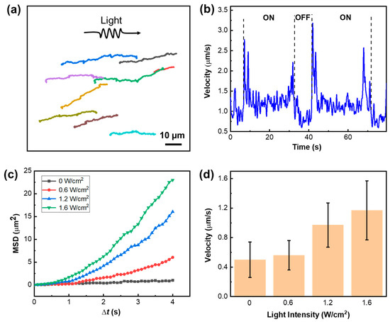
Figure 6.
(a) Motion trajectory of r-S-TiO2@Pt/PANI micromotors under 1.6 W/cm2 visible light (>400 nm) illumination, note that lines of different colors represent the trajectory of different micromotors. (b) velocities of r-S-TiO2 micromotors in ON/OFF states of visible light; (c) the MSD curves of micromotors under different light intensities; (d) histogram of micromotor velocities under different light intensities.
3.6. Motion of Micromotors in Different Concentrations of NaCl Solutions
The motion of light-driven micromotors is significantly influenced by the salinity in the solution. As the concentration increases, the speed of the micromotors tends to decrease, while their trajectory becomes more erratic [22,42]. When polyelectrolytes with ion-permeable surface layers are assembled on a colloidal particle, the electrical diffuse double layer formed between the particle and electrolyte solution exists not only at their interface but also within the surface charge layer of polyelectrolytes. This plays a vital role in maintaining the non-zero electrophoretic mobility of micromotors at higher salinity levels [42]. After coating PANI on r-S-TiO2@Pt, the resulting micromotors demonstrated favorable ion-tolerant characteristics. In Figure 7a, the moving trajectory of micromotors between r-S-TiO2@Pt and r-S-TiO2@Pt/PANI was compared in NaCl solutions of different concentrations, ranging from 0 to 10 mM. As the ion concentration increased, the motion displacement of the r-S-TiO2@Pt micromotor decreased significantly and eventually reached zero at an ion concentration of 10 mM due to the quenching of the electric double layer by ions. However, the r-S-TiO2@Pt/PANI micromotor still retained 29.7% of its displacement in 10 mM NaCl solution compared to that in 0 mM NaCl solution.
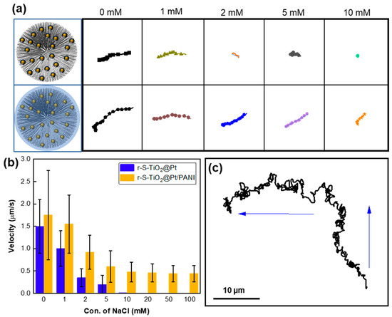
Figure 7.
(a) Motion trajectory of r-S-TiO2 micromotors at different NaCl concentrations relative to r-S-TiO2; (b) velocities of micromotors vs. different concentrations of NaCl; (c) trajectory of micromotor under different light illumination direction (blue arrow).
We also calculated the velocities at increasing ion concentrations (Figure 7b), where the velocity of the r-S-TiO2@Pt micromotor quickly decreased from 1.5 μm/s to 0 when the ion concentration reached 10 mM. In contrast, the velocity of the r-S-TiO2@Pt/PANI micromotor remained at 0.47 μm/s even in 0.1 M NaCl solution. Thus, the as-prepared micromotors exhibited a significant improvement in ion tolerance in NaCl solutions as high as 0.1 M. It is worth noting that r-S-TiO2@Pt micromotors exhibited positive phototaxis in motion while r-S-TiO2@Pt/PANI micromotors exhibited negative phototaxis behavior. The coating of PANI, which contains abundant amino groups, changes the zeta potential of the micromotor, which is a core factor influencing the motion behaviors of LEMs as our previous work has demonstrated [24]. Furthermore, we investigated the controllability of micromotors, as shown in Figure 7c. The trajectory of the micromotors was recorded as the light direction changed within two minutes of illumination. The micromotor maintained negative phototaxis motion behavior even at high ion concentrations, proving the effective control of micromotors by illumination direction.
4. Summary
In this work, we successfully tuned the bandgap of rutile TiO2 from 3.0 to 2.55 eV through oxygen vacancy and sulfur doping, making it responsive to visible light. After modifying its surface with Pt and PANI, the as-prepared r-S-TiO2@Pt/PANI micromotors displayed distinct negative phototactic motion behavior with a velocity of 1.65 μm/s under 1.6 W/cm2 visible light illumination in a pure water environment. More importantly, the polyelectrolyte PANI on the surface significantly enhanced its ion tolerance, enabling it to swim in a 0.1 M NaCl solution. Designing LEMs to adapt to high-salinity environments is challenging. The velocity of our TiO2-based micromotors can still be improved via many approaches. Introducing metal (e.g., Fe, Co, Ni, Ag) or non-metal (e.g., N, C, F) dopants into the TiO2 lattice can modify its electronic structure, reduce the bandgap, and enhance visible light absorption. Creating heterojunctions between TiO2 and other semiconductors (e.g., ZnO, CdS, WO3, BiVO4) can facilitate charge separation and reduce the recombination rate of photogenerated electron-hole pairs, thereby improving photocatalytic performance. Surface modification with noble metals (e.g., Au, Pt, Pd) or co-catalysts (e.g., graphene, carbon nanotubes) onto the surface of TiO2 can serve as electron sinks or provide additional active sites, promoting charge separation. Tailoring the morphology (e.g., nanoparticles, nanorods, nanosheets, nanofibers) and crystal structure (e.g., anatase, rutile, brookite) of TiO2 can influence its surface area, crystallinity, and light absorption properties. Recently, it has been found that incorporating plasmonic nanostructures (e.g., Au, Ag nanoparticles) into TiO2 can enhance its light absorption through the generation of localized surface plasmon resonance and improve photocatalytic activity under visible light. By exploring these strategies, the photocatalytic activity of electrophoretic TiO2-based micromotors demonstrates significant potential for a variety of applications, including water and air purification, energy conversion, and environmental remediation.
Supplementary Materials
The following supporting information can be downloaded at: https://www.mdpi.com/article/10.3390/nano13121827/s1; Video S1: r-S-TiO2@Pt/PANI micromotors swimming in fuel-free environment.
Author Contributions
Conceptualization, H.J. and C.H.; methodology, H.J. and X.H.; investigation, H.J. and M.Y.; supervision, C.H.; writing—original draft, H.J., X.H., M.Y. and C.H.; writing—review and editing, H.J. and C.H. All authors have read and agreed to the published version of the manuscript.
Funding
This work is supported by the Shenzhen Science and Technology Program (Grant No. JCYJ20190809144013494), and the Science and Technology Program of Guangdong (Grant No. 2021A1515011813). This work is partly supported by the Science, Technology, and Innovation Commission of Shenzhen Municipality under grant no. ZDSYS20200811143601004, and in part by the Southern Marine Science and Engineering Guangdong Laboratory (Guangzhou) and Stable Support Plan Program of Shenzhen Natural Science Fund under Grant 20220815104331001.
Institutional Review Board Statement
Not applicable.
Informed Consent Statement
Not applicable.
Data Availability Statement
Data sharing is not applicable to this article.
Acknowledgments
The authors acknowledge the assistance of SUSTech Core Research Facilities and the support from Wenjun Lu at Southern University of Science and Technology for the HRTEM characterization of the materials.
Conflicts of Interest
The authors declare no conflict of interest.
References
- Singh, V.V.; Wang, J. Nano/micromotors for security/defense applications. A review. Nanoscale 2015, 7, 19377–19389. [Google Scholar] [CrossRef]
- Guix, M.; Mayorga-Martinez, C.C.; Merkoçi, A. Nano/micromotors in (bio) chemical science applications. Chem. Rev. 2014, 114, 6285–6322. [Google Scholar] [CrossRef] [PubMed]
- Sonntag, L.; Simmchen, J.; Magdanz, V. Nano-and micromotors designed for cancer therapy. Molecules 2019, 24, 3410. [Google Scholar] [CrossRef]
- Fernández-Medina, M.; Ramos-Docampo, M.A.; Hovorka, O.; Salgueiriño, V.; Städler, B. Recent advances in nano-and micromotors. Adv. Funct. Mater. 2020, 30, 1908283. [Google Scholar] [CrossRef]
- Hu, W.; Ma, Y.; Zhan, Z.; Hussain, D.; Hu, C. Robotic intracellular electrochemical sensing for adherent cells. Cyborg Bionic Syst. 2022, 2022, 9763420. [Google Scholar] [CrossRef] [PubMed]
- Wang, H.; Kan, J.; Zhang, X.; Gu, C.; Yang, Z. Pt/CNT micro-nanorobots driven by glucose catalytic decomposition. Cyborg Bionic Syst. 2021, 2021, 9876064. [Google Scholar] [CrossRef]
- Chen, C.; Karshalev, E.; Guan, J.; Wang, J. Magnesium-based micromotors: Water-powered propulsion, multifunctionality, and biomedical and environmental applications. Small 2018, 14, 1704252. [Google Scholar] [CrossRef]
- Lin, X.; Xu, B.; Zhu, H.; Liu, J.; Solovev, A.; Mei, Y. Requirement and development of hydrogel micromotors towards biomedical applications. Research 2020, 2020, 7659749. [Google Scholar] [CrossRef]
- Xu, L.; Mou, F.; Gong, H.; Luo, M.; Guan, J. Light-driven micro/nanomotors: From fundamentals to applications. Chem. Soc. Rev. 2017, 46, 6905–6926. [Google Scholar] [CrossRef]
- Huang, C.; Lai, Z.; Wu, X.; Xu, T. Multimodal locomotion and cargo transportation of magnetically actuated quadruped soft microrobots. Cyborg Bionic Syst. 2022, 2022, 0004. [Google Scholar] [CrossRef]
- Kochergin, Y.S.; Villa, K.; Nemeskalova, A.; Kuchař, M.; Pumera, M. Hybrid inorganic-organic visible-light-driven microrobots based on donor-acceptor organic polymer for degradation of toxic psychoactive substances. ACS Nano 2021, 15, 18458–18468. [Google Scholar] [CrossRef] [PubMed]
- Mou, F.; Kong, L.; Chen, C.; Chen, Z.; Xu, L.; Guan, J. Light-controlled propulsion, aggregation and separation of water-fuelled TiO2/Pt Janus submicromotors and their “on-the-fly” photocatalytic activities. Nanoscale 2016, 8, 4976–4983. [Google Scholar] [CrossRef] [PubMed]
- Pourrahimi, A.M.; Villa, K.; Manzanares Palenzuela, C.L.; Ying, Y.; Sofer, Z.; Pumera, M. Catalytic and light-driven Zno/Pt Janus nano/micromotors: Switching of motion mechanism via interface roughness and defect tailoring at the nanoscale. Adv. Funct. Mater. 2019, 29, 1808678. [Google Scholar] [CrossRef]
- Dong, R.; Hu, Y.; Wu, Y.; Gao, W.; Ren, B.; Wang, Q.; Cai, Y. Visible-light-driven BiOI-based Janus micromotor in pure water. J. Am. Chem. Soc. 2017, 139, 1722–1725. [Google Scholar] [CrossRef] [PubMed]
- Wang, J.; Wu, H.; Liu, X.; Liang, Q.; Bi, Z.; Wang, Z.; Cai, Y.; Dong, R. Carbon-dot-induced acceleration of light-driven micromotors with inherent fluorescence. Adv. Intell. Syst. 2020, 2, 1900159. [Google Scholar] [CrossRef]
- Wolff, N.; Ciobanu, V.; Enachi, M.; Kamp, M.; Braniste, T.; Duppel, V.; Shree, S.; Raevschi, S.; Medina-Sánchez, M.; Adelung, R. Advanced hybrid GaN/ZnO nanoarchitectured microtubes for fluorescent micromotors driven by UV light. Small 2020, 16, 1905141. [Google Scholar] [CrossRef]
- Kochergin, Y.S.; Villa, K.; Novotný, F.; Plutnar, J.; Bojdys, M.J.; Pumera, M. Multifunctional visible-light powered micromotors based on semiconducting sulfur-and nitrogen-containing donor-acceptor polymer. Adv. Funct. Mater. 2020, 30, 2002701. [Google Scholar] [CrossRef]
- Maria Hormigos, R.; Jurado Sanchez, B.; Escarpa, A. Multi-light-responsive quantum dot sensitized hybrid micromotors with dual-mode propulsion. Angew. Chem. Int. Ed. Engl. 2019, 58, 3128–3132. [Google Scholar] [CrossRef]
- Jang, B.; Hong, A.; Kang, H.E.; Alcantara, C.; Charreyron, S.; Mushtaq, F.; Pellicer, E.; Buchel, R.; Sort, J.; Lee, S.S. Multiwavelength light-responsive Au/B-TiO2 Janus micromotors. ACS Nano 2017, 11, 6146–6154. [Google Scholar] [CrossRef]
- Zheng, J.; Dai, B.; Wang, J.; Xiong, Z.; Yang, Y.; Liu, J.; Zhan, X.; Wan, Z.; Tang, J. Orthogonal navigation of multiple visible-light-driven artificial microswimmers. Nat. Commun. 2017, 8, 1438. [Google Scholar] [CrossRef]
- Wang, J.; Xiong, Z.; Zheng, J.; Zhan, X.; Tang, J. Light-driven micro/nanomotor for promising biomedical tools: Principle, challenge, and prospect. Acc. Chem. Res. 2018, 51, 1957–1965. [Google Scholar] [CrossRef] [PubMed]
- Zhan, X.; Wang, J.; Xiong, Z.; Zhang, X.; Zhou, Y.; Zheng, J.; Chen, J.; Feng, S.-P.; Tang, J. Enhanced ion tolerance of electrokinetic locomotion in polyelectrolyte-coated microswimmer. Nat. Commun. 2019, 10, 3921. [Google Scholar] [CrossRef] [PubMed]
- Sridhar, V.; Podjaski, F.; Alapan, Y.; Kröger, J.; Grunenberg, L.; Kishore, V.; Lotsch, B.V.; Sitti, M. Light-driven carbon nitride microswimmers with propulsion in biological and ionic media and responsive on-demand drug delivery. Sci. Robot. 2022, 7, eabm1421. [Google Scholar] [CrossRef] [PubMed]
- Jiang, H.; He, X.; Ma, Y.; Fu, B.; Xu, X.; Subramanian, B.; Hu, C. Isotropic hedgehog-shaped-TiO2/functional-multiwall-carbon-nanotube micromotors with phototactic motility in fuel-free environments. ACS Appl. Mater. Interfaces 2021, 13, 5406–5417. [Google Scholar] [CrossRef] [PubMed]
- Huang, M.; Shao, Y.; Sun, X.; Chen, H.; Liu, B.; Dong, S. Alternate assemblies of platinum nanoparticles and metalloporphyrins as tunable electrocatalysts for dioxygen reduction. Langmuir 2005, 21, 323–329. [Google Scholar] [CrossRef]
- Safe, A.M.; Nikfarjam, A.; Hajghassem, H. UV enhanced ammonia gas sensing properties of PANI/TiO2 core-shell nanofibers. Sens. Actuators B Chem. 2019, 298, 126906. [Google Scholar] [CrossRef]
- Tariq, F.; Hussain, R.; Noreen, Z.; Javed, A.; Shah, A.; Mahmood, A.; Sajjad, M.; Bokhari, H.; ur Rahman, S. Enhanced antibacterial activity of visible light activated sulfur-doped TiO2 nanoparticles against Vibrio cholerae. Mater. Sci. Semicond. Process. 2022, 147, 106731. [Google Scholar] [CrossRef]
- Tian, H.; Ma, J.; Li, K.; Li, J. Hydrothermal synthesis of S-doped TiO2 nanoparticles and their photocatalytic ability for degradation of methyl orange. Ceram. Int. 2009, 35, 1289–1292. [Google Scholar] [CrossRef]
- Ho, W.; Jimmy, C.Y.; Lee, S. Low-temperature hydrothermal synthesis of S-doped TiO2 with visible light photocatalytic activity. J. Solid State Chem. 2006, 179, 1171–1176. [Google Scholar] [CrossRef]
- Fang, W.; Xing, M.; Zhang, J. A new approach to prepare Ti3+ self-doped TiO2 via NaBH4 reduction and hydrochloric acid treatment. Appl. Catal. B 2014, 160, 240–246. [Google Scholar] [CrossRef]
- Chongyin, Y.; Zhou, W.; Tianquan, L.; Hao, Y.; Xujie, L.; Dongyun, W.; Tao, X.; Chong, Z.; Jianhua, L.; Fuqiang, H. Core-shell nanostructured “black” rutile titania as excellent catalyst for hydrogen production enhanced by sulfur doping. J. Am. Chem. Soc. 2013, 135, 17831–17838. [Google Scholar]
- Ohshima, H. Electrical phenomena in a suspension of soft particles. Soft Matter 2012, 8, 3511–3514. [Google Scholar] [CrossRef]
- Ohshima, H. Theory of electrostatics and electrokinetics of soft particles. Sci. Technol. Adv. Mater. 2009, 10, 063001. [Google Scholar] [CrossRef] [PubMed]
- Wang, Y.; Zhu, Y.; Zhao, X.; Yang, X.; Li, X.; Chen, Z.; Yang, L.; Zhu, L.; Gao, T.; Sha, Z. Improving photocatalytic rhodamine B degrading activity with Pt quantum dots on TiO2 nanotube arrays. Surf. Coat. Technol. 2015, 281, 89–97. [Google Scholar] [CrossRef]
- Foo, C.; Li, Y.; Lebedev, K.; Chen, T.; Day, S.; Tang, C.; Tang, S.C.E. Characterisation of oxygen defects and nitrogen impurities in TiO2 photocatalysts using varible-temperature X-ray powder diffraction. Nat. Commun. 2021, 12, 661. [Google Scholar] [CrossRef]
- Piątkowska, A.; Janus, M.; Szymański, K.; Mozia, S. C-, N-and S-doped TiO2 photocatalysts: A review. Catalysts 2021, 11, 144. [Google Scholar] [CrossRef]
- Tang, X.; Li, D. Sulfur-doped highly ordered TiO2 nanotubular arrays with visible light response. J. Phys. Chem. C 2008, 112, 5405–5409. [Google Scholar] [CrossRef]
- Chen, X.; Burda, C. The electronic origin of the visible-light absorption properties of C-, N-and S-doped TiO2 nanomaterials. J. Am. Chem. Soc. 2008, 130, 5018–5019. [Google Scholar] [CrossRef]
- Ohno, T.; Akiyoshi, M.; Umebayashi, T.; Asai, K.; Mitsui, T.; Matsumura, M. Preparation of S-doped TiO2 photocatalysts and their photocatalytic activities under visible light. Appl. Catal. A-Gen. 2004, 265, 115–121. [Google Scholar] [CrossRef]
- Duan, W.; Liu, R.; Sen, A. Transition between collective behaviors of micromotors in response to different stimuli. J. Am. Chem. Soc. 2013, 135, 1280–1283. [Google Scholar] [CrossRef]
- Villa, K.; Novotny, F.; Zelenka, J.; Browne, M.P.; Ruml, T.; Pumera, M. Visible-light-driven single-component BiVO4 micromotors with the autonomous ability for capturing microorganisms. ACS Nano 2019, 13, 8135–8145. [Google Scholar] [CrossRef] [PubMed]
- Ashrafizadeh, S.N.; Seifollahi, Z.; Ganjizade, A.; Sadeghi, A. Electrophoresis of spherical soft particles in electrolyte solutions: A review. Electrophoresis 2020, 41, 81–103. [Google Scholar] [CrossRef]
Disclaimer/Publisher’s Note: The statements, opinions and data contained in all publications are solely those of the individual author(s) and contributor(s) and not of MDPI and/or the editor(s). MDPI and/or the editor(s) disclaim responsibility for any injury to people or property resulting from any ideas, methods, instructions or products referred to in the content. |
© 2023 by the authors. Licensee MDPI, Basel, Switzerland. This article is an open access article distributed under the terms and conditions of the Creative Commons Attribution (CC BY) license (https://creativecommons.org/licenses/by/4.0/).