
Discharge Enhancement in a Triple-Pipe Heat Exchanger Filled with Phase Change Material


 , and
, and 
Abstract
:1. Introduction
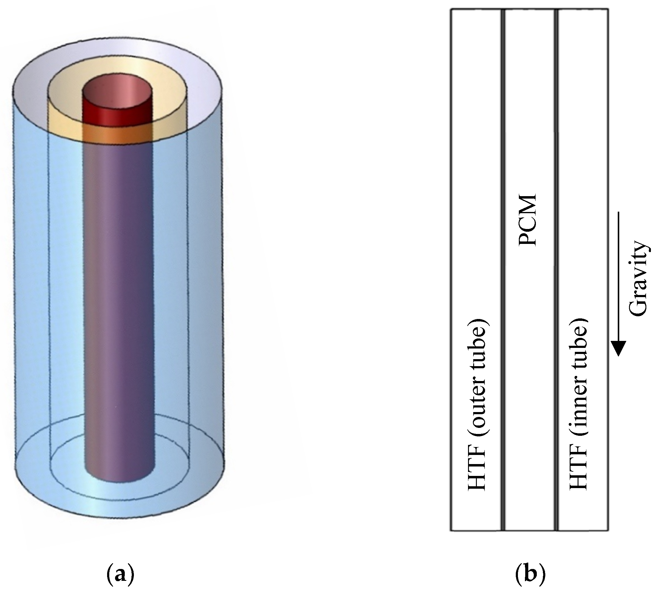
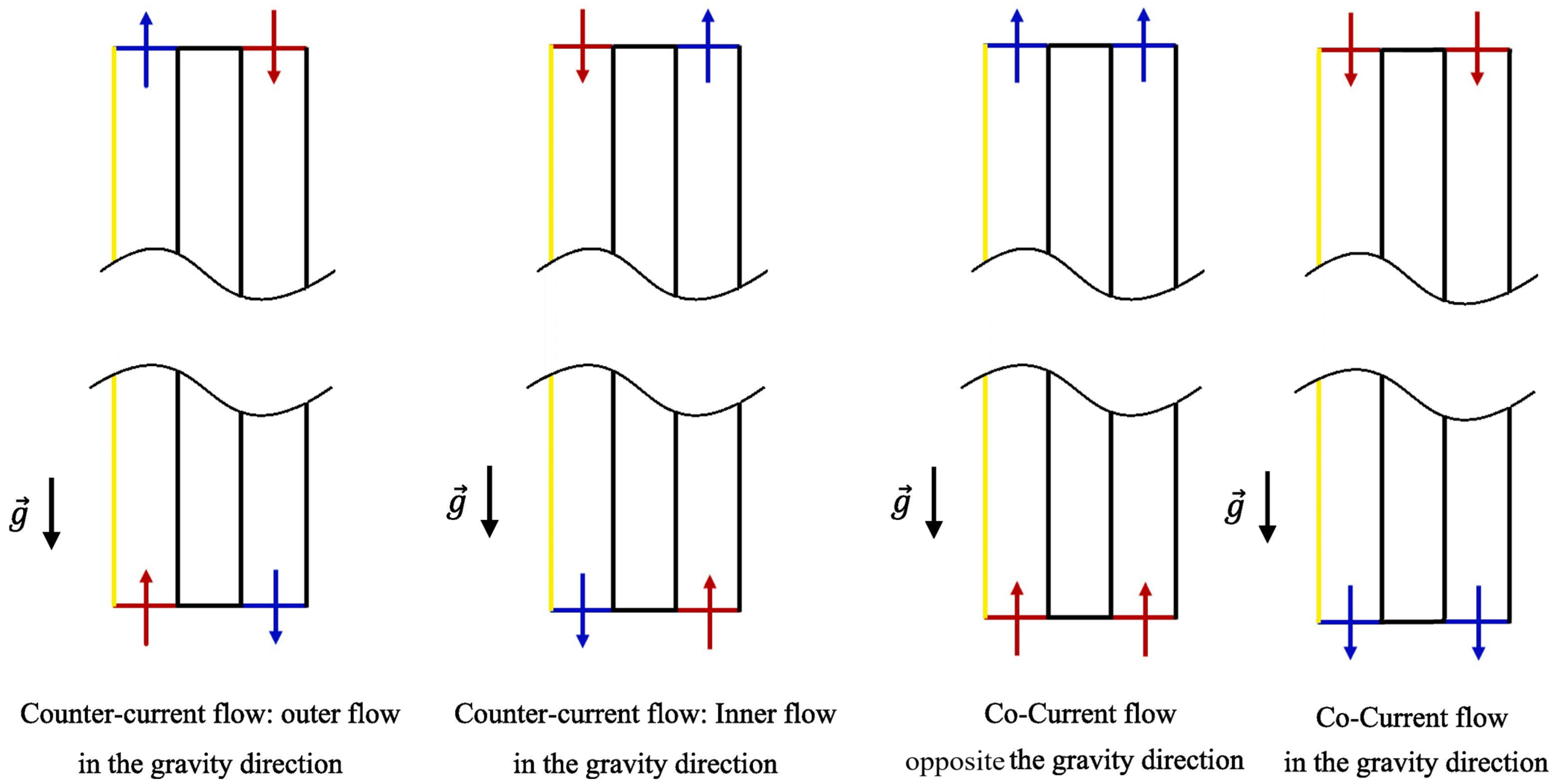
2. Problem Description
- co-current (both similar gravity): the flow direction in the inner and outer tubes are in the gravity direction;
- co-current (both opposite gravity): the flow direction in inner and outer tubes are opposite to the gravity direction;
- counter-current (inner similar gravity): the flow direction in the inner tube is the same as gravity;
- counter-current (outer similar gravity): the flow direction in the outer tube is the same as gravity.
3. Mathematical Formulation
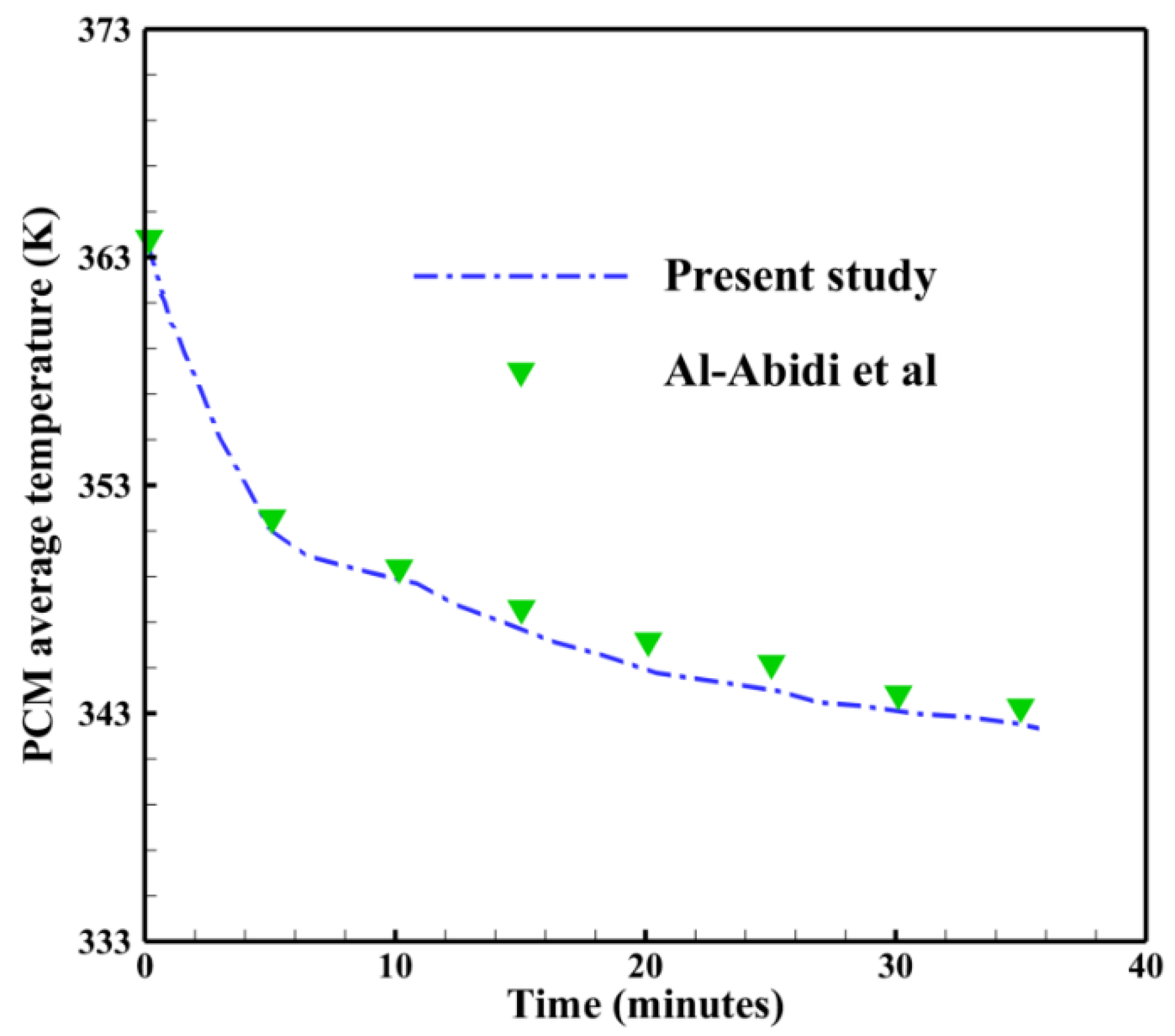
4. Numerical Description
5. Results and Discussion
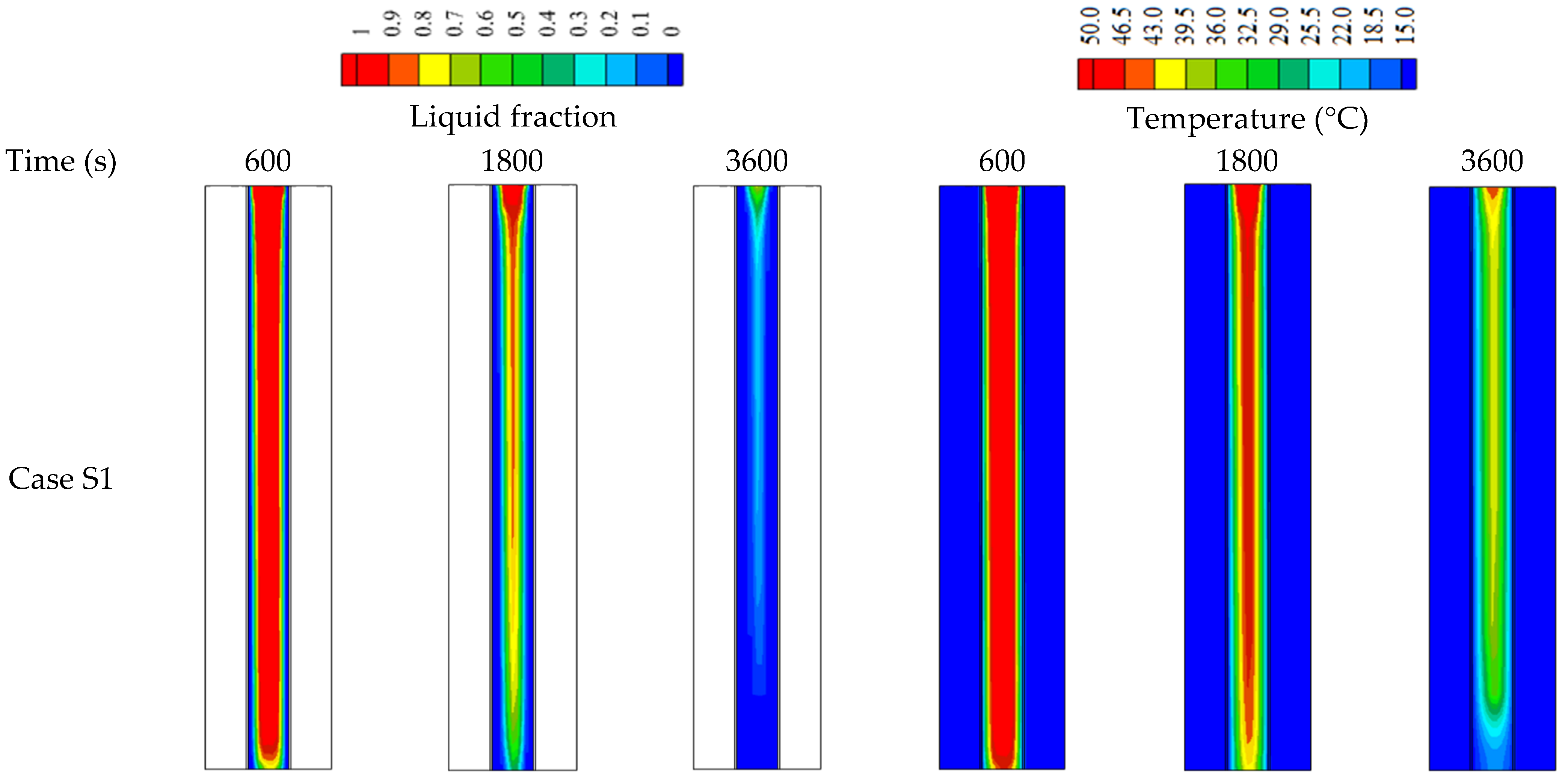
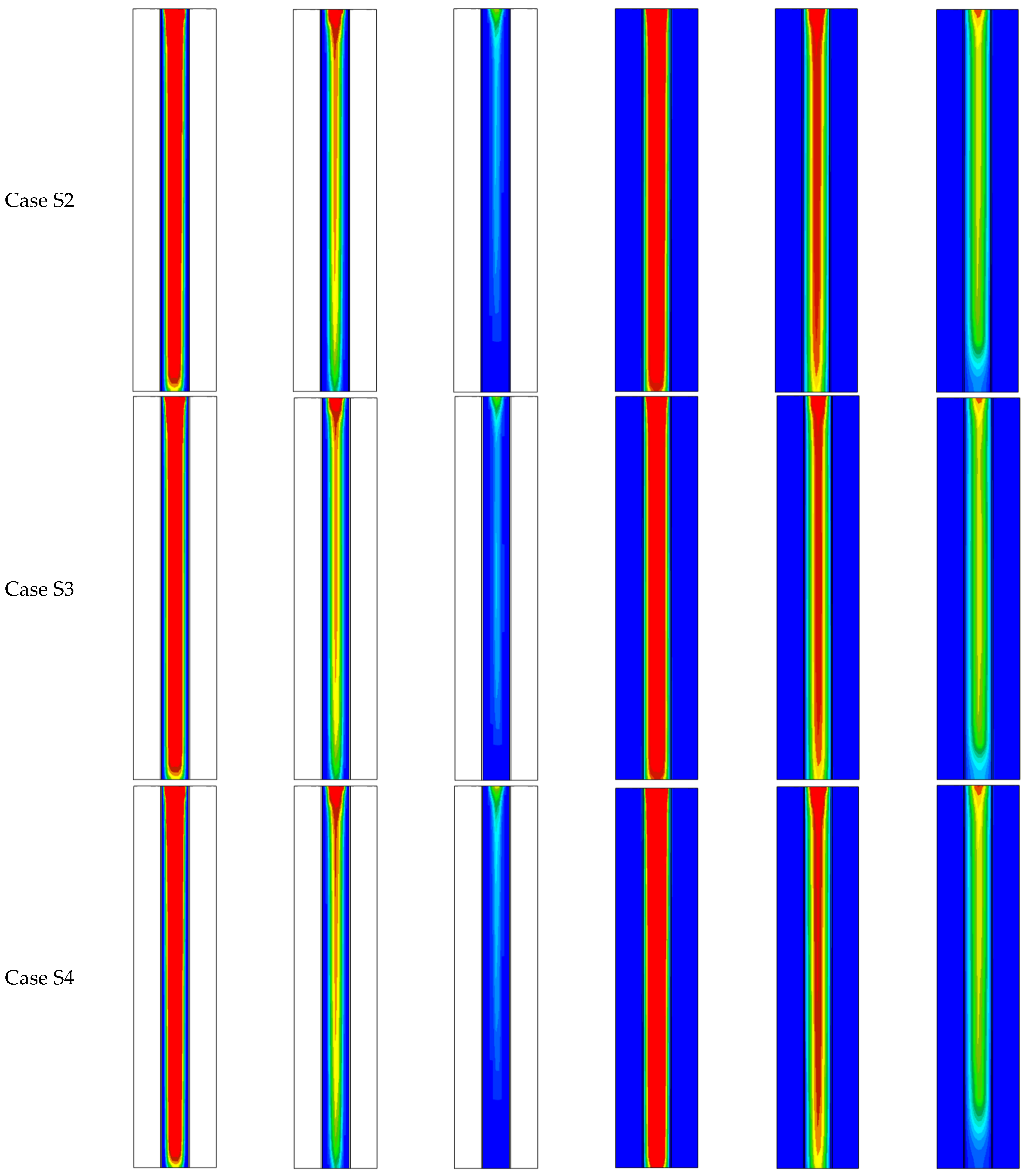
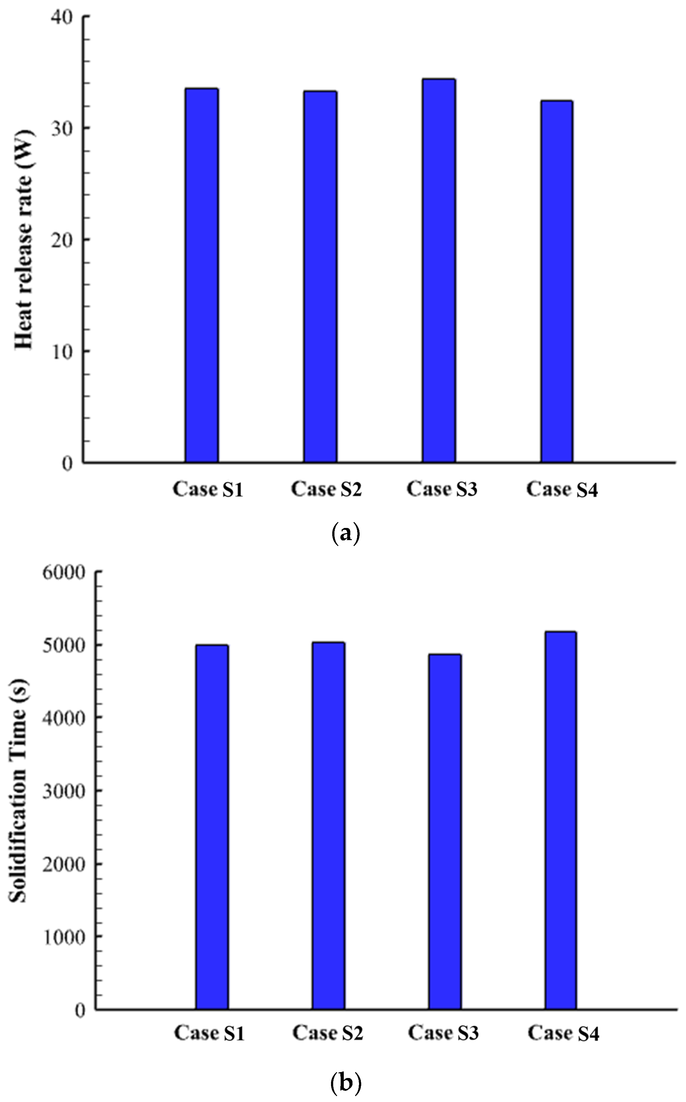
5.1. The Effect of the HTF Direction
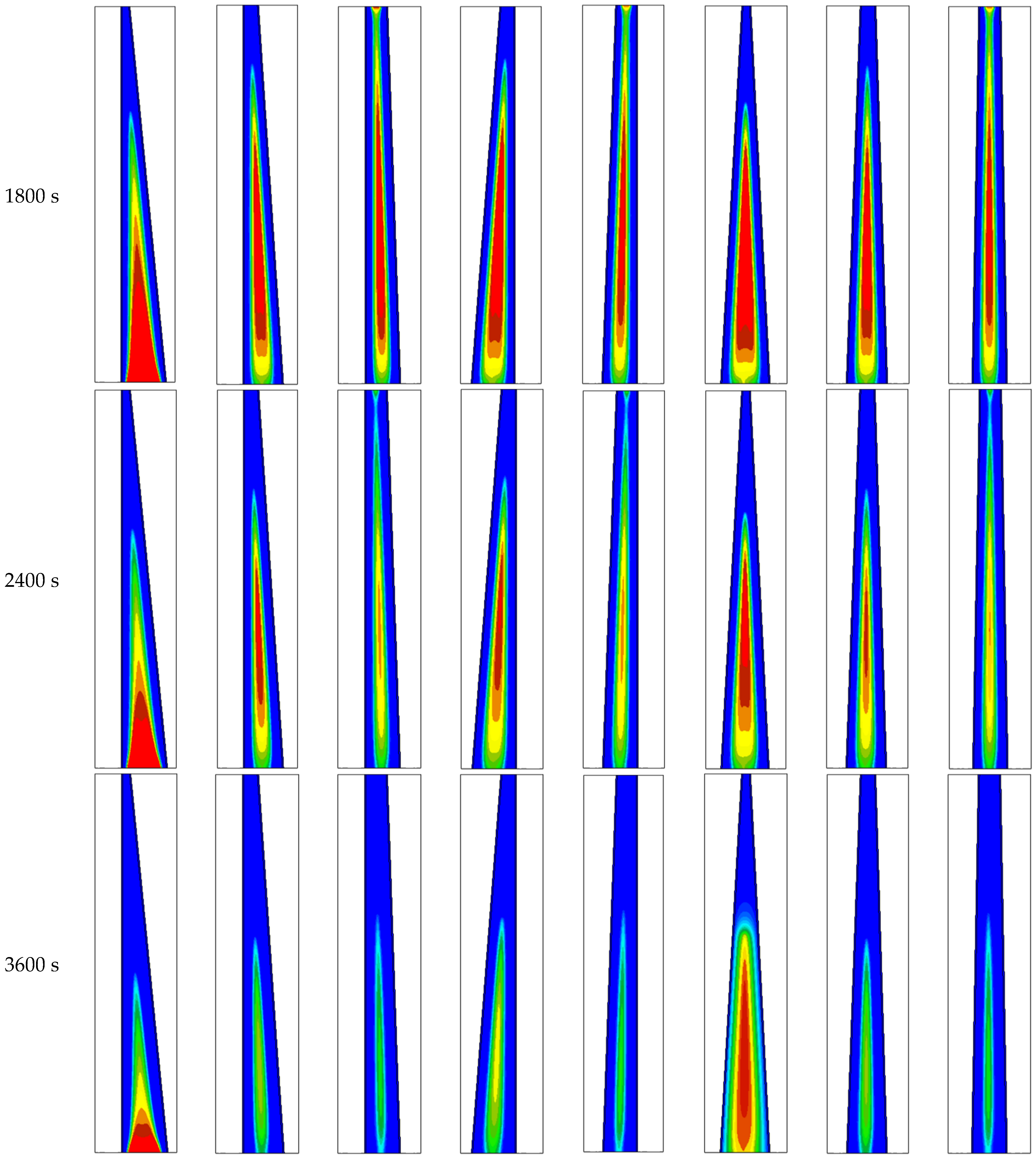
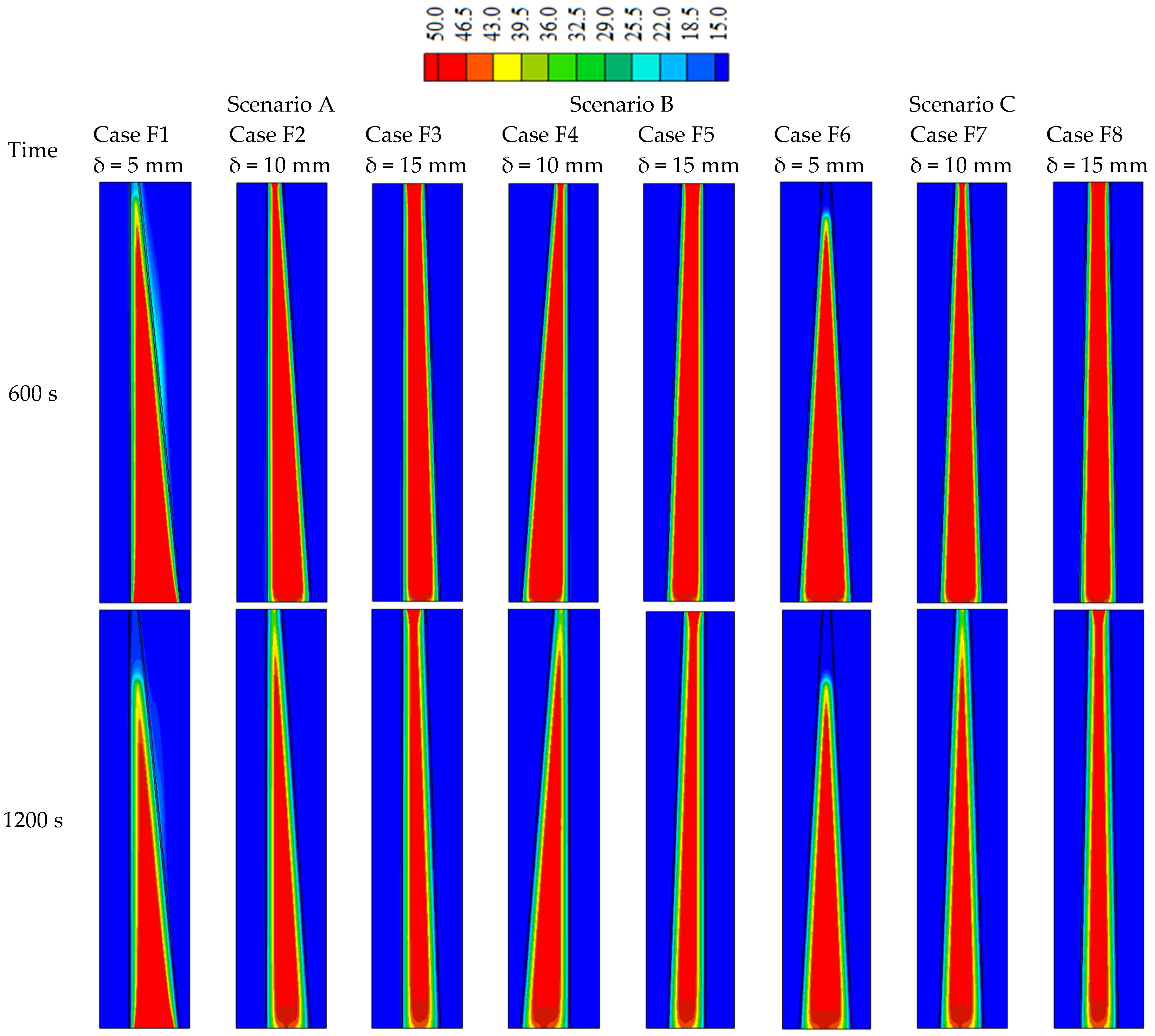
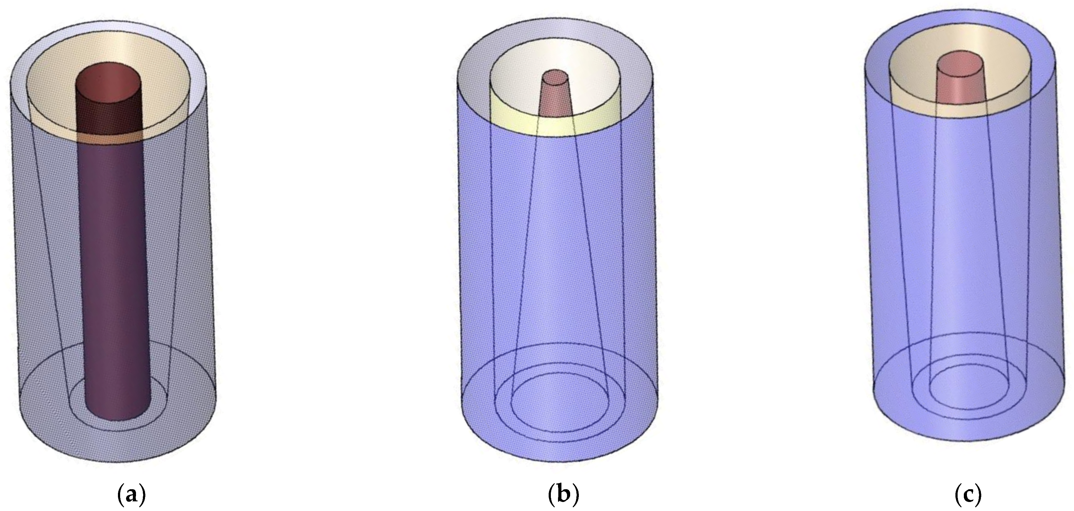
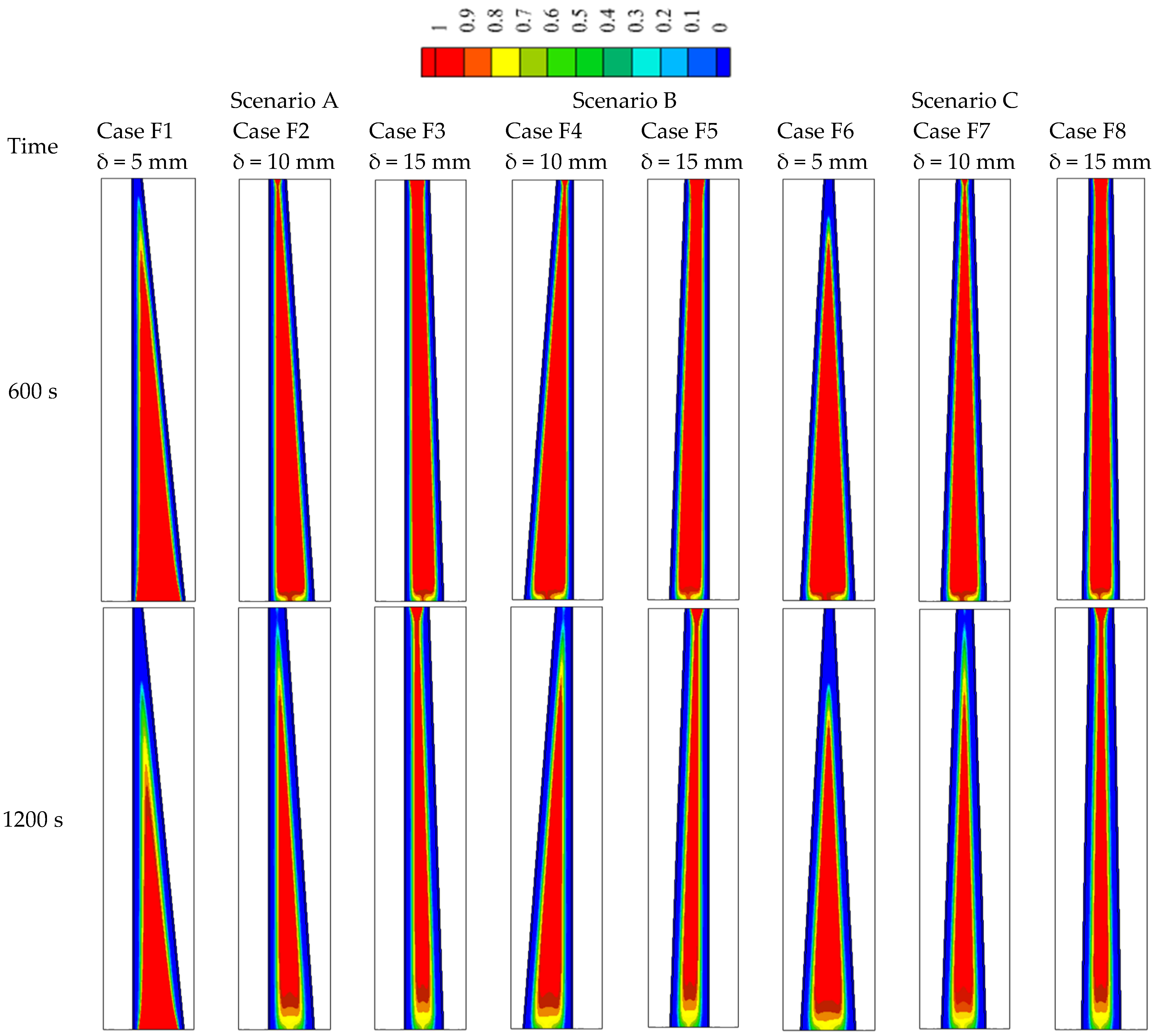
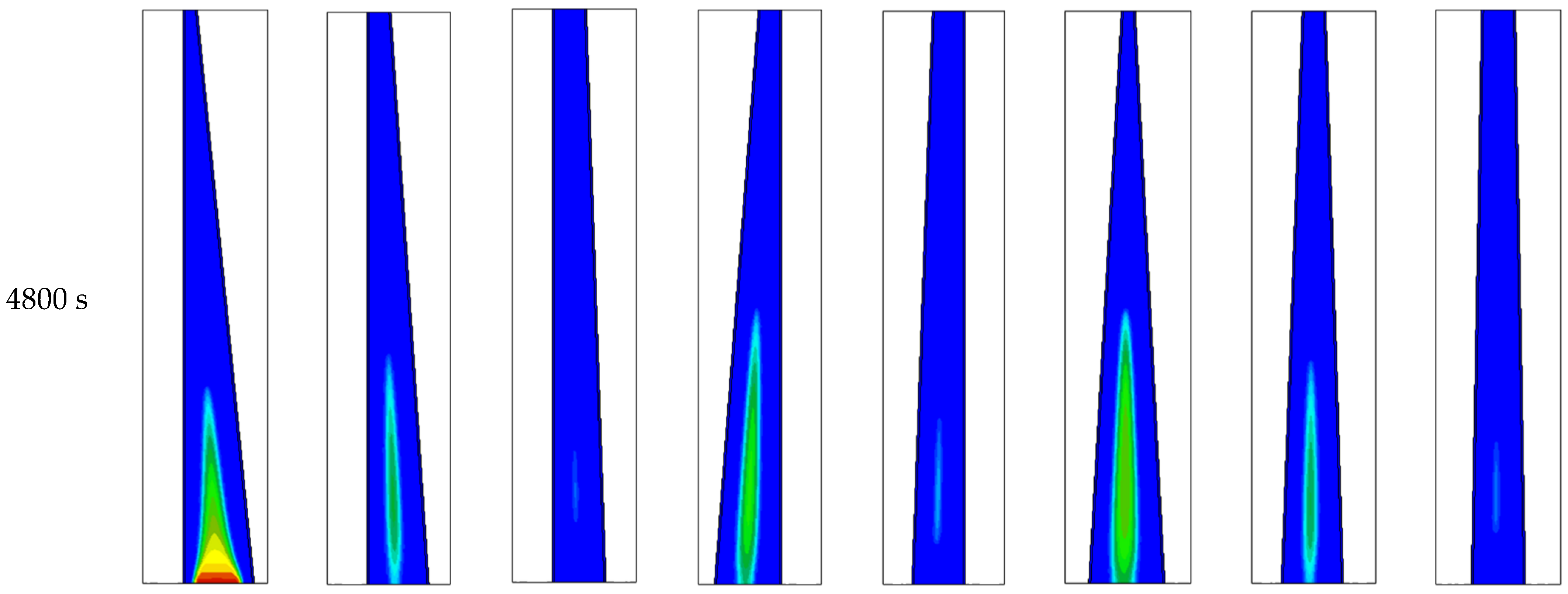
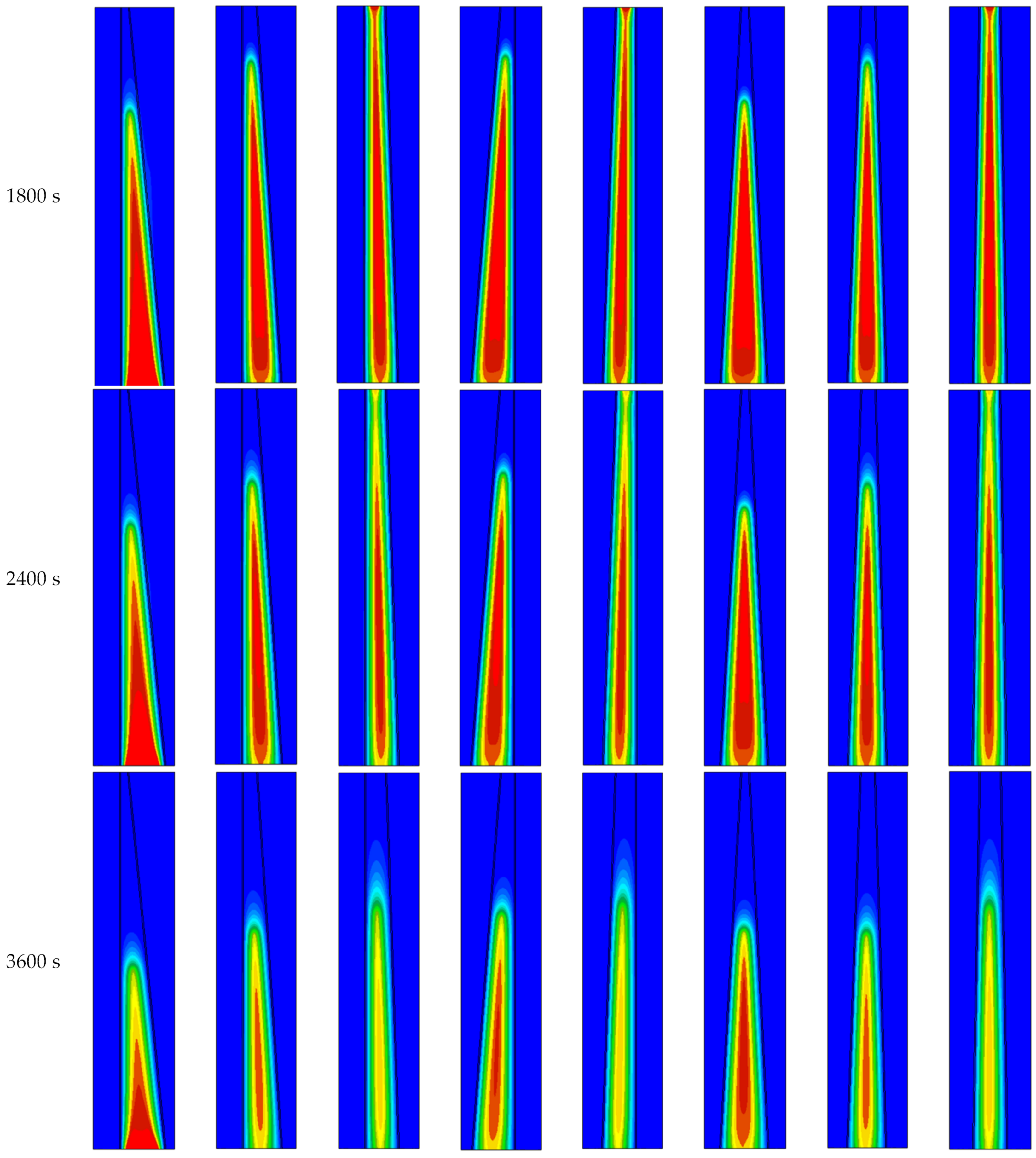
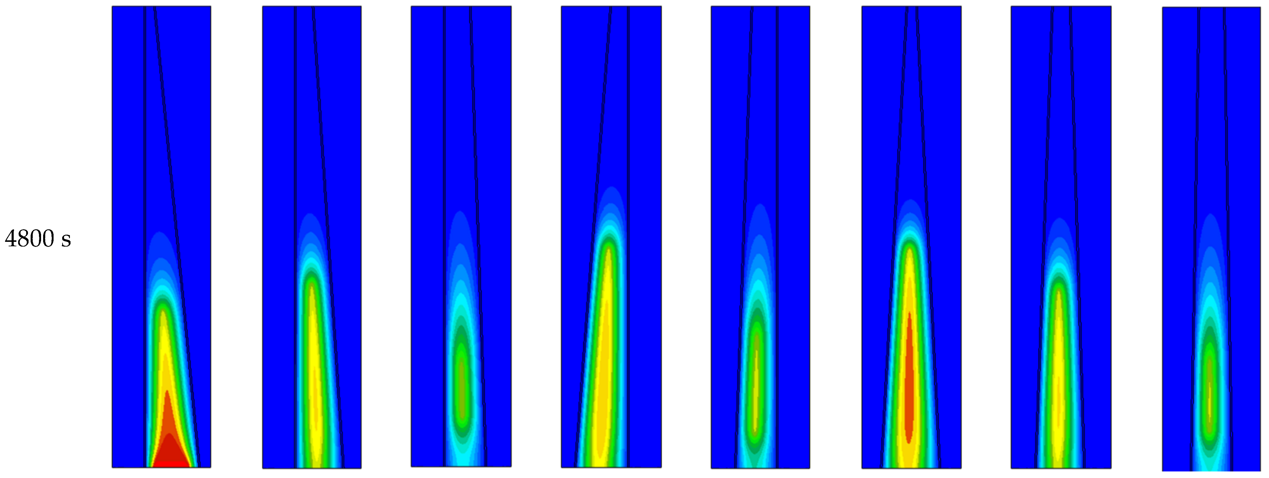
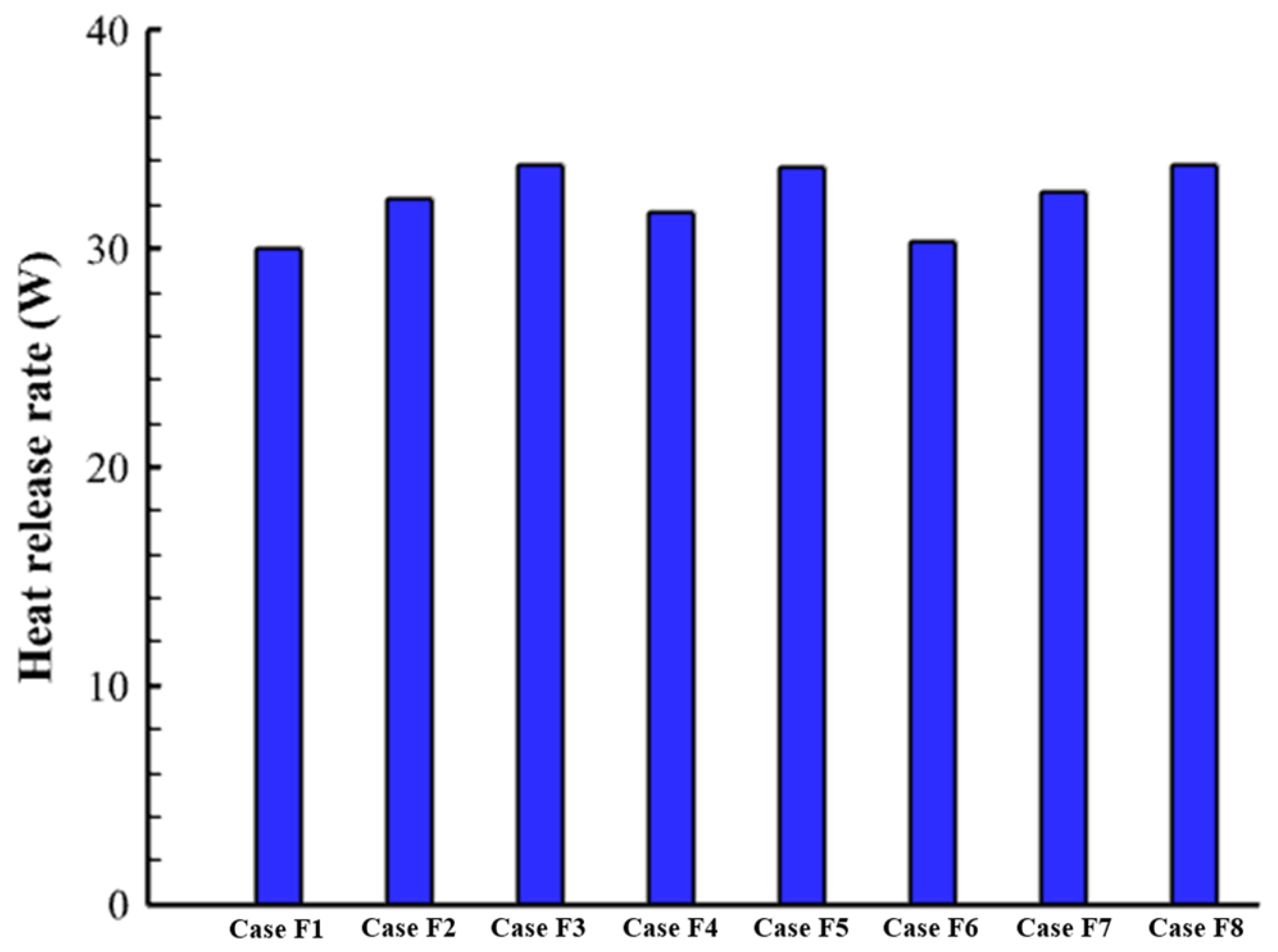
5.2. Effect of the PCM Container Shapes
6. Conclusions
Author Contributions
Funding
Informed Consent Statement
Data Availability Statement
Conflicts of Interest
Nomenclature
| The mushy zone constant (kg/s m3) | Greek symbols | ||
| C | Inertial coefficient | Thermal expansion coefficient (1/K) | |
| PCM specific heat (J/kgK) | Liquid fraction | ||
| D | Hydraulic diameter (m) | Thermal diffusivity (m2/s) | |
| E | Energy (J) | Dynamic viscosity (kg/ms) | |
| Gravitational acceleration (m/s2) | Density (kg/m3) | ||
| Thermal conductivity (W/mK) | |||
| Latent heat of fusion (J/kg) | Subscribe | ||
| PCM mass (kg) | ref | Reference | |
| Pressure (Pa) | l | Liquid | |
| Solidification rate (W) | s | Solid | |
| Discharge time (s) | f | Fraction | |
| Temperature (K) | m | Mean | |
| Melting point temperature (K) | end | Final | |
| Velocity component (m/s) | ini | Initial | |
| Velocity vector (m/s) | |||
References
- Nkwetta, D.N.; Haghighat, F. Thermal energy storage with phase change material—A state-of-the art review. Sustain. Cities Soc. 2014, 10, 87–100. [Google Scholar] [CrossRef]
- Liu, S.; Sheng, M.; Wu, H.; Shi, X.; Lu, X.; Qu, J. Biological porous carbon encapsulated polyethylene glycol-based phase change composites for integrated electromagnetic interference shielding and thermal management capabilities. J. Mater. Sci. Technol. 2022, 113, 147–157. [Google Scholar] [CrossRef]
- Faraj, K.; Khaled, M.; Faraj, J.; Hachem, F.; Castelain, C. Phase change material thermal energy storage systems for cooling applications in buildings: A review. Renew. Sustain. Energy Rev. 2020, 119, 109579. [Google Scholar] [CrossRef]
- Wu, H.; Hu, X.; Li, X.; Sheng, M.; Sheng, X.; Lu, X.; Qu, J. Large-scale fabrication of flexible EPDM/MXene/PW phase change composites with excellent light-to-thermal conversion efficiency via water-assisted melt blending. Compos. Part A Appl. Sci. Manuf. 2022, 152, 106713. [Google Scholar] [CrossRef]
- Nie, B.; Palacios, A.; Zou, B.; Liu, J.; Zhang, T.; Li, Y. Review on phase change materials for cold thermal energy storage applications. Renew. Sustain. Energy Rev. 2020, 134, 110340. [Google Scholar] [CrossRef]
- Tiji, M.E.; Mahdi, J.M.; Mohammed, H.I.; Majdi, H.S.; Ebrahimi, A.; Mahani, R.B.; Talebizadehsardari, P.; Yaïci, W. Natural Convection Effect on Solidification Enhancement in a Multi-Tube Latent Heat Storage System: Effect of Tubes’ Arrangement. Energies 2021, 14, 7489. [Google Scholar] [CrossRef]
- Luo, G.; Yuan, Q.; Zhou, H.; Cheng, N.; Liu, Z.; Yang, F.; Shen, X.S. Cooperative vehicular content distribution in edge computing assisted 5G-VANET. China Commun. 2018, 15, 1–17. [Google Scholar] [CrossRef]
- Ma, X.; Quan, W.; Dong, Z.; Dong, Y.; Si, C. Dynamic response analysis of vehicle and asphalt pavement coupled system with the excitation of road surface unevenness. Appl. Math. Model. 2022, 104, 421–438. [Google Scholar] [CrossRef]
- Elias, C.N.; Stathopoulos, V.N. A comprehensive review of recent advances in materials aspects of phase change materials in thermal energy storage. Energy Procedia 2019, 161, 385–394. [Google Scholar] [CrossRef]
- Wang, K.; Wang, H.; Li, S. Renewable quantile regression for streaming datasets. Knowl.Based Syst. 2022, 235, 107675. [Google Scholar] [CrossRef]
- Hekimoğlu, G.; Sarı, A. A review on phase change materials (PCMs) for thermal energy storage implementations. Mater. Today Proc. 2022. [Google Scholar] [CrossRef]
- Li, M.; Mahdi, J.M.; Mohammed, H.I.; Bokov, D.O.; Mahmoud, M.Z.; Naghizadeh, A.; Talebizadehsardari, P.; Yaïci, W. Solidification Enhancement in a Multi-Tube Latent Heat Storage System for Efficient and Economical Production: Effect of Number, Position and Temperature of the Tubes. Nanomaterials 2021, 11, 3211. [Google Scholar] [CrossRef] [PubMed]
- Xiao, G.; Chen, B.; Li, S.; Zhuo, X. Fatigue life analysis of aero-engine blades for abrasive belt grinding considering residual stress. Eng. Fail. Anal. 2022, 131, 105846. [Google Scholar] [CrossRef]
- Daneshazarian, R.; Bayomy, A.M.; Dworkin, S.B. NanoPCM based thermal energy storage system for a residential building. Energy Convers. Manag. 2022, 254, 115208. [Google Scholar] [CrossRef]
- Harris Bernal, I.A.; James Rivas, A.M.; Ortega Del Rosario, M.D.L.A.; Saghir, M.Z. A Redesign Methodology to Improve the Performance of a Thermal Energy Storage with Phase Change Materials: A Numerical Approach. Energies 2022, 15, 960. [Google Scholar] [CrossRef]
- Mahmoud, M.Z.; Mohammed, H.I.; Mahdi, J.M.; Bokov, D.O.; Ben Khedher, N.; Alshammari, N.K.; Talebizadehsardari, P.; Yaïci, W. Melting Enhancement in a Triple-Tube Latent Heat Storage System with Sloped Fins. Nanomaterials 2021, 11, 3153. [Google Scholar] [CrossRef]
- Guo, S.; Li, C.; Zhang, Y.; Wang, Y.; Li, B.; Yang, M.; Zhang, X.; Liu, G. Experimental evaluation of the lubrication performance of mixtures of castor oil with other vegetable oils in MQL grinding of nickel-based alloy. J. Clean. Prod. 2017, 140, 1060–1076. [Google Scholar] [CrossRef]
- Behi, H.; Behi, M.; Ghanbarpour, A.; Karimi, D.; Azad, A.; Ghanbarpour, M.; Behnia, M. Enhancement of the thermal energy storage using heat-pipe-assisted phase change material. Energies 2021, 14, 6176. [Google Scholar] [CrossRef]
- Pakalka, S.; Valančius, K.; Streckienė, G. Experimental and Theoretical Investigation of the Natural Convection Heat Transfer Coefficient in Phase Change Material (PCM) Based Fin-and-Tube Heat Exchanger. Energies 2021, 14, 716. [Google Scholar] [CrossRef]
- Sun, X.; Mahdi, J.M.; Mohammed, H.I.; Majdi, H.S.; Zixiong, W.; Talebizadehsardari, P. Solidification Enhancement in a Triple-Tube Latent Heat Energy Storage System Using Twisted Fins. Energies 2021, 14, 7179. [Google Scholar] [CrossRef]
- Yang, M.; Li, C.; Zhang, Y.; Jia, D.; Li, R.; Hou, Y.; Cao, H.; Wang, J. Predictive model for minimum chip thickness and size effect in single diamond grain grinding of zirconia ceramics under different lubricating conditions. Ceram. Int. 2019, 45, 14908–14920. [Google Scholar] [CrossRef]
- Zhang, J.; Li, C.; Zhang, Y.; Yang, M.; Jia, D.; Liu, G.; Hou, Y.; Li, R.; Zhang, N.; Wu, Q. Experimental assessment of an environmentally friendly grinding process using nanofluid minimum quantity lubrication with cryogenic air. J. Clean. Prod. 2018, 193, 236–248. [Google Scholar] [CrossRef]
- Alizadeh, M.; Hosseinzadeh, K.; Shahavi, M.; Ganji, D. Solidification acceleration in a triplex-tube latent heat thermal energy storage system using V-shaped fin and nano-enhanced phase change material. Appl. Therm. Eng. 2019, 163, 114436. [Google Scholar] [CrossRef]
- Elmaazouzi, Z.; El Alami, M.; Gounni, A. Thermal energy storage with phase change materials: Application on coaxial heat exchanger with fins. Mater. Today Proc. 2020, 27, 3095–3100. [Google Scholar] [CrossRef]
- Tiari, S.; Hockins, A. An experimental study on the effect of annular and radial fins on thermal performance of a latent heat thermal energy storage unit. J. Energy Storage 2021, 44, 103541. [Google Scholar] [CrossRef]
- Shen, Z.-G.; Chen, S.; Chen, B. Heat transfer performance of a finned shell-and-tube latent heat thermal energy storage unit in the presence of thermal radiation. J. Energy Storage 2022, 45, 103724. [Google Scholar] [CrossRef]
- Yang, X.; Guo, J.; Yang, B.; Cheng, H.; Wei, P.; He, Y.-L. Design of non-uniformly distributed annular fins for a shell-and-tube thermal energy storage unit. Appl. Energy 2020, 279, 115772. [Google Scholar] [CrossRef]
- Mahdi, J.M.; Lohrasbi, S.; Ganji, D.D.; Nsofor, E.C. Accelerated melting of PCM in energy storage systems via novel configuration of fins in the triplex-tube heat exchanger. Int. J. Heat Mass Transf. 2018, 124, 663–676. [Google Scholar] [CrossRef]
- Li, X.-Y.; Yang, L.; Wang, X.-L.; Miao, X.-Y.; Yao, Y.; Qiang, Q.-Q. Investigation on the charging process of a multi-PCM latent heat thermal energy storage unit for use in conventional air-conditioning systems. Energy 2018, 150, 591–600. [Google Scholar] [CrossRef]
- Mosaffa, A.; Talati, F.; Tabrizi, H.B.; Rosen, M. Analytical modeling of PCM solidification in a shell and tube finned thermal storage for air conditioning systems. Energy Build. 2012, 49, 356–361. [Google Scholar] [CrossRef]
- Ho, C.-J.; Gao, J. An experimental study on melting heat transfer of paraffin dispersed with Al2O3 nanoparticles in a vertical enclosure. Int. J. Heat Mass Transf. 2013, 62, 2–8. [Google Scholar] [CrossRef]
- Kumaresan, V.; Velraj, R.; Das, S.K. The effect of carbon nanotubes in enhancing the thermal transport properties of PCM during solidification. Heat Mass Transf. 2012, 48, 1345–1355. [Google Scholar] [CrossRef]
- Bazai, H.; Moghimi, M.; Mohammed, H.I.; Babaei-Mahani, R.; Talebizadehsardari, P. Numerical study of circular-elliptical double-pipe thermal energy storage systems. J. Energy Storage 2020, 30, 101440. [Google Scholar] [CrossRef]
- Li, Z.; Shahsavar, A.; Al-Rashed, A.A.; Talebizadehsardari, P. Effect of porous medium and nanoparticles presences in a counter-current triple-tube composite porous/nano-PCM system. Appl. Therm. Eng. 2020, 167, 114777. [Google Scholar] [CrossRef]
- Darabian, M.; Khavasi, E.; Eyvazian, A.; Talebizadehsardari, P. Numerical simulation of stratified intrusive gravity current in three-dimensional state due to the presence of particles using large eddy simulation method. J. Braz. Soc. Mech. Sci. Eng. 2021, 43, 257. [Google Scholar] [CrossRef]
- Ju, Y.; Zhu, T.; Mashayekhi, R.; Mohammed, H.I.; Khan, A.; Talebizadehsardari, P.; Yaïci, W. Evaluation of Multiple Semi-Twisted Tape Inserts in a Heat Exchanger Pipe Using Al2O3 Nanofluid. Nanomaterials 2021, 11, 1570. [Google Scholar] [CrossRef] [PubMed]
- Li, B.; Li, C.; Zhang, Y.; Wang, Y.; Jia, D.; Yang, M. Grinding temperature and energy ratio coefficient in MQL grinding of high-temperature nickel-base alloy by using different vegetable oils as base oil. Chin. J. Aeronaut. 2016, 29, 1084–1095. [Google Scholar] [CrossRef] [Green Version]
- Mahdi, J.M.; Mohammed, H.I.; Hashim, E.T.; Talebizadehsardari, P.; Nsofor, E.C. Solidification enhancement with multiple PCMs, cascaded metal foam and nanoparticles in the shell-and-tube energy storage system. Appl. Energy 2020, 257, 113993. [Google Scholar] [CrossRef]
- Shahsavar, A.; Ali, H.M.; Mahani, R.B.; Talebizadehsardari, P. Numerical study of melting and solidification in a wavy double-pipe latent heat thermal energy storage system. J. Therm. Anal. Calorim. 2020, 141, 1785–1799. [Google Scholar] [CrossRef]
- Shahsavar, A.; Khosravi, J.; Mohammed, H.I.; Talebizadehsardari, P. Performance evaluation of melting/solidification mechanism in a variable wave-length wavy channel double-tube latent heat storage system. J. Energy Storage 2020, 27, 101063. [Google Scholar] [CrossRef]
- Shahsavar, A.; Shaham, A.; Talebizadehsardari, P. Wavy channels triple-tube LHS unit with sinusoidal variable wavelength in charging/discharging mechanism. Int. Commun. Heat Mass Transf. 2019, 107, 93–105. [Google Scholar] [CrossRef]
- Wołoszyn, J.; Szopa, K.; Czerwiński, G. Enhanced heat transfer in a PCM shell-and-tube thermal energy storage system. Appl. Therm. Eng. 2021, 196, 117332. [Google Scholar] [CrossRef]
- Najim, F.T.; Mohammed, H.I.; Al-Najjar, H.M.T.; Thangavelu, L.; Mahmoud, M.Z.; Mahdi, J.M.; Tiji, M.E.; Yaïci, W.; Talebizadehsardari, P. Improved Melting of Latent Heat Storage Using Fin Arrays with Non-Uniform Dimensions and Distinct Patterns. Nanomaterials 2022, 12, 403. [Google Scholar] [CrossRef] [PubMed]
- Mehryan, S.; Raahemifar, K.; Ramezani, S.R.; Hajjar, A.; Younis, O.; Talebizadeh Sardari, P.; Ghalambaz, M. Melting phase change heat transfer in a quasi-petal tube thermal energy storage unit. PLoS ONE 2021, 16, e0246972. [Google Scholar] [CrossRef] [PubMed]
- Li, C.; Li, J.; Wang, S.; Zhang, Q. Modeling and numerical simulation of the grinding temperature field with nanoparticle jet of MQL. Adv. Mech. Eng. 2013, 5, 986984. [Google Scholar] [CrossRef]
- Wang, X.; Li, C.; Zhang, Y.; Ding, W.; Yang, M.; Gao, T.; Cao, H.; Xu, X.; Wang, D.; Said, Z. Vegetable oil-based nanofluid minimum quantity lubrication turning: Academic review and perspectives. J. Manuf. Process. 2020, 59, 76–97. [Google Scholar] [CrossRef]
- Sardari, P.T.; Grant, D.; Giddings, D.; Walker, G.S.; Gillott, M. Composite metal foam/PCM energy store design for dwelling space air heating. Energy Convers. Manag. 2019, 201, 112151. [Google Scholar] [CrossRef]
- Talebizadehsardari, P.; Mohammed, H.I.; Mahdi, J.M.; Gillott, M.; Walker, G.S.; Grant, D.; Giddings, D. Effect of airflow channel arrangement on the discharge of a composite metal foam-phase change material heat exchanger. Int. J. Energy Res. 2021, 45, 2593–2609. [Google Scholar] [CrossRef]
- Talebizadeh Sardari, P.; Mohammed, H.I.; Mahdi, J.M.; Ghalambaz, M.; Gillott, M.; Walker, G.S.; Grant, D.; Giddings, D. Localized heating element distribution in composite metal foam-phase change material: Fourier’s law and creeping flow effects. Int. J. Energy Res. 2021, 45, 13380–13396. [Google Scholar] [CrossRef]
- Talebizadehsardari, P.; Mahdi, J.M.; Mohammed, H.I.; Moghimi, M.A.; Hossein Eisapour, A.; Ghalambaz, M. Consecutive charging and discharging of a PCM-based plate heat exchanger with zigzag configuration. Appl. Therm. Eng. 2021, 193, 116970. [Google Scholar] [CrossRef]
- Huang, X.; Yao, S.; Yang, X.; Zhou, R.; Luo, J.; Shen, X. Comparison of solidification performance enhancement strategies for a triplex-tube thermal energy storage system. Appl. Therm. Eng. 2022, 204, 117997. [Google Scholar] [CrossRef]
- Sun, X.; Mohammed, H.I.; Ebrahimnataj Tiji, M.; Mahdi, J.M.; Majdi, H.S.; Wang, Z.; Talebizadehsardari, P.; Yaïci, W. Investigation of Heat Transfer Enhancement in a Triple TUBE Latent Heat Storage System Using Circular Fins with Inline and Staggered Arrangements. Nanomaterials 2021, 11, 2647. [Google Scholar] [CrossRef] [PubMed]
- Talebizadeh Sardari, P.; Walker, G.S.; Gillott, M.; Grant, D.; Giddings, D. Numerical modelling of phase change material melting process embedded in porous media: Effect of heat storage size. Proc. Inst. Mech. Eng. Part A J. Power Energy 2019, 234, 0957650919862974. [Google Scholar] [CrossRef]
- Mahdi, J.M.; Nsofor, E.C. Melting enhancement in triplex-tube latent heat energy storage system using nanoparticles-metal foam combination. Appl. Energy 2017, 191, 22–34. [Google Scholar] [CrossRef]
- Wang, P.; Wang, X.; Huang, Y.; Li, C.; Peng, Z.; Ding, Y. Thermal energy charging behaviour of a heat exchange device with a zigzag plate configuration containing multi-phase-change-materials (m-PCMs). Appl. Energy 2015, 142, 328–336. [Google Scholar] [CrossRef]
- Esapour, M.; Hosseini, M.; Ranjbar, A.; Pahamli, Y.; Bahrampoury, R. Phase change in multi-tube heat exchangers. Renew. Energy 2016, 85, 1017–1025. [Google Scholar] [CrossRef]
- Ye, W.-B.; Zhu, D.-S.; Wang, N. Numerical simulation on phase-change thermal storage/release in a plate-fin unit. Appl. Therm. Eng. 2011, 31, 3871–3884. [Google Scholar] [CrossRef]
- Mahdi, J.M.; Nsofor, E.C. Melting enhancement in triplex-tube latent thermal energy storage system using nanoparticles-fins combination. Int. J. Heat Mass Transf. 2017, 109, 417–427. [Google Scholar] [CrossRef]
- Mat, S.; Al-Abidi, A.A.; Sopian, K.; Sulaiman, M.Y.; Mohammad, A.T. Enhance heat transfer for PCM melting in triplex tube with internal–external fins. Energy Convers. Manag. 2013, 74, 223–236. [Google Scholar] [CrossRef]
- Mahdi, J.M.; Nsofor, E.C. Solidification enhancement in a triplex-tube latent heat energy storage system using nanoparticles-metal foam combination. Energy 2017, 126, 501–512. [Google Scholar] [CrossRef]
- Sardari, P.T.; Giddings, D.; Grant, D.; Gillott, M.; Walker, G.S. Discharge of a composite metal foam/phase change material to air heat exchanger for a domestic thermal storage unit. Renew. Energy 2020, 148, 987–1001. [Google Scholar] [CrossRef]
- Chen, K.; Mohammed, H.I.; Mahdi, J.M.; Rahbari, A.; Cairns, A.; Talebizadehsardari, P. Effects of non-uniform fin arrangement and size on the thermal response of a vertical latent heat triple-tube heat exchanger. J. Energy Storage 2022, 45, 103723. [Google Scholar] [CrossRef]
- Matsson, J.E. An Introduction to ANSYS Fluent 2021; SDC Publications: Mission, KS, USA, 2021. [Google Scholar]
- Eisapour, A.H.; Eisapour, M.; Mohammed, H.I.; Shafaghat, A.; Ghalambaz, M.; Talebizadehsardari, P. Optimum design of a double elliptical latent heat energy storage system during the melting process. J. Energy Storage 2021, 44, 103384. [Google Scholar] [CrossRef]


| Properties | Lf (kJ/kg) | Cp (kJ/kg·K) | K (W/m·K) | µ (N·s/m2) | TL (°C) | TS (°C) | β (J/K) | ||
|---|---|---|---|---|---|---|---|---|---|
| Values | 770 | 860 | 170 | 2 | 0.2 | 0.023 | 36 | 29 | 0.0006 |
| Number of Cells | 28,500 | 43,000 | 81,620 | ||
|---|---|---|---|---|---|
| Time step size (s) | 0.2 | 0.1 | 0.2 | 0.4 | 0.2 |
| Heat release rate (W) | 29.41 | 30.01 | 29.98 | 29.89 | 30.14 |
| Inner Tube Inlet | Outer Tube Inlet | |
|---|---|---|
| Case S1 | Gravity direction | Opposite gravity direction |
| Case S2 | Opposite gravity direction | Gravity direction |
| Case S3 | Gravity direction | Gravity direction |
| Case S4 | Opposite gravity direction | Opposite gravity direction |
| Studied Model | Heat Release Rate (W) |
|---|---|
| Case F1 | 29.98 |
| Case F2 | 32.31 |
| Case F3 | 33.92 |
| Case F4 | 31.67 |
| Case F5 | 33.73 |
| Case F6 | 30.35 |
| Case F7 | 32.58 |
| Case F8 | 33.85 |
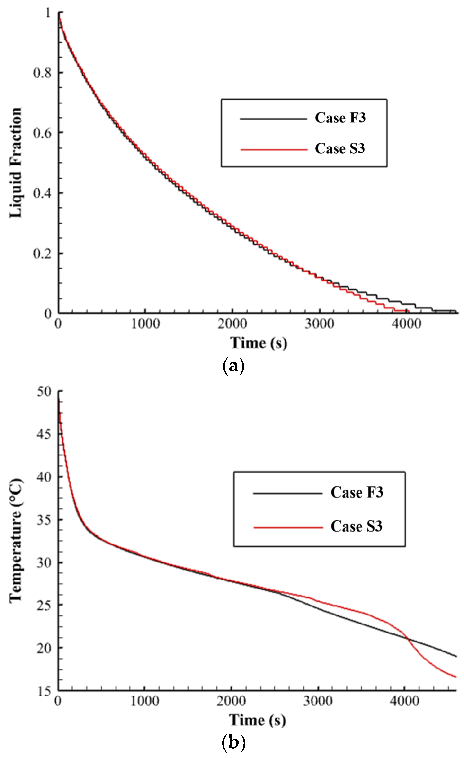
| Studied Model | Discharge Time | Heat Release Rate (W) |
|---|---|---|
| Case S3 | 4863 | 33.92 |
| Case F3 | 4873 | 34.39 |
Publisher’s Note: MDPI stays neutral with regard to jurisdictional claims in published maps and institutional affiliations. |
© 2022 by the authors. Licensee MDPI, Basel, Switzerland. This article is an open access article distributed under the terms and conditions of the Creative Commons Attribution (CC BY) license (https://creativecommons.org/licenses/by/4.0/).
Share and Cite
Ju, Y.; Babaei-Mahani, R.; Ibrahem, R.K.; Khakberdieva, S.; Karim, Y.S.; Abdalla, A.N.; Mohamed, A.; Mahmoud, M.Z.; Ali, H.M. Discharge Enhancement in a Triple-Pipe Heat Exchanger Filled with Phase Change Material. Nanomaterials 2022, 12, 1605. https://doi.org/10.3390/nano12091605
Ju Y, Babaei-Mahani R, Ibrahem RK, Khakberdieva S, Karim YS, Abdalla AN, Mohamed A, Mahmoud MZ, Ali HM. Discharge Enhancement in a Triple-Pipe Heat Exchanger Filled with Phase Change Material. Nanomaterials. 2022; 12(9):1605. https://doi.org/10.3390/nano12091605
Chicago/Turabian StyleJu, Yongfeng, Roohollah Babaei-Mahani, Raed Khalid Ibrahem, Shoira Khakberdieva, Yasir Salam Karim, Ahmed N. Abdalla, Abdullah Mohamed, Mustafa Z. Mahmoud, and Hafiz Muhammad Ali. 2022. "Discharge Enhancement in a Triple-Pipe Heat Exchanger Filled with Phase Change Material" Nanomaterials 12, no. 9: 1605. https://doi.org/10.3390/nano12091605
APA StyleJu, Y., Babaei-Mahani, R., Ibrahem, R. K., Khakberdieva, S., Karim, Y. S., Abdalla, A. N., Mohamed, A., Mahmoud, M. Z., & Ali, H. M. (2022). Discharge Enhancement in a Triple-Pipe Heat Exchanger Filled with Phase Change Material. Nanomaterials, 12(9), 1605. https://doi.org/10.3390/nano12091605