
Piezoelectric Property of Electrospun PVDF Nanofibers as Linking Tips of Artificial-Hair-Cell Structures in Cochlea

 ,
,  and
and
Abstract
:1. Introduction
2. Materials and Methods
2.1. Materials
2.2. Solution Preparation
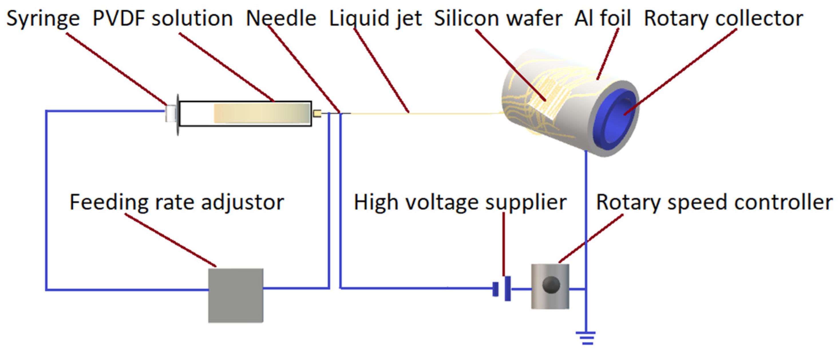
2.3. Electrospinning Methodology Application
2.4. Characterization
3. Results and Discussion
3.1. Optimal Parameters for Electrospun PVDF Fibers
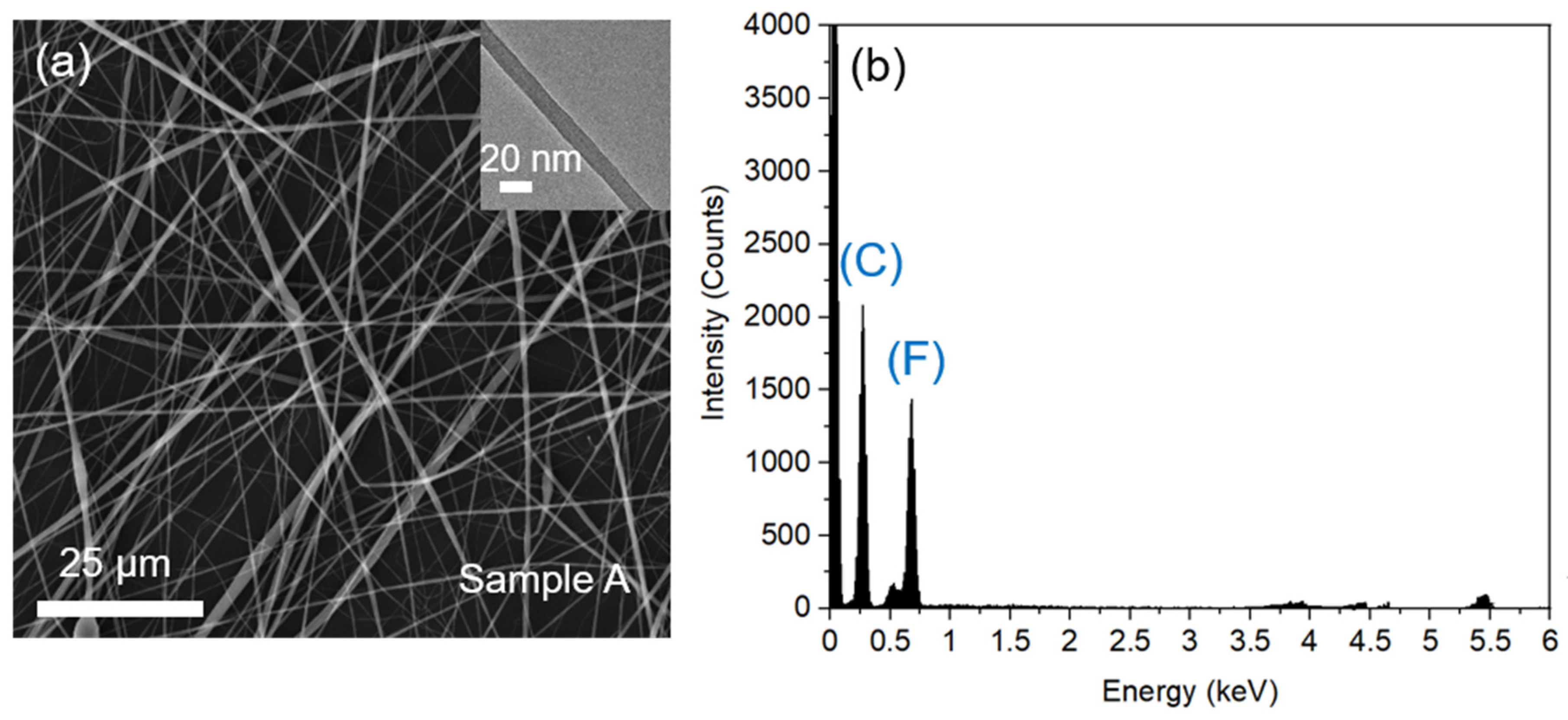
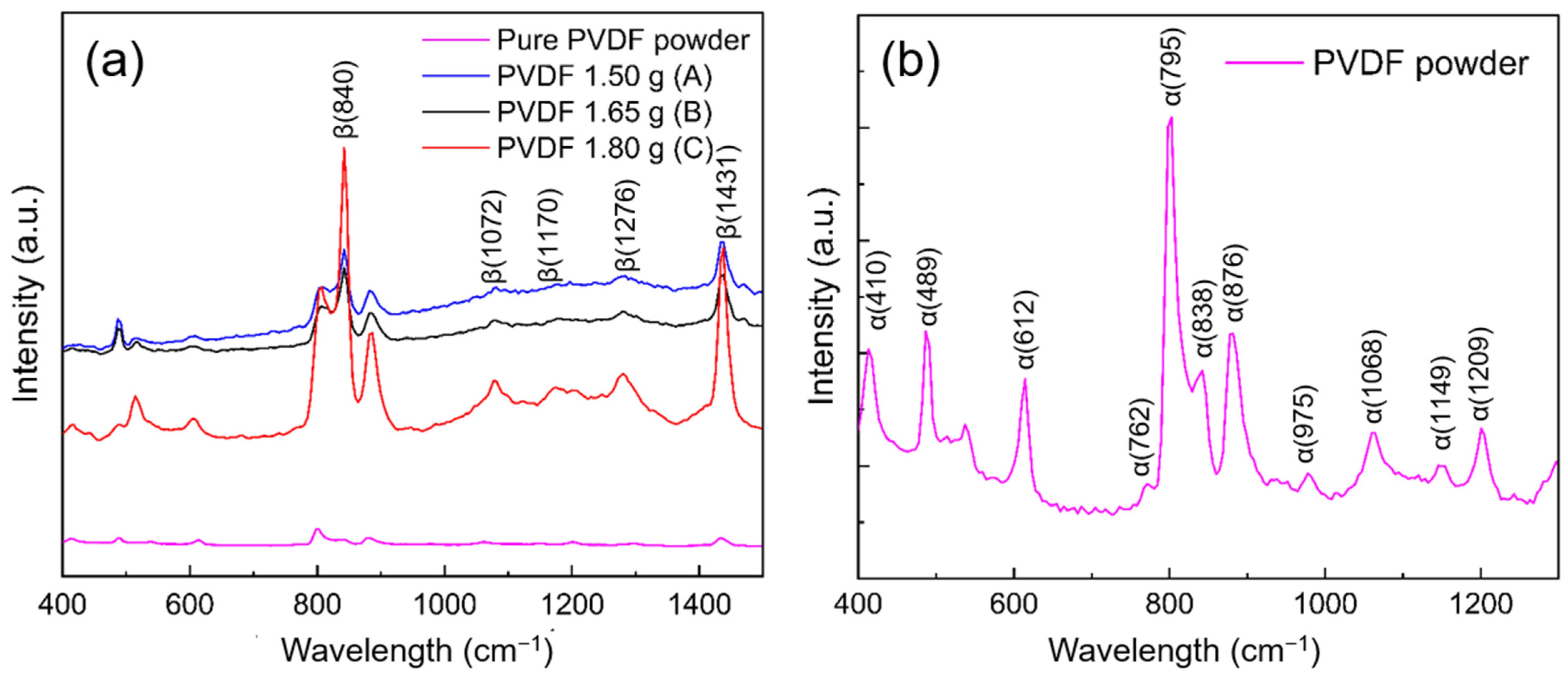
3.2. Structural and Phase Features of the PVDF Nanofibers
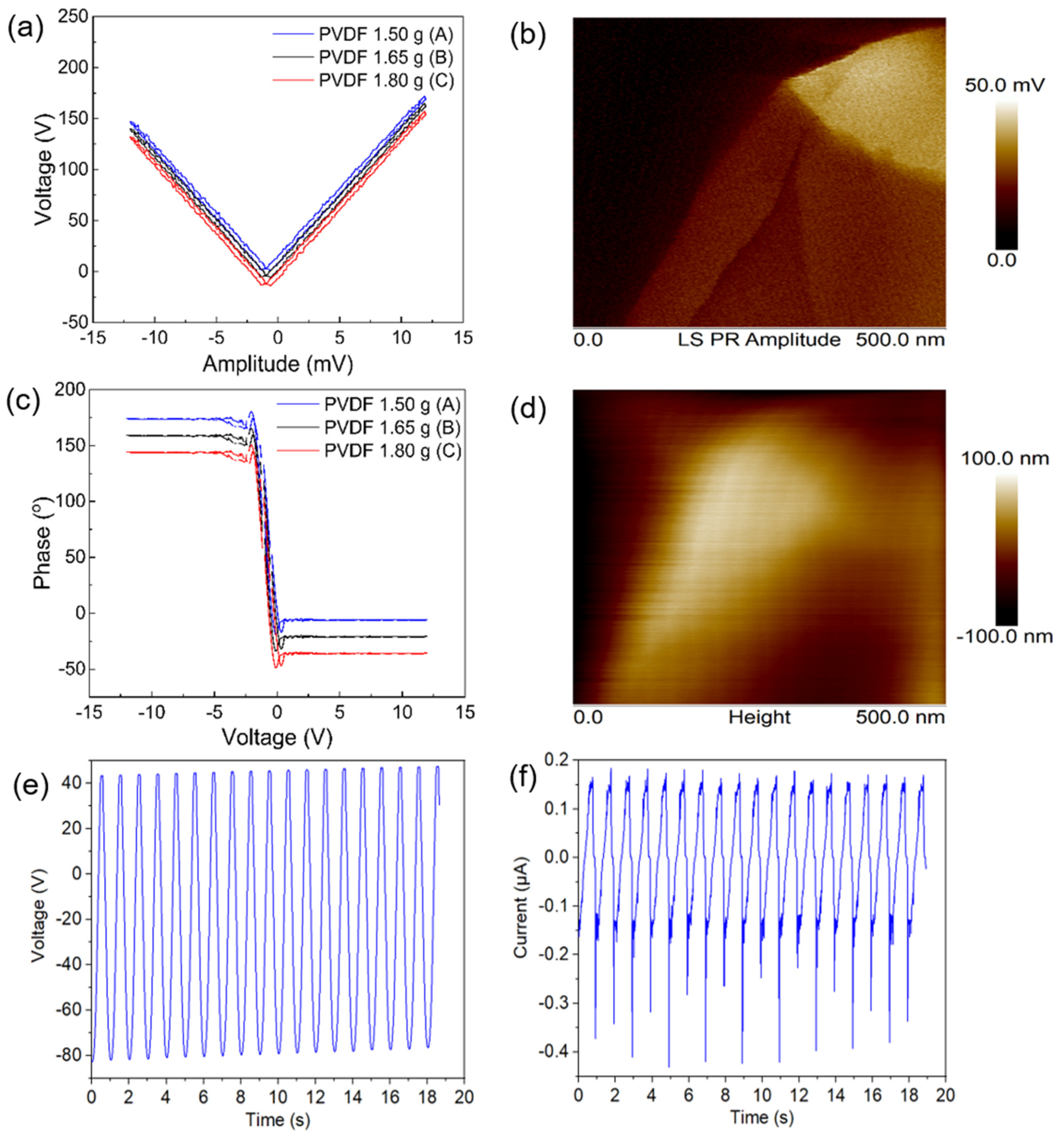
3.3. Piezoelectric Response of Electrospun PVDF Fibers
4. Conclusions
Supplementary Materials
Author Contributions
Funding
Institutional Review Board Statement
Informed Consent Statement
Data Availability Statement
Acknowledgments
Conflicts of Interest
References
- Chadha, S.; Kamenov, K.; Cieza, A. The world report on hearing, 2021. Bull. World Health Organ. 2021, 99, 242. [Google Scholar] [CrossRef] [PubMed]
- Kazmierczak, P.; Sakaguchi, H.; Tokita, J.; Wilson-Kubalek, E.M.; Milligan, R.A.; Müller, U.; Kachar, B. Cadherin 23 and protocadherin 15 interact to form tip-link filaments in sensory hair cells. Nature 2007, 449, 87–91. [Google Scholar] [CrossRef]
- Qiu, X.; Müller, U. Mechanically gated ion channels in mammalian hair cells. Front. Cell. Neurosci. 2018, 12, 100. [Google Scholar] [CrossRef] [PubMed] [Green Version]
- Liu, C. Recent developments in polymer MEMS. Adv. Mater. 2007, 19, 3783–3790. [Google Scholar] [CrossRef]
- Madou, M.J. Fundamentals of Microfabrication: The Science of Miniaturization; CRC Press: Boca Raton, FL, USA, 2018. [Google Scholar]
- Qi, Y.; McAlpine, M.C. Nanotechnology-enabled flexible and biocompatible energy harvesting. Energy Environ. Sci. 2010, 3, 1275–1285. [Google Scholar] [CrossRef]
- Liang, Z.; Guo, X.; Yang, B.; Zhang, T. Design and characterization of a novel biaxial bionic hair flow sensor based on resonant sensing. Sensors 2020, 20, 4483. [Google Scholar] [CrossRef] [PubMed]
- Chang, W.Y.; Chu, C.H.; Lin, Y.C. A flexible piezoelectric sensor for microfluidic applications using polyvinylidene fluoride. IEEE Sens. J. 2008, 8, 495–500. [Google Scholar] [CrossRef]
- Tomimatsu, Y.; Kuwana, K.; Kobayashi, T.; Itoh, T.; Maeda, R. A piezoelectric flow sensor for wake-up switch of wireless sensor network node. In Proceedings of the 2012 Second Workshop on Design, Control and Software Implementation for Distributed MEMS, Besancon, France, 2–3 April 2012; pp. 53–57. [Google Scholar] [CrossRef]
- Inaoka, T.; Shintaku, H.; Nakagawa, T.; Kawano, S.; Ogita, H.; Sakamoto, T.; Hamanishi, S.; Wada, H.; Ito, J. Piezoelectric materials mimic the function of the cochlear sensory epithelium. Proc. Natl. Acad. Sci. USA. 2011, 108, 18390–18395. [Google Scholar] [CrossRef] [Green Version]
- Sengupta, D.; Kottapalli, A.G.P.; Chen, S.H.; Miao, J.M.; Kwok, C.Y.; Triantafyllou, M.S.; Warkiani, M.E.; Asadnia, M. Characterization of single polyvinylidene fluoride (PVDF) nanofiber for flow sensing applications. AIP Adv. 2017, 7, 105205. [Google Scholar] [CrossRef]
- Stassi, S.; Cauda, V.; Canavese, G.; Pirri, C.F. Flexible tactile sensing based on piezoresistive composites: A review. Sensors 2014, 14, 5296–5332. [Google Scholar] [CrossRef] [Green Version]
- Shi, X.; Zhou, W.; Ma, D.; Ma, Q.; Bridges, D.; Ma, Y.; Hu, A. Electrospinning of Nanofibers and Their Applications for Energy Devices. J. Nanomater. 2015, 2015, 140716. [Google Scholar] [CrossRef] [Green Version]
- Hattori, T.; Kanaoka, M.; Ohigashi, H. Improved piezoelectricity in thick lamellar β-form crystals of poly(vinylidene fluoride) crystallized under high pressure. J. Appl. Phys. 1996, 79, 2016–2022. [Google Scholar] [CrossRef]
- Bohlén, M.; Bolton, K. Inducing the β-phase of poly (vinylidene fluoride)—A review. Annu. Rev. Nanosci. Nanotechnol. 2015, 1, 1–14. [Google Scholar]
- Martin, C.R. Membrane-based synthesis of nanomaterials. Chem. Mater. 1996, 8, 1739–1746. [Google Scholar] [CrossRef]
- van de Witte, J.F.p.; Dijkstra, P.J.; van den Berg, J.W.A. Phase separation processes in polymer solutions in relation to membrane formation. J. Memb. Sci. 1996, 117, 1–31. [Google Scholar] [CrossRef] [Green Version]
- Wu, Z.; Cheng, T.; Wang, Z.L. Self-powered sensors and systems based on nanogenerators. Sensors 2020, 20, 2925. [Google Scholar] [CrossRef] [PubMed]
- Jang, J.; Jang, J.H.; Choi, H. Biomimetic Artificial Basilar Membranes for Next-Generation Cochlear Implants. Adv. Healthc. Mater. 2017, 6, 1700674. [Google Scholar] [CrossRef]
- Chen, D.; Chen, K.; Brown, K.; Hang, A.; Zhang, J.X.J. Liquid-phase tuning of porous PVDF-TrFE film on flexible substrate for energy harvesting. Appl. Phys. Lett. 2017, 110, 153902. [Google Scholar] [CrossRef] [Green Version]
- Wang, Y.R.; Zheng, J.M.; Ren, G.Y.; Zhang, P.H.; Xu, C. A flexible piezoelectric force sensor based on PVDF fabrics. Smart Mater. Struct. 2011, 20, 045009. [Google Scholar] [CrossRef]
- Al-Saygh, A.; Ponnamma, D.; AlMaadeed, M.A.A.; Poornima Vijayan, P.; Karim, A.; Hassan, M.K. Flexible pressure sensor based on PVDF nanocomposites containing reduced graphene oxide-titania hybrid nanolayers. Polymers 2017, 9, 33. [Google Scholar] [CrossRef]
- Soergel, E. Piezoresponse force microscopy (PFM). J. Phys. D Appl. Phys. 2011, 44, 464003. [Google Scholar] [CrossRef]
- Sturm, H.; Stark, W.; Bovtoun, V.; Schulz, E. Methods for simultaneous measurements of topography and local electrical properties using scanning force microscopy. In Proceedings of the 9th International Symposium on Electrets (ISE 9) Proceedings, Shanghai, China, 27 September 1996; pp. 223–228. [Google Scholar] [CrossRef]
- Sajkiewicz, P.; Wasiak, A.; Goclowski, Z. Phase transitions during stretching of poly(vinylidene fluoride). Eur. Polym. J. 1999, 35, 423–429. [Google Scholar] [CrossRef]
- You, A.; Be, M.A.Y.; In, I. An infrared study of phase-III poly (vinylidene fluoride). J. Appl. Phys. 2008, 50, 6106. [Google Scholar]
- Boccaccio, T.; Bottino, A.; Capannelli, G.; Piaggio, P. Characterization of PVDF membranes by vibrational spectroscopy. J. Memb. Sci. 2002, 210, 315–329. [Google Scholar] [CrossRef]
- Lopes, A.C.; Costa, C.M.; Tavares, C.J.; Neves, I.C.; Lanceros-Mendez, S. Nucleation of the electroactive γ phase and enhancement of the optical transparency in low filler content poly(vinylidene)/clay nanocomposites. J. Phys. Chem. C 2011, 115, 18076–18082. [Google Scholar] [CrossRef]
- Gregorio, R. Determination of the α, β, and γ crystalline phases of poly(vinylidene fluoride) films prepared at different conditions. J. Appl. Polym. Sci. 2006, 100, 3272–3279. [Google Scholar] [CrossRef]
- Cross, L.E. Ferroelectric materials for electromechanical transducer applications. Mater. Chem. Phys. 1996, 43, 108–115. [Google Scholar] [CrossRef]
- Xin, Y.; Tian, H.; Guo, C.; Li, X.; Sun, H.; Wang, P.; Lin, J.; Wang, S.; Wang, C. PVDF tactile sensors for detecting contact force and slip: A review. Ferroelectrics 2016, 504, 31–45. [Google Scholar] [CrossRef]
- Holmes-Siedle, A.G.; Wilson, P.D.; Verrall, A.P. PVdF: An electronically-active polymer for industry. Mater. Des. 1983, 4, 910–918. [Google Scholar] [CrossRef]
- Dutta, B.; Kar, E.; Bose, N.; Mukherjee, S. Significant enhancement of the electroactive β-phase of PVDF by incorporating hydrothermally synthesized copper oxide nanoparticles. RSC Adv. 2015, 5, 105422–405434. [Google Scholar] [CrossRef]
- Park, J.S. Electrospinning and its applications. Adv. Nat. Sci. Nanosci. Nanotechnol. 2010, 1, 043002. [Google Scholar] [CrossRef] [Green Version]
- Ruan, L.; Yao, X.; Chang, Y.; Zhou, L.; Qin, G.; Zhang, X. Properties and applications of the β phase poly(vinylidene fluoride). Polymers 2018, 10, 228. [Google Scholar] [CrossRef] [Green Version]
- Chen, S.; Yao, K.; Tay, F.E.H.; Liow, C.L. Ferroelectric poly(vinylidene fluoride) thin films on Si substrate with the Β phase promoted by hydrated magnesium nitrate. J. Appl. Phys. 2007, 102, 104108. [Google Scholar] [CrossRef]
- Song, R.; Yang, D.; He, L. Effect of surface modification of nanosilica on crystallization, thermal and mechanical properties of poly(vinylidene fluoride). J. Mater. Sci. 2007, 42, 8408–8417. [Google Scholar] [CrossRef]
- Zhu, Y.; Wang, J.; Zhang, F.; Gao, S.; Wang, A.; Fang, W.; Jin, J. Zwitterionic Nanohydrogel Grafted PVDF Membranes with Comprehensive Antifouling Property and Superior Cycle Stability for Oil-in-Water Emulsion Separation. Adv. Funct. Mater. 2018, 28, 1804121. [Google Scholar] [CrossRef]
- Cordeiro, A.L.; Nitschke, M.; Janke, A.; Helbig, R.; D’Souza, F.; Donnelly, G.T.; Willemsen, P.R.; Werner, C. Fluorination of poly(dimethylsiloxane) surfaces by low pressure CF 4 plasma—Physicochemical and antifouling properties. Express Polym. Lett. 2009, 3, 70–83. [Google Scholar] [CrossRef]
- Sultana, T.; Georgiev, G.L.; Auner, G.; Newaz, G.; Herfurth, H.J.; Patwa, R. XPS analysis of laser transmission micro-joint between poly (vinylidene fluoride) and titanium. Appl. Surf. Sci. 2008, 255, 2569–2573. [Google Scholar] [CrossRef]
- Chew, N.G.P.; Zhao, S.; Malde, C.; Wang, R. Superoleophobic surface modification for robust membrane distillation performance. J. Memb. Sci. 2017, 541, 162–173. [Google Scholar] [CrossRef]
- Serhan, M.; Sprowls, M.; Jackemeyer, D.; Long, M.; Perez, I.D.; Maret, W.; Tao, N.; Forzani, E. Total iron measurement in human serum with a smartphone. In Proceedings of the 2019 AIChE Annual Meeting, Orlando, FL, USA, 10–15 November 2019. [Google Scholar] [CrossRef]
- Li, J.H.; Shao, X.S.; Zhou, Q.; Li, M.Z.; Zhang, Q.Q. The double effects of silver nanoparticles on the PVDF membrane: Surface hydrophilicity and antifouling performance. Appl. Surf. Sci. 2013, 265, 663–670. [Google Scholar] [CrossRef]
- Solutions, P. An Introduction to Physical Properties; John Wiley & Sons, Inc.: Hoboken, NJ, USA, 2002; Volume 3, ISBN 0471389293. [Google Scholar]
- LeMasurier, M.; Gillespie, P.G. Hair-cell mechanotransduction and cochlear amplification. Neuron 2005, 48, 403–415. [Google Scholar] [CrossRef] [Green Version]
- Yoshizawa, M.; Jeffery, W.R.; Van Netten, S.M.; McHenry, M.J. The sensitivity of lateral line receptors and their role in the behavior of Mexican blind cavefish (Astyanax mexicanus). J. Exp. Biol. 2014, 217, 886–895. [Google Scholar] [CrossRef] [PubMed] [Green Version]
- Mazoochi, T.; Hamadanian, M.; Ahmadi, M.; Jabbari, V. Investigation on the morphological characteristics of nanofiberous membrane as electrospun in the different processing parameters. Int. J. Ind. Chem. 2012, 3, 2. [Google Scholar] [CrossRef] [Green Version]
- Can-Herrera, L.A.; Oliva, A.I.; Dzul-Cervantes, M.A.A.; Pacheco-Salazar, O.F.; Cervantes-Uc, J.M. Morphological and mechanical properties of electrospun polycaprolactone scaffolds: Effect of applied voltage. Polymers 2021, 13, 662. [Google Scholar] [CrossRef] [PubMed]
- Nasir, M.; Matsumoto, H.; Danno, T.; Minagawa, M.; Irisawa, T.; Shioya, M.; Tanioka, A. Control of diameter, morphology, and structure of PVDF nanofiber fabricated by electrospray deposition. J. Polym. Sci. Part B Polym. Phys. 2006, 44, 779–786. [Google Scholar] [CrossRef]
- Motamedi, A.S.; Mirzadeh, H.; Hajiesmaeilbaigi, F.; Bagheri-Khoulenjani, S.; Shokrgozar, M. Effect of electrospinning parameters on morphological properties of PVDF nanofibrous scaffolds. Prog. Biomater. 2017, 6, 113–123. [Google Scholar] [CrossRef] [PubMed]
- Bae, J.; Baek, I.; Choi, H. Efficacy of piezoelectric electrospun nanofiber membrane for water treatment. Chem. Eng. J. 2017, 307, 670–678. [Google Scholar] [CrossRef]
- Gregorio, R.; Ueno, E.M. Effect of crystalline phase, orientation and temperature on the dielectric properties of poly (vinylidene fluoride) (PVDF). J. Mater. Sci. 1999, 34, 4489–4500. [Google Scholar] [CrossRef]


| Samples | C 1s (At%) | O 1s (At%) | F 1s (At%) | F/C | O/C |
|---|---|---|---|---|---|
| Pure PVDF powder | 54.64 | 1.77 | 43.59 | 0.80 | 0.032 |
| Sample A | 59.58 | 1.78 | 38.65 | 0.65 | 0.030 |
| Sample B | 55.33 | 0.85 | 43.82 | 0.79 | 0.015 |
| Sample C | 57.30 | 1.04 | 41.66 | 0.73 | 0.018 |
| Samples | CF2 (At%) | CH2 (At%) | -COO (At%) | CH (At%) | CF3 (At%) |
|---|---|---|---|---|---|
| Pure PVDF powder | 20.22 | 26.35 | 2.89 | 3.04 | 0.48 |
| Sample A | 19.04 | 23.51 | 3.08 | 11.99 | 0.36 |
| Sample B | 20.62 | 22.19 | 2.68 | 6.12 | 0.30 |
| Sample C | 20.74 | 23.59 | 2.82 | 6.67 | 0.74 |
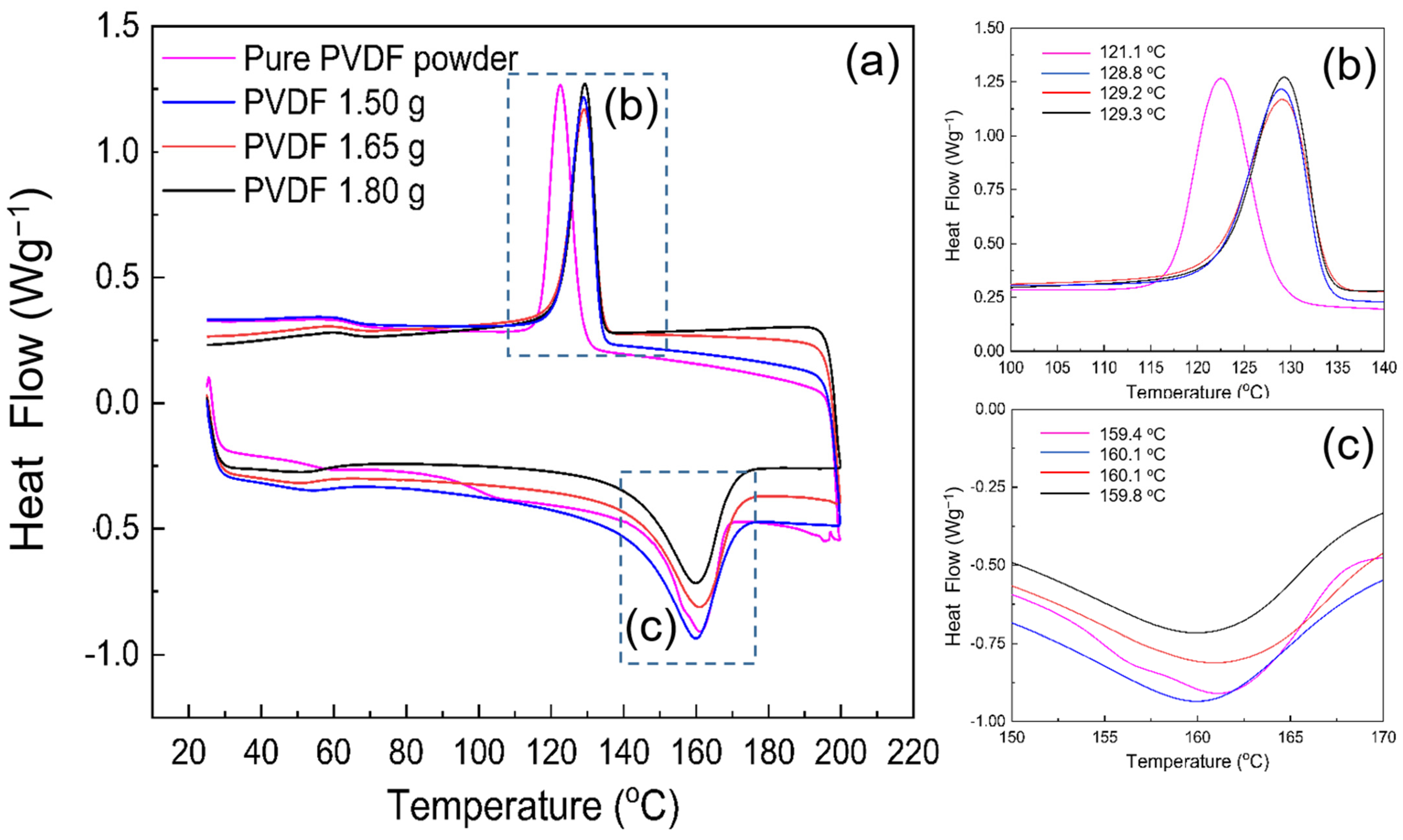
| Samples | Tc [°C] | Tm [°C] | ∆Hm [J.g−1] | XDSC |
|---|---|---|---|---|
| Pure PVDF powder | 121.1 | 160.1 | 45.2 | 44.2 |
| Sample A | 128.8 | 159.4 | 46.7 | 45.1 |
| Sample B | 129.2 | 159.8 | 43.3 | 39.7 |
| Sample C | 129.3 | 160.1 | 41.1 | 39.1 |
Publisher’s Note: MDPI stays neutral with regard to jurisdictional claims in published maps and institutional affiliations. |
© 2022 by the authors. Licensee MDPI, Basel, Switzerland. This article is an open access article distributed under the terms and conditions of the Creative Commons Attribution (CC BY) license (https://creativecommons.org/licenses/by/4.0/).
Share and Cite
Sabouni Tabari, R.; Chen, Y.; Thummavichai, K.; Zhang, Y.; Saadi, Z.; Neves, A.I.S.; Xia, Y.; Zhu, Y. Piezoelectric Property of Electrospun PVDF Nanofibers as Linking Tips of Artificial-Hair-Cell Structures in Cochlea. Nanomaterials 2022, 12, 1466. https://doi.org/10.3390/nano12091466
Sabouni Tabari R, Chen Y, Thummavichai K, Zhang Y, Saadi Z, Neves AIS, Xia Y, Zhu Y. Piezoelectric Property of Electrospun PVDF Nanofibers as Linking Tips of Artificial-Hair-Cell Structures in Cochlea. Nanomaterials. 2022; 12(9):1466. https://doi.org/10.3390/nano12091466
Chicago/Turabian StyleSabouni Tabari, Rana, Yu Chen, Kunyapat Thummavichai, Yan Zhang, Zakaria Saadi, Ana I. S. Neves, Yongde Xia, and Yanqiu Zhu. 2022. "Piezoelectric Property of Electrospun PVDF Nanofibers as Linking Tips of Artificial-Hair-Cell Structures in Cochlea" Nanomaterials 12, no. 9: 1466. https://doi.org/10.3390/nano12091466
APA StyleSabouni Tabari, R., Chen, Y., Thummavichai, K., Zhang, Y., Saadi, Z., Neves, A. I. S., Xia, Y., & Zhu, Y. (2022). Piezoelectric Property of Electrospun PVDF Nanofibers as Linking Tips of Artificial-Hair-Cell Structures in Cochlea. Nanomaterials, 12(9), 1466. https://doi.org/10.3390/nano12091466