Abstract
GaN-based blue micro-light-emitting diodes (μ-LEDs) with different structures were designed, of which the effect of quantum well (QW) structure on modulation bandwidth was numerically explored. By using trapezoidal QWs, the quantum-confined Stark effect (QCSE) can be reduced, leading to an enhanced electron-hole wave function overlap, thereby increasing the recombination rate and reducing the differential carrier lifetime. In addition, the improved hole transport also creates favorable conditions for shortening the differential carrier lifetime. Furthermore, by comparing with traditional μ-LEDs with different thicknesses of QW, the modulation bandwidth of μ-LEDs with trapezoidal QWs exhibits a large advantage at lower current densities of below 2 kA/cm2.
1. Introduction
Light-emitting diode (LED) has undergone great developments since its birth, penetrating every corner of our lives. Recently, great opportunities for LEDs are beginning to emerge in visible light communications (VLC) [1,2]. However, the major factor limiting the performance of GaN/InGaN LED-based VLC systems is the modulation bandwidth of the LEDs, which is far from the needs of modern wireless communication systems, creating an enormous obstacle to its application in VLC [3,4].
The modulation bandwidth of LEDs is inversely related to the Resistance–Capacitance (RC) time constant and the carrier lifetime [5,6], and generally, the larger one plays a major role. The pixel size of LEDs has been reported to be an important factor affecting their inherent RC time constant [5,6,7]. Thus, the limitation of the RC time constant on the modulation bandwidth of LEDs can be reduced by reducing the size of the LEDs [8,9,10]. Previous studies have found that the modulation speed of LEDs can be increased by reducing the thickness of the quantum barrier (QB), due to the enhancement of the recombination rate caused by the amelioration of the carrier distribution [11]. Carrier lifetime is also a key factor of the frequency response performance and usually decreases with increasing current density [12,13]. Numerous studies have shown that high current density is the cornerstone for supporting high modulation speed [14,15,16]. With this background, excellent thermal performance, the negligible RC time constant [8,12], and high operating current density make micro-light-emitting diodes (μ-LEDs) one of the most attractive candidates for high-speed VLC applications [17,18,19,20,21]. However, a disadvantage in polar GaN/InGaN-based μ-LEDs is the quantum-confined Stark effect (QCSE), in which the polarization electric field separates the wave functions of electrons and holes, leading to a reduction in the recombination rate and an increase in carrier lifetime [22,23,24]. Besides, high operating current densities often outweigh the benefits, as the resulting efficiency droop, so it makes sense to achieve higher modulation bandwidths at lower current densities [25]. Compared with conventional μ-LEDs grown on the c-plane, semi-polar and non-polar μ-LEDs exhibit weaker QCSE, higher overlaps of electron-hole wave functions, and shorter carrier lifetimes, attracting more and more research interest in recent years [9,16,21,25,26].
Through the great efforts of researchers, the modulation bandwidth of μ-LEDs measured in the laboratory has been significantly improved [8,27,28,29]. However, most studies focused on the improvement of modulation bandwidth by adopting new materials and new LED structures, but the mechanisms have not been well analyzed, which is crucial to developing μ-LEDs with high modulation bandwidth. It is vital to study the influence of the effects of quantum well (QW) structures on the modulation bandwidth and to clarify the underlying physical mechanism, which will provide a valuable guide for μ-LEDs fabrication in future VLC applications.
Simulation provides a device design method without relying on the epitaxial process, saving development costs. In this article, APSYS (an acronym for Advanced Physical Models of Semiconductor Devices) has been used to study the modulation bandwidth of GaN-based blue μ-LEDs with different QW structures for VLC applications [30]. In addition, the effect of band structure has been taken into account, and a series of diagrams have been constructed to illustrate the physical mechanisms involved.
2. Theoretical Model and Device Structure
The carrier recombination rate (R) is defined as the number of carriers recombined per unit time and unit volume. Based on the ABC efficiency model [31,32,33], the R is mainly composed of Shockley–Read–Hall (SRH) recombination, radiative recombination, and Auger recombination, which are proportional to the first, second, and third power of the carrier concentration, respectively [34,35,36]. The carrier generation rate (G) is defined as the number of carriers generated per unit time and unit volume. Under equilibrium conditions, the carrier generation rate in the active region of a μ-LED is approximately equal to the recombination rate in it, expressed by the following formula [35,37]:
where A, B, and C represent SRH recombination coefficient, radiative recombination coefficient, and Auger recombination coefficient, respectively, n represents electron concentration, and p represents hole concentration.
Under high current density, the excess carriers dominate, while the excess electron concentration balances with the excess hole concentration [24,38,39,40,41]. When a high-frequency small-amplitude signal is injected at high current density, the increase in electron concentration is equal to that of hole concentration, and the increase in carrier concentration is much smaller than the carrier concentration at direct current (DC) bias. Therefore, the relationship between the increment of the carrier generation rate (ΔG) and the increment of the carrier concentration is (Δn) as follows:
The differential carrier lifetime (τ) can be obtained from the derivative of the carrier generation rate with respect to the carrier concentration, expressed by the following formula [12,42]:
In the frequency response of μ-LEDs, the −3 dB modulation bandwidth (f−3dB) is defined as the corresponding frequency when the normalized power drops to half of the maximum value. Generally, the differential carrier lifetime has a relationship with the 3 dB modulation bandwidth of the LED as follows [12,25]:
In the physical model of simulation, band offset, internal loss, and the SRH recombination lifetimes are set to 70:30, 2000 m−1, and 200 ns [34,43,44], respectively. Moreover, the Auger recombination coefficient is set to 3 × 10⁻³¹ cm−6/s [43,44]. Built-in polarizations ranging from 20% to 80% of theoretical predictions have been reported, and 50% are chosen for simulation in this study [34,45,46]. Other physical parameters can be found in references [47].
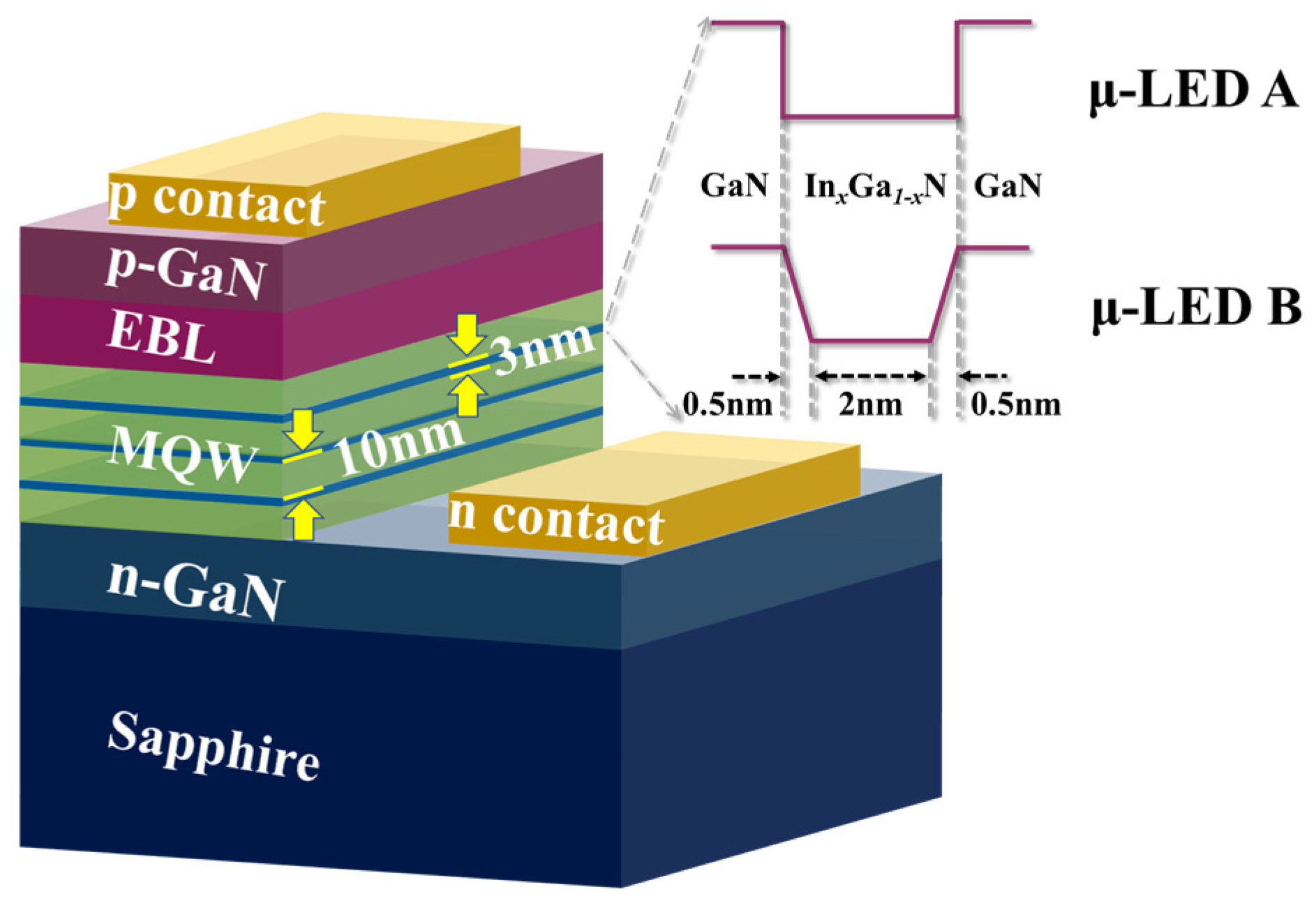
The structures of the μ-LEDs in this work are shown in Figure 1. There is a layer of 10 μm thick sapphire substrate at the bottom, followed by a 3 μm thick GaN layer with an n-type doping concentration of 5 × 1018 cm−3 and a three-period GaN/InGaN multiple quantum well (MQW) layer. The thickness of QBs is 10 nm, where the n-type doping concentration is 3 × 1017 cm−3. The indium content in QWs is set to 20% to ensure an emission at a wavelength of around 450 nm. On the top of the active area, there is a 20 nm thick Al0.23Ga0.77N as an electron blocking layer (EBL) with a p-type doping concentration of 1.2 × 1018 cm−3 and a 50 nm thick GaN as a cladding layer with a p-type doping concentration of 1.2 × 1018 cm−3. The ohmic contact on the cladding layer is defined as the p-electrode of the μ-LED and that on the n-type GaN layer is defined as the n-electrode of the μ-LED.
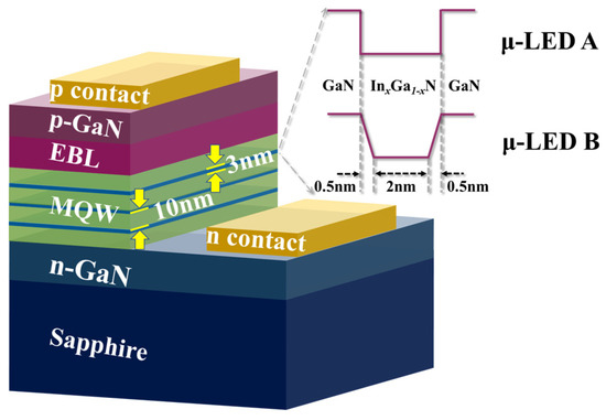
Figure 1.
μ-LEDs with different structures for simulation: μ-LED A with conventional QWs and μ-LED B with trapezoidal QWs.
To study the effect of QWs on the modulation bandwidth, μ-LEDs with two different QW structures have been designed, represented by μ-LED A and μ-LED B in Figure 1. The size of the μ-LED is defined as 20 μm × 20 μm, making the influence of the RC time constant negligible. For μ-LED A, the thickness of one QW is 3 nm with an indium composition of 0.2. For μ-LED B, the thicknesses of the falling side, bottom, and rising side of one QW are 0.5 nm, 2 nm, and 0.5 nm, respectively, with an indium composition ranging from 0 to 0.2. This design enables the two μ-LEDs with the same QW thickness, supporting the subsequent comparative analysis.
3. Results and Discussion
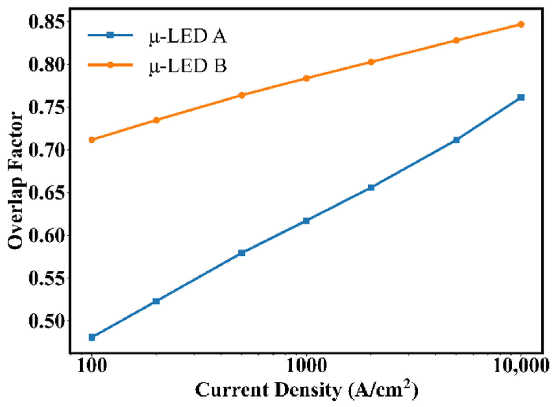
Figure 2 shows the overlap of the electron-hole wave function as a function of current density for μ-LED A and μ-LED B. It can be found that the overlap is far below 1 at low current density due to the separation of the wave functions of electrons and holes caused by QCSE [48]. In addition, the overlaps of μ-LED B are higher than those of μ-LED A, owing to the trapezoidal QW, where there is less lattice mismatch and weaker QCSE, resulting in less separation of electrons and holes [49]. Furthermore, the overlap increases as the current density increases due to the band-filling effect that counteracts the separation of carriers, which also leads to a reduction in the gap between the overlaps of μ-LED A and μ-LED B [37,48]. The above demonstrates that the trapezoidal QW can improve the electron-hole wave function overlap and attenuate the QCSE.
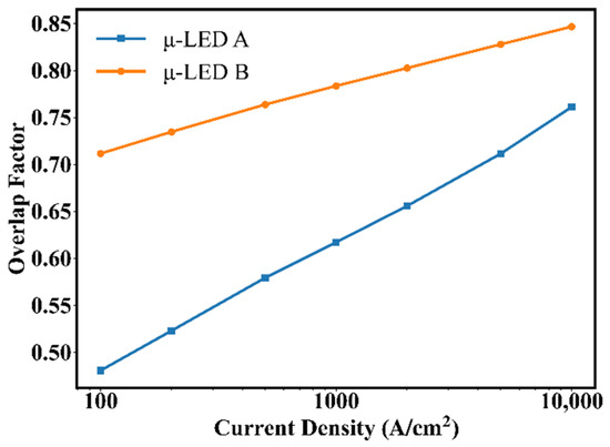
Figure 2.
Overlaps of electron-hole wave function vs. current density for μ-LED A and μ-LED B.
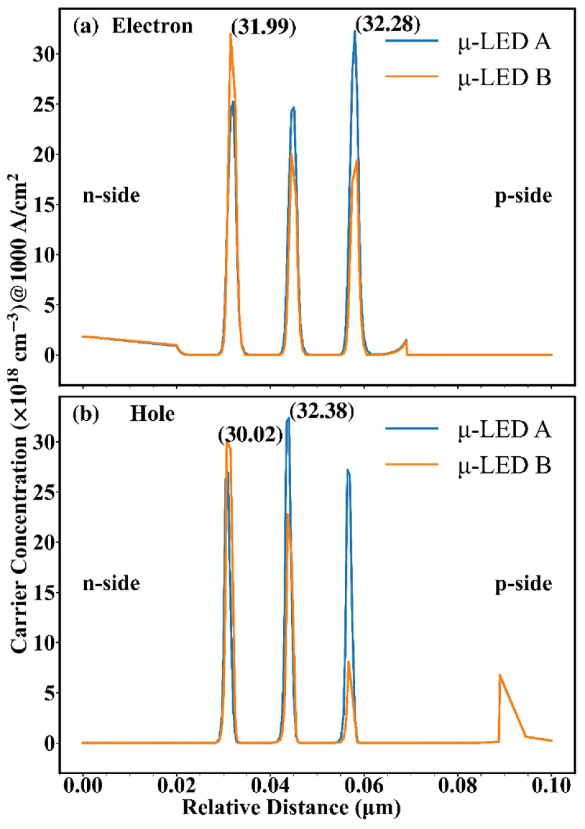
To understand the internal differences between the two devices, Figure 3 shows the electron and hole concentrations as a function of vertical distance relative to the n-side (relative distance) for the two μ-LEDs at 1 kA/cm2. It can be seen that the electron concentration reaches a maximum near the p-side in μ-LED A, but that reaches a maximum near the n-side in μ-LED B. Besides, the hole concentration reaches a maximum at the middle in μ-LED A, but that reaches a maximum near the n-side in μ-LED B. In Figure 3, the peaks of the carrier concentration of the two μ-LEDs are selected and marked. It can be found that the peaks of the carrier concentration of μ-LED A are higher than those of μ-LED B. The above shows that the carrier distribution can be changed by adjusting the structure of QWs, and the cause of which needs to be further analyzed.
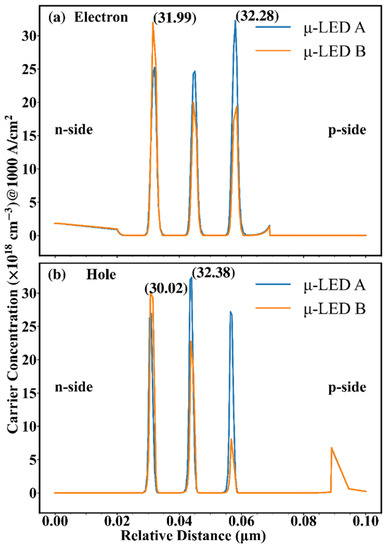
Figure 3.
(a) Electron distribution and (b) hole distribution at 1 kA/cm2 for μ-LED A and μ-LED B.
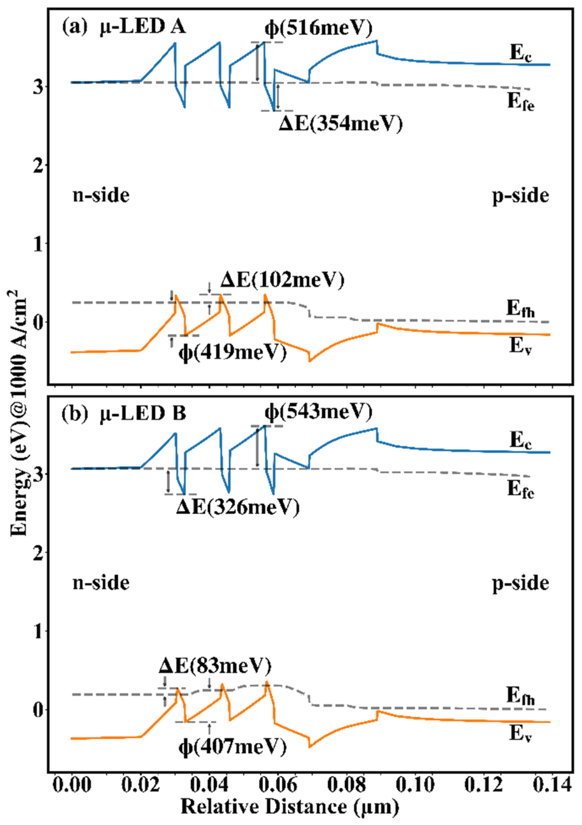
In order to study the variation rules of carrier concentration, Figure 4 shows the energy band as a function of relative distance for the two μ-LEDs at 1 kA/cm2. The Φ is used to represent the energy gap between QB and QW, calculated by the difference between the peak energy of the next QB and the energy valley of the QW, reflecting the transport capacity of carriers. The larger the Φ, the higher the barrier of the QB, the harder the carriers escape, and the weaker the carrier transport. In Figure 4, the Φs are marked at the QW located in the middle position. In the conduction band, it can be found that the Φ of μ-LED B is higher than that of μ-LED A, indicating the stronger electron transport in μ-LED A, which explains the different electron distribution between μ-LED A and μ-LED B in Figure 3. On the contrary, in the valence band, it can be found that the Φ of μ-LED A is higher than that of μ-LED B, indicating the enhanced hole transport in μ-LED B, which explains the different hole distribution between μ-LED A and μ-LED B in Figure 3. The ΔE is used to represent the energy gap in the QW, calculated by the difference between the Fermi energy level and the energy valley of the QW, reflecting the confinement ability of carriers. The larger the ΔE, the easier the carriers are trapped by the QW, and the higher the carrier concentration in the QW. In Figure 4, the ΔEs are marked at the QW with the highest carrier concentration. It can be found that the ΔEs of μ-LED A are higher than those of μ-LED B due to the less lattice mismatch in trapezoidal QWs, which explains the higher peaks of the carrier concentration of μ-LED A than those of μ-LED B in Figure 3.
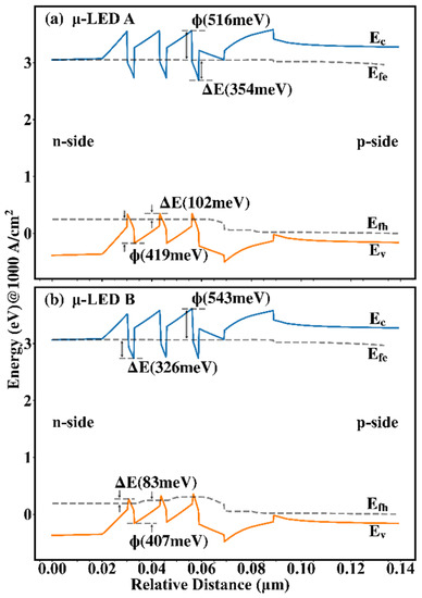
Figure 4.
Energy band of (a) μ-LED A and (b) μ-LED B at 1 kA/cm2.
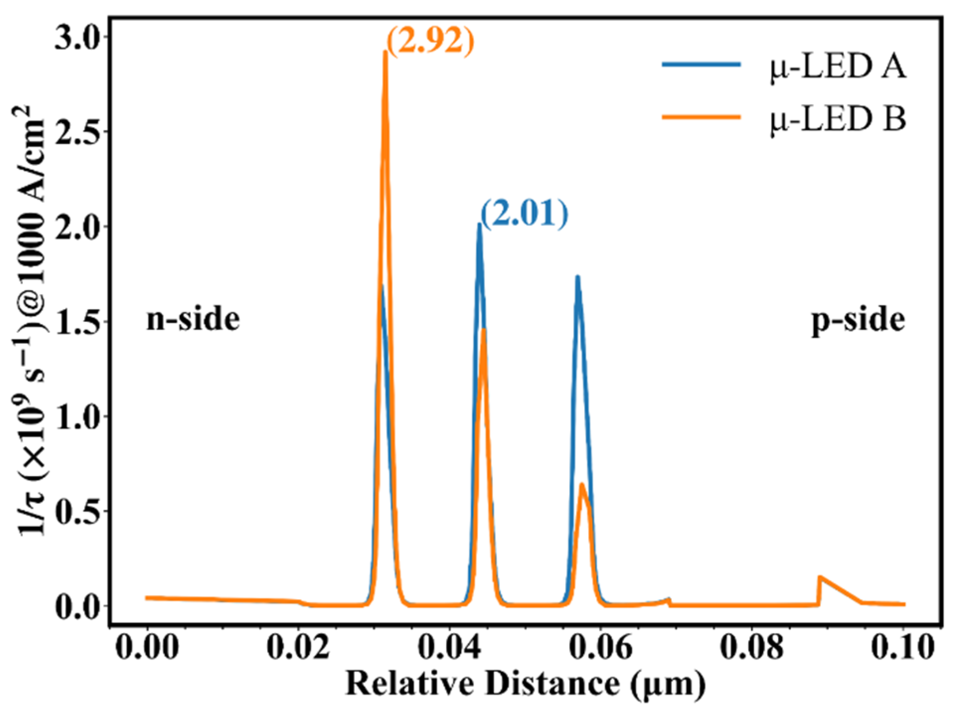
Based on Equations (3) and (4), it can be concluded that the −3 dB modulation bandwidth is positive relative to 1/τ, which is positive relative to carrier concentration. Figure 5 shows 1/τ as a function of relative distance for the two μ-LEDs at 1 kA/cm2. In Equation (3), the concentrations of electrons and holes used to calculate 1/τ are taken from the data at the corresponding locations in Figure 3, which means that 1/τ is also related to the overlap of the electron-hole distribution. Different carrier concentrations lead to different carrier lifetimes in different QWs, and the short-lived carriers reflect the high-frequency portion of the frequency response, which greatly affects the modulation bandwidth. To facilitate the analysis, the peaks of 1/τ of the two μ-LEDs are selected and marked in Figure 5. Combining Figure 3 and Figure 4, it can be found that although a higher ΔE exists in μ-LED A, the improved hole transport makes the peaks of concentrations of electrons and holes of μ-LED B almost coincide. As a result, the peaks of carrier concentrations of μ-LED B and μ-LED A have little difference. Combining Figure 2, Figure 3 and Figure 5, it can be found that although the peak of the carrier concentration of μ-LED B is slightly lower than that of μ-LED A, the huge advantage in the overlap of electron-hole wave functions allows μ-LED B to create a higher peak of 1/τ.
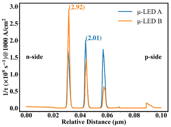
Figure 5.
Reciprocal carrier lifetime vs. relative distance at 1 kA/cm2 for μ-LED A and μ-LED B.
To further illustrate the advantages of μ-LED B, we modify the QW thickness of μ-LED A to 2.5 nm, denoted as μ-LED C (Figure S1). At 1 kA/cm2, we calculated the carrier distribution and carrier wave function of μ-LED C (Figure S2 and Figure S3), then compared the peak electron concentration, peak hole concentration, the peak of 1/τ (Figure S4), and the electron-hole wave functions overlap of μ-LED A, μ-LED B, and μ-LED C, respectively, as shown in Table 1. In Table 1, the QWs corresponding to the carrier concentration are marked in brackets, and the QWs from the n-side to the p-side are sequentially denoted as QW1, QW2, and QW3. Compared with μ-LED A, the carrier concentration of μ-LED C is lower, but the advantage in the overlap of electron-hole wave functions gives it a larger 1/τ. Compared with μ-LED B, the electron-hole wave function overlap of μ-LED C is slightly lower, and the peak of electron concentration is slightly lower, but the peak of hole concentration is slightly higher. Importantly, the peaks of the carrier concentration of μ-LED B are concentrated in the same QW, making the peak of 1/τ greatly increased.

Table 1.
Peak electron concentration, peak hole concentration, electron-hole wave function overlap, and peak 1/τ for μ-LED A, μ-LED B, and μ-LED C at 1 kA/cm2.
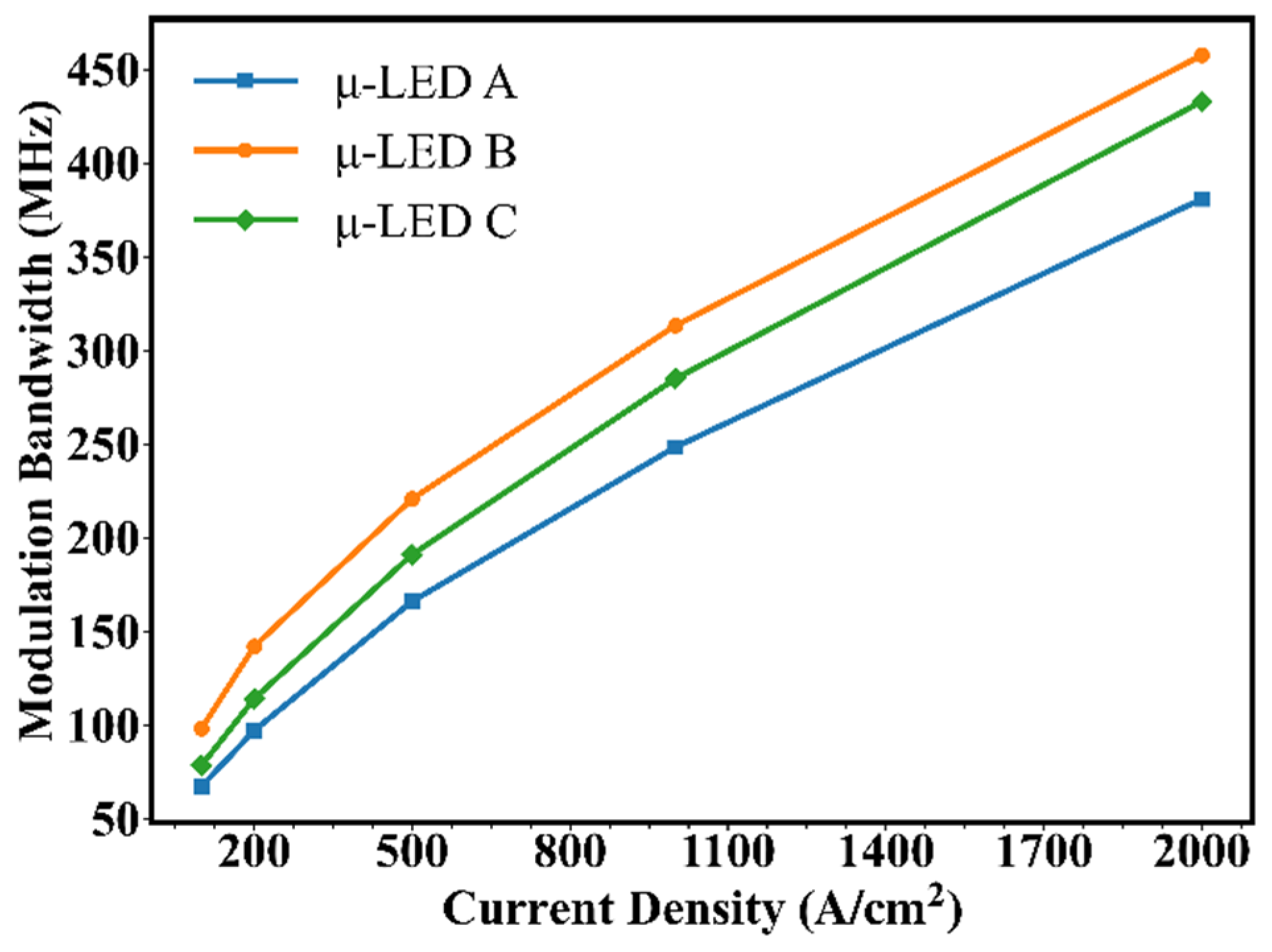
Compared with μ-LED A and μ-LED C, a higher peak of 1/τ in μ-LED B can be found, implying a higher modulation bandwidth for μ-LED B. To verify our analysis, the frequency responses of the three devices are simulated. To generate a high-frequency small-amplitude signal, the current input is set as a Gaussian pulse signal with a signal width of 0.1 ns and a signal amplitude of 1% of the DC bias. In this study, the modulated input signal is converted to optical output signal by the μ-LED and then subjected to Fourier analysis to obtain the frequency response. Figure 6 shows the −3 dB modulation bandwidth vs. the current density of the three μ-LEDs. It can be seen that the −3 dB modulation bandwidth of μ-LEDs increases with increasing current density, which is attributed to the decrease in carrier lifetime. Moreover, the growth of the −3 dB modulation bandwidth of μ-LEDs gradually slows down as the current density increases, attributed to slower carrier concentration growth and more electron leakage. Furthermore, it can be found that the modulation bandwidth of μ-LED B is always higher than that of μ-LED A and μ-LED C as the current density shifts from 100 A/cm2 to 2 kA/cm2, and the modulation bandwidth can be raised to 457.5 MHz. For μ-LED B, the improved hole transport allows the peak of the concentration of holes to meet that of electrons in the same QW, and the large electron-hole wave function overlap greatly reduces the differential carrier lifetime. Actually, a μ-LED with trapezoidal QWs can maximize the peak value of 1/τ, thereby maximizing the modulation bandwidth.
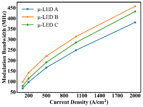
Figure 6.
The −3 dB modulation bandwidth vs. current density for μ-LED A, μ-LED B, and μ-LED C.
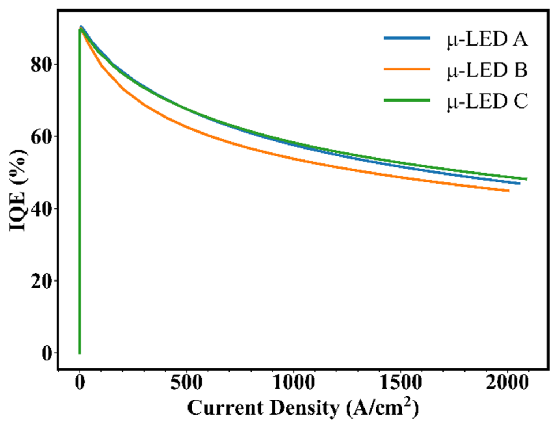
In addition to modulation bandwidth, the quantum efficiency is also an important parameter when considering VLC application scenarios. Therefore, we further compared the internal quantum efficiencies (IQEs) of μ-LED A, μ-LED B, and μ-LED C, as shown in Figure 7. It can be seen that the IQE of μ-LED B is slightly lower than that of μ-LED A and μ-LED C. Furthermore, the relationship between modulation bandwidth and IQE for the μ-LED A, μ-LED B, and μ-LED C was analyzed. At 500 A/cm2, the modulation bandwidths of μ-LED A, μ-LED B, and μ-LED C are 166.1 MHz, 220.8 MHz, and 191.1 MHz, respectively, while the IQEs of those are 66.9%, 62.5%, and 67.4%. Taking μ-LED A sample as a reference, the modulation bandwidth of μ-LED B is increased by about 32.9%, but the IQE is decreased by about 6.57%, while the modulation bandwidth of μ-LED C is increased by about 15.1%, and the IQE is increased by about 0.75%. Our results prove that there is a trade-off between modulation bandwidth and IQE, and we believe that it is worthwhile to optimize the design of MQWs for high-efficiency VLC devices.
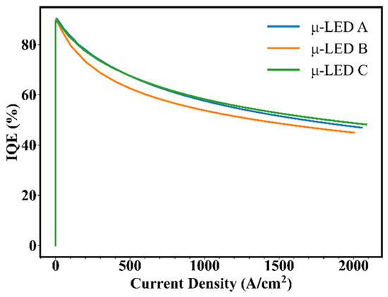
Figure 7.
IQE vs. current density for μ-LED A, μ-LED B, and μ-LED C.
4. Conclusions
The modulation bandwidths of μ-LEDs with different QW structures were compared, and the physical mechanisms involved were discussed in detail. Compared with μ-LEDs with 3 nm and 2.5 nm thick QWs, μ-LEDs with trapezoidal QWs are superior in both carrier distribution and electron-hole wave function overlap, exhibiting a higher modulation bandwidth. It is desired that the modulation bandwidth will continue to increase as the QW thickness continues to decrease, but the trapezoidal QW structure we designed is still excellent at lower current densities, where the μ-LED can operate more efficiently. Although it is natural to use thinner QWs, our research provides an alternative design for developing high-efficiency and high-speed μ-LEDs for VLC application.
Supplementary Materials
The following are available online at https://www.mdpi.com/article/10.3390/nano12213818/s1, Figure S1: Structure of μ-LED C with 2.5 nm thick quantum wells, Figure S2: Electron distribution and hole distribution at 1 kA/cm2 for μ-LED C, Figure S3: Overlaps of electron-hole wave function vs. current density for μ-LED A, μ-LED B, and μ-LED C, Figure S4: Reciprocal carrier lifetime vs. relative distance at 1 kA/cm2 for μ-LED C.
Author Contributions
Investigation, P.Y.; writing—original draft preparation, P.Y. and X.L.; writing—review and editing, P.Y. and X.L.; project administration, T.T. and T.Z.; funding acquisition, X.L., T.T. and T.Z. All authors have read and agreed to the published version of the manuscript.
Funding
This work was supported by the National Key Research and Development Program of China (Project No. 2021YFB3601600), National Natural Science Foundation of China (62204128, 62004104, 61974062), Key Technologies R&D Program of Huzhou City Science and Technology Project (2020GG03), Natural Science Foundation of Jiangsu Province (BK20220399), Natural Science Research of Jiangsu Higher Education Institutions of China (20KJB510014), Leading-edge Technology Program of Jiangsu Natural Science Foundation (BE2021008-2), NJUPTSF (NY220078), Foundation of Jiangsu Provincial Double-Innovation Doctor Program (JSSCBS20210522), and open research fund of the National and Local Joint Engineering Laboratory of RF Integration and Micro-Assembly Technology (KFJJ20200203).
Institutional Review Board Statement
Not applicable.
Informed Consent Statement
Not applicable.
Data Availability Statement
The data that support the findings of this study are available from the corresponding authors upon reasonable request.
Conflicts of Interest
The authors declare no conflict of interest.
References
- Zhao, L.X.; Zhu, S.C.; Wu, C.H.; Yang, C.; Yu, Z.G.; Yang, H.; Liu, L. GaN-based LEDs for light communication. Sci. China Phys. Mech. Astron. 2016, 59, 107301. [Google Scholar] [CrossRef]
- Manikandan, M.; Nirmal, D.; Ajayan, J.; Mohankumar, P.; Prajoon, P.; Arivazhagan, L. A review of blue light emitting diodes for future solid state lighting and visible light communication applications. Superlattices Microstruct. 2019, 136, 106294. [Google Scholar] [CrossRef]
- Pathak, P.H.; Feng, X.; Hu, P.; Mohapatra, P. Visible light communication, networking, and sensing: A survey, potential and challenges. IEEE Commun. Surv. Tutor. 2015, 17, 2047–2077. [Google Scholar] [CrossRef]
- Matheus, L.E.M.; Vieira, A.B.; Vieira, L.F.; Vieira, M.A.; Gnawali, O. Visible light communication: Concepts, applications and challenges. IEEE Commun. Surv. Tutor. 2019, 21, 3204–3237. [Google Scholar] [CrossRef]
- Rashidi, A.; Nami, M.; Monavarian, M.; Aragon, A.; DaVico, K.; Ayoub, F.; Mishkat-Ul-Masabih, S.; Rishinaramangalam, A.; Feezell, D. Differential carrier lifetime and transport effects in electrically injected III-nitride light-emitting diodes. J. Appl. Phys. 2017, 122, 035706. [Google Scholar] [CrossRef]
- Cai, Y.; Haggar, J.I.; Zhu, C.; Feng, P.; Bai, J.; Wang, T. Direct epitaxial approach to achieve a monolithic on-chip integration of a HEMT and a single micro-LED with a high-modulation bandwidth. ACS Appl. Electron. Mater. 2021, 3, 445–450. [Google Scholar] [CrossRef]
- Binh, P.; Trong, V.; Renucci, P.; Marie, X. Improving OOK modulation rate of visible led by peaking and carrier sweep-out effects using n-schottky diodes-capacitance circuit. J. Light. Technol. 2013, 31, 2578–2583. [Google Scholar] [CrossRef]
- Lin, C.H.; Tu, C.G.; Yao, Y.F.; Chen, S.H.; Su, C.Y.; Chen, H.T.; Kiang, Y.W.; Yang, C.C. High modulation bandwidth of a light-emitting diode with surface plasmon coupling. IEEE Trans. Electron Devices 2016, 63, 3989–3995. [Google Scholar] [CrossRef]
- Haemmer, M.; Roycroft, B.; Akhter, M.; Dinh, D.V.; Quan, Z.; Zhao, J.; Parbrook, P.J.; Corbett, B. Size-Dependent Bandwidth of Semipolar (1122) Light-Emitting-Diodes. IEEE Photonics Technol. Lett. 2018, 30, 439–442. [Google Scholar] [CrossRef]
- McKendry, J.J.; Massoubre, D.; Zhang, S.; Rae, B.R.; Green, R.P.; Gu, E.; Henderson, R.K.; Kelly, A.; Dawson, M.D. Visible-light communications using a CMOS-controlled micro-light-emitting-diode array. J. Light. Technol. 2011, 30, 61–67. [Google Scholar] [CrossRef]
- Shi, J.W.; Chi, K.L.; Wun, J.M.; Bowers, J.E.; Shih, Y.H.; Sheu, J.K. III-nitride-based cyan light-emitting diodes with GHz bandwidth for high-speed visible light communication. IEEE Electron Device Lett. 2016, 37, 894–897. [Google Scholar] [CrossRef]
- Green, R.P.; McKendry, J.J.; Massoubre, D.; Gu, E.; Dawson, M.D.; Kelly, A.E. Modulation bandwidth studies of recombination processes in blue and green InGaN quantum well micro-light-emitting diodes. Appl. Phys. Lett. 2013, 102, 091103. [Google Scholar] [CrossRef]
- Riuttanen, L.; Kivisaari, P.; Mäntyoja, N.; Oksanen, J.; Ali, M.; Suihkonen, S.; Sopanen, M. Recombination lifetime in InGaN/GaN based light emitting diodes at low current densities by differential carrier lifetime analysis. Phys. Status Solidi C 2013, 10, 327–331. [Google Scholar] [CrossRef]
- Rajbhandari, S.; McKendry, J.J.; Herrnsdorf, J.; Chun, H.; Faulkner, G.; Haas, H.; Watson, I.M.; O’Brien, D.; Dawson, M.D. A review of gallium nitride LEDs for multi-gigabit-per-second visible light data communications. Semicond. Sci. Technol. 2017, 32, 023001. [Google Scholar] [CrossRef]
- Ma, Z.; Cao, H.; Lin, S.; Li, X.; Xi, X.; Li, J.; Zhao, L. Optical and frequency degradation behavior of GaN-based micro-LEDs for visible light communication. Opt. Express 2020, 28, 12795–12804. [Google Scholar] [CrossRef]
- Khoury, M.; Li, H.; Li, P.; Chow, Y.C.; Bonef, B.; Zhang, H.; Wong, M.S.; Pinna, S.; Song, J.; Choi, J. Polarized monolithic white semipolar (20–21) InGaN light-emitting diodes grown on high quality (20–21) GaN/sapphire templates and its application to visible light communication. Nano Energy 2020, 67, 104236. [Google Scholar] [CrossRef]
- James Singh, K.; Huang, Y.M.; Ahmed, T.; Liu, A.C.; Huang Chen, S.W.; Liou, F.J.; Wu, T.; Lin, C.C.; Chow, C.W.; Lin, G.R.; et al. Micro-LED as a promising candidate for high-speed visible light communication. Appl. Sci. 2020, 10, 7384. [Google Scholar] [CrossRef]
- Xie, E.; He, X.; Islim, M.S.; Purwita, A.A.; McKendry, J.J.; Gu, E.; Haas, H.; Dawson, M.D. High-speed visible light communication based on a III-nitride series-biased micro-LED array. J. Light. Technol. 2018, 37, 1180–1186. [Google Scholar] [CrossRef]
- Wei, Z.; Li, M.; Liu, Z.; Wang, Z.; Zhang, C.; Chen, C.J.; Wu, M.C.; Yang, Y.; Yu, C.; Fu, H. Parallel Mini/Micro-LEDs Transmitter: Size-dependent Effect and Gbps Multi-user Visible Light Communication. J. Light. Technol. 2021, 40, 2329–2340. [Google Scholar] [CrossRef]
- Wong, M.S.; Nakamura, S.; DenBaars, S.P. Progress in high performance III-nitride micro-light-emitting diodes. ECS J. Solid State Sci. Technol. 2019, 9, 015012. [Google Scholar] [CrossRef]
- Rashidi, A.; Monavarian, M.; Aragon, A.; Okur, S.; Nami, M.; Rishinaramangalam, A.; Mishkat-Ul-Masabih, S.; Feezell, D. High-speed nonpolar InGaN/GaN LEDs for visible-light communication. IEEE Photonics Technol. Lett. 2017, 29, 381–384. [Google Scholar] [CrossRef]
- David, A.; Grundmann, M.J. Influence of polarization fields on carrier lifetime and recombination rates in InGaN-based light-emitting diodes. Appl. Phys. Lett. 2010, 97, 033501. [Google Scholar] [CrossRef]
- Schwarz, U.T.; Braun, H.; Kojima, K.; Kawakami, Y.; Nagahama, S.; Mukai, T. Interplay of built-in potential and piezoelectric field on carrier recombination in green light emitting InGaN quantum wells. Appl. Phys. Lett. 2007, 91, 123503. [Google Scholar] [CrossRef]
- Zhu, S.; Wang, J.; Yan, J.; Zhang, Y.; Pei, Y.; Si, Z.; Yang, H.; Zhao, L.; Liu, Z.; Li, J. Influence of AlGaN electron blocking layer on modulation bandwidth of GaN-based light emitting diodes. ECS Solid State Lett. 2014, 3, R11–R13. [Google Scholar] [CrossRef]
- Monavarian, M.; Rashidi, A.; Aragon, A.; Oh, S.; Rishinaramangalam, A.; DenBaars, S.; Feezell, D. Impact of crystal orientation on the modulation bandwidth of InGaN/GaN light-emitting diodes. Appl. Phys. Lett. 2018, 112, 041104. [Google Scholar] [CrossRef]
- Rashidi, A.; Monavarian, M.; Aragon, A.; Rishinaramangalam, A.; Feezell, D. Nonpolar m-plane InGaN/GaN micro-scale light-emitting diode with 1.5 GHz modulation bandwidth. IEEE Electron Device Lett. 2018, 39, 520–523. [Google Scholar] [CrossRef]
- Wang, L.; Wei, Z.; Chen, C.J.; Wang, L.; Fu, H.; Zhang, L.; Chen, K.C.; Wu, M.C.; Dong, Y.; Hao, Z. 1.3 GHz EO bandwidth GaN-based micro-LED for multi-gigabit visible light communication. Photonics Res. 2021, 9, 792–802. [Google Scholar] [CrossRef]
- Liao, C.L.; Ho, C.L.; Chang, Y.F.; Wu, C.H.; Wu, M.C. High-speed light-emitting diodes emitting at 500 nm with 463-MHz modulation bandwidth. IEEE Electron Device Lett. 2014, 35, 563–565. [Google Scholar] [CrossRef]
- Ferreira, R.X.; Xie, E.; McKendry, J.J.; Rajbhandari, S.; Chun, H.; Faulkner, G.; Watson, S.; Kelly, A.E.; Gu, E.; Penty, R.V. High bandwidth GaN-based micro-LEDs for multi-Gb/s visible light communications. IEEE Photonics Technol. Lett. 2016, 28, 2023–2026. [Google Scholar] [CrossRef]
- APSYS by Crosslight Software Inc., Burnaby, Canada. Available online: http://www.crosslight.com (accessed on 1 January 2022).
- Cho, J.; Schubert, E.F.; Kim, J.K. Efficiency droop in light-emitting diodes: Challenges and countermeasures. Laser Photonics Rev. 2013, 7, 408–421. [Google Scholar] [CrossRef]
- Piprek, J. Efficiency Models for GaN-Based Light-Emitting Diodes: Status and Challenges. Materials 2020, 13, 5174. [Google Scholar] [CrossRef]
- Karpov, S. ABC-model for interpretation of internal quantum efficiency and its droop in III-nitride LEDs: A review. Opt. Quantum Electron. 2015, 47, 1293–1303. [Google Scholar] [CrossRef]
- Jia, X.; Zhou, Y.; Liu, B.; Lu, H.; Xie, Z.; Zhang, R.; Zheng, Y. A simulation study on the enhancement of the efficiency of GaN-based blue light-emitting diodes at low current density for micro-LED applications. Mater. Res. Express 2019, 6, 105915. [Google Scholar] [CrossRef]
- Pham, Q.H.; Chen, J.C.; Nguyen, H.B. Three-dimensional numerical study on the efficiency droop in InGaN/GaN light-emitting diodes. IEEE Photonics J. 2019, 11, 8200417. [Google Scholar] [CrossRef]
- Römer, F.; Witzigmann, B. Effect of Auger recombination and leakage on the droop in InGaN/GaN quantum well LEDs. Opt. Express 2014, 22, A1440–A1452. [Google Scholar] [CrossRef]
- Wang, L.; Lu, C.; Lu, J.; Liu, L.; Liu, N.; Chen, Y.; Zhang, Y.; Gu, E.; Hu, X. Influence of carrier screening and band filling effects on efficiency droop of InGaN light emitting diodes. Opt. Express 2011, 19, 14182–14187. [Google Scholar] [CrossRef]
- Choi, S.; Ji, M.H.; Kim, J.; Jin Kim, H.; Satter, M.M.; Yoder, P.; Ryou, J.-H.; Dupuis, R.D.; Fischer, A.M.; Ponce, F.A. Efficiency droop due to electron spill-over and limited hole injection in III-nitride visible light-emitting diodes employing lattice-matched InAlN electron blocking layers. Appl. Phys. Lett. 2012, 101, 161110. [Google Scholar] [CrossRef]
- Masui, H. Diode ideality factor in modern light-emitting diodes. Semicond. Sci. Technol. 2011, 26, 075011. [Google Scholar] [CrossRef]
- Nag, D.; Aggarwal, T.; Sinha, S.; Sarkar, R.; Bhunia, S.; Chen, Y.F.; Ganguly, S.; Saha, D.; Horng, R.H.; Laha, A. Carrier-induced defect saturation in green InGaN LEDs: A potential phenomenon to enhance efficiency at higher wavelength regime. ACS Photonics 2021, 8, 926–932. [Google Scholar] [CrossRef]
- Seetoh, I.; Soh, C.; Fitzgerald, E.; Chua, S. Auger recombination as the dominant recombination process in indium nitride at low temperatures during steady-state photoluminescence. Appl. Phys. Lett. 2013, 102, 101112. [Google Scholar] [CrossRef]
- David, A.; Grundmann, M.J. Droop in InGaN light-emitting diodes: A differential carrier lifetime analysis. Appl. Phys. Lett. 2010, 96, 103504. [Google Scholar] [CrossRef]
- Olivier, F.; Daami, A.; Licitra, C.; Templier, F. Shockley-Read-Hall and Auger non-radiative recombination in GaN based LEDs: A size effect study. Appl. Phys. Lett. 2017, 111, 022104. [Google Scholar] [CrossRef]
- Schiavon, D.; Binder, M.; Peter, M.; Galler, B.; Drechsel, P.; Scholz, F. Wavelength-dependent determination of the recombination rate coefficients in single-quantum-well GaInN/GaN light emitting diodes. Phys. Status Solidi B 2013, 250, 283–290. [Google Scholar] [CrossRef]
- Zhang, H.; Miller, E.; Yu, E.; Poblenz, C.; Speck, J. Measurement of polarization charge and conduction-band offset at InxGa1−xN/GaN heterojunction interfaces. Appl. Phys. Lett. 2004, 84, 4644–4646. [Google Scholar] [CrossRef]
- Renner, F.; Kiesel, P.; Döhler, G.; Kneissl, M.; Van de Walle, C.; Johnson, N. Quantitative analysis of the polarization fields and absorption changes in InGaN/GaN quantum wells with electroabsorption spectroscopy. Appl. Phys. Lett. 2002, 81, 490–492. [Google Scholar] [CrossRef]
- Vurgaftman, I.; Meyer, J.; Ram-Mohan, L. Band parameters for III–V compound semiconductors and their alloys. J. Appl. Phys. 2001, 89, 5815–5875. [Google Scholar] [CrossRef]
- Zhu, S.; Lin, S.; Li, J.; Yu, Z.; Cao, H.; Yang, C.; Li, J.; Zhao, L. Influence of quantum confined Stark effect and carrier localization effect on modulation bandwidth for GaN-based LEDs. Appl. Phys. Lett. 2017, 111, 171105. [Google Scholar] [CrossRef]
- Chang, C.Y.; Li, H.; Lu, T.C. High efficiency InGaN/GaN light emitting diodes with asymmetric triangular multiple quantum wells. Appl. Phys. Lett. 2014, 104, 091111. [Google Scholar] [CrossRef]
Publisher’s Note: MDPI stays neutral with regard to jurisdictional claims in published maps and institutional affiliations. |
© 2022 by the authors. Licensee MDPI, Basel, Switzerland. This article is an open access article distributed under the terms and conditions of the Creative Commons Attribution (CC BY) license (https://creativecommons.org/licenses/by/4.0/).

