

Biomass-Derived Porous Carbon Materials for Li-Ion Battery

 , ,
, ,
Abstract
1. Introduction
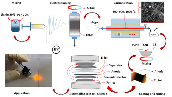
2. Experimental
2.1. Materials and Chemicals
2.2. Activated Carbon Production
2.3. Characterization
2.4. Electrochemical Measurements
2.4.1. Preparation of Electrodes
2.4.2. Electrochemical Measurements
3. Results and Discussion
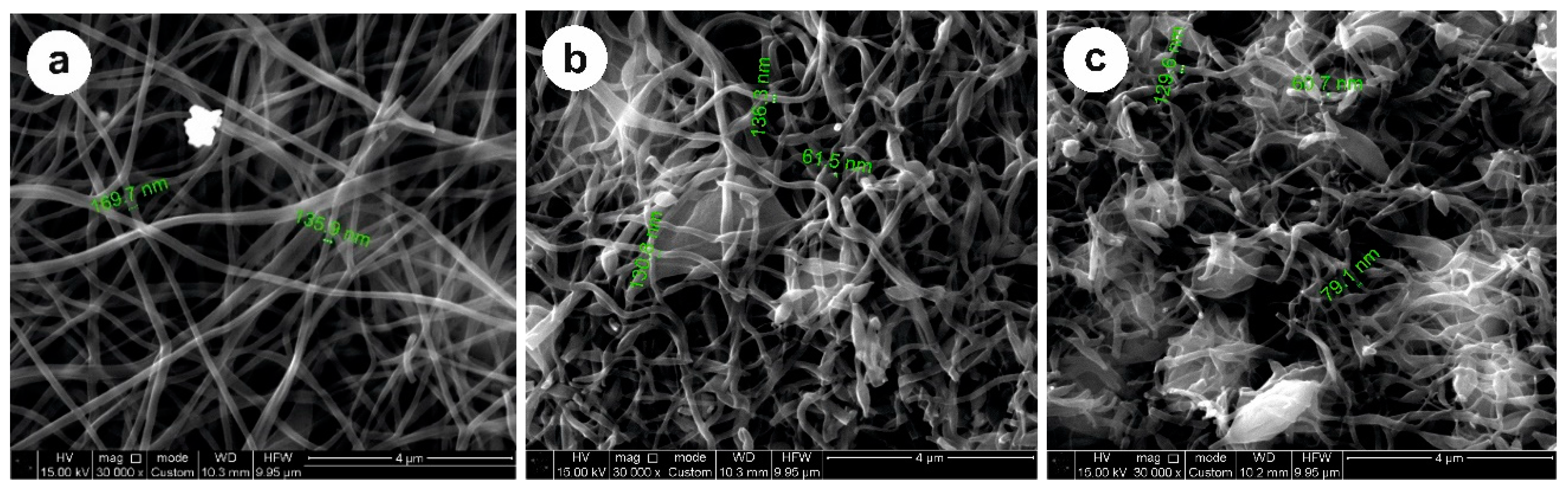
3.1. Activated Carbon Surface Characterization
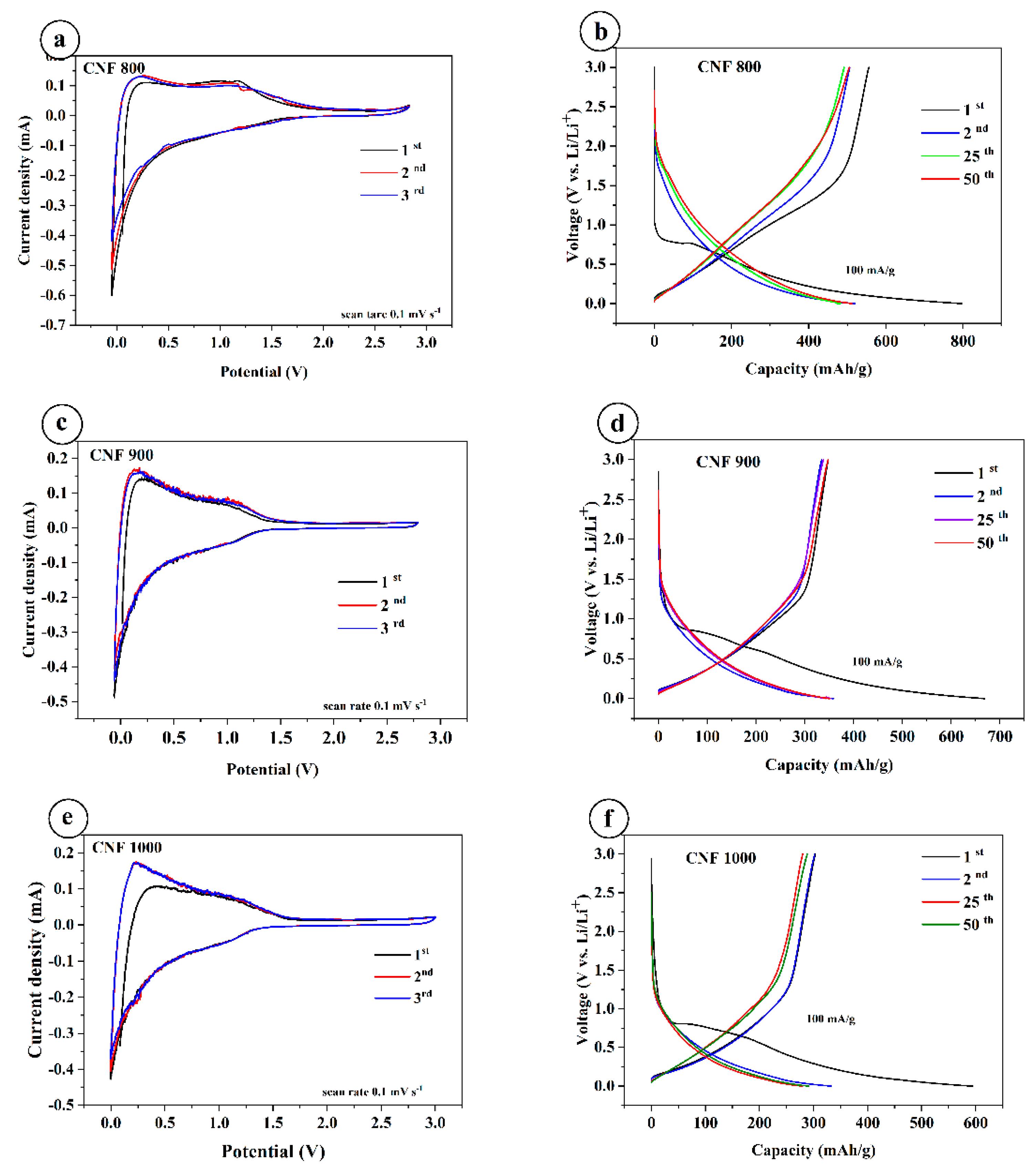
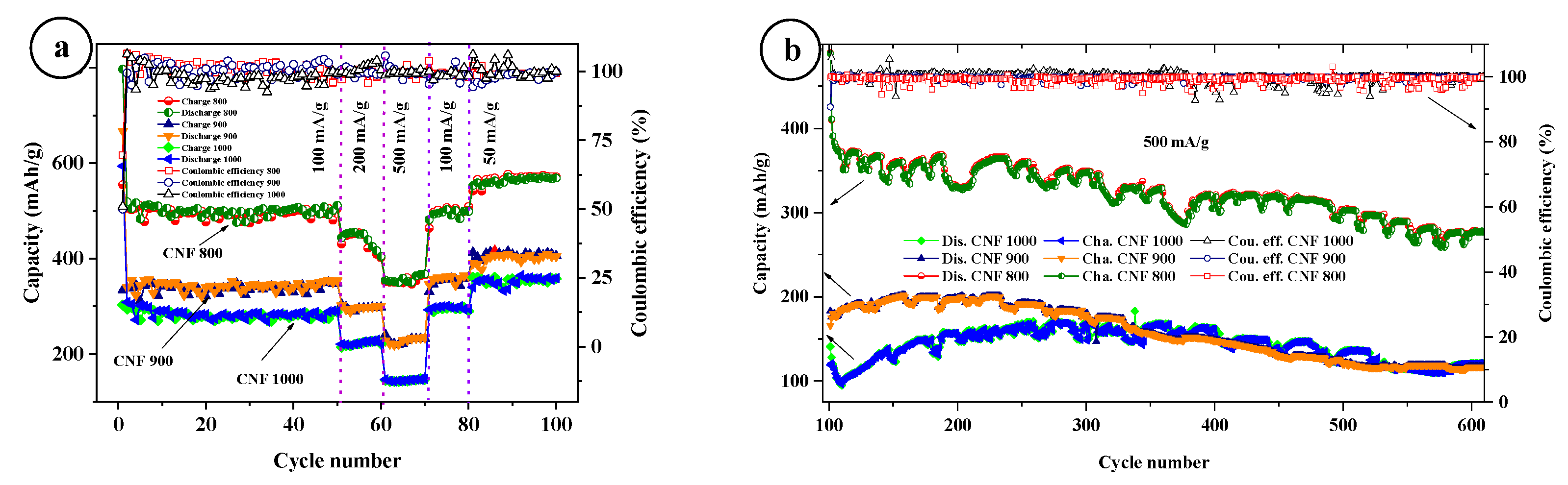
3.2. Electrochemical Characterization
4. Conclusions
Author Contributions
Funding
Data Availability Statement
Acknowledgments
Conflicts of Interest
References
- Zheng, S.; Xue, H.; Pang, H. Supercapacitors based on metal coordination materials. Coord. Chem. Rev. 2018, 373, 2–21. [Google Scholar] [CrossRef]
- Liu, C.; Yan, X.; Hu, F.; Gao, G.; Wu, G.; Yang, X. Toward Superior Capacitive Energy Storage: Recent Advances in Pore Engineering for Dense Electrodes. Adv. Mater. 2018, 30, e1705713. [Google Scholar] [CrossRef] [PubMed]
- Wu, P.; Cheng, S.; Yang, L.; Lin, Z.; Gui, X.; Ou, X.; Zhou, J.; Yao, M.; Wang, M.; Zhu, Y.; et al. Synthesis and characterization of self-standing and hghly fexible d-MnO2@CNTs/CNTs composite films for direct use of supercapacitor electrodes. ACS Appl. Mater. Interfaces 2016, 8, 23721–23728. [Google Scholar] [CrossRef] [PubMed]
- Liu, J.; Zheng, M.; Shi, X.; Zeng, H.; Xia, H. Amorphous FeOOH Quantum Dots Assembled Mesoporous Film Anchored on Graphene Nanosheets with Superior Electrochemical Performance for Supercapacitors. Adv. Funct. Mater. 2015, 26, 919–930. [Google Scholar] [CrossRef]
- Li, Y.; Xu, J.; Feng, T.; Yao, Q.; Xie, J.; Xia, H. Fe2O3Nanoneedles on Ultrafine Nickel Nanotube Arrays as Efficient Anode for High-Performance Asymmetric Supercapacitors. Adv. Funct. Mater. 2017, 27, 1606728. [Google Scholar] [CrossRef]
- Zhang, C.; Yin, H.; Han, M.; Dai, Z.; Pang, H.; Zheng, Y.; Lan, Y.-Q.; Bao, J.; Zhu, J. Two-Dimensional Tin Selenide Nanostructures for Flexible All-Solid-State Supercapacitors. ACS Nano 2014, 8, 3761–3770. [Google Scholar] [CrossRef]
- Wu, J.; Park, H.W.; Yu, A.; Higgins, D.; Chen, Z. Facile Synthesis and Evaluation of Nanofibrous Iron−Carbon Based Non-Precious Oxygen Reduction Reaction Catalysts for Li−O2 Battery Applications. J. Phys. Chem. C 2012, 116, 9427–9432. [Google Scholar] [CrossRef]
- Palacín, M.R.; de Guibert, A. Why do batteries fail? Science 2016, 351, 1253292. [Google Scholar] [CrossRef]
- El Kharbachi, A.; Zavorotynska, O.; Latroche, M.; Cuevas, F.; Yartys, V.; Fichtner, M. Exploits, advances and challenges benefiting beyond Li-ion battery technologies. J. Alloy. Compd. 2020, 817, 153261. [Google Scholar] [CrossRef]
- Tiwari, A.P.; Chae, S.-H.; Ojha, G.P.; Dahal, B.; Mukhiya, T.; Lee, M.; Chhetri, K.; Kim, T.; Kim, H.-Y. Three-dimensional porous carbonaceous network with in-situ entrapped metallic cobalt for supercapacitor application. J. Colloid Interface Sci. 2019, 553, 622–630. [Google Scholar] [CrossRef]
- Wang, L.; Zhang, G.; Zhang, X.; Shi, H.; Zeng, W.; Zhang, H.; Liu, Q.; Li, C.; Liu, Q.; Duan, H. Porous ultrathin carbon nanobubbles formed carbon nanofiber webs for high-performance flexible supercapacitors. J. Mater. Chem. A 2017, 5, 14801–14810. [Google Scholar] [CrossRef]
- Mukhiya, T.; Dahal, B.; Ojha, G.P.; Kang, D.; Kim, T.; Chae, S.-H.; Muthurasu, A.; Kim, H.Y. Engineering nanohaired 3D cobalt hydroxide wheels in electrospun carbon nanofibers for high-performance supercapacitors. Chem. Eng. J. 2019, 361, 1225–1234. [Google Scholar] [CrossRef]
- Morris, E.A.; Weisenberger, M.C.; Bradley, S.B.; Abdallah, M.G.; Mecham, S.J.; Pisipati, P.; McGrath, J.E. Synthesis, spinning, and properties of very high molecular weight poly(acrylonitrile-co-methyl acrylate) for high performance precursors for carbon fiber. Polymer 2014, 55, 6471–6482. [Google Scholar] [CrossRef]
- Inagaki, M.; Yang, Y.; Kang, F. Carbon Nanofibers Prepared via Electrospinning. Adv. Mater. 2012, 24, 2547–2566. [Google Scholar] [CrossRef]
- Zhang, B.; Kang, F.; Tarascon, J.-M.; Kim, J.-K. Recent advances in electrospun carbon nanofibers and their application in electrochemical energy storage. Prog. Mater. Sci. 2016, 76, 319–380. [Google Scholar] [CrossRef]
- Xue, J.; Wu, T.; Dai, Y.; Xia, Y. Electrospinning and Electrospun Nanofibers: Methods, Materials, and Applications. Chem. Rev. 2019, 119, 5298–5415. [Google Scholar] [CrossRef]
- Zhang, W.-J. A review of the electrochemical performance of alloy anodes for lithium-ion batteries. J. Power Sources 2011, 196, 13–24. [Google Scholar] [CrossRef]
- Wang, H.; Abe, T.; Maruyama, S.; Iriyama, Y.; Ogumi, Z.; Yoshikawa, K. Graphitized Carbon Nanobeads with an Onion Texture as a Lithium-Ion Battery Negative Electrode for High-Rate Use. Adv. Mater. 2005, 17, 2857–2860. [Google Scholar] [CrossRef]
- Zhang, K.; Li, X.; Liang, J.; Zhu, Y.; Hu, L.; Cheng, Q.; Guo, C.; Lin, N.; Qian, Y. Nitrogen-doped porous interconnected double-shelled hollow carbon spheres with high capacity for lithium ion batteries and sodium ion batteries. Electrochim. Acta 2015, 155, 174–182. [Google Scholar] [CrossRef]
- Gao, H.; Hou, F.; Zheng, X.; Liu, J.; Guo, A.; Yang, D.; Gong, Y. Electrochemical property studies of carbon nanotube films fabricated by CVD method as anode materials for lithium-ion battery applications. Vacuum 2015, 112, 1–4. [Google Scholar] [CrossRef]
- Yoon, S.; Lee, S.; Kim, S.; Park, K.-W.; Cho, D.; Jeong, Y. Carbon nanotube film anodes for flexible lithium ion batteries. J. Power Sources 2015, 279, 495–501. [Google Scholar] [CrossRef]
- Yu, Y.; Yang, Q.; Teng, D.; Yang, X.; Ryu, S. Reticular Sn nanoparticle-dispersed PAN-based carbon nanofibers for anode material in rechargeable lithium-ion batteries. Electrochim. Acta 2009, 55, 521. [Google Scholar] [CrossRef]
- Yoon, S.-H.; Park, C.-W.; Yang, H.; Korai, Y.; Mochida, I.; Baker, R.; Rodriguez, N.M. Novel carbon nanofibers of high graphitization as anodic materials for lithium ion secondary batteries. Carbon 2004, 42, 21–32. [Google Scholar] [CrossRef]
- Yan, X.; Teng, D.; Jia, X.; Yu, Y.; Yang, X. Improving the cyclability and rate capability of carbon nanofiber anodes through in-site generation of SiOx-rich overlayers. Electrochim. Acta 2013, 108, 196. [Google Scholar] [CrossRef]
- Yue, H.; Li, F.; Yang, Z.; Tang, J.; Li, X.; He, D. Nitrogen-doped carbon nanofibers as anode material for high-capacity and binder-free lithium ion battery. Mater. Lett. 2014, 120, 39–42. [Google Scholar] [CrossRef]
- Cai, D.; Wang, S.; Ding, L.; Lian, P.; Zhang, S.; Peng, F.; Wang, H. Superior cycle stability of graphene nanosheets prepared by freeze-drying process as anodes for lithium-ion batteries. J. Power Sources 2014, 254, 198–203. [Google Scholar] [CrossRef]
- Zhan, Y.; Zhang, B.; Cao, L.; Wu, X.; Lin, Z.; Yu, X.; Zhang, X.; Zeng, D.; Xie, F.; Zhang, W.; et al. Iodine doped graphene as anode material for lithium ion battery. Carbon 2015, 94, 1–8. [Google Scholar] [CrossRef]
- Zhang, J.; Hu, Y.-S.; Tessonnier, J.-P.; Weinberg, G.; Maier, J.; Schlögl, R.; Su, D.S. CNFs@CNTs: Superior Carbon for Electrochemical Energy Storage. Adv. Mater. 2008, 20, 1450–1455. [Google Scholar] [CrossRef]
- Zhang, X.; Han, S.; Fan, C.; Li, L.; Zhang, W. Hard carbon enveloped with graphene networks as lithium ion battery anode. Mater. Lett. 2015, 138, 259–261. [Google Scholar] [CrossRef]
- Zou, G.; Zhang, D.; Dong, C.; Li, H.; Xiong, K.; Fei, L.; Qian, Y. Carbon nanofibers: Synthesis, characterization, and electrochemical properties. Carbon 2006, 44, 828–832. [Google Scholar] [CrossRef]
- Kim, C.; Ngoc, B.T.N.; Yang, K.S.; Kojima, M.; Kim, Y.A.; Kim, Y.J.; Endo, M.; Yang, S.C. Fabrication of Electrospinning-Derived Carbon Nanofiber Webs for the Anode Material of Lithium-Ion Secondary Batteries. Adv. Funct. Mater. 2006, 16, 2393–2397. [Google Scholar] [CrossRef]
- Chen, C.; Agrawal, R.; Hao, Y.; Wang, C. Activated Carbon Nanofibers as High Capacity Anodes for Lithium-Ion Batteries. ECS J. Solid State Sci. Technol. 2013, 2, M3074–M3077. [Google Scholar] [CrossRef]
- Tao, L.; Huang, Y.; Yang, X.; Zheng, Y.; Liu, C.; Di, M.; Zheng, Z. Flexible anode materials for lithium-ion batteries derived from waste biomass-based carbon nanofibers: I. Effect of carbonization temperature. RSC Adv. 2018, 8, 7102–7109. [Google Scholar] [CrossRef]
- Ji, L.; Zhang, X. Manganese oxide nanoparticle-loaded porous carbon nanofibers as anode materials for high-performance lithium-ion batteries. Electrochem. Commun. 2009, 11, 795–798. [Google Scholar] [CrossRef]
- Peng, Y.-T.; Lo, C.-T. Effect of Microstructure and Morphology of Electrospun Ultra-Small Carbon Nanofibers on Anode Performances for Lithium Ion Batteries. J. Electrochem. Soc. 2015, 162, A1085–A1093. [Google Scholar] [CrossRef]
- Lee, Y.-S.; Ryu, K.-S. Study of the lithium diffusion properties and high rate performance of TiNb6O17 as an anode in lithium secondary battery. Sci. Rep. 2017, 7, 16617. [Google Scholar] [CrossRef] [PubMed]


| Samples | {002} | {100} | ||
|---|---|---|---|---|
| 2 θ | D Spacings, nm | 2 θ | D Spacings, nm | |
| CNF 800 | 24.7251 | 0.356245 | 43.6751 | 0.207083 |
| CNF 900 | 24.9251 | 0.357655 | 43.8751 | 0.26185 |
| CNF 1000 | 24.9751 | 0.35979 | 44.2251 | 0.204634 |
Publisher’s Note: MDPI stays neutral with regard to jurisdictional claims in published maps and institutional affiliations. |
© 2022 by the authors. Licensee MDPI, Basel, Switzerland. This article is an open access article distributed under the terms and conditions of the Creative Commons Attribution (CC BY) license (https://creativecommons.org/licenses/by/4.0/).
Share and Cite
Nazhipkyzy, M.; Maltay, A.B.; Askaruly, K.; Assylkhanova, D.D.; Seitkazinova, A.R.; Mansurov, Z.A. Biomass-Derived Porous Carbon Materials for Li-Ion Battery. Nanomaterials 2022, 12, 3710. https://doi.org/10.3390/nano12203710
Nazhipkyzy M, Maltay AB, Askaruly K, Assylkhanova DD, Seitkazinova AR, Mansurov ZA. Biomass-Derived Porous Carbon Materials for Li-Ion Battery. Nanomaterials. 2022; 12(20):3710. https://doi.org/10.3390/nano12203710
Chicago/Turabian StyleNazhipkyzy, Meruyert, Anar B. Maltay, Kydyr Askaruly, Dana D. Assylkhanova, Aigerim R. Seitkazinova, and Zulkhair A. Mansurov. 2022. "Biomass-Derived Porous Carbon Materials for Li-Ion Battery" Nanomaterials 12, no. 20: 3710. https://doi.org/10.3390/nano12203710
APA StyleNazhipkyzy, M., Maltay, A. B., Askaruly, K., Assylkhanova, D. D., Seitkazinova, A. R., & Mansurov, Z. A. (2022). Biomass-Derived Porous Carbon Materials for Li-Ion Battery. Nanomaterials, 12(20), 3710. https://doi.org/10.3390/nano12203710