Article

Quasi-Solid-State Lithium-Sulfur Batteries Assembled by Composite Polymer Electrolyte and Nitrogen Doped Porous Carbon Fiber Composite Cathode

Guangxi Key Laboratory of Automobile Components and Vehicle Technology, Guangxi University of Science and Technology, Liuzhou 545006, China
*
Authors to whom correspondence should be addressed.
Nanomaterials 2022, 12(15), 2614; https://doi.org/10.3390/nano12152614
Submission received: 30 June 2022 / Revised: 25 July 2022 / Accepted: 25 July 2022 / Published: 29 July 2022
(This article belongs to the Special Issue Advances in Nano-Electrochemical Materials and Devices)

Abstract

:
Solid-state lithium sulfur batteries are becoming a breakthrough technology for energy storage systems due to their low cost of sulfur, high energy density and high level of safety. However, its commercial application has been limited by the poor ionic conductivity and sulfur shuttle effect. In this paper, a nitrogen-doped porous carbon fiber (NPCNF) active material was prepared by template method as a sulfur-host of the positive sulfur electrode. The morphology was nano fiber-like and enabled high sulfur content (62.9 wt%). A solid electrolyte membrane (PVDF/LiClO4/LATP) containing polyvinylidene fluoride (PVDF) and lithium aluminum titanium phosphate (Li1.3Al0.3Ti1.7(PO4)3) was prepared by pouring and the thermosetting method. The ionic conductivity of PVDF/LiClO4/LATP was 8.07 × 10⁻⁵ S cm−1 at 25 °C. The assembled battery showed good electrochemical performance. At 25 °C and 0.5 C, the first discharge specific capacity was 620.52 mAh g−1. After 500 cycles, the capacity decay rate of each cycle was only 0.139%. The synergistic effect between the composite solid electrolyte and the nitrogen-doped porous carbon fiber composite sulfur anode studied in this paper may reveal new approaches for improving the cycling performance of a solid-state lithium-sulfur battery.

1. Introduction

With the increasing energy demand for energy storage equipment in the current market, traditional lithium-ion batteries cannot meet the requirements due to low energy density, poor safety and high cost [1,2]. Therefore, it is imperative to develop and research a new battery system with high specific energy and high safety. The theoretical specific capacity and theoretical specific energy of lithium-sulfur battery can reach 1675 mAh g−1, 2600 wh kg−1. What’s more, sulfur has obvious advantages in environmental protection, acquisition cost, and so on. It is considered to be the most promising next-generation new energy storage system [3,4]. However, the commercialization of lithium-sulfur batteries still faces some problems [5,6]. Firstly, liquid electrolytes have the safety problem of inflammability and the possibility of explosion, and the lithium dendrite grown from the negative electrode pierces the diaphragm, leading to short circuit [7,8]. Secondly, sulfur has poor electrical conductivity and low utilization rate of active materials. The “shuttle effect” caused by polysulfide dissolution leads to low capacity and coulomb efficiency [1,9].
In order to solve the above problems, more and more attention has been paid to solid-state lithium-sulfur batteries [10,11]. On the one hand, the cathode side requires a high conductivity material to improve contact with low conductivity S. Carbon materials have high electrical conductivity, high specific surface area and excellent mechanical properties, which can provide a conductive network for sulfur and discharge products (Li2S) and improve the electrochemical performance of sulfur cathodes [12]. In addition, the introduction of nitrogen doping cannot only significantly improve the electrical conductivity of carbon materials, but also introduce active sites on the surface of carbon materials [13]. Therefore, nitrogen-doped carbon materials can be used in lithium-sulfur batteries as active materials with high electronic conductivity and strong physical and chemical adsorption. On the other hand, there is no solid electrolyte that can meet all the requirements, such as high ionic conductivity at room temperature, a wide electrochemical stability window, good mechanical properties, etc. [14,15,16,17]. The advantages and disadvantages of different solid-state electrolytes are integrated by using composite electrolytes, which provides a new idea for further study of solid-state lithium-sulfur batteries. Polyoxyethylene (PEO) and polyvinylidene fluoride (PVDF) are common polymer electrolyte substrates [18,19,20]. Currently, polyoxyethylene (PEO) has been widely studied in lithium-sulfur batteries, but its ionic conductivity is low at room temperature, and it can only show good ionic conductivity in the amorphous state of 60~90 °C [21]. Compared with PEO, the PVDF electrolyte has better mechanical strength and a higher melting point. Adding inorganic filler to a polymer electrolyte to form CPEs can effectively improve ionic conductivity and lithium-ion transference number. Common inorganic electrolytes include NASICON type, Li10GeP2S12(LGPS) type, LixPON type, Li2S-P2S5 type and Li7La3Zr2O12 (LLZO) type [22,23,24,25]. Lithium titanium aluminum phosphate (LATP) is a glass ceramic material with NASICON type three-dimensional network structure, which has the advantages of high mechanical strength, high ionic conductivity, high temperature stability and stability to air and water [26,27]. However, the application of LATP as an electrolyte in batteries is limited by its large interfacial impedance and side effects. By adding a certain amount of nano-scale ceramic materials into the polymer electrolyte, the composite polymer-ceramic electrolyte (CPEs) formed has lower interfacial resistance and higher ionic conductivity [28,29]. It can inhibit the formation of lithium dendrite and the shuttle effect of polysulfide and can be effectively applied to solid-state lithium-sulfur batteries.
In this paper, a nitrogen-doped porous carbon fiber active material (NPCNF) with a microporous structure and nanofiber shape was prepared via template method. The NPCNF/S electrode exhibits excellent performance due to the better electrical conductivity and strong physical and chemical adsorption of carbon and nitrogen doped materials. A PVDF/LiClO4/LATP composite solid electrolyte (CPEs) was prepared, which combined the advantages of inorganic electrolytes and polymer electrolytes. It has the characteristics of a wide electrochemical window, high ionic conductivity and stable mechanical properties at room temperature. The assembled quasi-solid lithium sulfur battery was tested at 25 °C and had excellent performance. This study proves that the long cycle performance of a solid-state lithium-sulfur battery is improved at a large magnification rate, which provides ideas for subsequent research.

2. Materials and Methods

2.1. Materials

The raw materials included PEO-PPO-PEO (P123) (99%, Aladdin, Shanghai, China), C8H2OO4Si (99%, Aladdin, Shanghai, China), HCl (98%, Aladdin, Shanghai, China), C2H4N4 (99%, Aladdin, Shanghai, China), HF (40%, Aladdin, Shanghai, China), S (99%, Aladdin, Shanghai, China), polyvinylidene fluoride (PVDF) (Mw = 600,000, Macklin, Shanghai, China), lithium bisimide (LiClO4) (99.99% purity, Aladdin, Shanghai, China), Li1.3Al0.3Ti1.7(PO4)3 (99.99% purity, Macklin, Shanghai, China).

2.2. Preparation of the NPCNF/S Composite

We dissolved 1 g PEO-PPO-PEO (P123) in 6 mL C8H2OO4Si under magnetic stirring. Then, we added 32 mL ethanol and 0.583 mL concentrated hydrochloric acid (HCl, 37%) to the solution. After adding 4 mL of deionized water, wefully stirred the hydrolysis for 2 h. Adding 2.8 g dicyandiamide (DCDA) as carbon source and nitrogen source, the semi-solid colloid was obtained by stirring and drying at 80 °C. The powder was dried overnight at 80 °C to obtain a white powder; then, we calcined N2 in a tubular furnace at 1000 °C for 60 min at a heating rate of 3 °C min−1. After cooling to room temperature, the sintered powder was poured into 5%HF solution to clean the template. Fully cleaned samples were dried at 60 °C for 12 h to obtain the final product NPCNF. The NPCNF was mixed with elemental S at a mass ratio of 1:2 and calcined at 155 °C for 12 h in a tube furnace under a nitrogen atmosphere. Cooling to room temperature to obtain NPCNF/S.

2.3. Preparation of the Composite Solid Electrolyte Membrane (CPEs)

PVDF, LATP and LiClO4 powders were vacuum-dried at 60 °C for 24 h. PVDF, LATP, LiClO4 and DMF were weighed at the mass ratio of 10:1:0.124:80. PVDF was dissolved in 40 mL DMF and stirred at 55 °C for 1 h to form a transparent viscous solution. LATP and LiClO4 were added and stirred for 5~6 h. Finally, the mixed solution was cast into a polytetrafluoroethylene mold and vacuum dried at 60 °C for 24~72 h to obtain flexible electrolyte films with ceramic/polymer composites

2.4. Battery Assembly

NPCNF/S, conducting carbon and polyvinylidene fluoride (PVDF), were dissolved in N-methylpyrrolidone (NMP) at a mass ratio of 7:2:1 and stirred to a obtain uniform slurry. The slurry was coated on aluminum foil and dried in a vacuum drying oven for 12 h. The composite electrolyte was cut into discs with a diameter of 18 mm. The 2025-coin cells were assembled and tested. We then added two drops of electrolyte. The electrolyte was 1.0 mol LiTFSI in DOL:DME = 1:1 vol% with 1.0 wt% LiNO3.

2.5. Characterization

Via X-ray diffraction (XRD, D8-Advance, Bruker, Germany), the material phase was analyzed by measuring the diffraction data in the range of 10~90°. Via thermogravimetric analysis (TGA) measurement in air atmosphere temperature under the condition of 10 °Cmin−1, we performed an analysis of material quality, along with the change of temperature. The cathode material was tested via Raman spectroscopy (XploRA PLUS, HORIBA, France) under a 523 nm Raman microscope. The microscopic morphology of the sample was characterized via scanning electron microscope (SEM, Sigma04-55, ZEISS, Germany). The composition and valence of solid electrolyte elements were determined by X-ray photoelectron spectroscopy (XPS, K-alpha, Thermo, America) at 5 kV.

2.6. Electrochemical Measurements

The timing current of lithium symmetric battery was tested at a voltage of 0.5 mV, lasting 4000 s, and the formula was as follows:
t L i + = I s ( Δ V I 0 R 0 ) / I 0 ( Δ V I s R s )
The lithium-ion transfer rate (tLi+) can be obtained. I0 and Is are current values after DC polarization starts and stabilizes, R0 and Rs are the impedance values before and after the DC polarization, and ΔV is the value of the voltage applied to both ends of the battery.
For the ionic conductivity test, battery assembly used SS as a symmetrical battery and electrochemical impedance test together to calculate the ionic conductivity. The frequency range of impedance test is 0.1~106 Hz.
σ = L / S × R
where σ represents the ionic conductivity, L is the thickness of electrolyte, S represents the contact area between electrolyte and test electrode (SS) and R is the impedance value of battery electrolyte measured by EIS. The battery test system (CT-400, Neware, Hong Kong, China) performed constant current charge–discharge cycle tests between 1.5 and 3 V. At 25 °C, the electrochemical workstation (DH-7000, Donghua, Shanghai, China) was used for cyclic voltammetry (CV) test at 1.5~3 V and 0.2 mV s−1. Linear sweep voltammetry (LSV) was used to perform electrochemical window tests at 2~6 V at a scanning rate of 0.1 mV s−1.

3. Results

Figure 1 shows the manufacturing process of CPEs and NPCNF/S positive poles. The NPCNF material was prepared via the etching template method. Its unique hole structure increased the specific surface area of the material, and it could load more elemental sulfur. After mixing with S, the positive electrode sheet was obtained after the slurry coating. The polymer, lithium salt and inorganic electrolyte were fully dissolved in the mixed solution, and the nanoscale LATP was uniformly combined with PVDF to obtain CPEs.
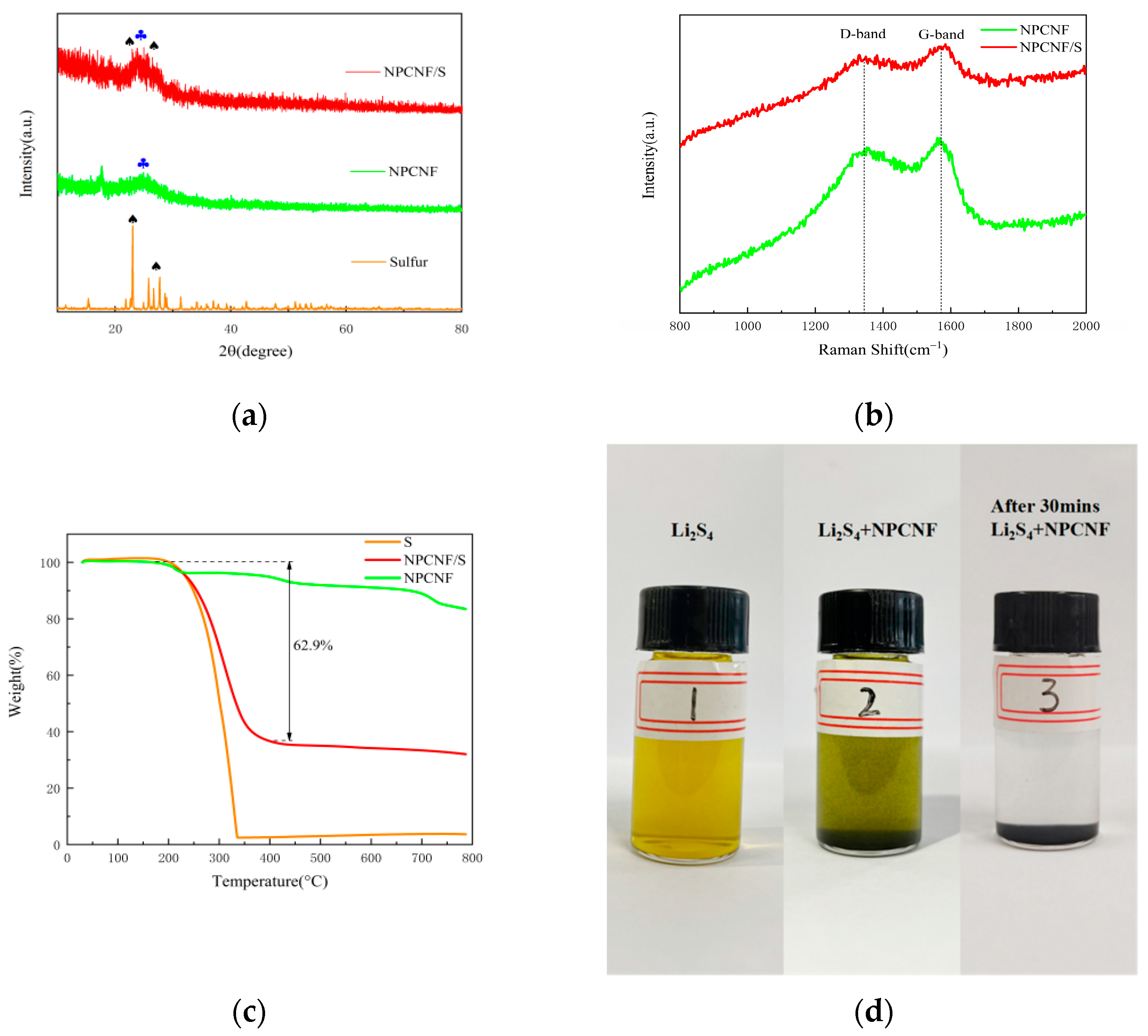
XRD patterns of NPCNF and NPCNF/S are shown in Figure 2a. NPCNF/S has an obvious diffraction peak corresponding to elemental S at 23.04°. There is a diffraction peak at 24.8° of NPCNF corresponding to the (002) plane of graphite carbon, which proves that a certain amount of graphite amorphous carbon is formed in the material. The diffraction peak at two places indicates that the characteristics of elemental S and NPCNF are retained in NPCNF/S. NPCNF/S, compared with the diffraction peak of sulfur, was reduced greatly, and this is due to the large amounts of S fully penetrated into the microporous structure of the carbon fiber material [30]. The corresponding morphology can be observed in the SEM figure (Figure 3c,d). Raman spectroscopy was used to test NPCNF and NPCNF/S, as shown in Figure 2b. The D band and G band intensity ratios of NPCNF and NPCNF/S are 1.04 and 1.03, respectively. The differences were small, indicating that the introduction of sulfur particles did not change the graphitization degree of NPCNF. The ID/G values are all greater than 1, indicating that the active material has a high degree of graphite carbonization and good conductivity [31]. In order to determine the sulfur content of the NPCNF/S sample, TGA measurement was carried out, as shown in Figure 2c. The mass change of the sample was measured when the temperature was raised to 800 °C at a heating rate of 10 °C min−1 in a nitrogen flow. It can be seen that there was about a 17 wt% amount of weight loss when NPCNF rose to 800 °C, and the elemental sulfur rapidly sublimated to complete disappearance at 250~350 °C. The sulfur content of the NPCNF/S sample is about 62.9 wt%. The sulfur loading and content of the cathode is 0.38 mg cm−2. An experiment on adsorption of polysulfide lithium was carried out using NPCNF, as shown in Figure 2d. Firstly, we added Li2S4 to form a light-yellow solution (Bottle No. 1); 10 mg of NPCNF was added as the No. 2 solution. After standing for 30 min, a clear and transparent liquid was formed in bottle No.3. The pore structure of the NPCNF material had an obvious adsorption and anchoring effect on Li2S4, which results in an inhibiting “shuttle effect” of lithium-sulfur batteries.
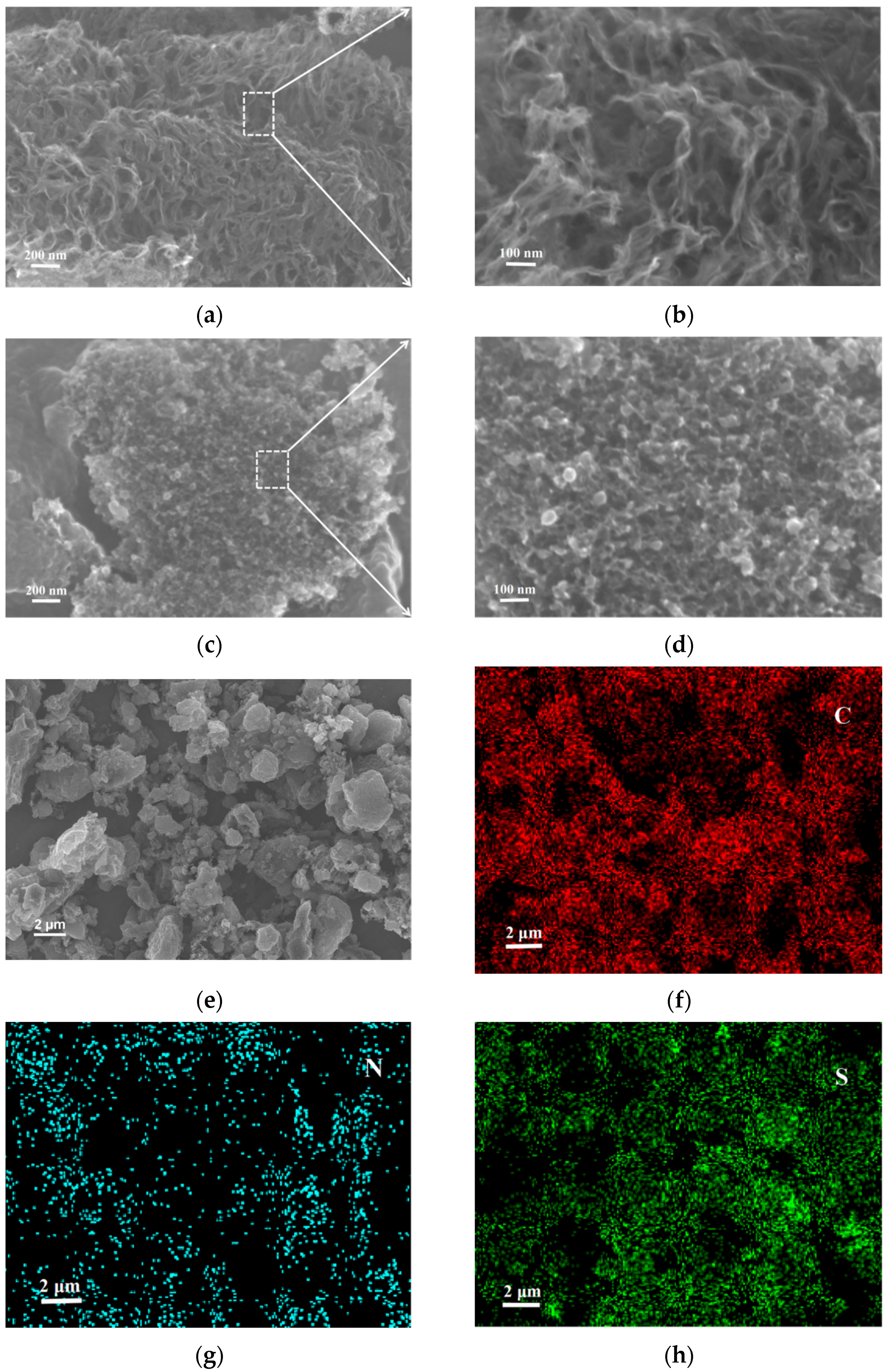
SEM characterization tests were conducted for NPCNF and NPCNF/S, as shown in Figure 3. Figure 3a,b shows that the surface of NPCNF presents an irregular reticular structure resembling nanofiber. After being fully etched by the HF solution, an EDS test analysis of NPCNF shows that no Si element was found in the material, and nano-SiO2 particles generated by tetraethyl orthosilicate hydrolysis were cleaned and removed. The holes leftover increase the specific surface area of the material, which is conducive to the load of S and sulfide in the positive electrode. At the same time, polysulfide can be adsorbed through physical action to provide channels for ion transfer in the battery. After loading S, the sample changes from a nanofiber to porous mesoporous structure, but the original carbon fiber conductive network still remains, as shown in Figure 3c,d. This unique porous mesoporous structure anchors polysulfide, which inhibits the “shuttle effect” and improves the cycling performance of the battery [32]. Figure 3e–h shows the EDS test analysis element map in the specified region of NPCNF/S, where C,N,S elements are evenly distributed, proving the uniformity of material doping.
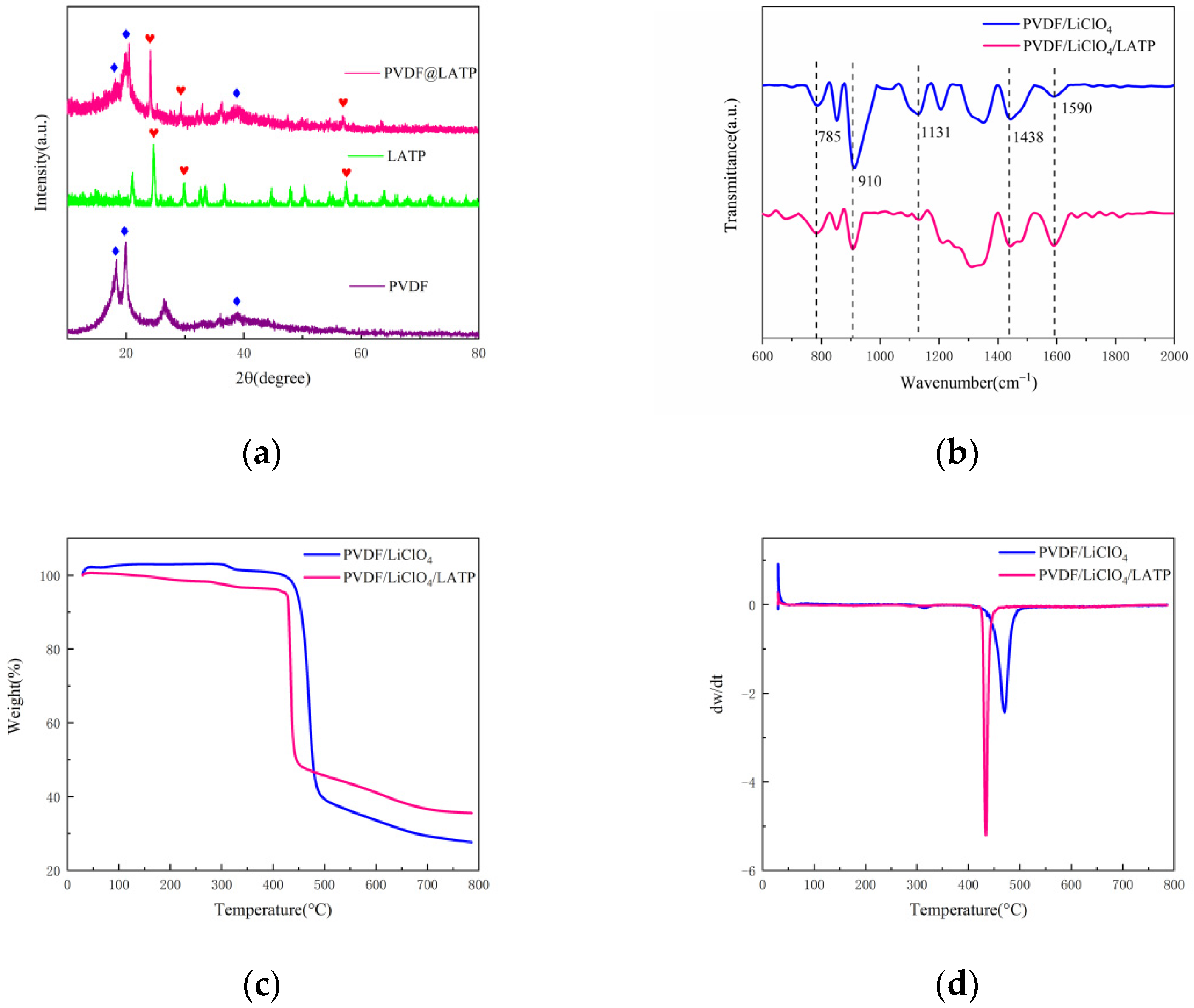
The XRD results of CPEs can be seen in Figure 4a, 24.2° and 20°, respectively, correspond to characteristic peaks of LATP and PVDF, and another wide peak appears at 38.9°, indicating that PVDF is dominated by γ phase [33]. The characteristic peaks of PVDF and LATP were retained in the samples, indicating that the PVDF and LATP did not combine with each other, but kept their respective characteristics together. Figure 4b shows that the absorption peak of PVDF/LiClO4 complex at 785,910,1131,1438 and 1590 cm−1 did not shift with the addition of LATP. The change of peak value at 910 cm−1 corresponds to the out-of-plane bending of C-H bond, and the change of peak value at 1590 cm−1 is the stretching vibration of C-C bond and C=O, indicating that the addition of LATP is conducive to lithium-ion migration [34]. The TGA tests were conducted for PVDF/LiClO4 and PVDF/LiClO4/LATP. As shown in Figure 4c, rapid weight loss occurred at 400~500 °C. It can be seen from Figure 4d that the temperature of rapid sublimation loss of PVDF/LiClO4 and PVDF/LiClO4/LATP were 471 °C and 433 °C. The weight loss rate of PVDF/LiClO4/LATP was lower than that of PVDF/LiClO4, indicating that the addition of LATP improved the thermal stability of CPEs.
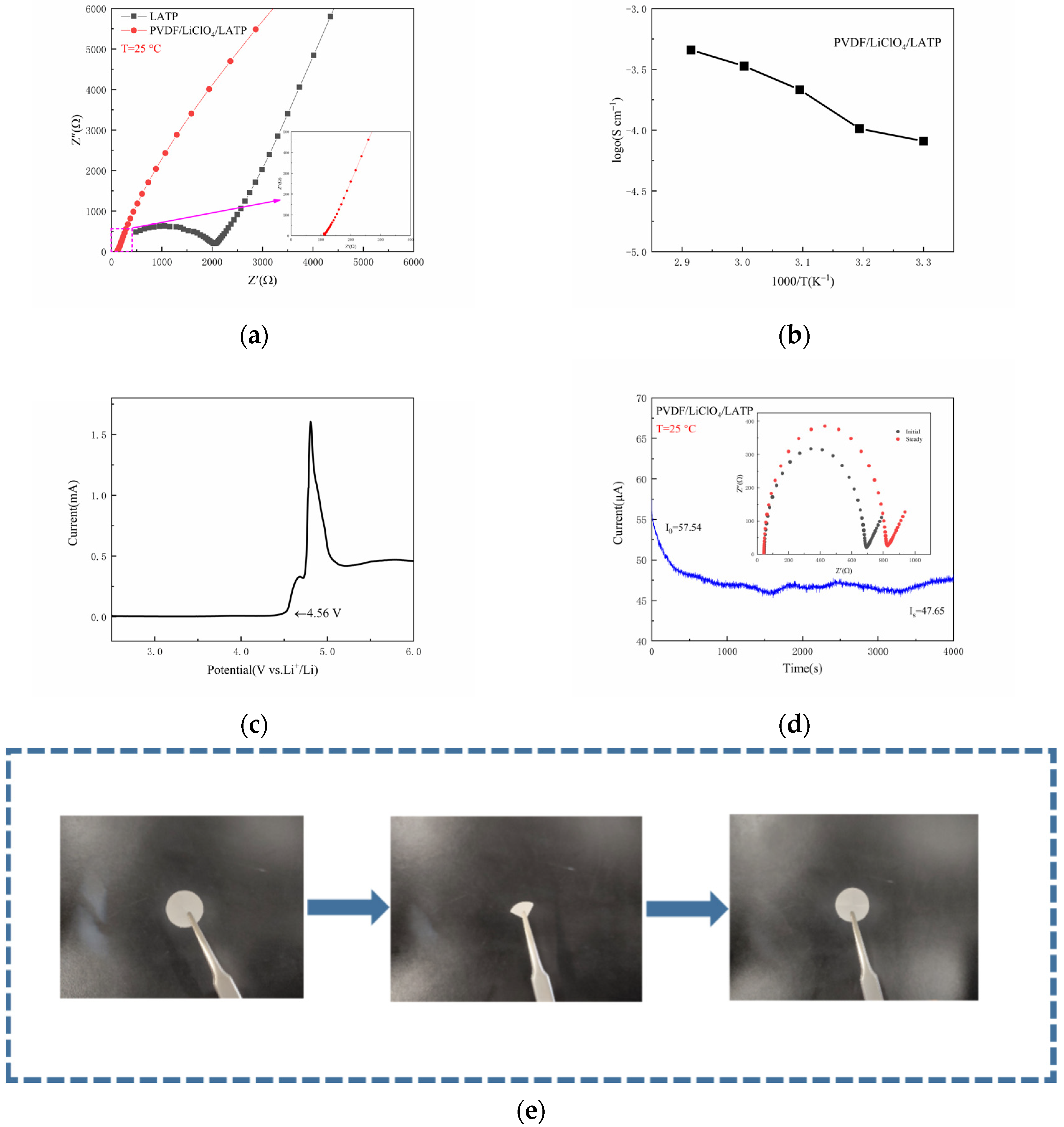
See Figure 5a for measuring the EIS of CPEs and LATP under 25 °C. It is obvious that the impedance of electrolyte was greatly reduced, which was due to the better flexibility of the membrane made by the combination of PVDF and LATP, as shown in Figure 5e, greatly reducing the interface impedance. The ionic conductivity was at 25 °C is 8.07 × 10⁻⁵ S cm−1. Figure 5b shows the Arrhenius diagram of CPEs. With the increase of temperature, the ionic conductivity also increased correspondingly. The increase of temperature promoted the expansion of the polymer and generated free volume in the polymer, which enhanced the segment movement of the polymer and increased the ionic conductivity [35]. The electrochemical window is also an indicator to evaluate the performance of CPEs. Therefore, linear sweep voltammetry (LSV) was used to characterize the electrochemical window. As shown in Figure 5c, the composite solid electrolyte membrane could withstand a voltage of 4.56 V, which is more than sufficient for Li-S batteries. Figure 5d shows the initial impedance spectrum and the impedance spectrum and timing current curve after polarization. The lithium-ion transfer rate of CPEs was calculated to be 0.77. Compared with a traditional liquid electrolyte (tLi+ < 0.5) [36], the addition of LATP improved the lithium-ion transfer rate and made the CPEs have better performance. A high lithium-ion transfer rate can generally reduce the concentration of movable anions in CPEs, thus reducing electrode polarization and the accompanying side reactions [37].
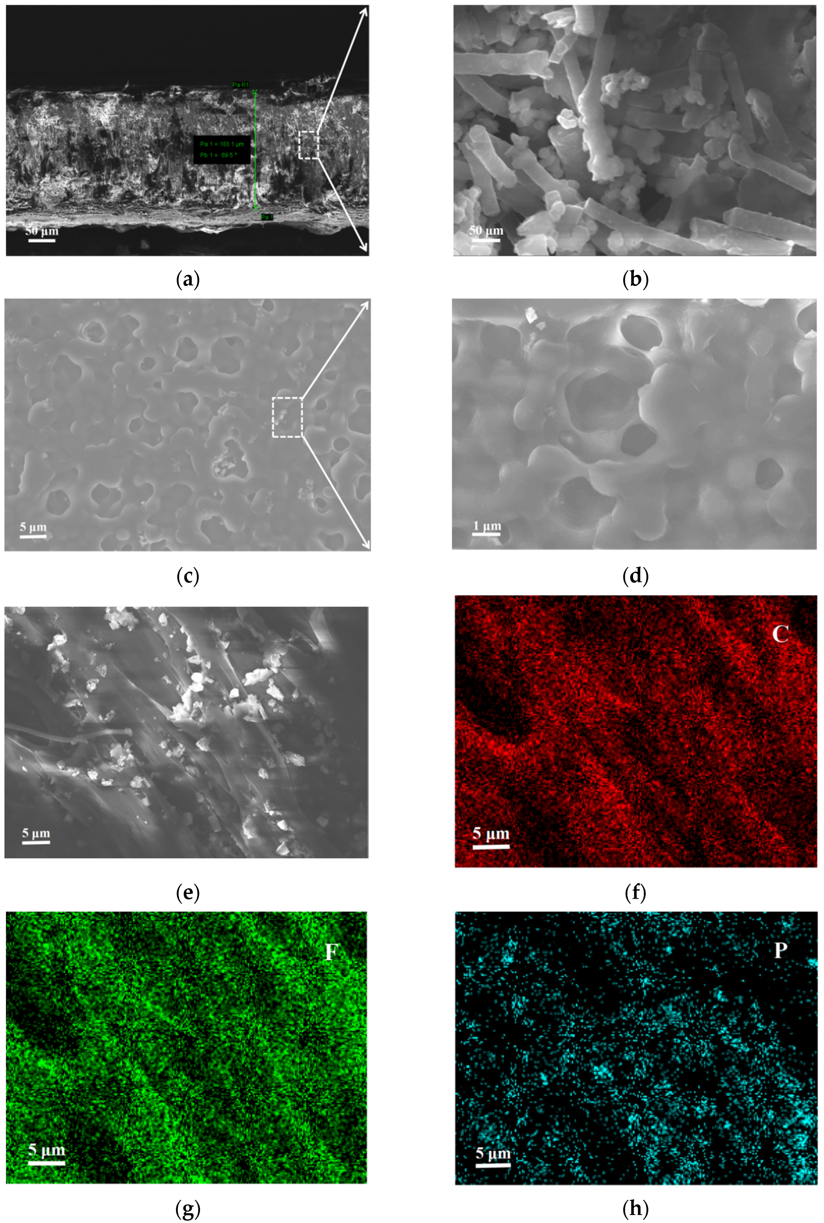
Figure 6 shows the CPEs interface and surface SEM characterization tests. Figure 6a,b shows the porous structure of CPEs, which is consistent with the SEM image of the surface in Figure 6c,d. The thickness of CPEs was 183.1 μm, and the porous structure formed by PVDF fiber winding nano-LATP particles was conducive to the transport of lithium-ions [38]. The EDS spectrum in Figure 6e–h shows the existence of element P, proving that LATP was uniformly distributed in CPEs, which itself was conducive to the formation of lithium-ion migration channels [39].
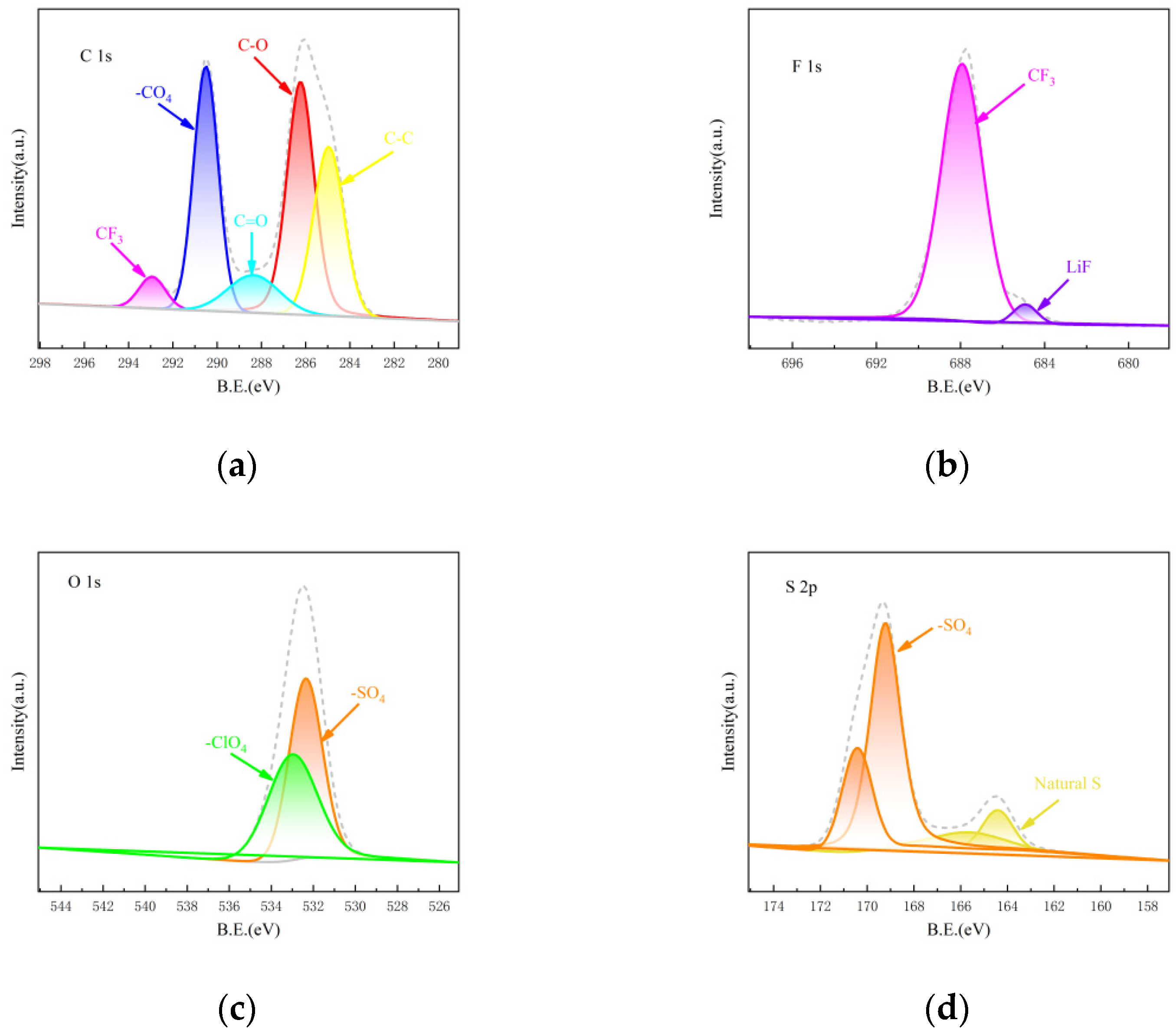
In order to further study the performance of CPEs, XPS tests were carried out on C, F, O and S elements in CPEs after 500 battery cycles. As shown in Figure 7a, the peak at 284.9 eV is the C-C bond peak of organic carbon, and the peak at 286.2, 288.3 and 290.5 eV are carbon–oxygen bonding peaks, indicating the existence of Li2CO3 in SEI film [40]. The characteristic peak of -CF3 appeared at 292.9 eV, corresponding to 684.9 eV in Figure 7b and indicating that -CF2 in PVDF underwent dehydrogenation to generate LiF [41], which exactly corresponded to the LiF peak at 687.9 eV in Figure 7b. The LiF can inhibit the growth of lithium dendrites and increase the diffusion rate of lithium-ions [42,43]. Figure 7c shows the O1s orbital graph. The characteristic peak of -ClO4 at 533 eV is the free -ClO4 in LiClO4. At 532.3 eV, -SO4 shows the positive S reaction to generate the sulfate salt, which is consistent with the -SO4 at 169.2 and 170.4 eV in Figure 7d. In Figure 7d, 164.4 and 165.6 eV are natural sulfur [44,45], and no peak bond of polysulfide is found, indicating that the PVDF/LiClO4/LATP electrolyte has a certain inhibitory effect on shuttle effect.
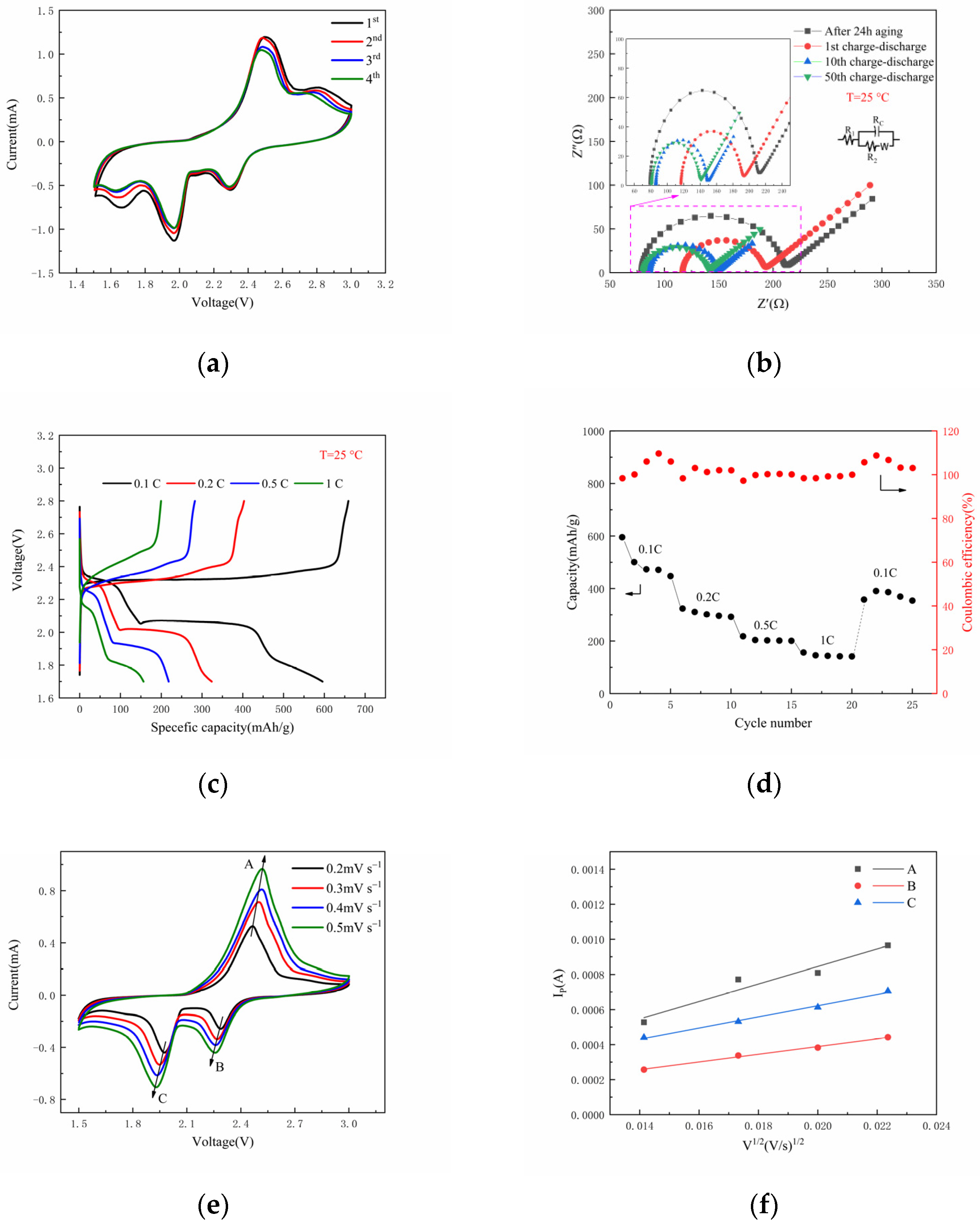
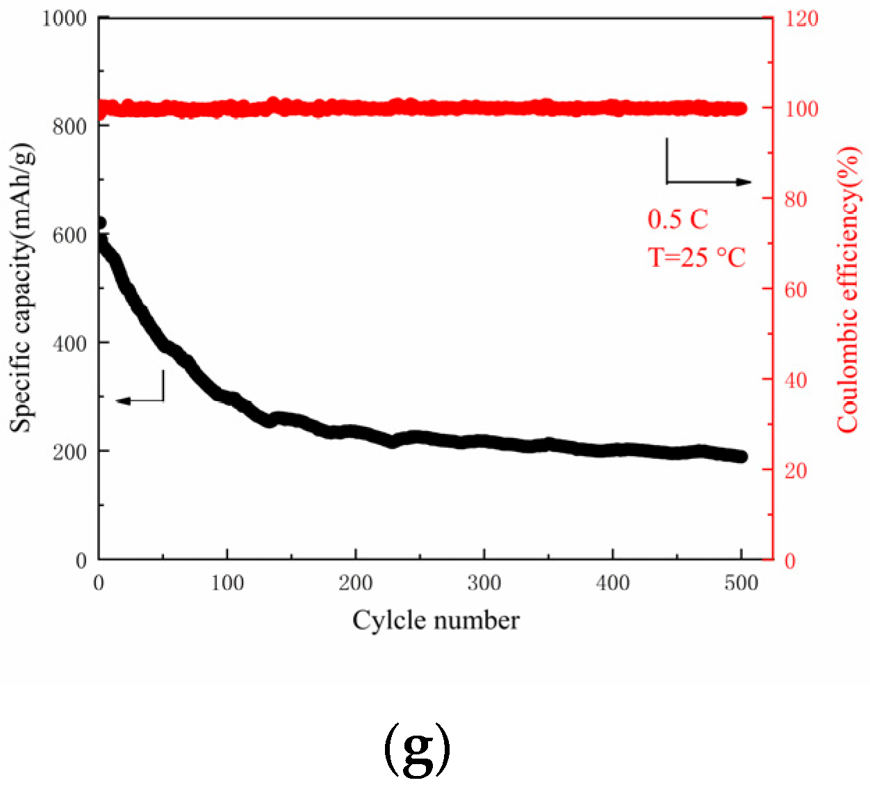
Figure 8a presents the CV curves of the Li|PVDF/LiClO4/LATP|NPCNF/S batteries in the voltage range of 1.5~3 V at a scanning rate of 0.2 mV S−1 at 25 °C. In the first scan, two reduction peaks appear at 2.3 V and 1.98 V, indicating that S8 is reduced to Li2Sn (4 ≤ n ≤ 8) and Li2S2/Li2S [46] during the discharge process. An oxidation peak that appeared at 2.5 V suggests Li2S2/Li2S oxidized in the process of charging. This is consistent with the phenomenon in the charge–discharge curve of Figure 8c. As the cycle continues, the SEI film tends to be stable and the test curves coincide well, which proves that the polymer electrolyte has good reversible properties. In order to further understand the electrochemical properties of solid-state lithium-sulfur batteries, the AC impedance after different charge–discharge cycles was measured, as shown in Figure 8b. All impedance spectra exhibit at least one semicircular with a Warburg component for the diffusion of lithium-ions through the electrode. After the first charge–discharge cycle, the RCT value was 193.5 Ω, as the number of cycles increased, Rct decreased and finally stabilized after the 10th cycle. It indicates that a stable SEI film is formed in the battery. Research regarding the rate performance test between 0.1 and 1 C is shown in Figure 8d. The discharge specific capacities of the Li|PVDF/LiClO4 LATP|NPCNF/S battery were 595.5 mAh g−1 (0.1 C, 1st), 292.3 mAh g−1 (0.2 C, 10st), 200.9 mAh g−1 (0.5 C, 15st), 141.5 mAh g−1 (1 C, 20st). When the rate was restored to 0.1 C, the specific capacity was 390.5 mAh g−1. This shows that the reversible specific capacity of the battery can be maintained after the charging and discharging cycle with a high rate, which proves that the battery has good rate performance. Moreover, the lithium ions diffusion coefficient can be obtained by a series of processing in terms of CV curves at different scan rates, shown in Figure 8e,f. The anodic and cathodic Li+ diffusion rate of D(ALi+) = 1.06 × 10⁻⁸, D(BLi+) = 2.06 × 10⁻⁹ and D(CLi+) = 4.36 × 10⁻⁹ cm2 s−1. Figure 8g shows the test of 500 long cycles of the battery at 25 °C and 0.5 C. The capacity decay of only 0.139% per cycle, and the coulomb efficiency of the whole cycle is close to 100%, indicating that the battery has good cycle performance. The conductive framework in NPCNF/S and composite electrolytes (CPEs) can provide embedded channels for polysulfide formed in the charge–discharge cycle and inhibit the deposition of polysulfide at the Li-anode interface, thus reducing the influence of “shuttle effect” and improving the performance of batteries.

4. Conclusions

In this paper, NPCNF as a high-efficiency conductive skeleton of sulfur electrode active material was prepared by template method. The PVDF/LiClO4/LATP electrolyte with good performance was prepared via mixed solution casting method. The NPCNF has a good morphology, such as with nano fiber, having an obvious adsorption effect on polysulfide, and the sulfur content can reach 62.9 wt%. The active material has a high carbonation degree of graphite and good electrical conductivity. At 25 °C, the ionic conductivity of PVDF/LiClO4/LATP electrolyte is 8.07 × 10⁻⁵ S cm−1, and the lithium-ion transfer rate can reach 0.77. With the addition of nanoscale LATP, the overall performance of CPEs is better than that of a garnet type and PVDF-based solid electrolytes. The assembled cell has a low impedance, and the RCT value of the first ring is 193.5 Ω. The battery has a good rate performance and can work at 1 C, maintaing a certain specific capacity. At 25 °C and 0.5 C, the specific discharge capacity of 500 cycles is 620.52 mAh g−1, and the capacity decay rate of each cycle is only 0.139%. This method for preparing the excellent sulfur positive electrode, combined with the composite electrolyte membrane, provides a new idea for improving the long cycle performance of solid-state lithium-sulfur batteries at room temperature.

Author Contributions

X.L.: Supervision, resources, conceptualization, writing—review and editing, project administration, and funding acquisition; Y.Z.: Investigation, methodology, writing—original draft, formal analysis, and data curation; Y.N.: data curation; D.H.: investigation; L.L.: funding acquisition; S.L.: writing—review and editing. All authors have read and agreed to the published version of the manuscript.

Funding

This research was supported by Guangxi Natural Science Foundation (No. 2020GXNSFAA297082), Guangxi Innovation Driven Development Project (No. AA18242036-2); the Fund Project of the Key Lab of Guangdong for ModernSurface Engineering Technology (No. 2018KFKT01); the National Natural Science Foundation of China (No. 52161033).

Data Availability Statement

The data that support the findings of this study are available upon reasonable request.

Acknowledgments

We are thankful to the following authors for their contributions, as well as for the purchase of materials and conducting the relative experiments: Yu Zhang, Xinghua Liang, Yujuan Ning, Dongxue Huang, Linxiao Lan and Siying Li.

Conflicts of Interest

The authors declare no conflict of interest.

References

  1. Pang, Q.; Liang, X.; Kwok, C.Y.; Nazar, L.F. Advances in lithium-sulfur batteries based on multifunctional cathodes and electrolytes. Nat. Energy 2016, 1, 16132. [Google Scholar] [CrossRef]
  2. Fu, A.; Wang, C.; Pei, F.; Cui, J.; Fang, X.; Zheng, N. Recent advances in hollow porous carbon materials for lithium-sulfur batteries. Small 2019, 15, 1804786. [Google Scholar] [CrossRef] [PubMed]
  3. Fan, L.L.; Deng, N.P.; Yan, J.; Li, Z.H.; Kang, W.M.; Cheng, B.W. The recent research status quo and the prospect of electrolytes for lithium sulfur batteries. Chem. Eng. J. 2019, 369, 874–897. [Google Scholar] [CrossRef]
  4. Liu, Y.J.; Zhou, P.; Hao, S. Rechargeable solid-state Li-Air and Li-S batteries: Materials, construction, and challenges. Adv. Energy Mater. 2018, 8, 1701602. [Google Scholar] [CrossRef]
  5. Urbonaite, S.; Poux, T.; Petr, N. Progress towards commercially viable Li-S battery cells. Adv. Energy Mater. 2015, 5, 1500118. [Google Scholar] [CrossRef]
  6. Skilton, R.A.; Bourne, R.A.; Amara, Z.; Horvath, R.; Jin, J.; Scully, M.J.; Streng, E.; Tang, S.L.Y.; Summers, P.A.; Wang, J. Remote-controlled experiments with cloud chemistry. Nat. Chem. 2014, 7, 1–5. [Google Scholar] [CrossRef] [Green Version]
  7. Tao, X.; Chen, X.; Xia, Y.; Huang, H.; Gan, Y.; Wu, R.; Chen, F.; Zhang, W. Highly mesoporous carbon foams synthesized by a facile, cost-effective and template-free Pechini method for advanced lithium-sulfur batteries. J. Mater. Chem. A 2013, 1, 3295–3301. [Google Scholar] [CrossRef]
  8. Zheng, G.; Yang, Y.; Cha, J.J.; Hong, S.S.; Cui, Y. Hollow carbon nanofiber-encapsulated sulfur cathodes for high specific capacity rechargeable lithium batteries. Nano Lett. 2011, 11, 4462–4467. [Google Scholar] [CrossRef]
  9. Manthiram, A.; Fu, Y.; Chung, S.H.; Zu, C.; Su, Y.S. Rechargeable lithium-sulfur batteries. Chem. Rev. 2014, 114, 11751–11787. [Google Scholar] [CrossRef]
  10. Mangani, L.R.; Villevieille, C. Mechanical vs. chemical stability of sulphide-based solid-state batteries. Which one is the biggest challenge to tackle? Overview of solid-state batteries and hybrid solid state batteries. J. Mater. Chem. A 2020, 8, 10150–10167. [Google Scholar] [CrossRef]
  11. Lei, D.; Shi, K.; Ye, H.; Wan, Z.; Wang, Y.; Shen, L.; Li, B.; Yang, Q.H.; Kang, F.; He, Y.B. Solid-state electrolytes: Progress and perspective of solid-state lithium-sulfur batteries. Adv. Funct. Mater. 2018, 28, 1870272. [Google Scholar] [CrossRef] [Green Version]
  12. Jeong, B.O.; Kwon, S.W.; Kim, T.J.; Lee, E.H.; Jeong, S.H.; Jung, Y. Effect of carbon black materials on the electrochemical properties of sulfur-based composite cathode for lithium-sulfur cells. J. Nanosci. Nanotechnol. 2013, 13, 7870–7874. [Google Scholar] [CrossRef]
  13. Li, X.; Sun, X.L. Nitrogen-doped carbons in Li-S batteries: Materials design and electrochemical mechanism. Front. Energy Res. 2014, 2, 49. [Google Scholar] [CrossRef] [Green Version]
  14. Yu, J.; Lee, M.; Kim, Y.; Lim, H.K.; Chae, J.; Hwang, G.S.; Lee, S. Agent molecule modulated low-temperature activation of solid-state lithium-ion transport for polymer electrolytes. J. Power Sources 2021, 505, 229917–229924. [Google Scholar] [CrossRef]
  15. Chen, X.; He, W.; Ding, L.X.; Wang, S.; Wang, H. Enhancing interfacial contact in all solid state batteries with a cathode-supported solid electrolyte membrane framework. Energy Environ. Sci. 2019, 12, 938–944. [Google Scholar] [CrossRef]
  16. Zheng, Y.; Yao, Y.; Ou, J.; Li, M.; Luo, D.; Dou, H.; Li, Z.; Amine, K.; Yu, A.; Chen, Z. A review of composite solid-state electrolytes for lithium batteries: Fundamentals, key materials and advanced structures. Chem. Soc. Rev. 2020, 49, 8790–8839. [Google Scholar] [CrossRef]
  17. Zuo, C.; Yang, M.; Wang, Z.; Jiang, K.; Li, S.; Luo, W.; He, D.; Liu, C.; Xie, X.; Xue, Z. Cyclophosphazene-based hybrid polymer electrolyte via epoxyamine reaction for high-performance all-solid-state lithium-ion batteries. J. Mater. Chem. A 2019, 7, 18871–18879. [Google Scholar] [CrossRef]
  18. Chen, Y.; Shi, Y.; Liang, Y.; Dong, H.; Hao, F.; Wang, A.; Zhu, Y.; Cui, X.; Yao, Y. Hyperbranched PEO-based hyperstar solid polymer electrolytes with simultaneous improvement of ion transport and mechanical strength. ACS Appl. Energy Mater. 2019, 2, 1608–1615. [Google Scholar] [CrossRef]
  19. Zhai, P.; Peng, N.; Sun, Z.; Wu, W.; Kou, W.; Cui, G.; Zhao, K.; Wang, J. Thin laminar composite solid electrolyte with high ionic conductivity and mechanical strength towards advanced all-solid-state lithium-sulfur battery. J. Mater. Chem. A 2020, 8, 23344–23353. [Google Scholar] [CrossRef]
  20. Barbosa, J.C.; Correia, D.M.; Gonçalves, R.; de Zea Bermudez, V.; Silva, M.M.; Lanceros-Mendez, S.; Costa, C.M. Enhanced ionic conductivity in poly(vinylidene fluoride) electrospun separator membranes blended with different ionic liquids for lithium ion batteries. J. Colloid Interface Sci. 2021, 582, 376–386. [Google Scholar] [CrossRef]
  21. Zhang, Y.; Zhao, Y.; Gosselink, D.; Chen, P. Synthesis of poly(ethylene-oxide)/nanoclay solid polymer electrolyte for all solid-state lithium/sulfur battery. Ionics 2015, 21, 381–385. [Google Scholar] [CrossRef]
  22. McGrogan, F.P.; Swamy, T.; Bishop, S.R.; Eggleton, E.; Porz, L.; Chen, X.; Chiang, Y.M.; Van Vliet, K.J. Compliant yet brittle mechanical behavior of Li2S-P2S5 lithium-ion-conducting solid electrolyte. Adv. Energy Mater. 2017, 7, 1602011. [Google Scholar] [CrossRef] [Green Version]
  23. Li, M.; Bai, Z.; Li, Y.; Ma, L.; Dai, A.; Wang, X.; Luo, D.; Wu, T.; Liu, P.; Yang, L.; et al. Electrochemically primed functional redox mediator generator from the decomposition of solid state electrolyte. Nat. Commun. 2019, 10, 1890–1898. [Google Scholar] [CrossRef]
  24. Li, M.; Frerichs, J.E.; Kolek, M.; Sun, W.; Zhou, D.; Huang, C.J.; Hwang, B.J.; Hansen, M.R.; Winter, M.; Bieker, P. Solid-state lithium-sulfur battery enabled by Thio-LiSICON/Polymer composite electrolyte and sulfurized polyacrylonitrile cathode. Adv. Funct. Mater. 2020, 30, 1910123. [Google Scholar] [CrossRef] [Green Version]
  25. Deng, S.; Sun, Q.; Li, M.; Adair, K.; Yu, C.; Li, J.; Li, W.; Fu, J.; Li, X.; Li, R.; et al. Insight into cathode surface to boost the performance of solid-state batteries. Energy Storage Mater. 2021, 35, 661–668. [Google Scholar] [CrossRef]
  26. Schell, K.G.; Bucharsky, E.C.; Lemke, F.; Hoffmann, M.J. Effect of calcination conditions on lithium conductivity in Li1.3Ti1.7Al0.3(PO4)3 prepared by sol-gel route. Ionics 2016, 23, 821–827. [Google Scholar] [CrossRef]
  27. Han, J.P.; Zhang, B.; Wang, L.Y.; Zhu, H.L.; Qi, Y.X.; Yin, L.; Li, N.; Lun, N.; Bai, Y.J. Li1.3Al0.3Ti1.7(PO4)3 behaving as a fast ionic conductor and bridge to boost the electrochemical performance of Li4Ti5O12. ACS Sustain. Chem. Eng. 2018, 6, 7273–7282. [Google Scholar] [CrossRef]
  28. Zheng, F.; Kotobuki, M.; Song, S.; Lai, M.O.; Lu, L. Review on solid electrolytes for all-solid-state lithium-ion batteries. J. Power Sources 2018, 389, 198–213. [Google Scholar] [CrossRef]
  29. Gao, H.; Xue, L.; Xin, S.; Goodenough, J.B. A high-energy-density potassium battery with a polymer-gel electrolyte and a polyaniline cathode. Angew. Chem. Int. Ed. Engl. 2018, 130, 5449–5453. [Google Scholar] [CrossRef]
  30. Fu, C.; Ma, Y.; Zuo, P.; Zhao, W.; Gao, Y.; Tang, W.; Yin, G.; Wang, J. In-situ thermal polymerization boosts succinonitrile-based composite solid-state electrolyte for high performance Li-metal battery. J. Power Sources 2021, 496, 229861. [Google Scholar] [CrossRef]
  31. Cheng, D.; Zhao, Y.; An, T.; Wang, X.; Zhou, H.; Fan, T. 3d interconnected crumpled porous carbon sheets modified with high-level nitrogen doping for high performance lithium sulfur battery. Carbon 2019, 154, 58–66. [Google Scholar] [CrossRef]
  32. Xu, Z.L.; Kim, J.K.; Kang, K. Carbon nanomaterials for advanced lithium sulfur batteries. Nano Today 2018, 19, 84–107. [Google Scholar] [CrossRef]
  33. Cai, X.; Lei, T.; Sun, D.; Lin, L. A critical analysis of the α, β and γ phases in poly(vinylidene fluoride) using ftir. Rsc Adv. 2017, 7, 15382–15389. [Google Scholar] [CrossRef] [Green Version]
  34. Shan, Y.; Li, L.; Yang, X. Solid-state polymer electrolyte solves the transfer of lithium ions between the solid–solid interface of the electrode and the electrolyte in lithium–sulfur and lithium-ion batteries. ACS Appl. Energy Mater. 2021, 4, 5101–5112. [Google Scholar] [CrossRef]
  35. Baskaran, R.; Selvasekarapandian, S.; Kuwata, N.; Kawamura, J.; Hattori, T. Conductivity and thermal studies of blend polymer electrolytes based on PVAc–PMMA. Solid State Ion. 2006, 177, 2679–2682. [Google Scholar] [CrossRef]
  36. Cho, Y.G.; Hwang, C.; Cheong, D.S.; Kim, Y.S.; Song, H.K. Gel/solid polymer electrolytes characterized by in situ gelation or polymerization for electrochemical energy systems. Adv. Mater. 2019, 31, 1804909. [Google Scholar] [CrossRef]
  37. Kim, D.H.; Hwang, S.; Cho, J.J.; Yu, S.; Kim, S.; Jeon, J.; Ahn, K.H.; Lee, C.; Song, H.K.; Lee, H. Toward fast operation of lithium batteries: Ion activity as the factor to determine the concentration polarization. ACS Energy Lett. 2019, 4, 1265–1270. [Google Scholar] [CrossRef]
  38. Bag, S.; Zhou, C.; Kim, P.J.; Pol, V.G.; Thangadurai, V. Lif modified stable flexible PVDF-garnet hybrid electrolyte for high performance all-solid-state li-s batteries. Energy Storage Mater. 2019, 24, S2405–S8297. [Google Scholar] [CrossRef]
  39. Zhang, Q.; Wang, Q.; Huang, S.; Jiang, Y.; Chen, Z. Preparation and electrochemical study of PVDF-HFP/LATP/g-C3N4 composite polymer electrolyte membrane. Inorg. Chem. Commun. 2021, 131, 108793–108799. [Google Scholar] [CrossRef]
  40. Yue, Q.; Shi, S.; Hong, L.; Jr, L. Defect thermodynamics and diffusion mechanisms in Li2CO3 and implications for the solid electrolyte interphase in Li-ion batteries. J. Phys. Chem. B 2013, 117, 8579–8593. [Google Scholar]
  41. Bai, Y.; Li, L.; Li, Y.; Chen, G.; Zhao, H.; Wang, Z.; Li, H.; Wu, F.; Wu, C. Reversible and irreversible heat generation of nca/si–c pouch cell during electrochemical energy-storage process. Energy Storage Mater. 2019, 16, 411–418. [Google Scholar] [CrossRef] [Green Version]
  42. Yuan, Y.; Feng, W.; Ying, B.; Li, Y.; Chen, G.; Wang, Z.; Wu, C. Regulating li deposition by constructing lif-rich host for dendrite-free lithium metal anode. Energy Storage Mater. 2018, 16, 411–418. [Google Scholar] [CrossRef]
  43. Chao, X.; Bing, S.; Gustafsson, T.; Edstrm, K.; Hahlin, M. Interface layer formation in solid polymer electrolyte lithium batteries: An xps study. J. Mater. Chem. A 2014, 2, 7256–7264. [Google Scholar]
  44. Fang, R.; Xu, H.; Xu, B.; Li, X.; Li, Y.; Goodenough, J.B. Reaction mechanism optimization of solid-state Li-S batteries with a PEO-based electrolyte. Adv. Funct. Mater. 2020, 31, 2001812. [Google Scholar] [CrossRef]
  45. Liang, X.; Hart, C.; Pang, Q.; Garsuch, A.; Weiss, T.; Nazar, L.F. A highly efficient polysulfide mediator for lithium−sulfur batteries. Nat. Commun. 2015, 6, 5682–5689. [Google Scholar] [CrossRef] [Green Version]
  46. Zhang, X.; Chen, K.; Sun, Z.; Hu, G.; Xiao, R.; Cheng, H.M.; Li, F. Structure-related electrochemical performance of organosulfur compounds for lithium-sulfur batteries. Energy Environ. Sci. 2020, 13, 1076–1095. [Google Scholar] [CrossRef]
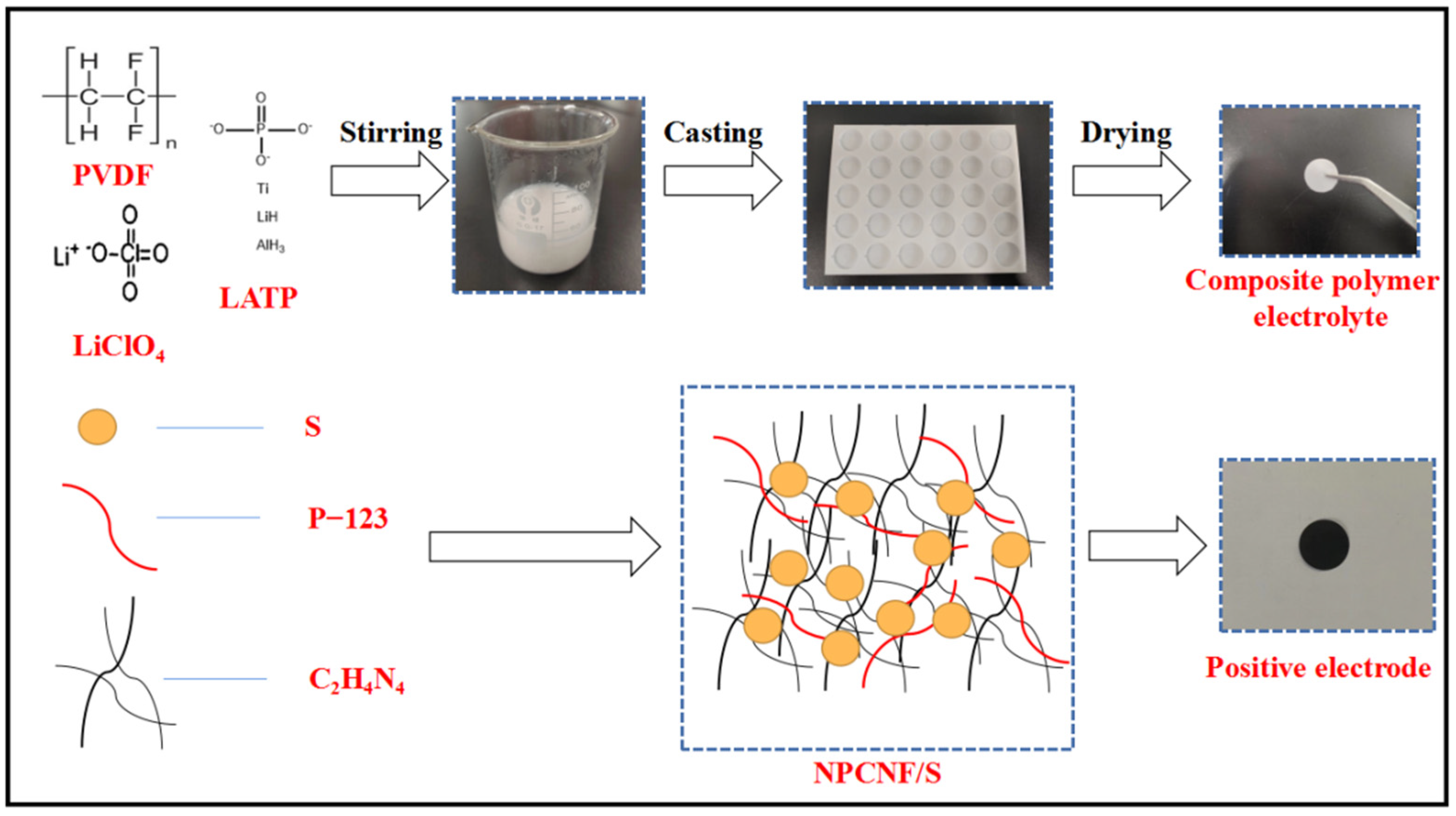
Figure 1. A schematic illustration of the fabrication of the positive electrolyte and CPEs.
Nanomaterials 12 02614 g001
Figure 2. (a) XRD tests of the NPCNF and NPCNF/S (b) Raman spectra of NPCNF and NPCNF/S (c) TGA curves of S, NPCNF and NPCNF/S (d) The photograph of the static adsorption test.
Nanomaterials 12 02614 g002
Figure 3. (a,b) SEM images of NPCNF (c,d) SEM images of NPCNF/S (e) SEM image of NPCNF/S and corresponding elemental mapping images (f) C element (g) N element (h) S element.
Nanomaterials 12 02614 g003
Figure 4. (a) XRD tests of the CPEs (b) ATR-FTIR (c) TGA curves of CPEs (d) DTG curves of CPEs.
Nanomaterials 12 02614 g004
Figure 5. (a) EIS of CEPs; (b) Arrhenius plots of CEPs; (c) electrochemical window test; (d) time-ampere measurement symmetrical Li/CEPs/Li battery at 0.5 mV polarization and Nyquist plot initial/steady state internal illustration; (e) a photograph showing the flexibility of CEPs.
Nanomaterials 12 02614 g005
Figure 6. (a,b) A cross-sectional SEM image of CEPs; (c,d) SEM images of CEPs; (e) an SEM image of CEPs and corresponding elemental mapping images; (f) C element; (g) F element; (h) P element.
Nanomaterials 12 02614 g006
Figure 7. XPS of the CEPs after 500 cycles (a) C 1s (b) F 1s (c) O 1s (d) S 2p.
Nanomaterials 12 02614 g007
Figure 8. (a) CV curves of the Li|PVDF/LiClO4/LATP|NPCNF/S cell at a scan rate of 0.2 mV s−1; (b) EIS of the Li|PVDF/LiClO4/LATP|NPCNF/S cell at different cycle numbers; (c) voltage-specific capacity curve of the Li|PVDF/LiClO4/LATP|NPCNF/S cell; (d) rate performance; (e) CV curves of the cell in the range of 0.2–0.5 mV s−1; (f) corresponding linear fits of the peak currents of the cell; (g) cyclic performance of the Li|PVDF/LiClO4/LATP|NPCNF/S cell at 0.5 C.
Nanomaterials 12 02614 g008aNanomaterials 12 02614 g008b
Publisher’s Note: MDPI stays neutral with regard to jurisdictional claims in published maps and institutional affiliations.