Abstract
CuInP2S6 (CIPS) is a novel two-dimensional (2D) van der Waals (vdW) ferroelectric layered material with a Curie temperature of TC~315 K, making it promising for great potential applications in electronic and photoelectric devices. Herein, the ferroelectric and electric properties of CIPS at different thicknesses are carefully evaluated by scanning probe microscopy techniques. Some defects in some local regions due to Cu deficiency lead to a CuInP2S6–In4/3P2S6 (CIPS–IPS) paraelectric phase coexisting with the CIPS ferroelectric phase. An electrochemical strain microscopy (ESM) study reveals that the relaxation times corresponding to the Cu ions and the IPS ionospheres are not the same, with a significant difference in their response to DC voltage, related to the rectification effect of the ferroelectric tunnel junction (FTJ). The electric properties of the FTJ indicate Cu+ ion migration and propose that the current flow and device performance are dynamically controlled by an interfacial Schottky barrier. The addition of the ferroelectricity of CIPS opens up applications in memories and sensors, actuators, and even spin-orbit devices based on 2D vdW heterostructures.
1. Introduction
Two-dimensional (2D) ferroelectric materials are gaining extensive attention. It can effectively improve device performance when applied to devices such as memory, capacitors, actuators, and sensors [1,2,3,4]. Nowadays, people regard such kinds of 2D materials as var der Waals (vdW) layered ferroelectric materials, which benefit from covalently bonded polar or non-polar monolayers by Van der Waals forces and exhibit ferroelectric properties. However, reports of ferroelectric 2D materials at room temperature are rare. Because of the depolarization field with decreasing thickness, there is an enormous challenge in maintaining ferroelectricity in ultrathin ferroelectric films. Ferroelectricity is remained elusive in the 2D material library [5,6] Van der Waals (vdW) layered ferroelectric materials has become a promising research branch in condensed matter physics [7,8], among which copper indium thiophosphate, CuInP2S6 (CIPS), is one of the most representative materials because of its room temperature ferroelectricity [9]. CIPS is promised to play an important role in nonvolatile memory. A recent experiment reported that the vdW ferroelectric tunnel junction (FTJ) device based on CIPS achieved a high tunneling electroresistance (TER) ratio [10,11]. Quantum transport device simulations of an FTJ based on CIPS and graphene demonstrate that scaling of the ferroelectric layer thickness exponentially not only significantly builds up the ferroelectric tunneling ON current but also reduces the read latency, in addition to enabling the FTJs with CIPS bilayers or trilayers to read speed in nanoseconds [12]. There are also outstanding endurance and retention characteristics for FTJ devices [3].
It was reported that giant intrinsic negative longitudinal piezoelectricity was observed in 2D layered CIPS. Lu You et al. [12] tested the converse piezoelectric effects of poly(vinylidene difluoride (PVDF), CIPS, and lead zirconate titanate (PZT) using a piezoelectric microscope and concluded that the electromechanical properties of CIPS are the same as those of PVDF with a negative longitudinal piezoelectric effect but opposite to those of PZT. This abnormal electromechanical phenomenon is caused by the significant deformation sensitivity of the weak interlayer interaction and is mediated by the high displacive instability of Cu ions. Several groups have discussed the origins of negative piezoelectricity. Yubo Qi and Andrew M. Pappe [13] attributed the negative piezoelectricity to the “lag of Wannier center” effect by proposing a negative clamped-ion term in the low-dimensional layered materials. John A. Brehm et al. [14] combined first-principles calculations with local electromechanical material characterization. They predicted and verified the existence of a uniaxial quadruple potential well for Cu displacements achieved by the van der Waals gap in CIPS. This led to the explanation that the negative longitudinal piezoelectric coefficient stems from the low polarization and very high sensitivity to a strain of the Cu atoms within the layer. Due to the negative piezoelectricity, CIPS has more complex piezoelectric properties, which gives it potential application prospects for 2D vdW materials with the same complex piezoelectric behavior in calculation and energy conversion. Therefore, it is crucial to study the piezoelectric behavior of CIPS.
Recently, to achieve resistance changes by ferroelectric switching, a ferroelectric field-effect transistor (FeFET) has been proposed, which uses ferroelectric materials instead of the oxide layer in a FET [15,16,17]. The causesFeFET exhibits two resistive states due to the hysteresis of ferroelectric switching. Furthermore, ferroelectric tunneling junctions and ferroelectric diodes were also investigated. It is reported that the polarization-modulation of Schottky-like barriers realizes the resistive change [18,19]. Yet, the vast majority of these devices use conventional ferroelectric materials such as PbTiO3 and BaTiO3 [20]. Affected by the three-dimensional nature of the ferroelectric oxide lattices, it is necessary for epitaxially grown high-quality films to select the substrates with a small lattice mismatch [21]. This seriously limits the possible application of materials in ferroelectric heterostructure devices. Therefore, it may be fundamentally and practically beneficial to study weakly bonded non-oxide ferroelectric compounds. Beyond that, the pioneering work on graphene has attracted an intense search for other 2D materials [22,23].
In this work, the crystal structure and ferroelectricity in crystalline CIPS nanoflakes are investigated at room temperature. Thin layer crystals in their pristine state show ferroelectric domains that are visualized directly. Piezoresponse force microscopy (PFM) measurements show that the polarization is stable and switchable in different layers of CIPS, and a negative piezoelectric effect is observed. Furthermore, we observed the ion migration phenomenon in CIPS via electrochemical strain microscopy (ESM). Finally, to obtain insight into the nature of the TER phenomena in the CIPS—based FTJs, we investigated their current—voltage (I–V) characteristics with a conductive probe microscope.
2. Experimental Section
2.1. Sample Preparation and Structural Characterization
All CIPS crystals were purchased from 6Carbon Technology (Shenzhen, China). The purchased synthetic bulk crystals were mechanically exfoliated onto platinized silicon substrates to obtain the flakes. The flake thickness was measured with a three-dimensional (3D) laser confocal microscope (VK-X1100, KEYENCE CORPORATION., Itasca, IL, USA) and an atomic force microscope (AFM, Cypher S, OXFORD INSTRUMENTS, Abingdon, Oxfordshire, UK). The microscope objective lenses used in our experiments are ×5, ×10, ×20, ×50, ×100, and the microscopic ocular is ×5. The numerical aperture and working distance of the microscope objective lens with ×100 magnification are 0.3 mm and 4.7 mm, respectively. The confocal Raman system (LabRAM HR, HORIBA Instuments(SHANGHAI) co. LTD, Shanghai, China) with 532 nm laser excitation was used to collect Raman spectra. The morphologies and structures of the as—prepared samples were collected by transmission electron microscopy (TEM, JEM-3200FS, JEOL (BEIJING) Co., Ltd. GUANGZHOU BRANCH, Beijing, China).
2.2. Piezoelectric Force Microscopy (PFM) Measurements
The PFM measurements were performed on μm—sized CIPS flakes on the crystal surface. The silver paste was used to attach the sample to the sample stage, which served as an electric back contact. PFM image scanning measurements were performed using a piezoelectric force microscope (PFM) with Au- and diamond-coated Si cantilever tips (FM-LC, 100 kHz and 8 N/m), respectively. The cantilever tip acted as a local variable electrode. The electric voltage was applied to the sample surface via the conductive PFM tip. The sample was cleaved using Scotch tape directly before the measurements. The topography of CIPS flakes was probed in AC mode, while the piezoelectric and ferroelectric responses were measured using dual AC resonance tracking PFM (DART-PFM) mode. The local piezoresponse hysteresis loops were measured 10 times at each position at multiple different arbitrary points.
2.3. Electrochemical Strain Microscopy (ESM) Measurements
Relaxation and variable ESM measurements were performed using an atomic force microscope. Conductive Au- and diamond-coated Si cantilever tips (FM-LC, 100 kHz, and 8 N/m) were used in all measurements.
2.4. Conductive Atomic Force Microscopy (C-AFM) Measurements
Local current-voltage and current phase diagram measurements were performed by C-AFM using with Au- and diamond-coated Si cantilever tips (FM-LC, 100 kHz, and 8 N/m). I–V curves were collected perpendicular to the CIPS samples in C-AFM mode.
3. Results and Discussion
3.1. Structural Characterization
The room-temperature crystal structure of CIPS was first discovered in 1995 using single-crystal X-ray diffraction [24]. Bulk CIPS is composed of vertically stacked, weakly interacting layers bound together by vdW interactions. The metal cations and P–P pairs fill the octahedral voids in the sulfur framework in a CIPS crystal (Figure 1a). A complete unit cell is reported to consist of two adjacent monolayers due to the site exchange between Cu and the P–P pairs from one layer to another [25]. Figure 1b shows two typical Raman spectra measured in different regions of a CIPS flake on a Pt/Si substrate. In general, we observed five Raman active modes, including δ(S–P–P) modes at 162.9 cm−1, δ(S–P–S) modes around 226.1 cm−1, and 263.3 cm−1, an active mode from the cations at 303.2 cm−1, andυ(P–P) and υ(P–S) modes at 374.3 cm−1 and 436.4 cm−1, respectively. The tested Raman results are consistent with the former reports on CIPS crystals [26,27]. P–S bond stretching vibrations (υ) can be resolved to A1g + A2u + Eu + Eg. The S–P–S modes change the S–P–S angles, resulting in another set of A1g + A2u + Eu + Eg. The P–P bond is associated with bending the PS3 groups, which accounts for Eu + Eg. Twisting (P2S6)4− oscillation is related to the A1u mode [27]. The Raman spectra in orange showed a strong peak at ~303 cm−1, which corresponds to the cations [26]. The blue curve showed a weak and broad peak at ~303 cm−1, which is mainly related to the reduction of Cu content. It is believed to originate from the paraelectric phase of CIPS–IPS, where IPS stands for In4/3P2S6, appearing in the flake due to Cu+ deficiency [26,27]. The transmission electron microscope (TEM) images show two structures on the same CIPS flakes (Figure 1c), which correspond to the monoclinic and triclinic phases, consistent with the Raman spectrum.
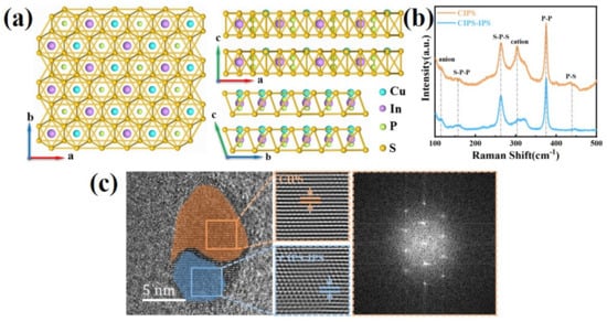
Figure 1.
Material characterization of CIPS flake. (a) Top and side views of the CIPS crystal structure. In the atomic model, the yellow networks are S triangular networks, and the green, purple, and blue balls are P, In, and Cu atoms, respectively. (b) Raman spectra of CIPS flakes, including ferroelectric and paraelectric phases on the Pt substrate with 532 nm laser excitation. (c) The TEM characterizations of CIPS crystal include fast Fourier transform (FFT, right) and filtered inverse FFT (middle) patterns of the selected areas, respectively.
3.2. Ferroelectric Domain and Domain Switching
To approve the ferroelectricity of CIPS flakes with different thicknesses, the domain distribution of the CIPS flakes was investigated in 3 nm, 9 nm, 12 nm, 21 nm, 35 nm, and 78 nm CIPS flakes by piezoresponse force microscopy (PFM). The domain evolution of the CIPS flakes was observed with height, amplitude, and phase images, as shown in Figure 2a–f. The domain size varied with the increasing thickness of the CIPS. As shown in Figure 2a–f, the size of the ferroelectric domains increases with the thickness of the CIPS flakes. Domains vary in size but are on the order of ~100 nm and ~1 μm in diameter, respectively, different from reports in the literature [7]. In our experience, it is easy to observe clear domain structures in CIPS flakes with thicknesses in the thickness range from 20 to 40 nm, as shown in Figure 2d,e. We observed the reversed piezoelectric effect in the typical amplitude-voltage “butterfly” loops by scanning the piezoresponse hysteresis loops in dual AC resonance tracking PFM (DART-PFM) mode. There are regions where the ferroelectric inversion loop disappears in the 20 nm CIPS flakes, which may be related to the paraelectric phase caused by Cu2+ segregation.
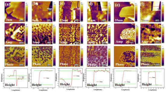
Figure 2.
PFM images including height, amplitude, and phase image (upper three), and height curves (bottom row) of CIPS flakes with different thicknesses. (a) 3 nm, (b) 9 nm, (c) 12 nm, (d) 21 nm, (e) 35 nm, and (f) 78 nm.
According to the above results, we chose the CIPS sample with a thickness of 20 nm to investigate the ferroelectric switching behavior. Well-defined butterfly loops of the saturated PFM amplitude and the distinct 180° switching of the phase signals were observed, as shown in Figure 3a,b, indicating switchable ferroelectric polarization in the CIPS flakes with different thicknesses (28 nm and 20 nm). We divided the hysteresis loops into four sections, as shown in Figure 3a–c, and observed that the direction of the polarization switching of CIPS was consistent with that of PVDF [28], showing negative piezoelectricity, which arose from the low polarization of Cu atoms in the CIPS layer [14]. We still observed abnormal butterflies and switching of the phase loops in the 25 nm and 20 nm CIPS, however, as shown in Figure 3c,d. There are the following several possible reasons for the abnormal switching loops: One, when sweeping the electric fields in the reverse sequence, the piezoelectric response curves show asymmetric shapes. This phenomenon was attributed to the existence of remnant-injected electrons. Due to the different diffusion distances in both the positive and negative electric range, the injected electrons cannot be eliminated absolutely when applying a lower electric field [29]. Two, the abnormal hysteresis loops may also relate to negative electrostriction and electrostatic signal contributions accompanied by charge injection during scanning [30]. Three, abnormal domain switching is generated due to in-plane ionic migration in CIPS [31]. Since the Cu is deficient, when applying an electric field, a few regions of the CIPS undergo a chemical phase separation into a paraelectric In4/3P2S6 phase and a ferroelectric CuInP2S6 phase [32]. Abnormal hysteresis loops may be from the local paraelectric phase of the CuInP2S6–In4/3P2S6 region due to Cu deficiency [27].
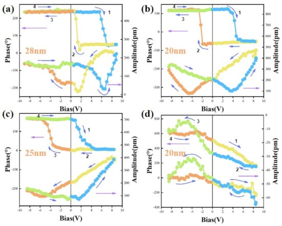
Figure 3.
Ferroelectric polarization switching by PFM for CIPS flakes with different thicknesses. The PFM amplitude (green) and phase (blue) hysteresis loops during the switching process for CIPS flakes with thickness of (a) 28 nm, (b) 20 nm, (c) 25 nm, and (d) another area of the sample with the thickness of 20 nm.
To investigate the in-plane ionic migration, we carried out a relaxation test to analyze the local ionic dynamics of CIPS via electrochemical strain measurements (ESM), as shown in Figure 4 [33,34]. As schematically shown in Figure 4a, a direct-current (DC) voltage is applied on top of an AC voltage to induce a longer-range redistribution of ions in CIPS flakes during the probe. After removing the DC voltage, the ions relax back to their original equilibrium state. The local dynamics can be deduced from the time constant associated with the relaxation of ESM amplitude, as shown in Figure 4b. The DC voltage is applied on top of the AC following the profile shown in Figure 4a to induce a longer-range redistribution of Cu+ ions; meanwhile, polarizing the sample over a larger scale. The faster relaxation shown in Figure 4d corresponds to the Vegard strain directly related to the ionic concentration of Cu+. While slower relaxation in Figure 4d is because of the induced electrochemical dipoles and results from the readjustment of the negative InP2S6− in response to the redistributed Cu+. The process takes longer over a much shorter distance. This phenomenon verifies our conjecture that the IPS paraelectric phase forms in the Cu-absent region due to the Cu ion migration, with no ferroelectric polarization switching. That is, the relaxation of Cu ions is associated with the change in ferroelectric polarization after the addition of voltage, and the longer time is related to the saturation phenomenon of polarization specific to CIPS reported in the literature.
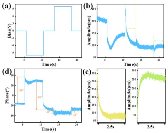
Figure 4.
Relaxation dynamics in local electrochemical strain measurements of CIPS. (a) Illustrated DC profile applying in the relaxation measurements. (b,d) ESM amplitude-time and phase-time curves were obtained corresponding to the DC profile. (c) Zoomed—in relaxation curves of (b) were recorded after removing negative and positive DC voltage, respectively.
3.3. Electric Properties of Pt/CuInP2S6/Au FTJ
CIPS by itself is the only two-dimensional ferroelectric material with a ferroelectric transition temperature (Tc) just over room temperature. Based on the above studies, we have observed the paraelectric phase in CIPS flakes, but it is rarely reported whether the paraelectric phase affects the device’s performance. In this work, we used conductive AFM to study the electric properties of a CIPS FTJ as shown in Figure 5. The electrical characterization of an Au/CIPS/Pt vdW FTJ is shown in Figure 5a for a device with a 2-nm-thick CIPS layer. Figure 5b,c shows the topography and current images of the CIPS flakes. The leakage current scanning was performed within a 3 × 3 μm2 area at a read voltage of 10 mV. The observed local conductive path regions indicated good electrical conductivity in the CIPS flakes.
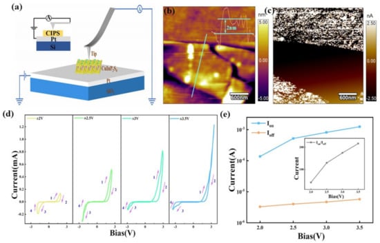
Figure 5.
Electrical characterization of a Si/Pt/CIPS/Au diode with1.7 nm CIPS. (a) Schematic representation of the experimental setup for C-AFM measurements. (b) Topography image of the CIPS nano flake with a thickness of 2 nm on the Si/SiO2/Ti/Pt substrate. The inset shows the height map of the CIPS flake. (c) The corresponding current phase diagram of CIPS flakes. (d) I–V curves measured with increasing sweep voltages, where VMax is from 2 to 3.5 V. (e) Ion and Ioff are the on and off current of the FTJ with resistance switching behavior, which are also corresponding to the low and high resistance states, read from (d) under different scanning voltages, with the inset the calculated switching ratio based on (d).
Figure 5d presents the I–V curves of a CIPS FTJ, measured with varying sweep ranges (Vmax from 2 V to 3.5 V). We can observe resistive switching in both positive and negative voltage ranges, demonstrating that FTJ has superior continuous current modulation and self-rectification functions. The I–V curves show a nonsymmetrical contour, and worse symmetry appears with increased voltage. This corresponds to the Cu2+ migration process. Before the Cu2+ migration, a Schottky barrier must be overcome. Due to the difference in the work functions between Au and Pt, the current of the I–V curve under a positive voltage and a negative voltage is asymmetric. The current limiting behavior in the negative range is similar to the rectifying effect of diodes. As the applied voltage increases, the I–V curves show more obvious hysteresis in the positive range, which is always regarded as a resistance switching behavior. As shown in Figure 5e, the Ion and Ioff correspond to the on-current and off-current when applying different voltages during the resistance switching. As shown in the inset of Figure 5e, the Ion/Ioff of the FTJ with an ultra-thin CIPS film is over 200, which is comparable with the previous results [10], indicating that CIPS has good development prospects in the research on and application of nonvolatile memory devices.
4. Conclusions
In summary, we clearly observed the domain structure of CIPS with a thickness of 20–40 nm in PFM measurements and found that the hysteresis loop of CIPS showed the same negative longitudinal piezoelectric effect as PVDF, indicating the complexity of the piezoelectric response of CIPS. We used electrochemical strain microscopy (ESM) to further study Cu2+ segregation and discovered different relaxation times between the Cu2+ and an InP2S62− ion groups, with both ions showing significant differences in their DC voltage response. These observations imply that in the regions where the ferroelectric inversion loop cannot be observed, Cu2+ segregation occurs, and InP2S62− paraelectric phase is formed. In addition, the Cu2+ relaxation is related to the change in the ferroelectric polarization after the application of voltage, and the longer relaxation time is relevant to the distinctive ferroelectric polarization saturation in CIPS2. Finally, we constructed a Pt/CIPS/Au FTJ. We observed resistance switches in the positive and negative voltage ranges, demonstrating that FTJ has superior continuous current modulation and self-rectification functions. Combined with its piezoelectric characteristics, layered ferroelectric CIPS is suitable not only for memory, but also for sensors, actuators, and even spin-orbit devices based on vdW heterostructures.
Author Contributions
Conceptualization, T.J., Q.G. and Z.C.; methodology, T.J., Y.C. (Yanrong Chen); validation, Y.C. (Yali Cai), W.D., C.Z., L.Y. and W.Y.; writing—original draft preparation, T.J. and Y.C. (Yanrong Chen); writing—review and editing, T.J., Y.Y., Q.G. and Z.C.; visualization, H.K.; formal analysis, Z.C.; investigation, H.K.; resources, T.J. and S.Y.; supervision, S.Y., T.J. and Y.C. (Yanrong Chen) contribute equally. All authors have read and agreed to the published version of the manuscript.
Funding
This research was funded by the National Natural Science Foundation of China (51702351, 51777209), the Basic and Applied Basic Research Foundation of Guangdong Province (2020B1515120019), Guangdong Provincial Key Laboratory (2014B030301014), and the Shenzhen Science and Technology Innovation Committee (JCYJ20170413152832151, KQTD20170810160424889). And The APC was funded by JCYJ20170413152832151.
Institutional Review Board Statement
Not applicable.
Informed Consent Statement
Not applicable.
Data Availability Statement
Not applicable.
Conflicts of Interest
The authors declare no conflict of interest.
References
- Zhou, S.; You, L.; Zhou, H.; Pu, Y.; Gui, Z.; Wang, J. Van der Waals layered ferroelectric CuInP2S6: Physical properties and device applications. Front. Phys. 2021, 16, 13301. [Google Scholar] [CrossRef]
- Zhao, Z.; Rakheja, S.; Zhu, W. Nonvolatile Reconfigurable 2D Schottky Barrier Transistors. Nano Lett. 2021, 21, 9318–9324. [Google Scholar] [CrossRef] [PubMed]
- Yang, N.; Chen, H.-Y.; Wu, J.; Wu, T.; Cao, J.; Ling, X.; Wang, H.; Guo, J. Multiscale Simulation of Ferroelectric Tunnel Junction Memory Enabled by van der Waals Heterojunction: Comparison to Experiment and Performance Projection. In Proceedings of the 2020 IEEE International Electron Devices Meeting (IEDM), New York, NY, USA, 12–18 December 2020. [Google Scholar]
- Huang, H.-F.; Dong, Y.-J.; Yao, Y.; Zhang, J.-Y.; Hao, X.; Gu, H.; Wu, Y.-Z. Nonvolatile tuning of the Rashba effect in the CuInP2S6/MoSSe/CuInP2S6 heterostructure. J. Appl. Phys. 2020, 128, 224105. [Google Scholar] [CrossRef]
- Kim, D.J.; Jo, J.Y.; Kim, Y.S.; Chang, Y.J.; Lee, J.S.; Yoon, J.G.; Song, T.K.; Noh, T.W. Polarization Relaxation Induced by a Depolarization Field in Ultrathin Ferroelectric BaTiO3 Capacitors. Phys. Rev. Lett. 2005, 95, 237602. [Google Scholar] [CrossRef]
- Si, M.; Saha, A.K.; Gao, S.; Qiu, G.; Qin, J.; Duan, Y.; Jian, J.; Niu, C.; Wang, H.; Wu, W.; et al. A ferroelectric semiconductor field-effect transistor. Nat. Electron. 2019, 2, 580–586. [Google Scholar] [CrossRef]
- Yuan, S.; Luo, X.; Chan, H.L.; Xiao, C.; Dai, Y.; Xie, M.; Hao, J. Room-temperature ferroelectricity in MoTe2 down to the atomic monolayer limit. Nat. Commun. 2019, 10, 1775. [Google Scholar] [CrossRef]
- Guan, Z.; Hu, H.; Shen, X.; Xiang, P.; Zhong, N.; Chu, J.; Duan, C. Recent Progress in Two-Dimensional Ferroelectric Materials. Adv. Electron. Mater. 2019, 6, 1900818. [Google Scholar] [CrossRef]
- Deng, J.; Liu, Y.; Li, M.; Xu, S.; Lun, Y.; Lv, P.; Xia, T.; Gao, P.; Wang, X.; Hong, J. Thickness-Dependent In-Plane Polarization and Structural Phase Transition in van der Waals Ferroelectric CuInP2S6. Small 2020, 16, e1904529. [Google Scholar] [CrossRef]
- Liu, F.; You, L.; Seyler, K.L.; Li, X.; Yu, P.; Lin, J.; Wang, X.; Zhou, J.; Wang, H.; He, H.; et al. Room-temperature ferroelectricity in CuInP2S6 ultrathin flakes. Nat. Commun. 2016, 7, 12357. [Google Scholar] [CrossRef]
- Si, M.; Liao, P.Y.; Qiu, G.; Duan, Y.; Ye, P.D. Ferroelectric Field-Effect Transistors Based on MoS2 and CuInP2S6 Two-Dimensional van der Waals Heterostructure. ACS Nano 2018, 12, 6700–6705. [Google Scholar] [CrossRef]
- You, L.; Zhang, Y.; Zhou, S.; Chaturvedi, A.; Morris, S.A.; Liu, F.; Chang, L.; Ichinose, D.; Funakubo, H.; Hu, W.; et al. Origin of giant negative piezoelectricity in a layered van der Waals ferroelectric. Sci. Adv. 2019, 5, eaav3780. [Google Scholar] [CrossRef]
- Qi, Y.; Rappe, A.M. Widespread Negative Longitudinal Piezoelectric Responses in Ferroelectric Crystals with Layered Structures. Phys. Rev. Lett. 2021, 126, 217601. [Google Scholar] [CrossRef]
- Brehm, J.A.; Neumayer, S.M.; Tao, L.; O’Hara, A.; Chyasnavichus, M.; Susner, M.A.; McGuire, M.A.; Kalinin, S.V.; Jesse, S.; Ganesh, P.; et al. Tunable quadruple-well ferroelectric van der Waals crystals. Nat. Mater. 2020, 19, 43–48. [Google Scholar] [CrossRef]
- Jiang, X.; Hu, X.; Bian, J.; Zhang, K.; Chen, L.; Zhu, H.; Sun, Q.; Zhang, D.W. Ferroelectric Field-Effect Transistors Based on WSe2/CuInP2S6 Heterostructures for Memory Applications. ACS Appl. Electron. Mater. 2021, 3, 4711–4717. [Google Scholar] [CrossRef]
- Wang, X.; Yu, P.; Lei, Z.; Zhu, C.; Cao, X.; Liu, F.; You, L.; Zeng, Q.; Deng, Y.; Zhu, C.; et al. Van der Waals negative capacitance transistors. Nat. Commun. 2019, 10, 3037. [Google Scholar] [CrossRef]
- Tian, B.; Liu, L.; Yan, M.; Wang, J.; Zhao, Q.; Zhong, N.; Xiang, P.; Sun, L.; Peng, H.; Shen, H.; et al. A Robust Artificial Synapse Based on Organic Ferroelectric Polymer. Adv. Electron. Mater. 2019, 5, 1800600. [Google Scholar] [CrossRef]
- Guo, R.; Zhou, Y.; Wu, L.; Wang, Z.; Lim, Z.; Yan, X.; Lin, W.; Wang, H.; Yoong, H.Y.; Chen, S.; et al. Control of Synaptic Plasticity Learning of Ferroelectric Tunnel Memristor by Nanoscale Interface Engineering. ACS Appl. Mater. Interfaces 2018, 10, 12862–12869. [Google Scholar] [CrossRef]
- Van Breemen, A.J.J.M.; van der Steen, J.-L.; van Heck, G.; Wang, R.; Khikhlovskyi, V.; Kemerink, M.; Gelinck, G.H. Crossbar arrays of nonvolatile, rewritable polymer ferroelectric diode memories on plastic substrates. Appl. Phys. Express 2014, 7, 031602. [Google Scholar] [CrossRef][Green Version]
- Garcia, V.; Bibes, M. Ferroelectric tunnel junctions for information storage and processing. Nat. Commun. 2014, 5, 4289. [Google Scholar] [CrossRef]
- Schlom, D.G.; Chen, L.-Q.; Eom, C.-B.; Rabe, K.M.; Streiffer, S.K.; Triscone, J.-M. Strain Tuning of Ferroelectric Thin Films. Annu. Rev. Mater. Res. 2007, 37, 589–626. [Google Scholar] [CrossRef]
- Xi, X.; Zhao, L.; Wang, Z.; Berger, H.; Forro, L.; Shan, J.; Mak, K.F. Strongly enhanced charge-density-wave order in monolayer NbSe2. Nat. Nanotechnol. 2015, 10, 765–769. [Google Scholar] [CrossRef]
- Li, L.; Yu, Y.; Ye, G.J.; Ge, Q.; Ou, X.; Wu, H.; Feng, D.; Chen, X.H.; Zhang, Y. Black phosphorus field-effect transistors. Nat. Nanotechnol. 2014, 9, 372–377. [Google Scholar] [CrossRef]
- Maisonneuve, V.; Evain, M.; Payen, C.; Cajipe, V.B.; Molinie, P. Room-temperature crystal structure of the layered phase CuIInIIIP2S6. J. Alloy. Compd. 1995, 218, 157–164. [Google Scholar] [CrossRef]
- Li, B.; Li, S.; Wang, H.; Chen, L.; Liu, L.; Feng, X.; Li, Y.; Chen, J.; Gong, X.; Ang, K.-W. An Electronic Synapse Based on 2D Ferroelectric CuInP2S6. Adv. Electron. Mater. 2020, 6, 2000760. [Google Scholar] [CrossRef]
- Ma, R.-R.; Xu, D.-D.; Guan, Z.; Deng, X.; Yue, F.; Huang, R.; Chen, Y.; Zhong, N.; Xiang, P.-H.; Duan, C.-G. High-speed ultraviolet photodetectors based on 2D layered CuInP2S6 nanoflakes. Appl. Phys. Lett. 2020, 117, 131102. [Google Scholar] [CrossRef]
- Vysochanskii, Y.M.; Stephanovich, V.A.; Molnar, A.A.; Cajipe, V.B.; Bourdon, X. Raman spectroscopy study of the ferrielectric-paraelectric transition in layered CuInP2S6. Phys. Rev. B 1998, 58, 9119–9124. [Google Scholar] [CrossRef]
- Katsouras, I.; Asadi, K.; Li, M.; van Driel, T.B.; Kjaer, K.S.; Zhao, D.; Lenz, T.; Gu, Y.; Blom, P.W.; Damjanovic, D.; et al. The negative piezoelectric effect of the ferroelectric polymer poly(vinylidene fluoride). Nat. Mater. 2016, 15, 78–84. [Google Scholar] [CrossRef]
- Li, Q.; Liu, Y.; Schiemer, J.; Smith, P.; Li, Z.; Withers, R.L.; Xu, Z. Piezoresponse force microscopy studies on the domain structures and local switching behavior of Pb(In1/2Nb1/2)O3-Pb(Mg1/3Nb2/3)O3-PbTiO3 single crystals. Appl. Phys. Lett. 2011, 98, 092908. [Google Scholar] [CrossRef]
- Neumayer, S.M.; Eliseev, E.A.; Susner, M.A.; Tselev, A.; Rodriguez, B.J.; Brehm, J.A.; Pantelides, S.T.; Panchapakesan, G.; Jesse, S.; Kalinin, S.V.; et al. Giant negative electrostriction and dielectric tunability in a van der Waals layered ferroelectric. Phys. Rev. Mater. 2019, 3, 024401. [Google Scholar] [CrossRef]
- Xu, D.-D.; Ma, R.-R.; Zhao, Y.-F.; Guan, Z.; Zhong, Q.-L.; Huang, R.; Xiang, P.-H.; Zhong, N.; Duan, C.-G. Unconventional out-of-plane domain inversion via in-plane ionic migration in a van der Waals ferroelectric. J. Mater. Chem. C 2020, 8, 6966–6971. [Google Scholar] [CrossRef]
- Zhang, D.; Luo, Z.-D.; Yao, Y.; Schoenherr, P.; Sha, C.; Pan, Y.; Sharma, P.; Alexe, M.; Seidel, J. Anisotropic ion migration and electronic conduction in van der Waals ferroelectric CuInP2S6. Nano Lett. 2021, 21, 995–1002. [Google Scholar] [CrossRef] [PubMed]
- Yu, J.; Huang, B.; Li, A.; Duan, S.; Jin, H.; Ma, M.; Ou, Y.; Xie, S.; Liu, Y.; Li, J. Resolving local dynamics of dual ions at the nanoscale in electrochemically active materials. Nano Energy 2019, 66, 104160. [Google Scholar] [CrossRef]
- Chen, Q.N.; Liu, Y.; Liu, Y.; Xie, S.; Cao, G.; Li, J. Delineating local electromigration for nanoscale probing of lithium ion intercalation and extraction by electrochemical strain microscopy. J. Appl. Phys. Lett. 2012, 101, 063901. [Google Scholar]
Publisher’s Note: MDPI stays neutral with regard to jurisdictional claims in published maps and institutional affiliations. |
© 2022 by the authors. Licensee MDPI, Basel, Switzerland. This article is an open access article distributed under the terms and conditions of the Creative Commons Attribution (CC BY) license (https://creativecommons.org/licenses/by/4.0/).