Article

Polystyrene Thin Films Nanostructuring by UV Femtosecond Laser Beam: From One Spot to Large Surface

1
GREMI (Groupe de Recherches sur l’Energétique des Milieux Ionisés)-UMR (Unité Mixte de Recherche) 7344-CNRS, University of Orleans, 45067 Orléans, France
2
ICMN (Interfaces, Confinement, Matériaux et Nanostructures)-UMR (Unité Mixte de Recherche) 7374-CNRS, Université d’Orleans, 45071 Orléans, France
*
Author to whom correspondence should be addressed.
Nanomaterials 2021, 11(5), 1060; https://doi.org/10.3390/nano11051060
Submission received: 23 March 2021 / Revised: 12 April 2021 / Accepted: 16 April 2021 / Published: 21 April 2021
(This article belongs to the Special Issue Laser-Generated Periodic Nanostructures)

Abstract

:
In this work, direct irradiation by a Ti:Sapphire (100 fs) femtosecond laser beam at third harmonic (266 nm), with a moderate repetition rate (50 and 1000 Hz), was used to create regular periodic nanostructures upon polystyrene (PS) thin films. Typical Low Spatial Frequency LIPSSs (LSFLs) were obtained for 50 Hz, as well as for 1 kHz, in cases of one spot zone, and also using a line scanning irradiation. Laser beam fluence, repetition rate, number of pulses (or irradiation time), and scan velocity were optimized to lead to the formation of various periodic nanostructures. It was found that the surface morphology of PS strongly depends on the accumulation of a high number of pulses (103 to 107 pulses) at low energy (1 to 20 µJ/pulse). Additionally, heating the substrate from room temperature up to 97 °C during the laser irradiation modified the ripples’ morphology, particularly their amplitude enhancement from 12 nm (RT) to 20 nm. Scanning electron microscopy and atomic force microscopy were used to image the morphological features of the surface structures. Laser-beam scanning at a chosen speed allowed for the generation of well-resolved ripples on the polymer film and homogeneity over a large area.

1. Introduction

Periodic structured surfaces at micro- or nanometric scales find applications in a wide variety of fields, such as microelectronics [1], optics [2], photovoltaics [3], tribology [4], biological sensors [5], and anti-counterfeiting [6]. The generation of periodic surface structures can be performed by using different methods, for instance, nanoimprint [7], which is limited by the necessity to manufacture the micro- or nanostructured molds. The lithographic method requires clean-room facilities and multi-step procedure involving complex mask fabrication [8]. Laser patterning can be a powerful technique for high-resolution surface nano-engineering [9,10,11,12]. It is a non-contact, mask-less, and flexible/versatile method with direct generation of micro- and nano-structures called laser-induced periodic surface structures (LIPSSs) observed on a wide range of materials, such as semiconductors [13,14], metals and alloys [15,16,17,18,19], metal oxides [20,21,22,23], inorganic compounds [24,25], and polymers [26]. Micro- and nano-structures could also be simultaneously observed in hierarchical patterns [19,24].
The formation mechanisms of LIPSS are still under investigation and have been described by several theories, including interference between the incident and scattered waves [27], self-organization [25], second-harmonic generation [28], and excitation of surface plasmon polaritons [29]. Redistribution of the energy through a feedback mechanism enhances surface structuring [30]. The dimensions of the structures, as well as their morphology, depend on the laser-beam texturing parameters. The periods of the generated structures are strongly correlated to the wavelength of the laser source [31], and the linear polarization allows us to form regular ripple structures parallel to the polarization [32].
Some polymers were structured in the bulk state by femtosecond laser, namely poly(methyl methacrylate) PMMA [33], polystyrene PS [34], polydimethylsiloxane PDMS [35], polytetrafluoroethylene PTFE [36], and polyether ether ketone PEEK [37]. Potential applications of structured polymer surfaces are nano-templating, storage media applications [3], and some specific solutions for biosystems [38]. By direct irradiation of PTFE plate [36], micro–nano dual-scale composite structures were created. The micro-grooves morphology of LIPSS was formed thanks to Ti:Sapphire laser on PMMA microchip [33]. Due to the particular properties of the polymers, such as low glass transition temperature (Tg), the LIPSS formations on polymer foils are often achieved with low beam fluencies (with a fluence of 10.5 and 12.5 mJ/cm2 for PET and PS irradiated by nanosecond laser beam at 248 nm) [26].
Only a few polymer thin films, such as polyethylene terephthalate PET, polytrimethylene terephthalate PTT, polyvinylidene fluoride PVDF, and polycarbonate bisphenol A PC, were irradiated by nanosecond laser in order to create periodic structures with a period (Λ) similar to the laser wavelength (Λ~λ) and parallel to the laser polarization direction [39]. Moreover, several studies on LIPSS generation in polymer films were conducted by using solid-state laser-beam sources from the fundamental wavelength, typically 1064 nm with Nd:YAG sources down to the fourth harmonic at 266 nm [32], and in other works, with excimer sources from 193 to 308 nm [40].
Considering the laser regime in the literature, femtosecond beams are less employed for polymer-thin-films processing [41,42], and particularly with UV beams, as investigated in the present work. The advantage of the femtosecond (fs) regime compared to the nanosecond one is that the LIPSS could be formed despite the low absorption coefficient of the polymers [43]. In the fs regime, non-linear absorption and ionization processes mediate the coupling of laser light with the thin films, as reported in Reference [44].
In this work, we first studied femtosecond multi-pulse laser irradiation at 266 nm on spin-coated PS thin films within a single spot zone. More specifically, using low energy values (few µJ/pulse), we studied the influence of laser frequency (50 and 1000 Hz) and number of laser pulses (from 5 × 10³ to 800 × 103 pulses) on the surface morphology and on the LIPSS main features (period and amplitude). The influence of the substrate temperature on LIPSS morphology, rarely explored to our knowledge, was also investigated thanks to a controlled heating Peltier module.
Using a XY-translation stage, we created ripples over large area (few mm length and width) and optimized the different parameters for this process. The surface morphology of the irradiated films was systematically analyzed by scanning electron microscopy (SEM) and atomic force microscopy (AFM).

2. Materials and Methods

The schematic of the procedure leading to LIPSS formation on polymer films is shown in Figure 1. Firstly, polymer solution was prepared by dissolution of polystyrene in dichloroethane (30 mg/mL) (PS with a molecular weight of 170 kg·mol−1 was purchased from Sigma-Aldrich (Merck KGaA, Saint-Louis, MO, USA)). Silicon wafers were cut into pieces of 1.5 × 1.5 cm2. These substrates were cleaned with water, ethanol and acetone. Spin-coating of polymer solution was carried out at the speed of 4000 rpm, during 30 s, on silicon substrates (Figure 1b). The deposited polymer film’s thickness (around 180 nm) was determined by using a DektakXT Stylus profilometer (Bruker Corporation, Billerica, MA, USA).
PS-thin-film irradiations were carried out with femtosecond laser beam at a wavelength of 266 nm, thanks to the third harmonic generator of a Ti:Sapphire source (800 nm, 100 fs). An estimation of the temporal duration of these UV pulses is about 200 fs, as reported in Reference [45]. The Spectra Physics Mai Tai laser system (Mai Tai Diode-Pumped, Mode-Locked Ti:Sapphire Laser, Spectra-Physics Inc., Mountain View, CA, USA) used in our experiment consists of two parts: a CW diode-pumped Nd:YVO4 laser and a mode-locked Ti:Sapphire pulsed laser. We used linearly polarized laser pulses with a Gaussian beam spatial profile. The beam spot size and, thus, the fluence were adjusted by the distance between the focal lens and the sample XY-translation stage, at normal incidence parallel to the Z-axis (Figure 1d). The working distance (from focusing lens to substrate surface) was determined to be close to 78.5 mm in the single spot case. The control of the pulse number (N) for 50 Hz and 1 kHz repetition rates was achieved thanks to an electronic shutter. The experiments were performed under standard laboratory conditions, ambient atmosphere, and room temperature (RT).
To study the effect of substrate temperature on the structure morphology, the substrate was heated during the irradiation, from RT to 40, 60, and 97 °C. Then the Peltier module (RS 490-1525, Adaptive, Russia) was used. In the scanning mode, only the 1 kHz repetition rate condition was applied. The same focal lens as in single spot processing was used to focalize the laser beam. The velocity of the XY-translation stage displacement was between 20 and 100 μm/s. The effective number of pulses, Neff, was directly derived from the overlap of the spots and depends on the spot size and the scanning velocity. The working distance was determined to be close to 68.5 mm in the scanning mode, leading to the best process parameters in terms of spot size, laser fluence, and process time.
An Atomic Force Microscope (AFM) Dimension ICON from Bruker with ScanAsyst in Air mode (Bruker Corporation, Billerica, MA, USA) was used to study the surface morphologies and to compare sample roughness before and after irradiation. The morphology of the thin film was also observed after irradiation, using a Zeiss SUPRA 40 Scanning Electron Microscope (SEM) (German Carl Zeiss Company, Oberkochen, Germany).

3. Results

3.1. Single Spot Processing

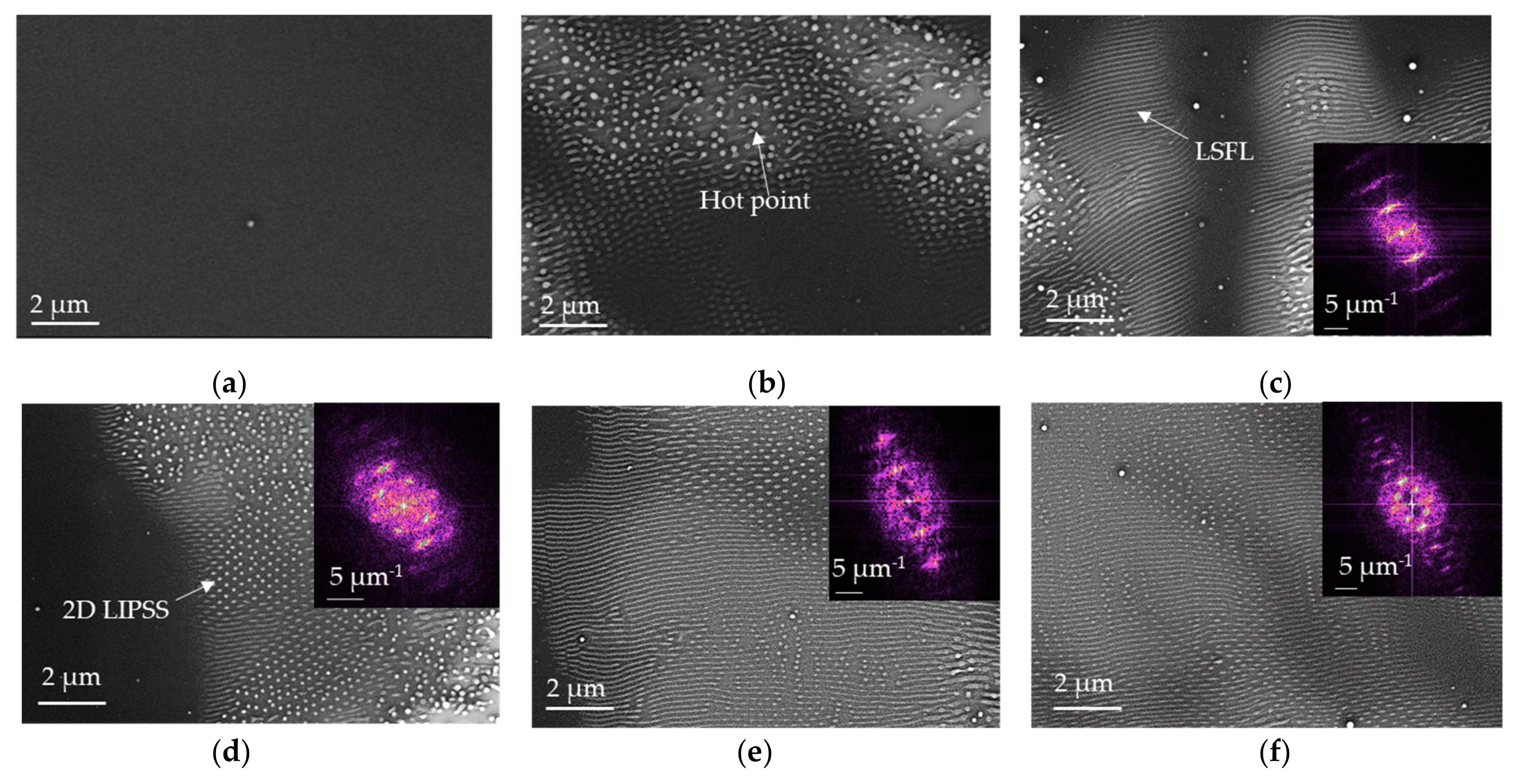
Figure 2 shows SEM micrographs of PS film before (Figure 2a) and after laser irradiation (Figure 2b–f) for 50 Hz of repetition rate, 8 µJ of pulse energy, and 11.8 mJ/cm2 of fluence per pulse. The generation of LIPSS structures in PS requires a minimum number of pulses to start the modification of the surface morphology. Within our experimental parameters, the first structures started to emerge from 5 × 10³ pulses (Figure 2b). These structures are probably formed around microscopic defects generation (hot points) and film roughness, as previously suggested [33]. These few-micrometers hot points grow and merge into larger areas. At N corresponding to 10 × 103 pulses, the micrographs reveal the formation of 1D periodic parallel structures (Figure 2c) that can be attributed to a low spatial-repetition rate LIPSS (LSFL). During the subsequent pulses, probably through the radiation–structuration feedback mechanisms, LSFL structures emerged as dominant structures. By further increasing the number of shots up to 15 × 103 shots, we observed nanodots structures with a 2D periodicity (2D-LIPSS) from Figure 2d. For the number of pulses between 15 × 103 and 35 × 103, LSFL and 2D-LIPSS were observed simultaneously within the same irradiation spot. From AFM analyses for the same samples characterized by SEM, the 2D Fast Fourier Transformation (FFT) was used in order to analyze the periodicities of LIPSS (Figure 2). From FFT analysis, we found that, for 10 × 103 pulses, LSFL has a period of Λ~165 nm, while above 15 × 103 pulses, the observed 2D-LIPSS exhibit a 2D periodicity of Λ1~165 nm and Λ2~230 nm. For 25 × 103 and 35 × 103 pulses (Figure 2e,f), from 2D-FFT analysis, the same 2D orientation and periodicity are observed.
From classical electromagnetic theory, it is known that the period, Λ, of the ripples depends on the laser wavelength, λ, effective refractive index, n, and the angle of incidence of the radiation, θ:
Λ = λ n ± sin θ
Thanks to the ellipsometric measurement, we found a refractive index of 1.57 for PS film at 266 nm, using Cauchy model. PS film was irradiated without tilting, and the calculated period of LIPSS corresponds to Λ~170 nm, confirming theoretical approach. This type of structure is induced by interference between incident wave and scattered and reflected waves that creates a modulation of the intensity of the beam in thin film.
Figure 3a,b presents AFM images of PS film after 35 × 103 pulses of laser irradiation and the corresponding cross-section profiles. Figure 3c displays a SEM micrograph of the tilted sample exhibiting ripples in the foreground and 2D-LIPSS in the background.
From AFM images on area 1 (Figure 3a), ripples with a typical height of 20 nm can be observed with some bendings and ramifications. The ramifications are characterized by the separation of the ripples into two or three separated ripples. These types of structures are associated with a spatial modulation of absorbed energy by defects on polystyrene thin film and superposition of the LIPSS wave vectors. The same types of structures were observed on silicon surface [46] and were explained by combining two-temperature model, free-carrier dynamics and Sipe’s theory [47].
From Figure 3b, another type of structure is observed on area 2, characterized by the formation of 2D-LIPSS within the ripples. From the AFM image, 2 periodicities can be observed with Λ1~340 nm and Λ2~165 nm. 2D LIPSSs with a typical height of 30 nm are formed inside parallel LSFL structures with a typical height of 13 nm. We suggest that formation of these nanodots is dominated by hydrodynamic instabilities, resulting in material redistribution from parallel ripples. We suppose that local instabilities are induced by surface-tension minimization that results in the ripple breaking into smaller parts. The viscosity of polymers is decreasing during irradiation, and hydrodynamic phenomenon starts to play a dominant role. The presence of two types of structures, namely ripples and nanodots, is the result of viscosity variations and a combination of broken and unbroken LSFL. Hexagonal lattice types have also been studied by M. Fermigier et al. [48], where the nonlinear growth of the Rayleigh–Taylor instability leads to the formation of two-dimensional patterns with hexagonal shape.
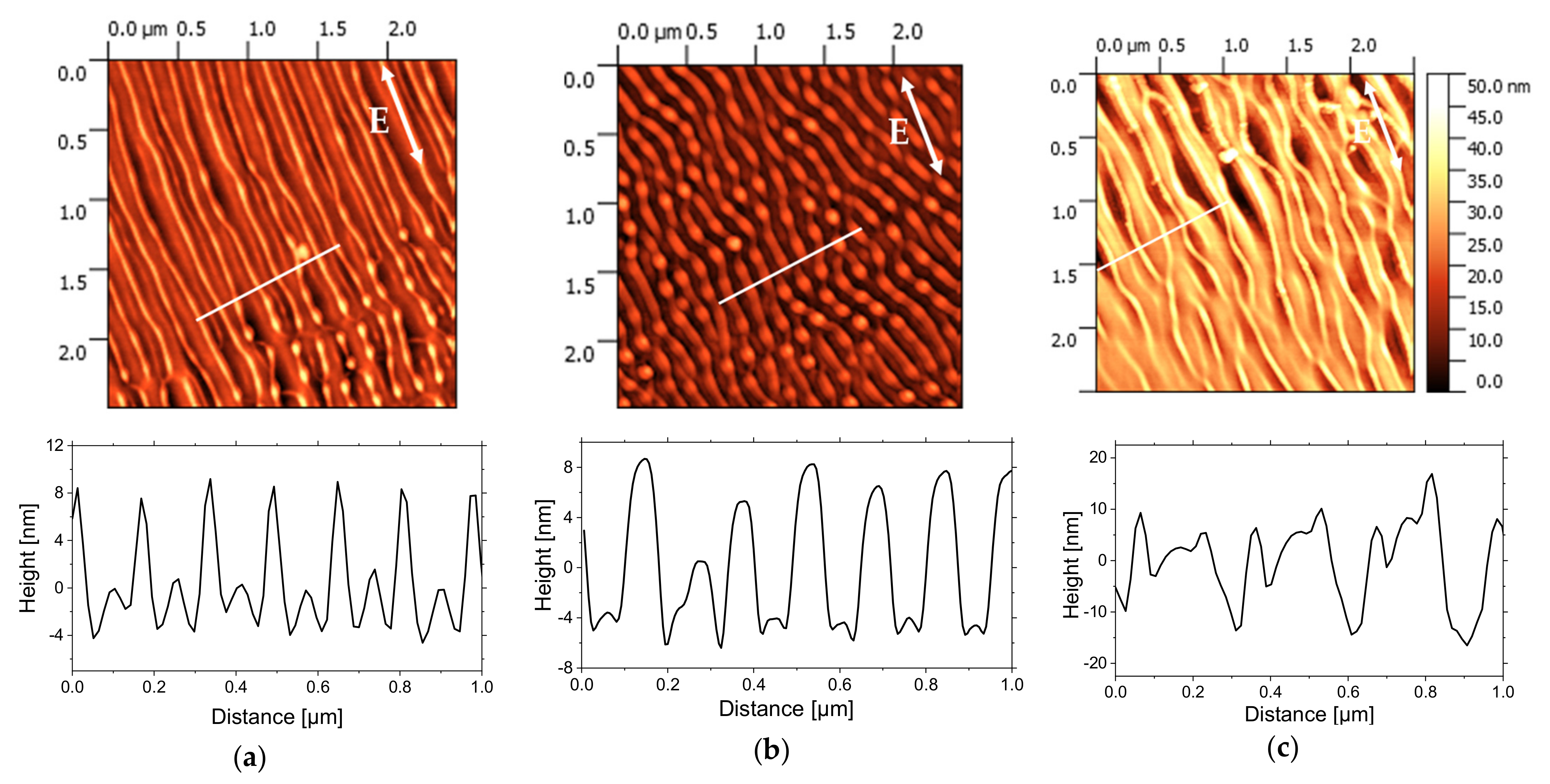
In order to produce the periodic structures at higher laser repetition rate and reduce the duration between pulses down to 1 ms, the irradiations were also carried out with the repetition rate of 1 kHz. Figure 4 displays AFM height images of 2.5 × 2.5 µm2 area of PS films irradiated with 50 × 103, 100 × 103, and 800 × 103 pulses for 0.6 mJ/cm2 of pulse fluence. For the lowest number of pulses (Figure 4a), first morphological changes are observed with the creation of periodic parallel structures. The period is Λ~170 nm, and the height of the structures is up to 10 nm. With the increasing of the pulses number up to 100 × 103, nanodots start to appear with the decreasing of the period Λ down to 150 nm. The height of these nanodots is around 10 nm. Finally, for an even higher number of pulses corresponding to 800 × 103 (Figure 4c), the parallel structures start to be distorted with the irradiated area exhibiting an array of like-groove morphologies. The distance between two consecutive grooves is around Λ~250 nm, and their depth is around 25 nm.
It was proposed by He and al. [46] that the quasi-periodic pattern of stripes on silicon is related to a spatial redistribution of the absorbed energy and to the formation of the regions where the absorbed fluence is not enough to induce effective ablation and could fuse the surface nanostructures leading to the progressive generation of the groove stripes covering the underlying ripples. We suppose that the same phenomenon was observed for PS film and reactions of photolysis are generated and induced the material loss. These photochemical reactions are characterized by much shorter time scales than thermal-related processes.
Based on Sipe’s theory [47], wave vectors are possible from LIPSS, depending on surface parameters (surface roughness and dielectric permittivity) and laser irradiation parameters. Once the LIPSSs are formed, surface roughness will induce the further enhancement of the ripples’ formation characterized by the redistribution of optical energy from subsequent laser pulses. In other words, we find the feedback effect, which explains the increase on the surface of the ripples. It is important to underline that the ripple formation is extended over a large area, and this is related to repeat scattering during multi-pulse irradiation, which can propagate the pattern.
Irradiation at 50 Hz can be compared with irradiation at 1 kHz, using the accumulated dose, which is the fluence per pulse times the number of pulses. The accumulated dose (60 J/cm2) at 50 Hz for 5 × 10³ pulses is the same as the one at 1 kHz for 100 × 103 pulses, and the accumulated dose (413 J/cm2) at 50 Hz for 35 × 103 pulses is similar as the one (480 J/cm2) at 1 kHz for 800 × 103 pulses.

3.2. Influence of the Substrate Temperature on the LIPSS Morphology

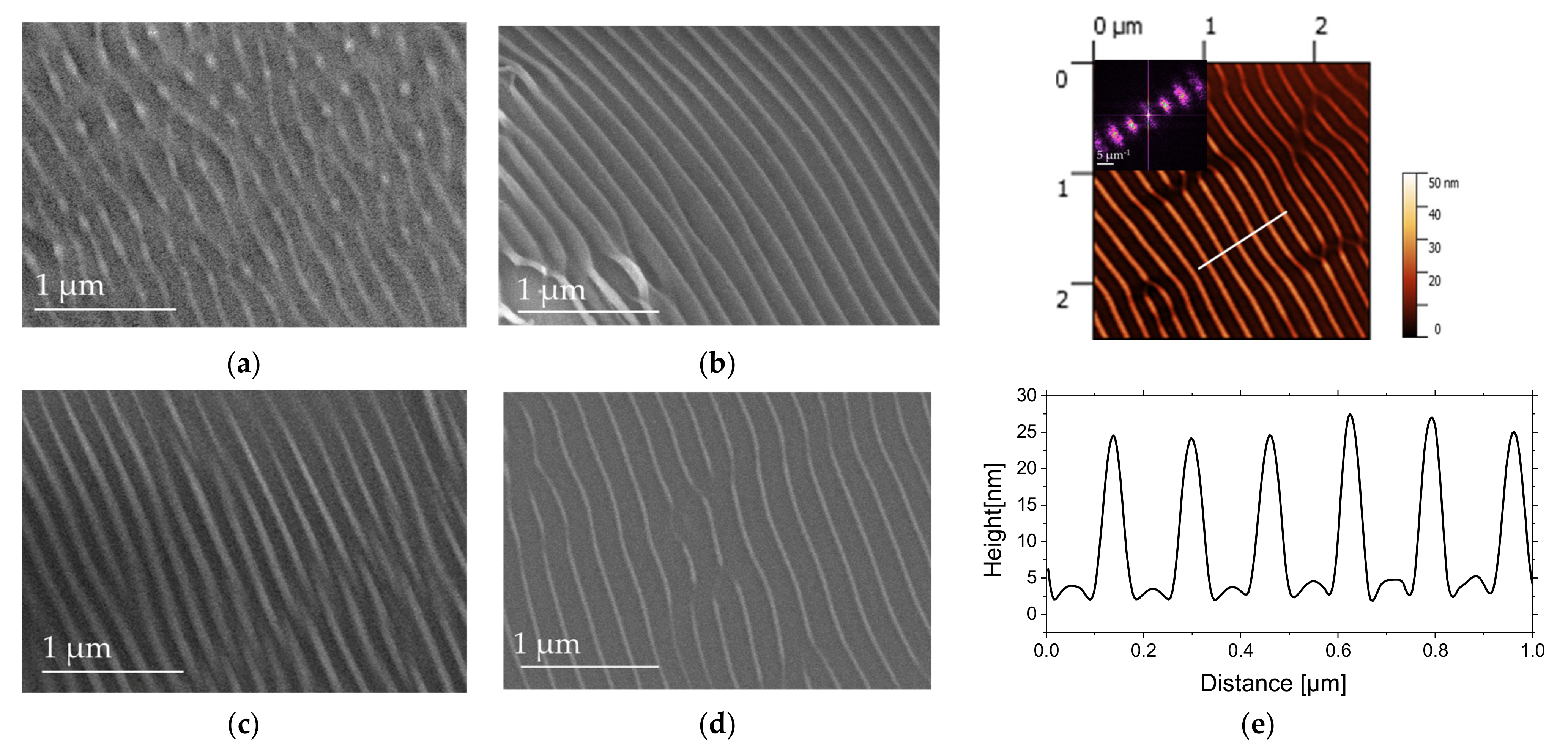
It is known that the behavior of polymers strongly depends on the temperature [49]. From a microscopic point of view, their behavior is associated with molecular relaxations and the elastic modulus decreases above Tg (here measured for PS bulk by DSC at 95 °C, in accordance with the value estimated by Vignaud et al. [50] at 97 °C for a PS 135 nm–thick layer). To investigate the influence of the substrate temperature, the ripples were generated with number of pulses N = 105, which is optimal for the formation of organized structures at a fixed fs-laser pulse fluence (F = 0.6 m J / cm 2 ) and laser repetition rate (1 kHz). This allowed us to create ripples parallel to the polarization vector. We varied the temperature of the Peltier module from RT to 97 °C, heating the polymer film during the irradiation. Figure 5 displays the corresponding SEM images. LSFLs are observed with the same period between ripples Λ~170 nm whatever the temperature of the substrate. However, the width of the ripples decreases from 80 nm at RT (Figure 5a) to 55 nm for 97 °C (Figure 5d). From AFM images, it could be seen that the height of the ripples was increased from 10 nm for RT (Figure 4b) to 20 nm for 97 °C (Figure 5e). The LIPSSs are formed independently of PS thickness, indicating that structuration process is significant only in the surface layer, which absorbs the light of the laser beam.
At low temperature corresponding to 23.5 °C, chains of the polymer are in a glassy state. Increasing of the temperature causes an increase in the mobility of macromolecular chains within thin film. The application of the laser energy at a temperature higher than RT can promote the passage of PS in soften state (Figure 5b) [51]. The softening of the PS makes hydrodynamic contributions, including thermo-capillary flow to the LSFL mechanisms, dominant, leading to higher and narrower ripples.

3.3. Scanning Processing

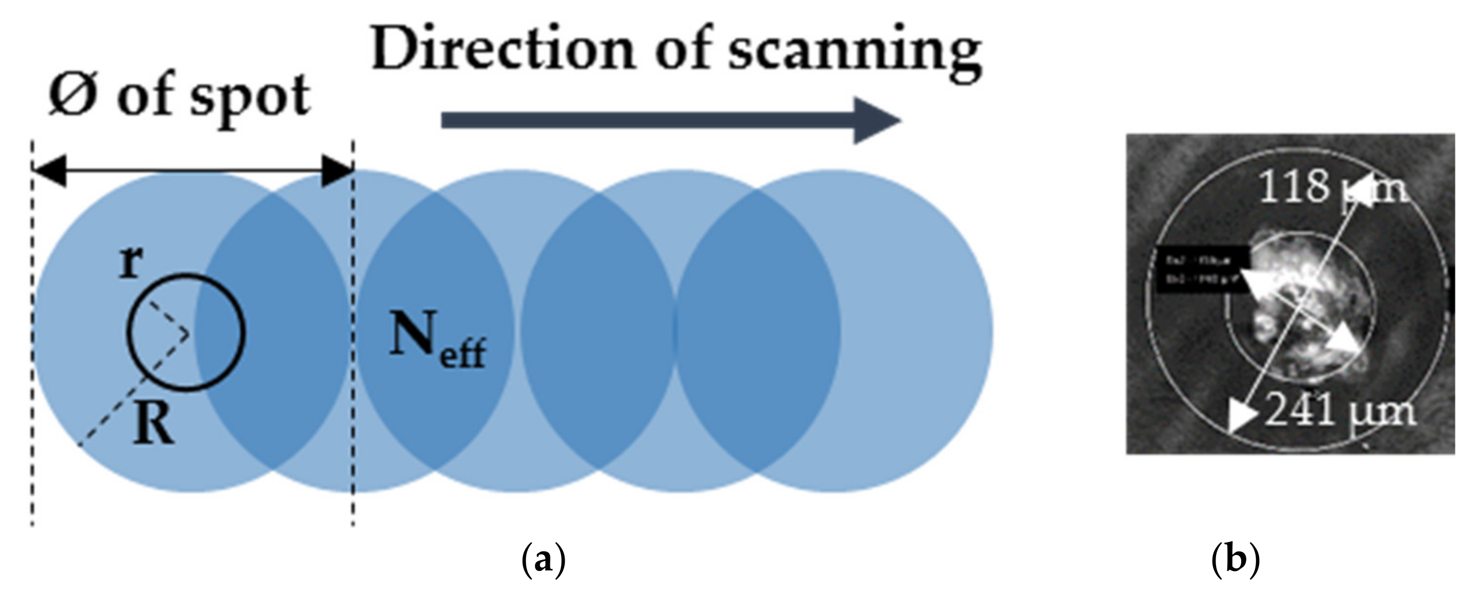
We also proceed to the LIPSS generation in scanning mode in order to create periodic structures on large area. In order to optimize the scanning time, we approached the substrate towards the FoF position to z = 68.5 mm from the focusing laser lens. Figure 6a illustrates the beam overlap during the scanning process. There are two zones in the laser spot to be consider, as shown in Figure 6b: The first one in the middle of the laser spot, with a diameter equal to 2r, is the zone where there are many photons interacting with the PS layer and where soft ablation can take place in relation to the Gaussian beam shape. There is also the weak zone of interaction of the laser beam with the layer, with the outer diameter 2R.
For this, the scanning was carried out at different speeds, ν, for a repetition rate, ω, corresponding to 1 kHz, which then defines a number of effectives pulses, Neff, that applied during the overlap of two laser spots with their diameters, Ø, corresponding to 241 µm:
N eff = Ø ω ν
The average number of laser pulses in overlapping area was thus ranged from 2410 to 12,050 by varying the scanning speed of the laser beam from 20 to 100 μm/s at fixed fluence corresponding to 2.2 mJ/cm2.
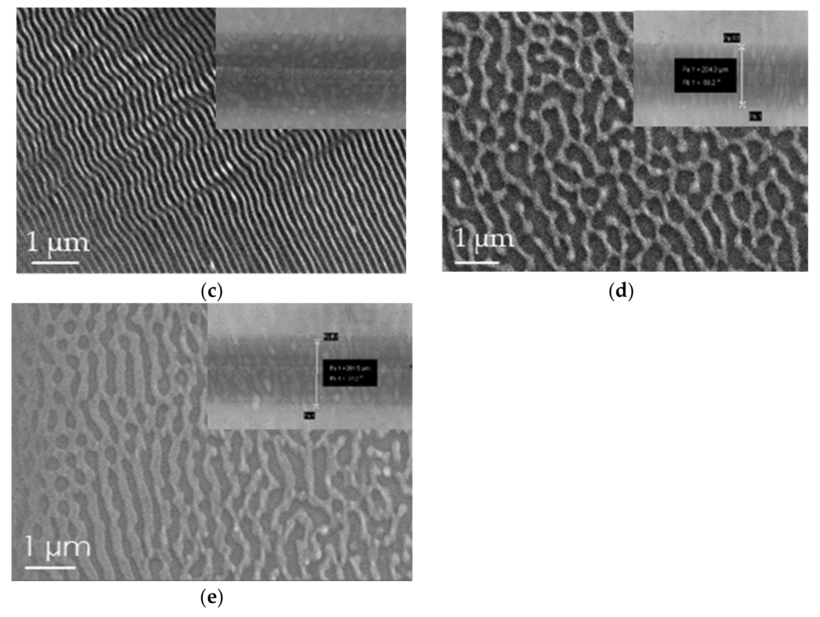
Figure 7 presents SEM images of the formed structures. At the microscopic scale, the periodic parallel structures for 20 µm/s are created with Λ~170 nm (Figure 7a). At low scanning speed, a soft ablative regime dominates in the center of the spot with the LIPSS generation around this area. By increasing the speed until 40 µm/s, the polymer is less affected in central part of laser impact (Figure 7b). For a scanning speed of 60 μm/s, the quasi-parallel ripples are dominant and cover a large area of scanning line (Figure 7c). Higher speeds (80 and 100 µm/s) lead to the same result, with observed quasi-periodic structures with higher period (Figure 7d. This is related to the fact that the effective number of pulses of the laser beam in the overlap zone is not sufficient to induce the LIPSS.
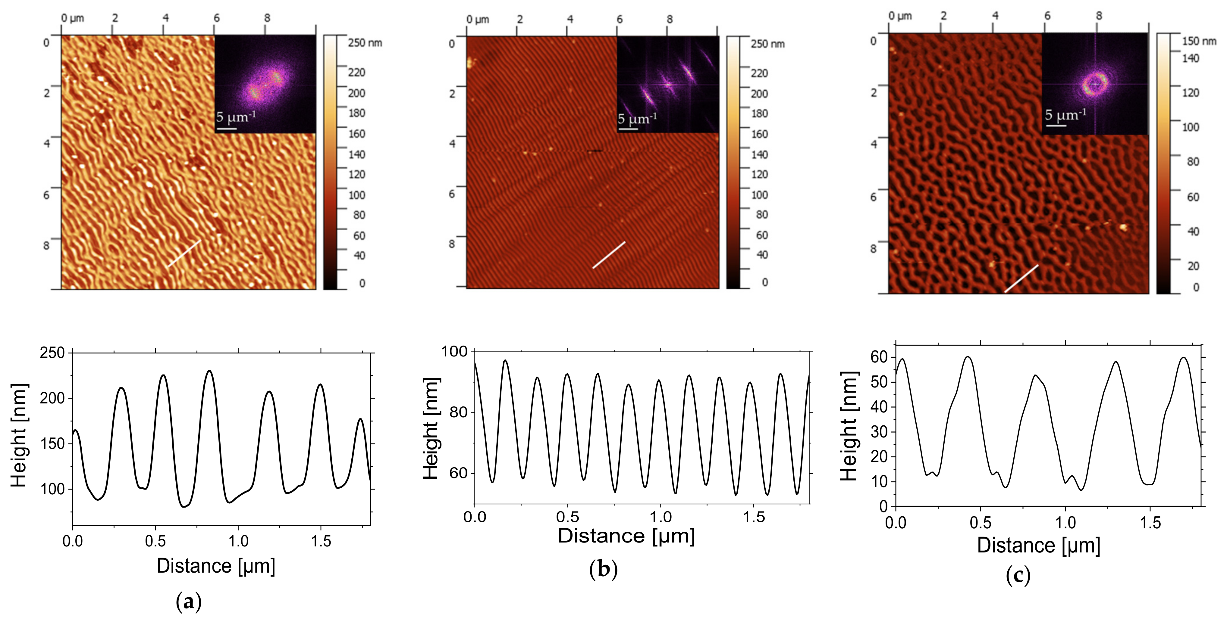
From AFM images (Figure 8a–c) and corresponding 2D-FFT image analyses, it can be seen that, at a lower scanning speed corresponding to 20 µm/s (with Neff = 12,050), the structures are linearly oriented with height H~130 nm but partially destructed. This could relate to the material loss due to the photochemical reactions initiated by the absorption of energy of laser beam with the creation of transient excited states and future consequence of bond breaking and radicalization. For a scanning speed of 60 µm/s, well-defined and periodic LSFLs are observed. The height of ripples is about 35 nm, which could be related to the material redistribution with modulated energy deposition but not material loss. When radiation order couples with the surface structure order, one enhances the other, and periodic structures grow faster than disordered ones and emerge as a dominant surface feature. The generation of higher-order harmonics from 2D-FFT analysis highlights the good quality and homogeneity of the ripples on large areas for this scanning speed with the period of Λ~170 nm and the height of H~35 nm. A scanning speed of 80 µm/s leads mostly to an elliptic profile of 2D-FFT, with a higher period corresponding to 400 nm.
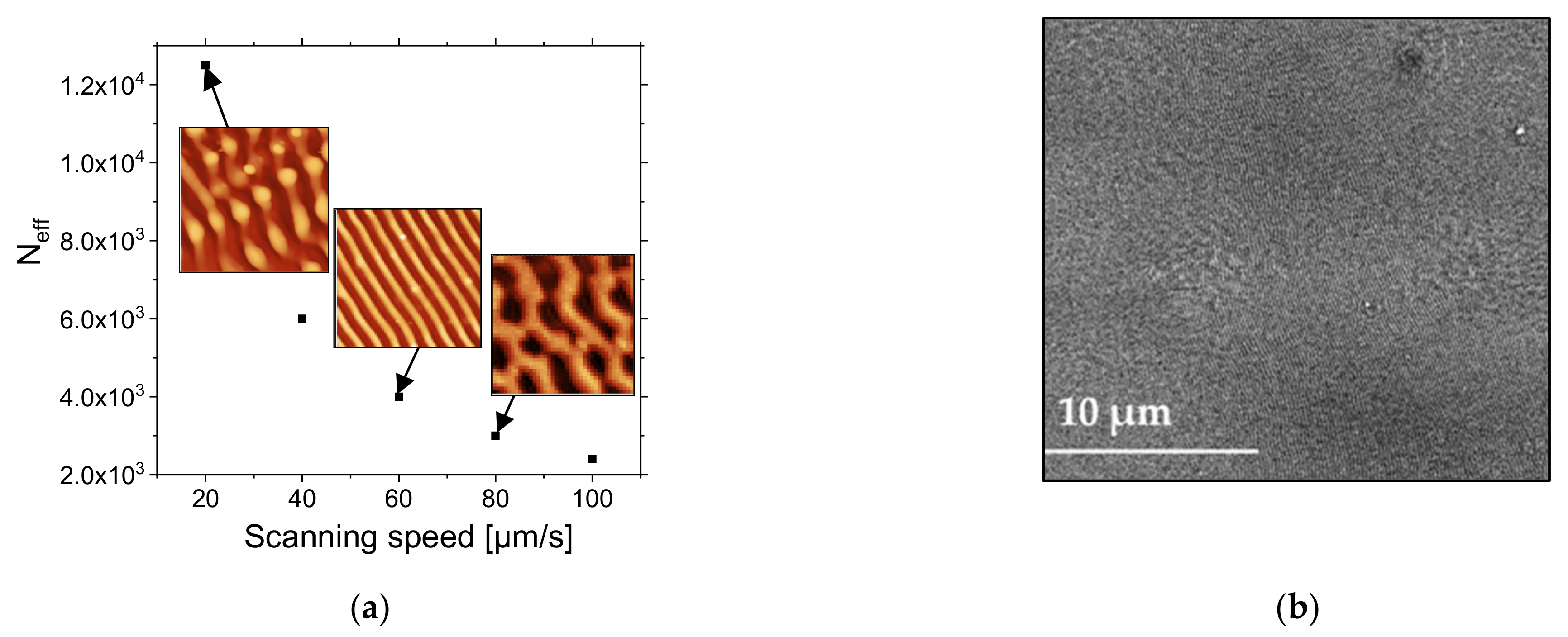
As shown in Figure 9a, the effective number of pulses decreases from 2410 to 12,050 when the scanning speed increases from 20 to 100 µm/s. The conditions for well-defined and organized LIPSS were optimal for an effective number of pulses of 4000 for a pulse fluence of 2.2 mJ/cm2. These conditions allowed us to obtain LIPSS without any defect, except for bending over a large area, as shown in Figure 9b. The size of the area is limited by the size of the scanning area. The test was performed over 4 × 4 mm2.

4. Conclusions

We performed PS thin films nanostructuring by UV femtosecond laser beam at 266 nm, with two repetitions rates corresponding to 50 and 1000 Hz. For 50 Hz of repetition rate and 11.8 mJ/cm2 of fluence per pulse, parallel LSFL structures were observed above 103 pulses structures with a period Λ smaller than the laser irradiation wavelength λ. Ramifications and bendings of ripples were also observed, and they are probably associated with the spatial modulation of the absorbed energy by PS-thin-film defects on polystyrene thin film. Two-dimensional LIPSS structures started to appear for pulse numbers greater than 15 × 103. For 1 kHz of repetition rate, 0.6 mJ/cm2 of fluence per pulse and a number of pulses between 50 × 103 and 800 × 103, we found parallel structures LSFL with the period close to 170 nm and less than the beam wavelength. For 800 × 103 pulses, the ripples started to be destroyed with the formation of the groove-like morphology with a spatial period of 260 nm. Scanning the PS film with the laser beam also generated LIPSS on large areas, and we found that 60 µm/s was the optimal speed for the creation of well-resolved ripples for a 2.2 mJ/cm2 of fluence per pulse.
Finally, we demonstrated that heating the PS films from RT up to 97 °C upon femtosecond laser irradiation simultaneously induced the ripples’ width decrease and amplitude increase.

Author Contributions

O.S., H.R., M.V., A.P., C.S. and N.S., conceived of and realized the experiments, and wrote the manuscript. All authors have read and agreed to the published version of the manuscript.

Funding

This research received funding from Region Centre-Val-de-Loire (French Government) through the national project APR-IA number 201900134921.

Data Availability Statement

The data is included in the main text.

Acknowledgments

This work is part of a National Project entitled “APR-IA CoMeMAT” funded by the Region Centre-Val-de-Loire.

Conflicts of Interest

The authors declare no conflict of interest.

References

  1. Bucknal, D.G. Nanolithography and Patterning Techniques in Microelectronics; CRC Press: Boca Raton, FL, USA, 2005. [Google Scholar]
  2. Dewan, R.; Knipp, D. Light trapping in thin-film silicon solar cells with integrated diffraction grating. J. Appl. Phys. 2009, 106, 23058–23065. [Google Scholar] [CrossRef]
  3. Hauser, H.; Tucher, N.; Tokai, K.; Schneider, P.; Wellens, C.; Volk, A.K.; Seitz, S.; Benick, J.; Barke, S.; Dimroth, F.; et al. Development of nanoimprint processes for photovoltaic applications. J. Micro/Nanolithography MEMS MOEMS 2015, 14, 031210. [Google Scholar] [CrossRef] [Green Version]
  4. Ranc, H.; Servais, C.; Chauvy, P.-F.; Debaud, S.; Mischler, S. Effect of surface structure on frictional behaviour of a tongue/palate tribological system. Tribol. Int. 2006, 39, 1518–1526. [Google Scholar] [CrossRef]
  5. Bienaime, A.; Elie-Caille, C.; Leblois, T. Micro Structuration of GaAs Surface by Wet Etching: Towards a Specific Surface Behavior. J. Nanosci. Nanotechnol. 2012, 12, 6855–6863. [Google Scholar] [CrossRef]
  6. Cui, Y.; Phang, I.Y.; Lee, Y.H.; Lee, M.R.; Zhang, Q.; Ling, X.Y. Multiplex plasmonic anti-counterfeiting security labels based on surface-enhanced Raman scattering. Chem. Commun. 2015, 51, 5363–5366. [Google Scholar] [CrossRef]
  7. Cattoni, A.; Chen, J.; Decanini, D.; Shi, J.; Haghiri-Gosnet, A.-M. Soft UV Nanoimprint Lithography: A Versatile Tool for Nanostructuration at the 20nm Scale. In Recent Advances in Nanofabrication Techniques and Applications; IntechOpen: London, UK, 2011. [Google Scholar] [CrossRef] [Green Version]
  8. Pimpin, A.; Srituravanich, W. Review on Micro- and Nanolithography Techniques and their Applications. Eng. J. 2012, 16, 37–55. [Google Scholar] [CrossRef] [Green Version]
  9. Yang, L.; Wei, J.; Ma, Z.; Song, P.; Ma, J.; Zhao, Y.; Huang, Z.; Zhang, M.; Yang, F.; Wang, X. The Fabrication of Micro/Nano Structures by Laser Machining. Nanomaterials 2019, 9, 1789. [Google Scholar] [CrossRef] [Green Version]
  10. Ruffino, F.; Grimaldi, M.G. Nanostructuration of Thin Metal Films by Pulsed Laser Irradiations: A Review. Nanomaterials 2019, 9, 1133. [Google Scholar] [CrossRef] [Green Version]
  11. Peter, A.; Lutey, A.H.; Faas, S.; Romoli, L.; Onuseit, V.; Graf, T. Direct laser interference patterning of stainless steel by ultrashort pulses for antibacterial surfaces. Opt. Laser Technol. 2020, 123, 105954. [Google Scholar] [CrossRef]
  12. Gnilitskyi, I.; Derrien, T.J.-Y.; Levy, Y.; Bulgakova, N.M.; Mocek, T.; Orazi, L. High-speed manufacturing of highly regular femtosecond laser-induced periodic surface structures: Physical origin of regularity. Sci. Rep. 2017, 7, 8485. [Google Scholar] [CrossRef] [Green Version]
  13. Bonse, J. Quo Vadis LIPSS?—Recent and Future Trends on Laser-Induced Periodic Surface Structures. Nanomaterials 2020, 10, 1950. [Google Scholar] [CrossRef]
  14. Alves-Lopes, I.; Almeida, A.; Oliveira, V.; Vilar, R. Influence of Femtosecond Laser Surface Nanotexturing on the Friction Behavior of Silicon Sliding Against PTFE. Nanomaterials 2019, 9, 1237. [Google Scholar] [CrossRef] [Green Version]
  15. Liu, Y.-H.; Yeh, S.-C.; Cheng, C.-W. Two-Dimensional Periodic Nanostructure Fabricated on Titanium by Femtosecond Green Laser. Nanomaterials 2020, 10, 1820. [Google Scholar] [CrossRef]
  16. Huynh, T.T.D.; Vayer, M.; Sauldubois, A.; Petit, A.; Semmar, N. Evidence of liquid phase during laser-induced periodic surface structures formation induced by accumulative ultraviolet picosecond laser beam. Appl. Phys. Lett. 2015, 107, 193105. [Google Scholar] [CrossRef]
  17. Huynh, T.T.D.; Petit, A.; Semmar, N. Picosecond laser induced periodic surface structure on copper thin films. Appl. Surf. Sci. 2014, 302, 109–113. [Google Scholar] [CrossRef]
  18. Huynh, T.T.D.; Semmar, N. Dependence of ablation threshold and LIPSS formation on copper thin films by accumulative UV picosecond laser shots. Appl. Phys. A 2014, 116, 1429–1435. [Google Scholar] [CrossRef]
  19. Yang, Z.; Zhu, C.; Zheng, N.; Le, D.; Zhou, J. Superhydrophobic Surface Preparation and Wettability Transition of Titanium Alloy with Micro/Nano Hierarchical Texture. Materials 2018, 11, 2210. [Google Scholar] [CrossRef] [PubMed] [Green Version]
  20. Talbi, A.; Semmar, N.; Tabbal, M.; Connor, G.O.; Coddet, P.; Thomann, A.-L.; Stolz, A.; Leborgne, C.; Millon, E. Femtosecond laser irradiation of titanium oxide thin films: Accumulation effect under IR beam. Appl. Phys. A 2020, 126, 390. [Google Scholar] [CrossRef]
  21. Talbi, A.; Tameko, C.T.; Stolz, A.; Millon, E.; Boulmer-Leborgne, C.; Semmar, N. Nanostructuring of titanium oxide thin film by UV femtosecond laser beam: From one spot to large surfaces. Appl. Surf. Sci. 2017, 418, 425–429. [Google Scholar] [CrossRef]
  22. Talbi, A.; Kaya-Boussougou, S.; Sauldubois, A.; Stolz, A.; Boulmer-Leborgne, C.; Semmar, N. Laser-induced periodic surface structures formation on mesoporous silicon from nanoparticles produced by picosecond and femtosecond laser shots. Appl. Phys. A 2017, 123. [Google Scholar] [CrossRef]
  23. Talbi, A.; Petit, A.; Melhem, A.; Stolz, A.; Boulmer-Leborgne, C.; Gautier, G.; Defforge, T.; Semmar, N. Nanoparticles based laser-induced surface structures formation on mesoporous silicon by picosecond laser beam interaction. Appl. Surf. Sci. 2016, 374, 31–35. [Google Scholar] [CrossRef]
  24. Liu, M.-N.; Wang, L.; Yu, Y.-H.; Li, A.-W. Biomimetic construction of hierarchical structures via laser processing. Opt. Mater. Express 2017, 7, 2208. [Google Scholar] [CrossRef]
  25. Costache, F.; Henyk, M.; Reif, J. Surface patterning on insulators upon femtosecond laser ablation. Appl. Surf. Sci. 2003, 208–209, 486–491. [Google Scholar] [CrossRef]
  26. Rebollar, E.; Ezquerra, T.A.; Nogales, A. Laser-induced periodic surface structures (Lipss) on polymer surfaces. Wrinkled Polym. Surf. Strateg. Methods Appl. 2019, 143–155. [Google Scholar] [CrossRef]
  27. Emmony, D.C.; Howson, R.P.; Willis, L.J. Laser mirror damage in germanium at 10.6 μm. Appl. Phys. Lett. 1973, 23, 598–600. [Google Scholar] [CrossRef]
  28. Le Harzic, R.; Dörr, D.; Sauer, D.; Stracke, F.; Zimmermann, H. Generation of high spatial frequency ripples on silicon under ultrashort laser pulses irradiation. Appl. Phys. Lett. 2011, 98, 2009–2012. [Google Scholar] [CrossRef]
  29. Miyaji, G.; Miyazaki, K. Origin of periodicity in nanostructuring on thin film surfaces ablated with femtosecond laser pulses. Opt. Express 2008, 16, 16265. [Google Scholar] [CrossRef]
  30. Young, J.F.; Sipe, J.E.; Van Driel, H.M. Laser-induced periodic surface structure. III. Fluence regimes, the role of feedback, and details of the induced topography in germanium. Phys. Rev. B 1984, 30, 2001. [Google Scholar] [CrossRef]
  31. Rebollar, E.; Castillejo, M.; Ezquerra, T.A. Laser induced periodic surface structures on polymer films: From fundamentals to applications. Eur. Polym. J. 2015, 73, 162–174. [Google Scholar] [CrossRef] [Green Version]
  32. Rebollar, E.; Hernández, M.; Sanz, M.; Pérez, S.; Ezquerra, T.A.; Castillejo, M. Laser-induced surface structures on gold-coated polymers: Influence of morphology on surface-enhanced Raman scattering enhancement. J. Appl. Polym. Sci. 2015, 132, 2–7. [Google Scholar] [CrossRef] [Green Version]
  33. Goya, K.; Yamachoshi, Y.; Fuchiwaki, Y.; Tanaka, M.; Ooie, T.; Abe, K.; Kataoka, M. Femtosecond laser direct fabrication of micro-grooved textures on a capillary flow immunoassay microchip for spatially-selected antibody immobilization. Sens. Actuators B 2017, 239, 1275–1281. [Google Scholar] [CrossRef]
  34. Wang, B.; Wang, X.C.; Zheng, H.Y.; Lam, Y.C. Femtosecond laser-induced surface wettability modification of polystyrene surface. Sci. China Phys. Mech. Astron. 2016, 59, 124211. [Google Scholar] [CrossRef]
  35. Sarbada, S.; Shin, Y.C. Superhydrophobic contoured surfaces created on metal and polymer using a femtosecond laser. Appl. Surf. Sci. 2017, 405, 465–475. [Google Scholar] [CrossRef]
  36. Fan, W.; Qian, J.; Bai, F.; Li, Y.; Wang, C.; Zhao, Q.-Z. A facile method to fabricate superamphiphobic polytetrafluoroethylene surface by femtosecond laser pulses. Chem. Phys. Lett. 2016, 644, 261–266. [Google Scholar] [CrossRef]
  37. Riveiro, A.; Soto, R.; Comesaña, R.; Boutinguiza, M.; del Val, J.; Quintero, F.; Lusquiños, F.; Pou, J. Laser surface modification of PEEK. Appl. Surf. Sci. 2012, 258, 9437–9442. [Google Scholar] [CrossRef]
  38. Riveiro, A.; Maçon, A.L.B.; Val, J.; Comesaña, R.; Pou, J. Laser Surface Texturing of Polymers for Biomedical Applications. Front. Phys. 2018, 6. [Google Scholar] [CrossRef]
  39. Rebollar, E.; Pérez, S.; Hernández, J.J.; Martín-Fabiani, I.; Rueda, D.R.; Ezquerra, T.A.; Castillejo, M. Assessment and Formation Mechanism of Laser-Induced Periodic Surface Structures on Polymer Spin-Coated Films in Real and Reciprocal Space. Langmuir 2011, 27, 5596–5606. [Google Scholar] [CrossRef] [Green Version]
  40. Barb, R.-A.; Hrelescu, C.; Dong, L.; Heitz, J.; Siegel, J.; Slepička, P.; Vosmanská, V.; Svorcik, V.; Magnus, B.; Marksteiner, R.; et al. Laser-induced periodic surface structures on polymers for formation of gold nanowires and activation of human cells. Appl. Phys. A 2014, 117, 295–300. [Google Scholar] [CrossRef]
  41. Rebollar, E.; De Aldana, J.R.V.; Pérez-Hernández, J.A.; Ezquerra, T.A.; Moreno, P.; Castillejo, M. Ultraviolet and infrared femtosecond laser induced periodic surface structures on thin polymer films. Appl. Phys. Lett. 2012, 100, 041106. [Google Scholar] [CrossRef] [Green Version]
  42. Daskalova, A.; Bliznakova, I.; Angelova, L.; Trifonov, A.; Declercq, H.; Buchvarov, I. Femtosecond Laser Fabrication of Engineered Functional Surfaces based on Biodegradable Polymer and Biopolymer/Ceramic Composite Thin Films. Polymers 2019, 11, 378. [Google Scholar] [CrossRef] [Green Version]
  43. Rebollar, E.; De Aldana, J.R.V.; Martín-Fabiani, I.; Hernández, M.; Rueda, D.R.; Ezquerra, T.A.; Domingo, C.; Moreno, P.; Castillejo, M. Assessment of femtosecond laser induced periodic surface structures on polymer films. Phys. Chem. Chem. Phys. 2013, 15, 11287–11298. [Google Scholar] [CrossRef] [PubMed] [Green Version]
  44. Ionin, A.A.; Kudryashov, S.I.; Ponomarev, Y.N.; Seleznev, L.V.; Sinitsyn, D.V.; Tikhomirov, B.A.; Phipps, C. Non-linear Absorption and Ionization of Gases by Intense Femtosecond Laser Pulses. AIP Conf. Proc. 2010, 1278, 354–363. [Google Scholar] [CrossRef]
  45. Talbi, A. Effect Of Ultra-Short Laser Nanostructuring Of Material Surfaces On The Evolution Of Their Thermoelectric Properties. Ph.D. Thesis, Université d’Orléans, Orléans, France, 2018. [Google Scholar]
  46. He, S.; Nivas, J.J.; Anoop, K.; Vecchione, A.; Hu, M.; Bruzzese, R.; Amoruso, S. Surface structures induced by ultrashort laser pulses: Formation mechanisms of ripples and grooves. Appl. Surf. Sci. 2015, 353, 1214–1222. [Google Scholar] [CrossRef]
  47. Sipe, J.E.; Young, J.F.; Preston, J.S. Laser-induced periodic surface structure. I. Theory. Phys. Rev. B 1983, 27, 1141–1154. [Google Scholar] [CrossRef]
  48. Fermigier, M.; Limat, L.; Wesfreid, J.E.; Boudinet, P.; Quilliet, C. Two-dimensional patterns in Rayleigh-Taylor instability of a thin layer. J. Fluid Mech. 1992, 236, 83. [Google Scholar] [CrossRef]
  49. Richeton, J.; Ahzi, S.; Vecchio, K.; Jiang, F.; Adharapurapu, R. Influence of temperature and strain rate on the mechanical behavior of three amorphous polymers: Characterization and modeling of the compressive yield stress. Int. J. Solids Struct. 2006, 43, 2318–2335. [Google Scholar] [CrossRef] [Green Version]
  50. Vignaud, G.; Chebil, M.S.; Bal, J.K.; Delorme, N.; Beuvier, T.; Grohens, Y.; Gibaud, A. Densification and Depression in Glass Transition Temperature in Polystyrene Thin Films. Langmuir 2014, 30, 11599–11608. [Google Scholar] [CrossRef]
  51. Bodiguel, H.; Frétigny, C. Viscoelastic Properties of Ultrathin Polystyrene Films. Macromolecules 2007, 40, 7291–7298. [Google Scholar] [CrossRef]
Figure 1. Schematics of PS laser surface structuring steps: (a) preparation of polymer solution by dissolution of the polymer in solvent, (b) spin-coating of polymer solution onto silicon substrate to obtain a supported polymer film, (c) irradiation of polymer film by fs laser, and (d) laser-beam focus using a focal lens.
Nanomaterials 11 01060 g001
Figure 2. SEM micrographs of PS film with corresponding FFT images from AFM analysis: (a) before and after laser irradiation at pulse fluence F = 11.8 mJ/cm2, repetition rate of 50 Hz for pulse number N: (b) 5 × 10³, (c) 10 × 103, (d) 15 × 103, (e) 25 × 103, and (f) 35 × 103.
Nanomaterials 11 01060 g002
Figure 3. AFM height (amplitude) images and cross-section profiles along the corresponding lines (2.5 × 2.5 µm2 size, Z scale is 50 nm) of PS film irradiated at 266 nm, at a repetition rate of 50 Hz, a fluence of 11.8 mJ/cm2, after 35 × 103 pulses: (a) area 1, (b) area 2, and (c) SEM image. The polarization direction of the laser beam is indicated by double arrows.
Nanomaterials 11 01060 g003
Figure 4. AFM height images (2.5 × 2.5 µm2 size) and cross-sections profiles along the corresponding white lines of PS films irradiated at 266 nm, 1 kHz of repetition rate, and at F = 0.6 m J / cm 2 , with number of pulses, N, (a) 50 × 103, (b) 100 × 103, and (c) 800 × 103. The polarization direction of the laser beam is indicated by double arrows.
Nanomaterials 11 01060 g004
Figure 5. SEM images of PS film irradiated at λ = 266 nm,1 kHz of repetition rate and pulse fluence F = 0.6 m J / cm 2 with 105 pulses at (a) 23.5 °C, (b) 40 °C, (c) 60 °C, and (d) 97 °C. (e) AFM height image (2.5 × 2.5 µm2 size) of PS film irradiated at 266 nm, 1 kHz of repetition rate with number of pulses N = 100 × 103 at 97 °C, and cross-section profile along the white line.
Nanomaterials 11 01060 g005
Figure 6. (a) Schematic of the beam overlap during a scanning process. (b) SEM image of laser impact on PS film irradiated at 266 nm at the repetition rate of 1 kHz at z = 68.5 mm.
Nanomaterials 11 01060 g006
Figure 7. SEM images of PS film irradiated at λ = 266 nm at frequency of 1 kHz and pulse fluence of 2.2 m J / cm 2 at different scanning speeds: (a) 20, (b) 40, (c) 60, (d) 80, and (e) 100 μm/s.
Nanomaterials 11 01060 g007aNanomaterials 11 01060 g007b
Figure 8. AFM height images (10 × 10 µm2 size) and corresponding 2D-FFT scattering graphs of PS film irradiated at λ of 266 nm with repetition rate of 1 kHz and a pulse fluence of 2.2 m J / cm 2 , at scanning speeds (a) 20, (b) 60, and (c) 80 µm/s.
Nanomaterials 11 01060 g008
Figure 9. (a) Average effective number Neff of pulses at overlapping area as a function of scanning speed (from 20 to 100 µm/s). (b) SEM image of PS film irradiated at λ 266 nm, with a repetition rate of 1 kHz and a pulse fluence of 2.2 m J / cm 2 at a 60 µm/s scanning speed.
Nanomaterials 11 01060 g009
Publisher’s Note: MDPI stays neutral with regard to jurisdictional claims in published maps and institutional affiliations.