
Carbon-Nanotube-Coated Surface Electrodes for Cortical Recordings In Vivo

 ,
,  , and
, and 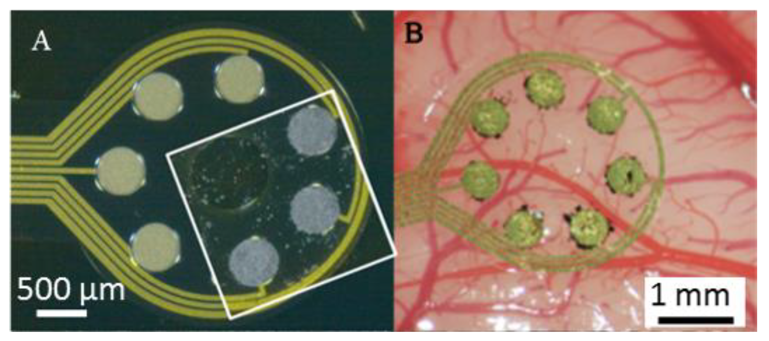
Abstract
1. Introduction
1.1. The Requirement of Small Electrode Contact Diameters
1.2. Applications of CNTs to Improve Effective Electrode Contact Surface Areas
1.3. The CNT-Coated Surface Electrode
2. Materials and Methods
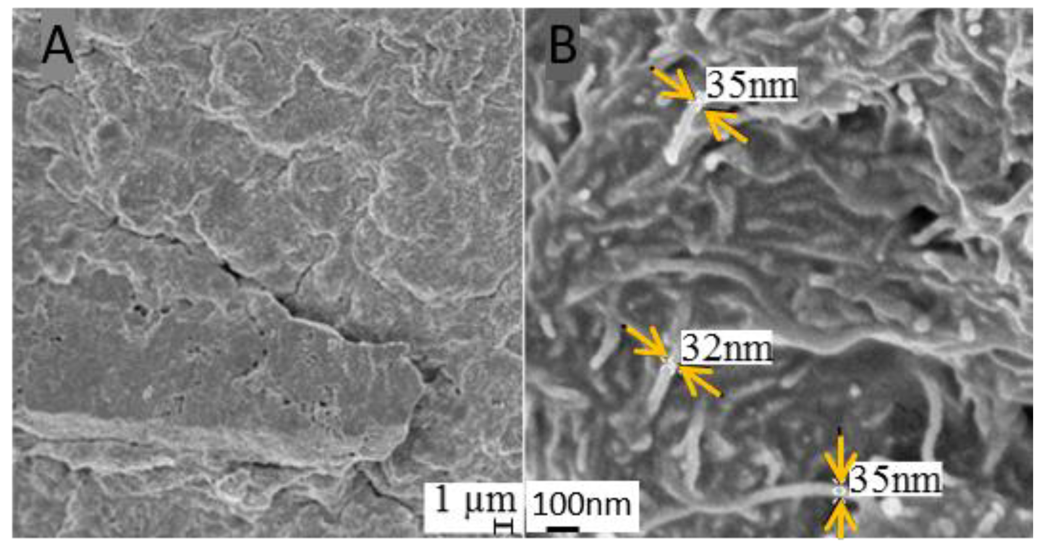
2.1. CNT-Coated ECoC Electrodes
2.2. In Vivo Recordings
2.3. Statistics
3. Results
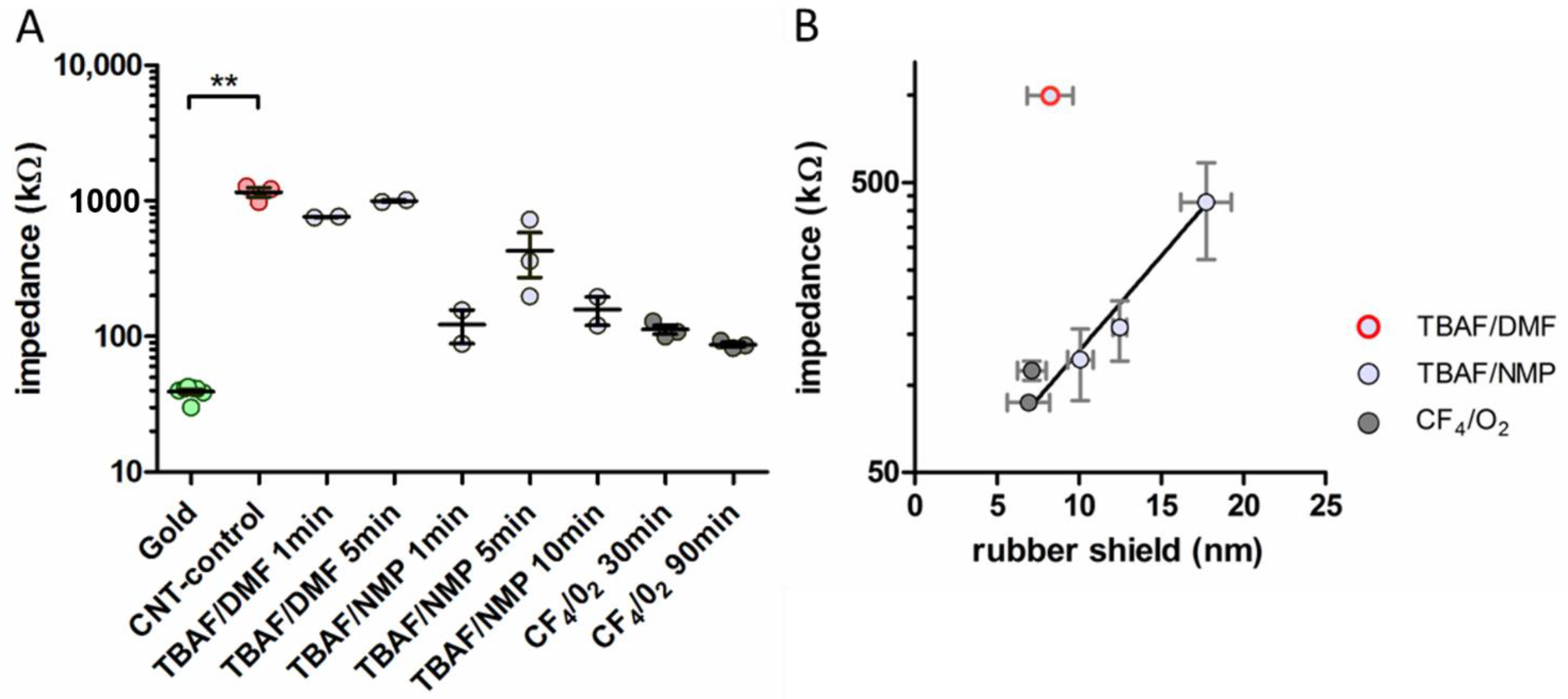
3.1. Impedances
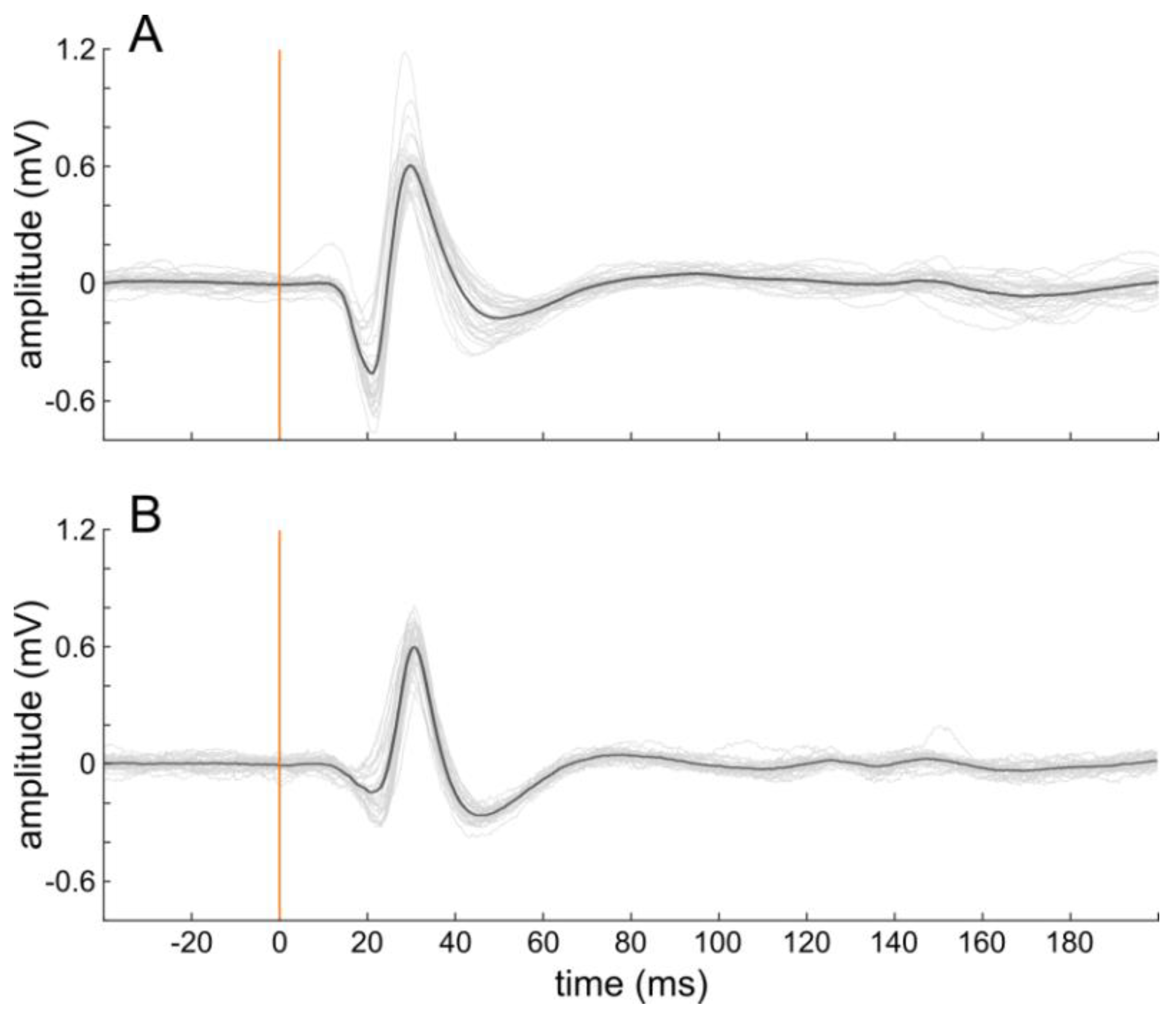
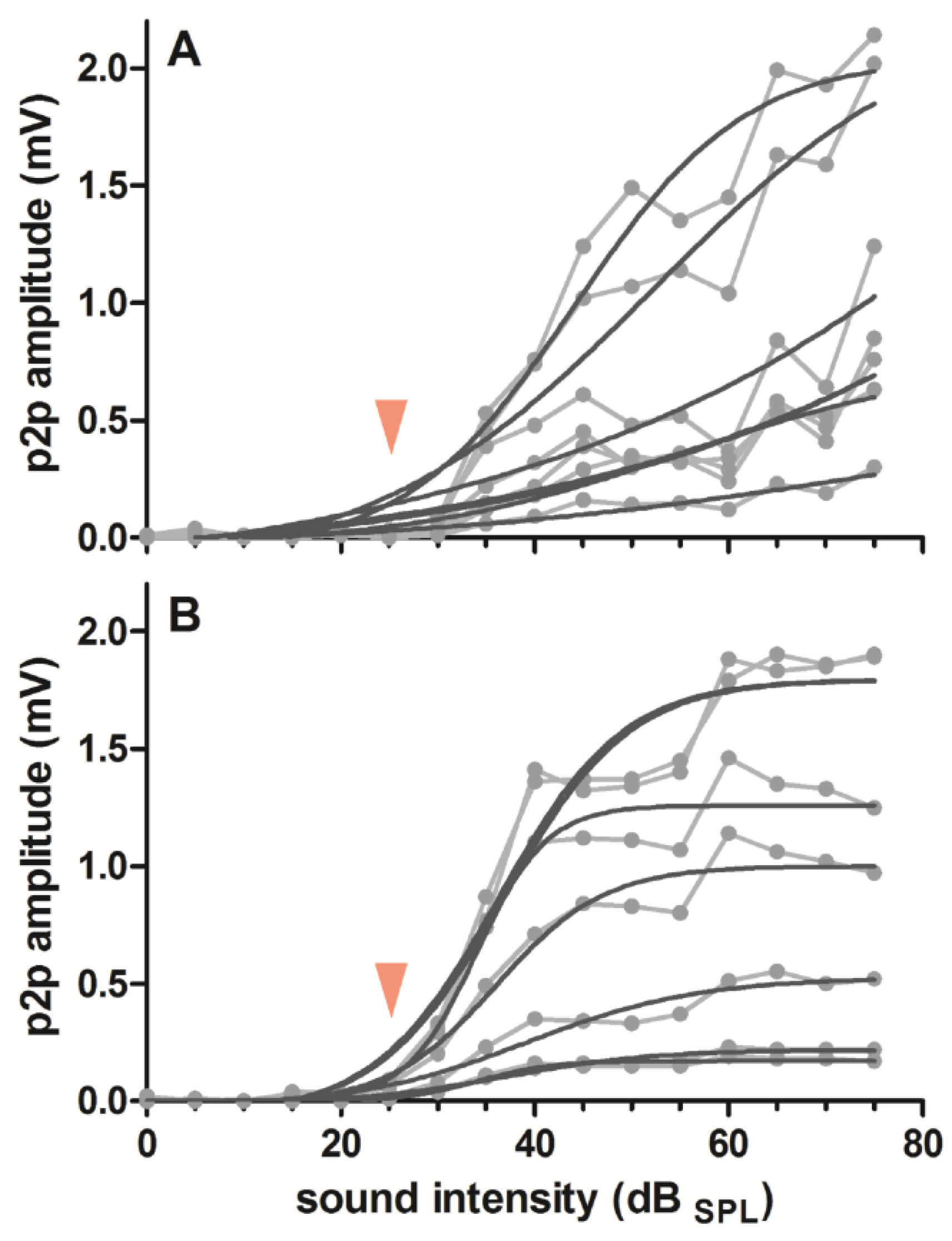
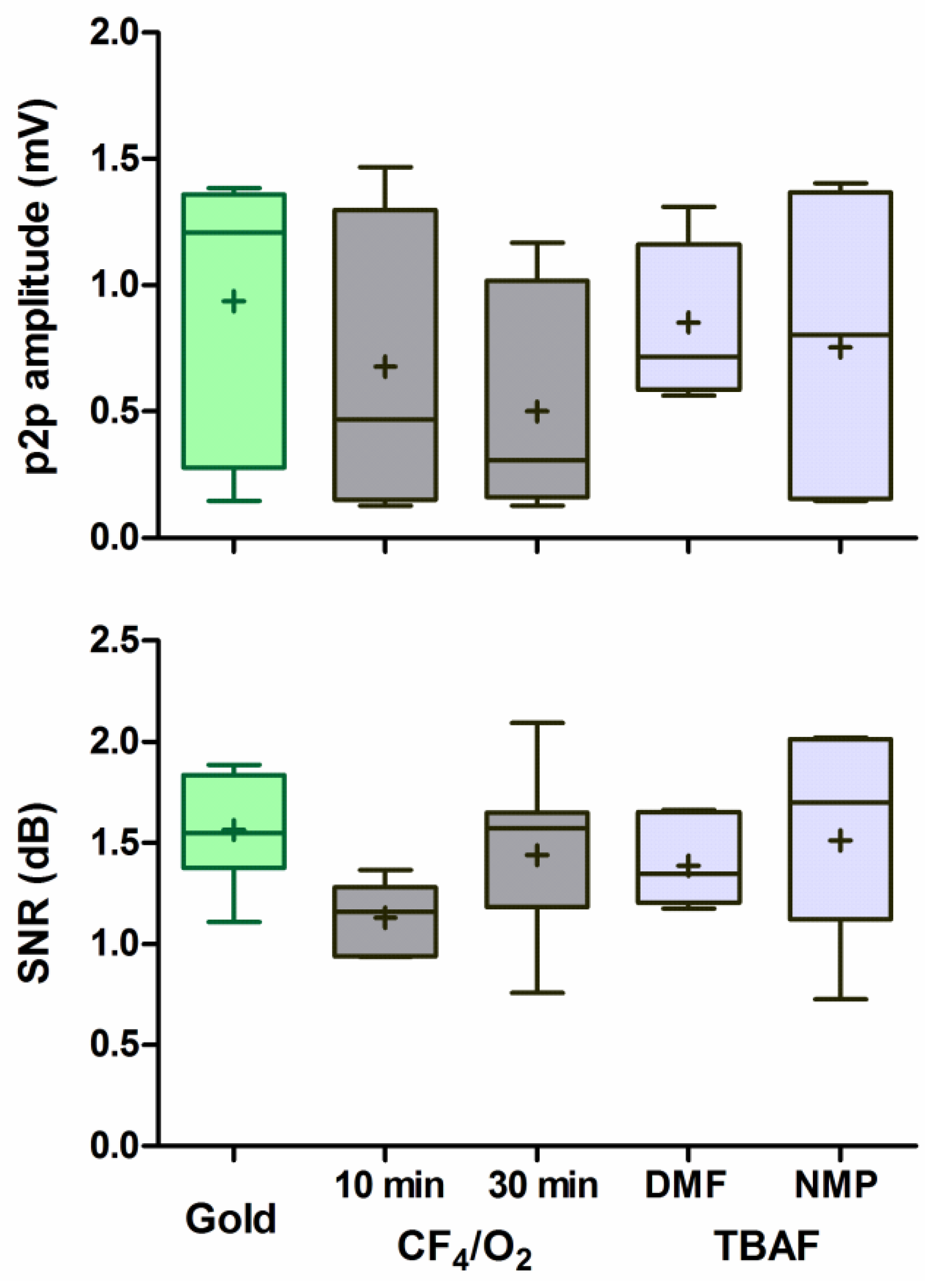
3.2. Response Amplitude and Signal-to-Noise Ratio
4. Discussion
4.1. Impedance
4.2. Response Amplitude and Signal-to-Noise Ratio
4.3. Outlook
5. Conclusions
Author Contributions
Funding
Data Availability Statement
Acknowledgments
Conflicts of Interest
References
- Kral, A.; Yusuf, P.A.; Land, R. Higher-order auditory areas in congenital deafness: Top-down interactions and corticocortical decoupling. Hear. Res. 2017, 343, 50–63. [Google Scholar] [CrossRef] [PubMed]
- Tóth, E.; Fabó, D.; Entz, L.; Ulbert, I.; Erőss, L. Intracranial neuronal ensemble recordings and analysis in epilepsy. J. Neurosci. Methods 2016, 260, 261–269. [Google Scholar] [CrossRef]
- Konerding, W.S.; Janssen, H.; Hubka, P.; Tornøe, J.; Mistrik, P.; Wahlberg, L.; Lenarz, T.; Kral, A.; Scheper, V. Encapsulated cell device approach for combined electrical stimulation and neurotrophic treatment of the deaf cochlea. Hear. Res. 2017, 350, 110–121. [Google Scholar] [CrossRef] [PubMed]
- Bareket-Keren, L.; Hanein, Y. Carbon nanotube-based multi electrode arrays for neuronal interfacing: Progress and prospects. Front. Neural Circuits 2013, 6, 1–16. [Google Scholar] [CrossRef]
- Keefer, E.W.; Botterman, B.R.; Romero, M.I.; Rossi, A.F.; Gross, G.W. Carbon nanotube coating improves neuronal recordings. Nat. Nanotechnol. 2008, 3, 434. [Google Scholar] [CrossRef] [PubMed]
- Angelov, S.D.; Koenen, S.; Jakobi, J.; Heissler, H.E.; Alam, M.; Schwabe, K.; Barcikowski, S.; Krauss, J.K. Electrophoretic deposition of ligand-free platinum nanoparticles on neural electrodes affects their impedance in vitro and in vivo with no negative effect on reactive gliosis. J. Nanobiotechnology 2016, 14, 3. [Google Scholar] [CrossRef]
- Yamagiwa, S.; Fujishiro, A.; Sawahata, H.; Numano, R.; Ishida, M.; Kawano, T. Layer-by-layer assembled nanorough iridium-oxide/platinum-black for low-voltage microscale electrode neurostimulation. Sensors Actuators B Chem. 2015, 206, 205–211. [Google Scholar] [CrossRef]
- Ludwig, K.A.; Uram, J.D.; Yang, J.; Martin, D.C.; Kipke, D.R. Chronic neural recordings using silicon microelectrode arrays electrochemically deposited with a poly(3,4-ethylenedioxythiophene) (PEDOT) Film. J. Neural Eng. 2006, 3, 59–70. [Google Scholar] [CrossRef] [PubMed]
- Wang, K.; Fishman, H.A.; Dai, H.; Harris, J.S. Neural stimulation with a carbon nanotube microelectrode array. Nano Lett. 2006, 6, 2043–2048. [Google Scholar] [CrossRef] [PubMed]
- Gabay, T.; Ben-David, M.; Kalifa, I.; Sorkin, R.; Ze’ev, R.A.; Ben-Jacob, E.; Hanein, Y.; Abrams, Z.R.; Ben-Jacob, E.; Hanein, Y. Electro-chemical and biological properties of carbon nanotube based multi-electrode arrays. Nanotechnology 2007, 18, 35201. [Google Scholar] [CrossRef] [PubMed]
- Mazzatenta, A.; Giugliano, M.; Campidelli, S.; Gambazzi, L.; Businaro, L.; Markram, H.; Prato, M.; Ballerini, L. Interfacing neurons with carbon nanotubes: Electrical signal transfer and synaptic stimulation in cultured brain circuits. J. Neurosci. 2007, 27, 6931–6936. [Google Scholar] [CrossRef]
- Liu, T.-C.; Chuang, M.-C.; Chu, C.-Y.; Huang, W.-C.; Lai, H.-Y.; Wang, C.-T.; Chu, W.-L.; Chen, S.-Y.; Chen, Y.-Y. Implantable graphene-based neural electrode interfaces for electrophysiology and neurochemistry in in vivo hyperacute stroke model. ACS Appl. Mater. Interfaces 2016, 8, 187–196. [Google Scholar] [CrossRef]
- Jorfi, M.; Skousen, J.L.; Weder, C.; Capadona, J.R. Progress towards biocompatible intracortical microelectrodes for neural interfacing applications. J. Neural Eng. 2015, 12, 011001. [Google Scholar] [CrossRef]
- Matsuoka, M.; Akasaka, T.; Hashimoto, T.; Totsuka, Y.; Watari, F. Improvement in cell proliferation on silicone rubber by carbon nanotube coating. Biomed. Mater. Eng. 2009, 19, 155–162. [Google Scholar] [CrossRef] [PubMed]
- Matsuoka, M.; Akasaka, T.; Totsuka, Y.; Watari, F. Strong adhesion of saos-2 cells to multi-walled carbon nanotubes. Mater. Sci. Eng. B 2010, 173, 182–186. [Google Scholar] [CrossRef][Green Version]
- Mattson, M.P.; Haddon, R.C.; Rao, A.M. Molecular functionalization of carbon nanotubes and use as substrates for neuronal growth. J. Mol. Neurosci. 2000, 14, 175–182. [Google Scholar] [CrossRef]
- Shin, J.H.; Kim, G.B.; Lee, E.J.; An, T.; Shin, K.; Lee, S.E.; Choi, W.; Lee, S.; Latchoumane, C.; Shin, H.-S.; et al. Carbon-nanotube-modified electrodes for highly efficient acute neural recording. Adv. Healthc. Mater. 2014, 3, 245–252. [Google Scholar] [CrossRef]
- Castagnola, E.; Ansaldo, A.; Fadiga, L.; Ricci, D. Chemical vapour deposited carbon nanotube coated microelectrodes for intracortical neural recording. Phys. Status Solidi 2010, 247, 2703–2707. [Google Scholar] [CrossRef]
- Lin, C.-M.M.; Lee, Y.-T.T.; Yeh, S.-R.R.; Fang, W. Flexible carbon nanotubes electrode for neural recording. Biosens. Bioelectron. 2009, 24, 2791–2797. [Google Scholar] [CrossRef]
- Jung, H.C.; Moon, J.H.; Baek, D.H.; Lee, J.H.; Choi, Y.Y.; Hong, J.S.; Lee, S.H.; Jung, H.; Moon, J.; Baek, D.-H.; et al. CNT/PDMS Composite Flexible Dry Electrodesfor Long-Term ECG Monitoring. IEEE Trans. Biomed. Eng. 2012, 59, 1472–1479. [Google Scholar] [CrossRef]
- David-Pur, M.; Bareket-Keren, L.; Beit-Yaakov, G.; Raz-Prag, D.; Hanein, Y. All-carbon-nanotube flexible multi-electrode array for neuronal recording and stimulation. Biomed. Microdevices 2014, 16, 43–53. [Google Scholar] [CrossRef]
- Burblies, N.; Schulze, J.; Schwarz, H.-C.C.; Kranz, K.; Motz, D.; Vogt, C.; Lenarz, T.; Warnecke, A.; Behrens, P. Coatings of different carbon nanotubes on platinum electrodes for neuronal devices: Preparation, cytocompatibility and interaction with spiral ganglion cells. PLoS ONE 2016, 11, e0158571. [Google Scholar] [CrossRef] [PubMed]
- Rittinghausen, S.; Hackbarth, A.; Creutzenberg, O.; Ernst, H.; Heinrich, U.; Leonhardt, A.; Schaudien, D. The carcinogenic effect of various multi-walled carbon nanotubes (MWCNTs) after intraperitoneal injection in rats. Part. Fibre Toxicol. 2014, 11, 59. [Google Scholar] [CrossRef]
- Tegtmeier, K.; Aliuos, P.; Lenarz, T.; Doll, T. Residual rubber shielded multi walled carbon nanotube electrodes for neural interfacing in active medical implants. Phys. Med. 2016, 1, 8–19. [Google Scholar] [CrossRef]
- Behrens, A.; Foremny, K.; Doll, T. Carbon nanotube-silicone rubber on active thin-film implants. Phys. Status Solidi 2018, 215, 1700873. [Google Scholar] [CrossRef]
- Tegtmeier, K.; Borrmann, F.; Doll, T. Wet-etch induced changes in impedance of carbon nanotube-silicone rubber electrode materials for active implants. Procedia Eng. 2016, 168, 1168–1171. [Google Scholar] [CrossRef]
- Konerding, W.S.; Froriep, U.P.; Kral, A.; Baumhoff, P. New thin-film surface electrode array enables brain mapping with high spatial acuity in rodents. Sci. Rep. 2018, 8, 3825. [Google Scholar] [CrossRef] [PubMed]
- Rodger, D.C.; Fong, A.J.; Li, W.; Ameri, H.; Ahuja, A.K.; Gutierrez, C.; Lavrov, I.; Zhong, H.; Menon, P.R.; Meng, E.; et al. Flexible parylene-based multielectrode array technology for high-density neural stimulation and recording. Sens. Actuators B Chem. 2008, 132, 449–460. [Google Scholar] [CrossRef]
- Sato, M.; Baumhoff, P.; Kral, A. Cochlear implant stimulation of a hearing ear generates separate electrophonic and electroneural responses. J. Neurosci. 2016, 36, 54–64. [Google Scholar] [CrossRef]
- Li, C.; Thostenson, E.T.; Chou, T.-W. Dominant role of tunneling resistance in the electrical conductivity of carbon nanotube–based composites. Appl. Phys. Lett. 2007, 91, 223114. [Google Scholar] [CrossRef]
- Beigbeder, A.; Linares, M.; Devalckenaere, M.; Degée, P.; Claes, M.; Beljonne, D.; Lazzaroni, R.; Dubois, P. CH-π interactions as the driving force for silicone-based nanocomposites with exceptional properties. Adv. Mater. 2008, 20, 1003–1007. [Google Scholar] [CrossRef]
- Nelson, M.J.; Pouget, P. Do Electrode properties create a problem in interpreting local field potential recordings? J. Neurophysiol. 2010, 103, 2315–2317. [Google Scholar] [CrossRef] [PubMed]
- Hsu, H.-L.; Teng, I.-J.; Chen, Y.-C.; Hsu, W.-L.; Lee, Y.-T.; Yen, S.-J.; Su, H.-C.; Yeh, S.-R.; Chen, H.; Yew, T.-R. Flexible UV-ozone-modified carbon nanotube electrodes for neuronal recording. Adv. Mater. 2010, 22, 2177–2181. [Google Scholar] [CrossRef] [PubMed]


Publisher’s Note: MDPI stays neutral with regard to jurisdictional claims in published maps and institutional affiliations. |
© 2021 by the authors. Licensee MDPI, Basel, Switzerland. This article is an open access article distributed under the terms and conditions of the Creative Commons Attribution (CC BY) license (https://creativecommons.org/licenses/by/4.0/).
Share and Cite
Foremny, K.; Konerding, W.S.; Behrens, A.; Baumhoff, P.; Froriep, U.P.; Kral, A.; Doll, T. Carbon-Nanotube-Coated Surface Electrodes for Cortical Recordings In Vivo. Nanomaterials 2021, 11, 1029. https://doi.org/10.3390/nano11041029
Foremny K, Konerding WS, Behrens A, Baumhoff P, Froriep UP, Kral A, Doll T. Carbon-Nanotube-Coated Surface Electrodes for Cortical Recordings In Vivo. Nanomaterials. 2021; 11(4):1029. https://doi.org/10.3390/nano11041029
Chicago/Turabian StyleForemny, Katharina, Wiebke S. Konerding, Ailke Behrens, Peter Baumhoff, Ulrich P. Froriep, Andrej Kral, and Theodor Doll. 2021. "Carbon-Nanotube-Coated Surface Electrodes for Cortical Recordings In Vivo" Nanomaterials 11, no. 4: 1029. https://doi.org/10.3390/nano11041029
APA StyleForemny, K., Konerding, W. S., Behrens, A., Baumhoff, P., Froriep, U. P., Kral, A., & Doll, T. (2021). Carbon-Nanotube-Coated Surface Electrodes for Cortical Recordings In Vivo. Nanomaterials, 11(4), 1029. https://doi.org/10.3390/nano11041029