
Contribution to Improvement of Fatigue Properties of Zr-4 Alloy: Gradient Nanostructured Surface Layer versus Compressive Residual Stress


Abstract
:1. Introduction
2. Materials and Methods
3. Results
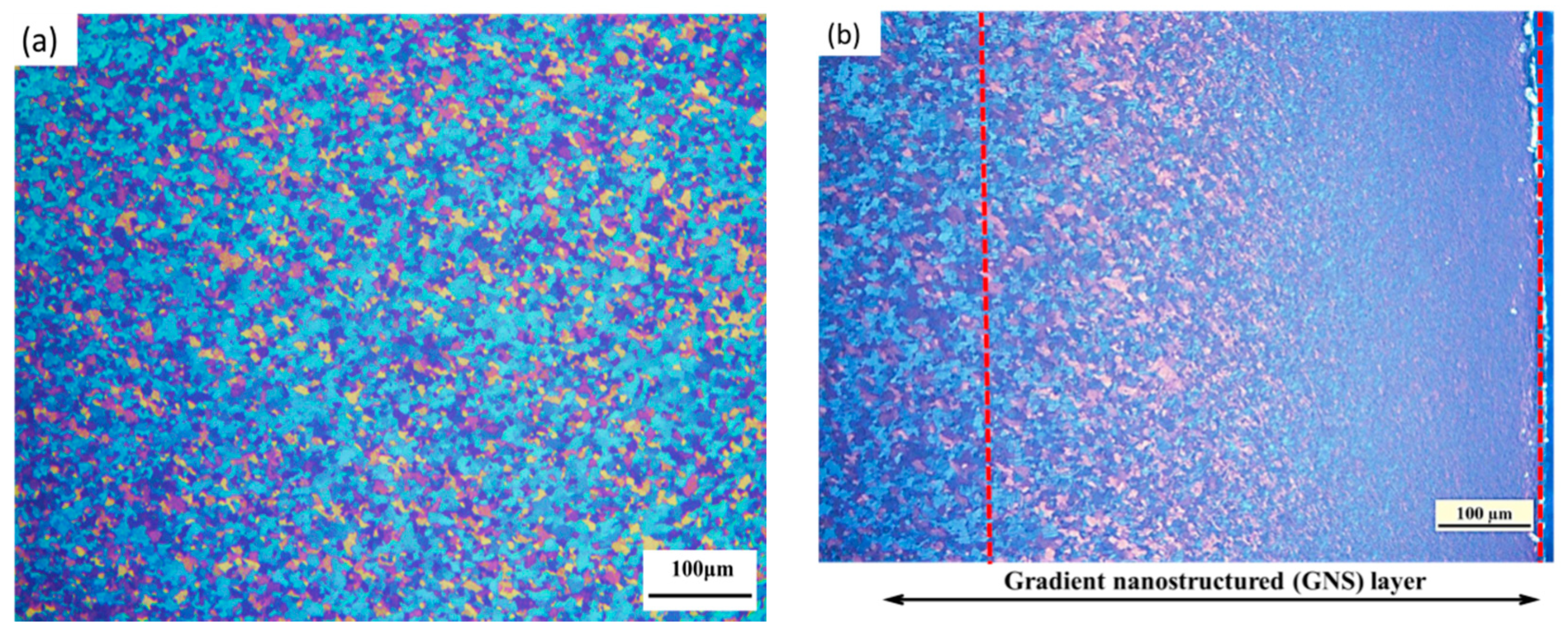
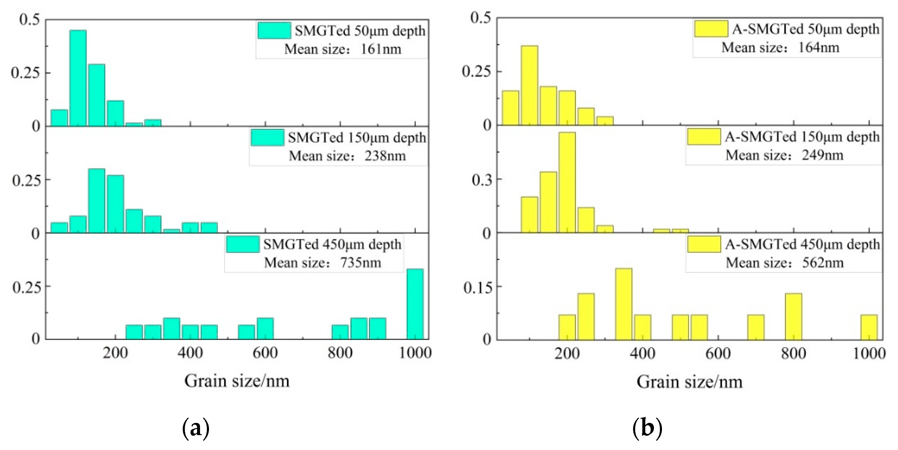
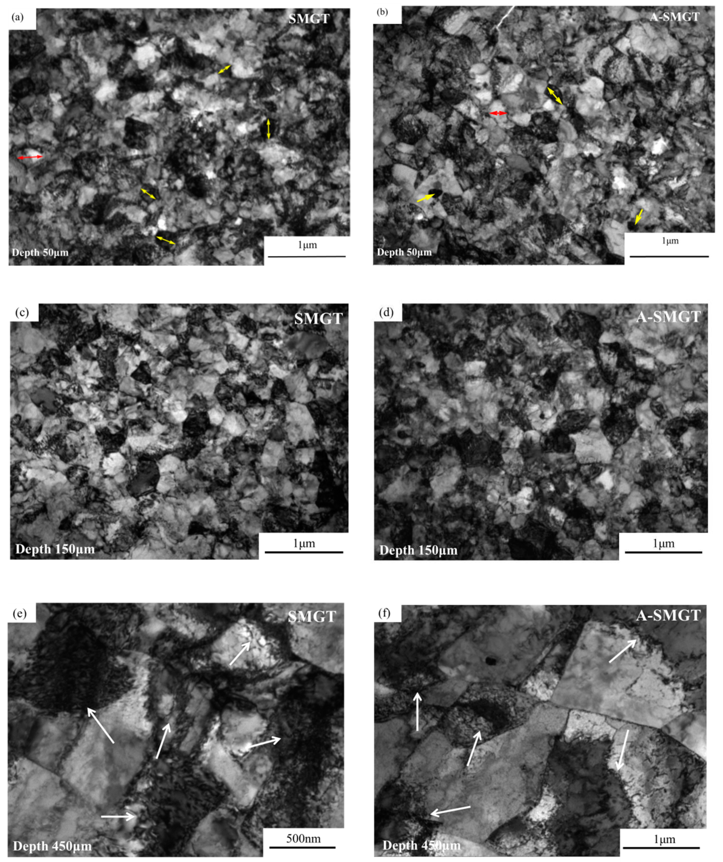
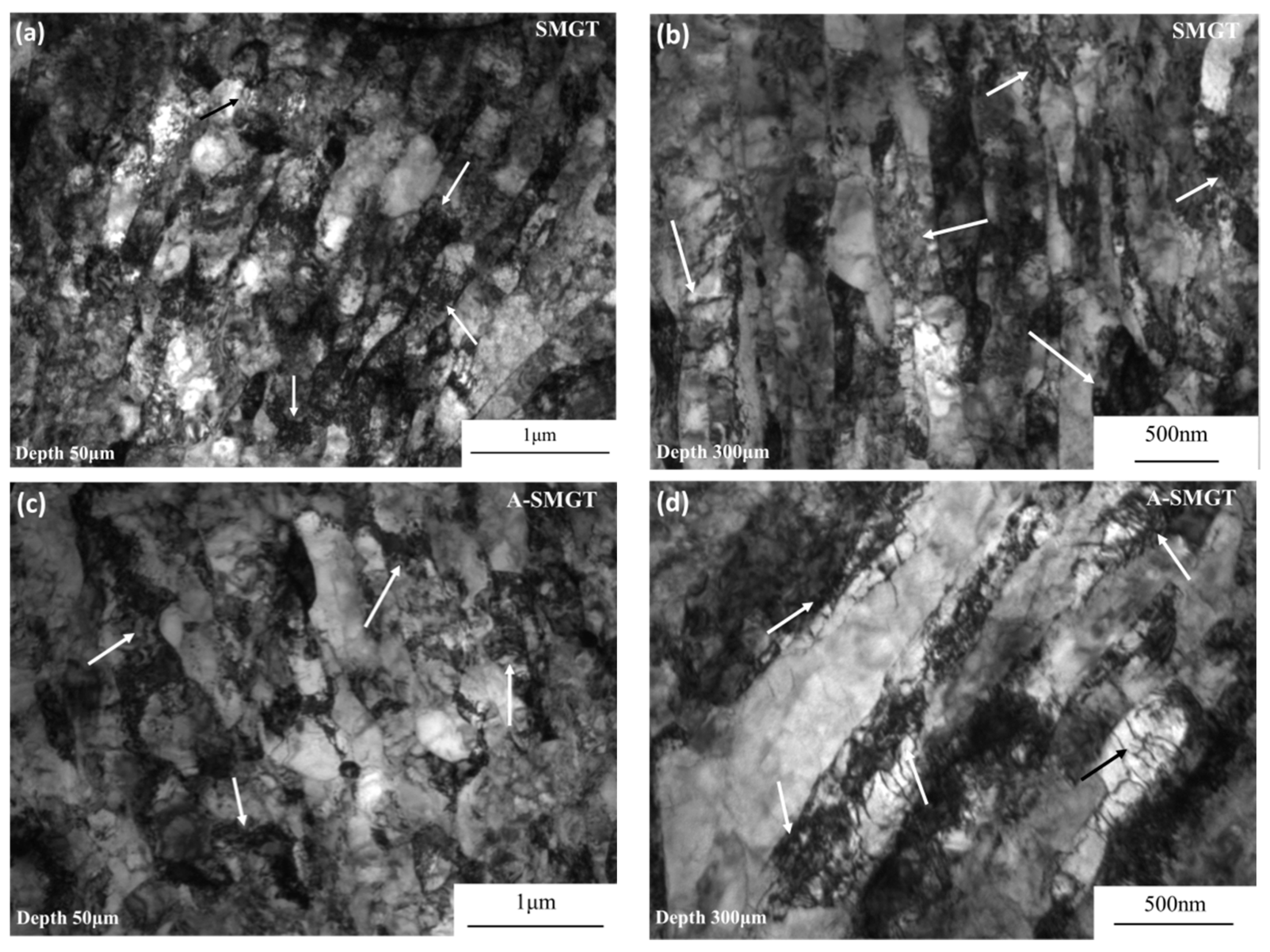
3.1. Microstructure
3.2. Compressive Residual Stress
3.3. Fatigue Behaviors
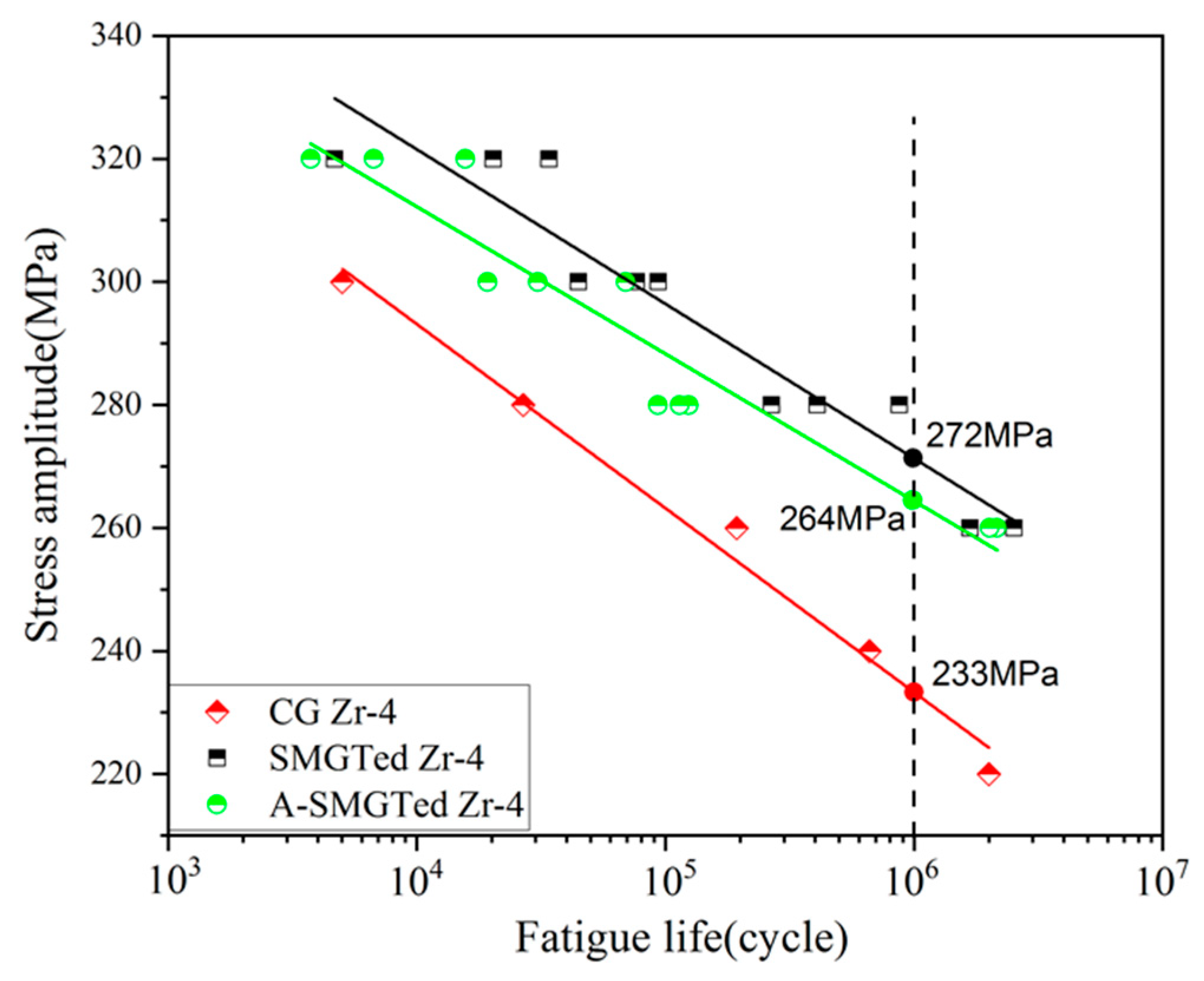
3.3.1. S-N Curve
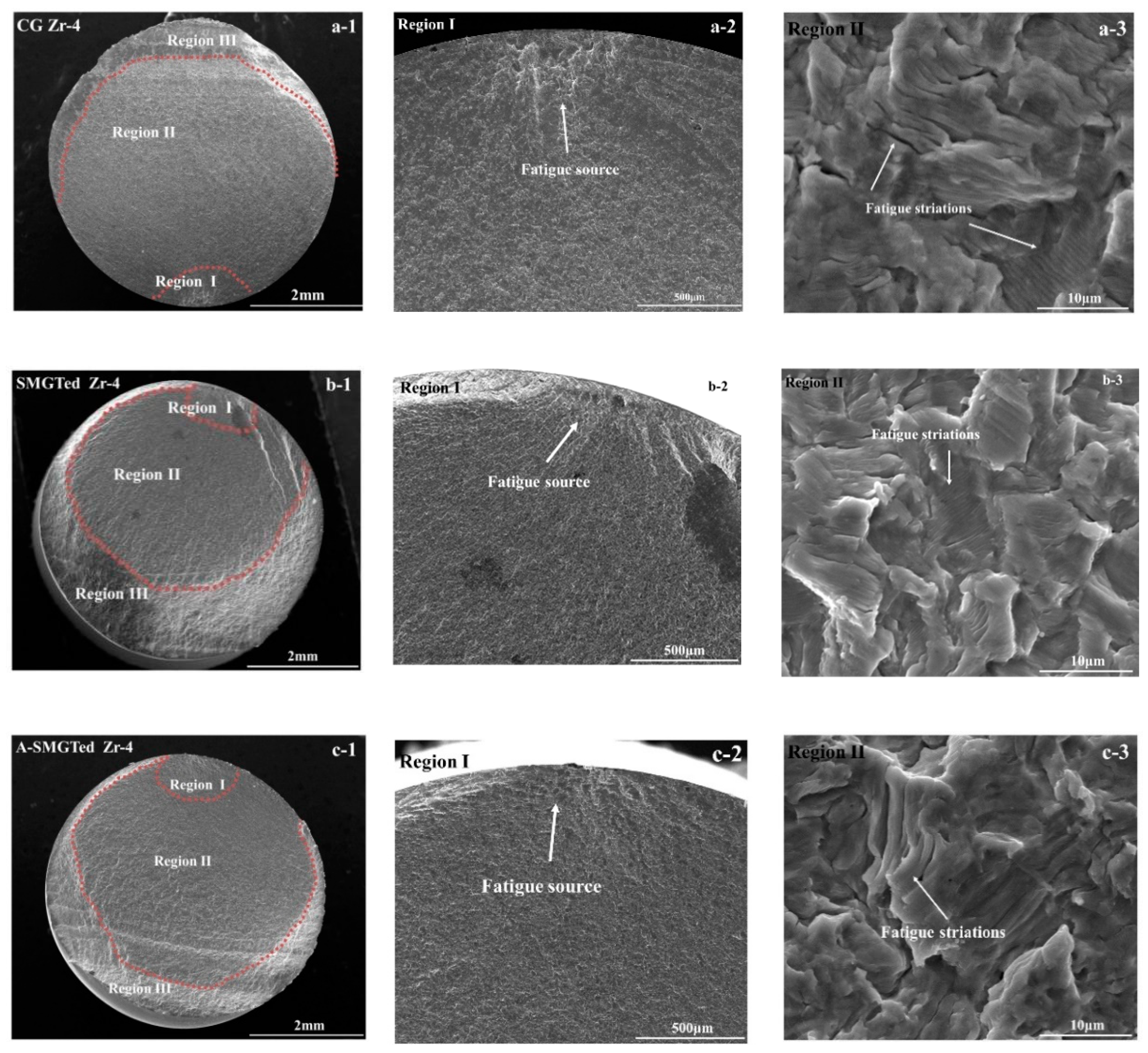
3.3.2. Fatigue Fracture
4. Discussion
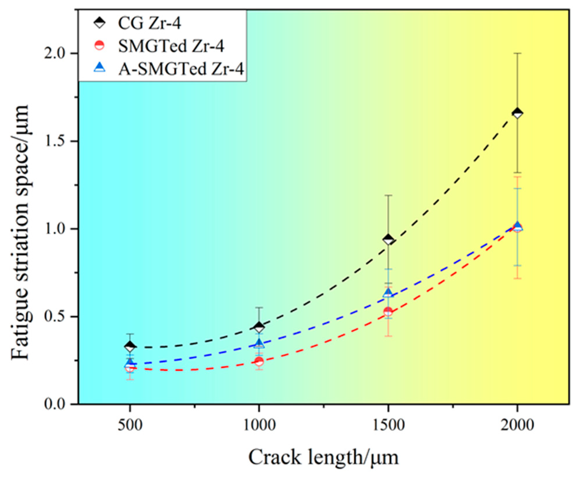
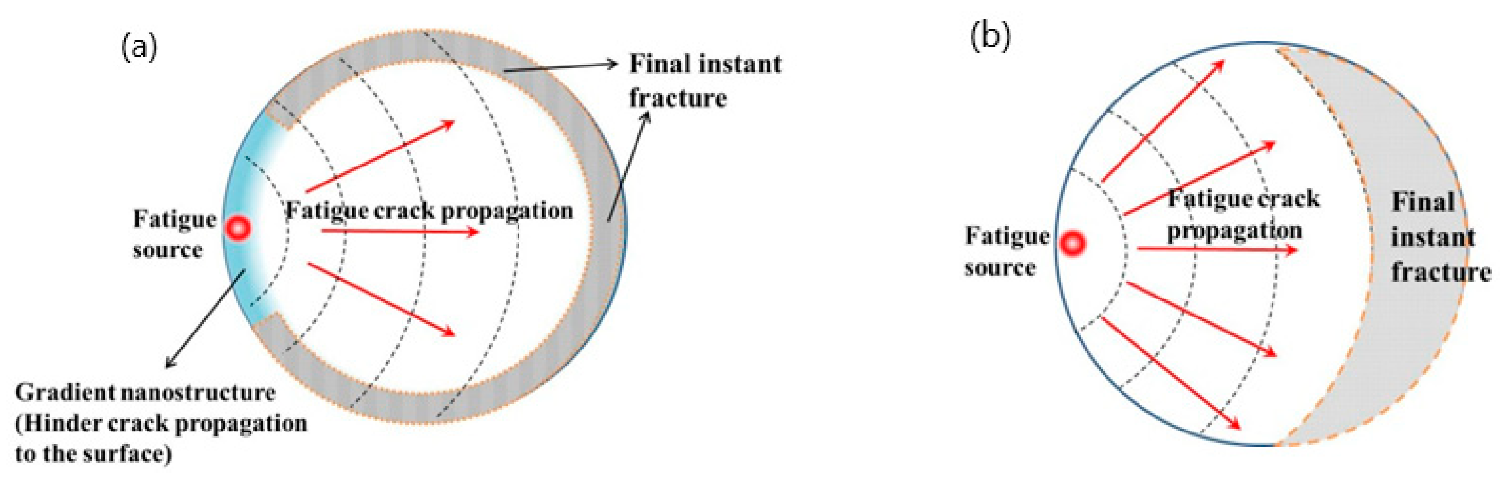
4.1. Fatigue Crack Propagation Behavior
4.2. Enhancement Mechanisms of Fatigue Performance of Zr-4 Alloy with GNS Surface Layer
5. Conclusions
- (1)
- The gradient nanostructured surface layer in the Zr-4 samples by the SMGT process is stable after annealing at 400 °C for 2h, while the compressive residual stress is apparently relaxed.
- (2)
- The fatigue strengths of the SMGTed and A-SMGTed Zr-4 samples are much higher than that of the CG Zr-4 samples. The fatigue limits of the A-SMGTed Zr-4 samples decrease a little when compared to that of the SMGTed Zr-4 alloy, but are much higher than that of the CG Zr-4 alloy. This means that the GNS layer affects the fatigue limit more than the residual compressive stress for the Zr-4 alloy.
- (3)
- The surface gradient nanostructured layer is a key factor for improvement in the tensile–compressive fatigue properties of the SMGTed Zr-4 alloy by delaying crack initiation and decreasing the crack propagation rate.
Author Contributions
Funding
Data Availability Statement
Conflicts of Interest
References
- Fang, T.H.; Li, W.L.; Tao, N.R.; Lu, K. Revealing Extraordinary Intrinsic Tensile Plasticity in Gradient Nano-Grained Copper. Science 2011, 331, 1587–1590. [Google Scholar] [CrossRef] [Green Version]
- Wu, X.; Jiang, P.; Chen, L.; Zhu, Y.T. Extraordinary strain hardening by gradient structure. Proc. Natl. Acad. Sci. USA 2014, 111, 7197–7201. [Google Scholar] [CrossRef] [Green Version]
- Lu, K. Nanostructured surface layer on metallic materials induced by surface mechanical attrition treatment. Mater. Sci. Eng. A 2004, 75, 38–45. [Google Scholar] [CrossRef]
- Yin, Y.F.; Xu, W.; Sun, Q.Y.; Sun, J. Deformation and fracture behavior of commercially pure titanium with gradient nano-to-micron-grained surface layer. Trans. Nonferrous Met. Soc. China 2015, 25, 738–747. [Google Scholar] [CrossRef]
- Cheng, Q.; Fang, T.H.; Xie, P.; Xu, X.D. Impact of surface gradient structures on mechanical properties of a dual-phase AlCrFe2(Ni0.85Co0.15)2 multi-component eutectic alloy. J. Alloy. Compd. 2021, 882, 160591. [Google Scholar] [CrossRef]
- Wu, X.L.; Jiang, P.; Chen, L.; Zhang, J.F.; Yuan, F.P.; Zhu, Y.T. Synergetic Strengthening by Gradient Structure. Mater. Res. Lett. 2014, 2, 185–191. [Google Scholar] [CrossRef]
- Wei, W.; Wei, K.X.; Fan, G.J. A new constitutive equation for strain hardening and softening of fcc metals during severe plastic deformation. Acta Mater. 2008, 56, 4771–4779. [Google Scholar] [CrossRef]
- Feng, T.; Schoenung, J.M. Strain softening in nanocrystalline or ultrafine-grained metals: A mechanistic explanation. Mater. Sci. Eng. A 2008, 493, 101–103. [Google Scholar]
- Lei, Y.B.; Wang, Z.B.; Xu, J.L.; Lu, K. Simultaneous enhancement of stress- and strain-controlled fatigue properties in 316L stainless steel with gradient nanostructure. Acta Mater. 2019, 168, 133–142. [Google Scholar] [CrossRef]
- Wang, Q.; Xiao, L.; Sun, J.; Sun, Q.Y. Torsion fatigue behavior of pure titanium with a gradient nanostructured surface layer. Mater. Sci. Eng. A Struct. Mater. Prop. Misrostruct. Process. 2016, 649, 359–368. [Google Scholar] [CrossRef]
- Wang, Q.; Sun, Q.Y.; Xiao, L.; Sun, J. Effect of Surface Nanocrystallization on Fatigue Behavior of Pure Titanium. J. Mater. Eng. Perform. 2016, 25, 241–249. [Google Scholar] [CrossRef]
- Huang, H.W.; Wang, Z.B.; Lu, J.; Lu, K. Fatigue behaviors of AISI 316L stainless steel with a gradient nanostructured surface layer. Acta Mater. 2015, 87, 150–160. [Google Scholar] [CrossRef]
- Liu, C.S.; Liu, D.X.; Zhang, X.H.; Liu, D.; Ma, A.M.; Ao, N.; Xu, X.C. Improving fatigue performance of Ti-6Al-4V alloy via ultrasonic surface rolling process. J. Mater. Sci. Technol. 2019, 35, 1555–1562. [Google Scholar] [CrossRef]
- Fuketa, T.; Sasajima, H.; Sugiyama, T. Behavior of High-Burnup PWR Fuels with Low-Tin Zircaloy-4 Cladding Under Reactivity-Initiated-Accident Conditions. Nucl. Technol. 2001, 133, 50–62. [Google Scholar] [CrossRef]
- Wang, F.; Wang, K.; Linsheng, M.A.; Zhang, B.; Kong, L.; Lin, Z. Current situation and development trend of zirconium and zirconium alloys. Ordnance Mater. Sci. Eng. 2012, 1, 138284414. [Google Scholar]
- Tong, V.S.; Britton, T.B. Formation of very large ‘blocky alpha’ grains in Zircaloy-4. Acta Mater. 2017, 129, 510–520. [Google Scholar] [CrossRef]
- Zhang, C.; Song, G.; Xin, Y.; Zhu, W.; Zeng, X. Microstructure characterization of gradient structured surface layer in pure zirconium. Mater. Charact. 2021, 173, 110924. [Google Scholar] [CrossRef]
- Xiao, L.; Umakoshi, Y.; Sun, J. Biaxial low cycle fatigue properties and dislocation substructures of zircaloy-4 under in-phase and out-of-phase loading. Mater. Sci. Eng. A 2000, 292, 40–48. [Google Scholar] [CrossRef]
- Han, F.Z.; Liu, C.Z.; Yuan, F.S.; Zhang, Y.D.; Ali, M.; Gu, H.F.; Li, G.P. Microscopic characterization on low cycle fatigue behavior at room temperature of Zircaloy-4 alloy with recrystallized microstructure. J. Alloy. Compd. 2018, 778, 318–326. [Google Scholar] [CrossRef]
- Armas, A.F.; Hereñú, S.; Bolmaro, R.; Alvarez-Armas, I. Cyclic softening mechanisms of Zircaloy-4. J. Nucl. Mater. 2004, 326, 195–200. [Google Scholar] [CrossRef]
- Nikulin, S.A.; Rozhnov, A.B.; Gusev, A.Y.; Nechaykina, T.A.; Zadorozhnyy, M.Y. Fracture resistance of Zr–Nb alloys under low-cycle fatigue tests. J. Nucl. Mater. 2014, 446, 10–14. [Google Scholar] [CrossRef]
- Sun, Z.; Retraint, D.; Baudin, T.; Helbert, A.L.; Brisset, F.; Chemkhi, M.; Zhou, J.; Kanouté, P. Experimental study of microstructure changes due to low cycle fatigue of a steel nanocrystallised by Surface Mechanical Attrition Treatment (SMAT). Mater. Charact. 2017, 124, 117–121. [Google Scholar] [CrossRef]
- Chen, G.; Gao, J.W.; Cui, Y.; Gao, H.; Guo, X.; Wu, S.Z. Effects of strain rate on the low cycle fatigue behavior of AZ31B magnesium alloy processed by SMAT. J. Alloy. Compd. 2018, 735, 536–546. [Google Scholar] [CrossRef]
- Roland, T.; Retraint, D.; Lu, K.; Lu, J. Fatigue life improvement through surface nanostructuring of stainless steel by means of surface mechanical attrition treatment. Scr. Mater. 2006, 54, 1949–1954. [Google Scholar] [CrossRef]
- Li, D.; Chen, H.N.; Xu, H. The effect of nanostructured surface layer on the fatigue behaviors of a carbon steel. Appl. Surf. Sci. 2009, 255, 3811–3816. [Google Scholar] [CrossRef]
- Zhang, C.H.; Song, G.D.; Wang, Y.M.; Zheng, M.; Xiao, G.Z.; Yang, J. Effect of surface nanocrystallization on fatigue crack initiation and propagation behavior in pure Zr. Mater. Sci. Eng. A 2020, 794, 139831. [Google Scholar] [CrossRef]
- Zhang, C.H.; Zeng, X.K.; Cheng, J.P.; Wang, Y.M. Fatigue life improvement and grain growth of gradient nanostructured industrial zirconium during high cycle fatigue. J. Mater. Sci. Technol. 2021, 87, 101–107. [Google Scholar] [CrossRef]
- Xin, C.; Sun, Q.Y.; Xiao, L.; Sun, J. Biaxial fatigue property enhancement of gradient ultra-fine-grained Zircaloy-4 prepared by surface mechanical rolling treatment. J. Mater. Sci. 2018, 53, 12492–12503. [Google Scholar] [CrossRef]
- Xin, C.; Yang, D.; Sun, Q.Y.; Xiao, L.; Sun, J. Thermal stability of nanogradient microstructure produced by surface mechanical rolling treatment in Zircaloy-4. J. Mater. Sci. 2020, 55, 4926–4939. [Google Scholar] [CrossRef]
- Wang, Q.; Yin, Y.F.; Sun, Q.Y.; Xiao, L.; Sun, J. Gradient nano microstructure and its formation mechanism in pure titanium produced by surface rolling treatment. J. Mater. Res. 2014, 29, 569–577. [Google Scholar] [CrossRef]
- Li, R.H.; Zhang, Z.J.; Zhang, P.; Zhang, Z.F. Improved fatigue properties of ultrafine-grained copper under cyclic torsion loading. Acta Mater. 2013, 61, 5857–5868. [Google Scholar] [CrossRef]
- Shyam, A.; Lara-Curzio, E. A model for the formation of fatigue striations and its relationship with small fatigue crack growth in an aluminum alloy. Int. J. Fatigue 2010, 32, 1843–1852. [Google Scholar] [CrossRef]
- Bulloch, J.H.; Callagy, A.G. A detailed study of the relationship between fatigue crack growth rate and striation spacing in a range of low alloy ferritic steels. Eng. Fail. Anal. 2010, 17, 168–178. [Google Scholar] [CrossRef]
- Williams, J.J.; Yazzie, K.E.; Phillips, N.C.; Chawla, N.; Xiao, X.; Carlo, F.D.; Iyyer, N.; Kittur, M. On the Correlation between Fatigue Striation Spacing and Crack Growth Rate: A Three-Dimensional (3-D) X-ray Synchrotron Tomography Study. Metall. Mater. Trans. A 2011, 42, 3845–3848. [Google Scholar] [CrossRef]
- Xin, C.; Sun, Q.Y.; Xiao, L.; Sun, J. Synergetic Strengthening of Grain Refinement and Texture in Gradient Zircaloy-4 by Surface Mechanical Rolling Treatment. J. Mater. Eng. Perform. 2019, 28, 6354–6364. [Google Scholar] [CrossRef]


| Elements | Sn | Fe | Cr | Hf | Al | Ti | Co | C | H | O | N | Zr |
|---|---|---|---|---|---|---|---|---|---|---|---|---|
| Content | 1.4 | 0.21 | 0.09 | <0.01 | 0.0015 | <0.002 | <0.001 | 0.005 | 0.001 | 0.095 | 0.003 | Bal. |
| CG | SMGTed | A-SMGTed |
|---|---|---|
| σ𝑎 = 438(2Nf)−0.045 | σ𝑎 = 455(2Nf)−0.037 | σ𝑎 = 455(2Nf)−0.040 |
Publisher’s Note: MDPI stays neutral with regard to jurisdictional claims in published maps and institutional affiliations. |
© 2021 by the authors. Licensee MDPI, Basel, Switzerland. This article is an open access article distributed under the terms and conditions of the Creative Commons Attribution (CC BY) license (https://creativecommons.org/licenses/by/4.0/).
Share and Cite
Geng, D.; Sun, Q.; Xin, C.; Xiao, L. Contribution to Improvement of Fatigue Properties of Zr-4 Alloy: Gradient Nanostructured Surface Layer versus Compressive Residual Stress. Nanomaterials 2021, 11, 3125. https://doi.org/10.3390/nano11113125
Geng D, Sun Q, Xin C, Xiao L. Contribution to Improvement of Fatigue Properties of Zr-4 Alloy: Gradient Nanostructured Surface Layer versus Compressive Residual Stress. Nanomaterials. 2021; 11(11):3125. https://doi.org/10.3390/nano11113125
Chicago/Turabian StyleGeng, Donghui, Qiaoyan Sun, Chao Xin, and Lin Xiao. 2021. "Contribution to Improvement of Fatigue Properties of Zr-4 Alloy: Gradient Nanostructured Surface Layer versus Compressive Residual Stress" Nanomaterials 11, no. 11: 3125. https://doi.org/10.3390/nano11113125
APA StyleGeng, D., Sun, Q., Xin, C., & Xiao, L. (2021). Contribution to Improvement of Fatigue Properties of Zr-4 Alloy: Gradient Nanostructured Surface Layer versus Compressive Residual Stress. Nanomaterials, 11(11), 3125. https://doi.org/10.3390/nano11113125