
Thermal Radiative Copper Oxide Layer for Enhancing Heat Dissipation of Metal Surface


Abstract
:1. Introduction
2. Materials and Methods
3. Results and Discussion
4. Conclusions
Author Contributions
Funding
Institutional Review Board Statement
Informed Consent Statement
Data Availability Statement
Conflicts of Interest
References
- Chen, C.; Xie, X.; Yang, M.; Seok, I.; Guo, Z.; Jiang, Q.; Wangila, G.; Zhang, H.; Liu, Q. Recent Advances in Solar Energy Full Spectrum Conversion and Utilization. ES Energy Environ. 2021, 11, 3–18. [Google Scholar]
- Gao, Y.; Wang, Z.; Ding, D.; Li, W.; Ma, Y.; Hao, Y.; Zhang, H. Novel methods to harness solar radiation for advanced energy applications. ES Energy Environ. 2019, 5, 1–7. [Google Scholar] [CrossRef]
- Shaikh, A.V.; Sayyed, S.G.; Naeem, S.; Mane, R.S. Electrodeposition of n-CdSe/p-Cu2Se heterojunction solar cells. Eng. Sci. 2020, 13, 79–86. [Google Scholar]
- Cheng, H.H.; Huang, D.-S.; Lin, M.-T. Heat dissipation design and analysis of high power LED array using the finite element method. Microelectron. Reliab. 2012, 52, 905–911. [Google Scholar] [CrossRef]
- Weng, C.-J. Advanced thermal enhancement and management of LED packages. Int. Commun. Heat Mass Transf. 2009, 36, 245–248. [Google Scholar] [CrossRef]
- Tan, F.; Tso, C. Cooling of mobile electronic devices using phase change materials. Appl. Therm. Eng. 2004, 24, 159–169. [Google Scholar] [CrossRef]
- Kalbasi, R. Introducing a novel heat sink comprising PCM and air-Adapted to electronic device thermal management. Int. J. Heat Mass Transf. 2021, 169, 120914. [Google Scholar] [CrossRef]
- Alshaer, W.; Nada, S.; Rady, M.; Le Bot, C.; Del Barrio, E.P. Numerical investigations of using carbon foam/PCM/Nano carbon tubes composites in thermal management of electronic equipment. Energy Convers. Manag. 2015, 89, 873–884. [Google Scholar]
- Choi, J.; Jeong, M.; Yoo, J.; Seo, M. A new CPU cooler design based on an active cooling heatsink combined with heat pipes. Appl. Therm. Eng. 2012, 44, 50–56. [Google Scholar] [CrossRef]
- Mohammed, H.; Gunnasegaran, P.; Shuaib, N. Influence of channel shape on the thermal and hydraulic performance of microchannel heat sink. Int. Commun. Heat Mass Transf. 2011, 38, 474–480. [Google Scholar] [CrossRef]
- Husain, A.; Kim, K.-Y. Shape optimization of micro-channel heat sink for micro-electronic cooling. IEEE Trans. Compon. Packag. Technol. 2008, 31, 322–330. [Google Scholar] [CrossRef]
- Mohammed, H.; Gunnasegaran, P.; Shuaib, N. Numerical simulation of heat transfer enhancement in wavy microchannel heat sink. Int. Commun. Heat Mass Transf. 2011, 38, 63–68. [Google Scholar] [CrossRef]
- Chai, L.; Xia, G.; Zhou, M.; Li, J. Numerical simulation of fluid flow and heat transfer in a microchannel heat sink with offset fan-shaped reentrant cavities in sidewall. Int. Commun. Heat Mass Transf. 2011, 38, 577–584. [Google Scholar] [CrossRef]
- Nieh, H.-M.; Teng, T.-P.; Yu, C.-C. Enhanced heat dissipation of a radiator using oxide nano-coolant. Int. J. Therm. Sci. 2014, 77, 252–261. [Google Scholar] [CrossRef]
- Ijam, A.; Saidur, R. Nanofluid as a coolant for electronic devices (cooling of electronic devices). Appl. Therm. Eng. 2012, 32, 76–82. [Google Scholar] [CrossRef]
- Williams, J.D.; Peterson, G. A Review of Thermal Property Enhancements of Low-Temperature Nano-Enhanced Phase Change Materials. Nanomaterials 2021, 11, 2578. [Google Scholar] [CrossRef]
- Di Pierro, A.; Mortazavi, B.; Fina, A. Molecular Junctions Enhancing Thermal Transport within Graphene Polymer Nanocomposite: A Molecular Dynamics Study. Nanomaterials 2021, 11, 2480. [Google Scholar] [CrossRef]
- Chung, Y.-C.; Chung, H.-H.; Lin, S.-H. Improvement of Temperature and Optical Power of an LED by Using Microfluidic Circulating System of Graphene Solution. Nanomaterials 2021, 11, 1719. [Google Scholar]
- Li, Q.; Xiao, Y.; Shi, X.; Song, S. Rapid evaporation of water on graphene/graphene-oxide: A molecular dynamics study. Nanomaterials 2017, 7, 265. [Google Scholar]
- Hafiz Muhammad Ali, A.A. Experimental investigation of n-eicosane based circular pin-fin heatsinks for passive cooling of electronic devices. Int. J. Heat Mass Transf. 2017, 112, 649–661. [Google Scholar]
- Ahmed, H.E.; Salman, B.; Kherbeet, A.S.; Ahmed, M. Optimization of thermal design of heat sinks: A review. Int. J. Heat Mass Transf. 2018, 118, 129–153. [Google Scholar]
- Kothari, R.; Sahu, S.K.; Kundalwal, S.I.; Mahalkar, P. Thermal performance of phase change material–based heat sink for passive cooling of electronic components: An experimental study. Int. J. Energy Res. 2021, 45, 5939–5963. [Google Scholar]
- Kim, D.; Sung, D.; Lee, J.; Kim, Y.; Chung, W. Composite plasma electrolytic oxidation to improve the thermal radiation performance and corrosion resistance on an Al substrate. Appl. Surf. Sci. 2015, 357, 1396–1402. [Google Scholar] [CrossRef]
- Kim, D.; Lee, J.; Kim, J.; Choi, C.-H.; Chung, W. Enhancement of heat dissipation of LED module with cupric-oxide composite coating on aluminum-alloy heat sink. Energy Convers. Manag. 2015, 106, 958–963. [Google Scholar] [CrossRef]
- Lee, J.; Kim, D.; Choi, C.-H.; Chung, W. Nanoporous anodic alumina oxide layer and its sealing for the enhancement of radiative heat dissipation of aluminum alloy. Nano Energy 2017, 31, 504–513. [Google Scholar] [CrossRef]
- Hassanzadeh-Aghdam, M.K.; Ansari, R.; Deylami, H.M. Influence of graphene nano-platelets on thermal transport performance of carbon fiber-polymer hybrid composites: Overall assessment of microstructural aspects. Int. J. Therm. Sci. 2022, 171, 107209. [Google Scholar] [CrossRef]
- Hassanzadeh-Aghdam, M.; Ansari, R. A micromechanics-based hierarchical analysis of thermal conductivity of metallic nanocomposites with agglomerated ceramic nanoparticles. Arab. J. Sci. Eng. 2021, 46, 7143–7151. [Google Scholar] [CrossRef]
- Hassanzadeh-Aghdam, M.K.; Mahmoodi, M.J. Micromechanical modeling of thermal conducting behavior of general carbon nanotube-polymer nanocomposites. Mater. Sci. Eng. B 2018, 229, 173–183. [Google Scholar] [CrossRef]
- Yu, K.; Zhang, H.; Liu, Y.; Liu, Y. Study of normal spectral emissivity of copper during thermal oxidation at different temperatures and heating times. Int. J. Heat Mass Transf. 2019, 129, 1066–1074. [Google Scholar] [CrossRef]
- Sheikholeslami, M.; Hayat, T.; Alsaedi, A. MHD free convection of Al2O3–water nanofluid considering thermal radiation: A numerical study. Int. J. Heat Mass Transf. 2016, 96, 513–524. [Google Scholar] [CrossRef]
- Xiao, X.; Miao, L.; Xu, G.; Lu, L.; Su, Z.; Wang, N.; Tanemura, S. A facile process to prepare copper oxide thin films as solar selective absorbers. Appl. Surf. Sci. 2011, 257, 10729–10736. [Google Scholar]
- Albatici, R.; Passerini, F.; Tonelli, A.M.; Gialanella, S. Assessment of the thermal emissivity value of building materials using an infrared thermovision technique emissometer. Energy Build. 2013, 66, 33–40. [Google Scholar] [CrossRef]
- Jayatissa, A.H.; Guo, K.; Jayasuriya, A.C. Fabrication of cuprous and cupric oxide thin films by heat treatment. Appl. Surf. Sci. 2009, 255, 9474–9479. [Google Scholar] [CrossRef]
- Karthikeyan, J. The advantages and disadvantages of the cold spray coating process. In The Cold Spray Materials Deposition Process; Elsevier: Amsterdam, The Netherlands, 2007; pp. 62–71. [Google Scholar]
- Stepniowski, W.J.; Misiolek, W.Z. Review of fabrication methods, physical properties, and applications of nanostructured copper oxides formed via electrochemical oxidation. Nanomaterials 2018, 8, 379. [Google Scholar] [CrossRef] [Green Version]
- Mezine, Z.; Kadri, A.; Hamadou, L.; Benbrahim, N.; Chaouchi, A. Electrodeposition of copper oxides (CuxOy) from acetate bath. J. Electroanal. Chem. 2018, 817, 36–47. [Google Scholar] [CrossRef]
- Ramalingam, S.; Balakrishnan, K.; Shanmugasamy, S.; Subramania, A. Electrodeposition and characterisation of Cu–MWCNTs nanocomposite coatings. Surf. Eng. 2017, 33, 369–374. [Google Scholar] [CrossRef]
- Miura, S.; Honma, H. Advanced copper electroplating for application of electronics. Surf. Coat. Technol. 2003, 169, 91–95. [Google Scholar] [CrossRef]
- Ruythooren, W.; Attenborough, K.; Beerten, S.; Merken, P.; Fransaer, J.; Beyne, E.; Van Hoof, C.; De Boeck, J.; Celis, J.-P. Electrodeposition for the synthesis of microsystems. J. Micromech. Microeng. 2000, 10, 101. [Google Scholar]
- Kim, S.J.; Kim, S.; Lee, J.; Jo, Y.; Seo, Y.S.; Lee, M.; Lee, Y.; Cho, C.R.; Kim, J.p.; Cheon, M. Color of Copper/Copper Oxide. Adv. Mater. 2021, 33, 2007345. [Google Scholar] [CrossRef] [PubMed]
- Wen, C.-D.; Mudawar, I. Modeling the effects of surface roughness on the emissivity of aluminum alloys. Int. J. Heat Mass Transf. 2006, 49, 4279–4289. [Google Scholar]
- Xiao, F.; Yuan, S.; Liang, B.; Li, G.; Pehkonen, S.O.; Zhang, T. Superhydrophobic CuO nanoneedle-covered copper surfaces for anticorrosion. J. Mater. Chem. A 2015, 3, 4374–4388. [Google Scholar] [CrossRef]
- Gan, Z.; Yu, G.; Tay, B.K.; Tan, C.; Zhao, Z.; Fu, Y.Q. Preparation and characterization of copper oxide thin films deposited by filtered cathodic vacuum arc. J. Phys. D Appl. Phys. 2003, 37, 81. [Google Scholar] [CrossRef]
- Zhao, B.; Li, L.; Zhang, K.; Yu, K.; Liu, Y. Study on the changes of emissivity of basic copper carbonate in the decomposition process. Int. J. Heat Mass Transf. 2019, 139, 641–647. [Google Scholar] [CrossRef]
- Ghmari, F.; Ghbara, T.; Laroche, M.; Carminati, R.; Greffet, J.-J. Influence of microroughness on emissivity. J. Appl. Phys. 2004, 96, 2656–2664. [Google Scholar] [CrossRef]
- Pindera, M.-J.; Aboudi, J.; Arnold, S.M. The effect of interface roughness and oxide film thickness on the inelastic response of thermal barrier coatings to thermal cycling. Mater. Sci. Eng. A 2000, 284, 158–175. [Google Scholar] [CrossRef] [Green Version]
- Jin, S.; Gao, Q.; Zeng, X.; Zhang, R.; Liu, K.; Shao, X.; Jin, M. Effects of reduction methods on the structure and thermal conductivity of free-standing reduced graphene oxide films. Diam. Relat. Mater. 2015, 58, 54–61. [Google Scholar] [CrossRef]
- Song, N.-J.; Chen, C.-M.; Lu, C.; Liu, Z.; Kong, Q.-Q.; Cai, R. Thermally reduced graphene oxide films as flexible lateral heat spreaders. J. Mater. Chem. A 2014, 2, 16563–16568. [Google Scholar] [CrossRef]


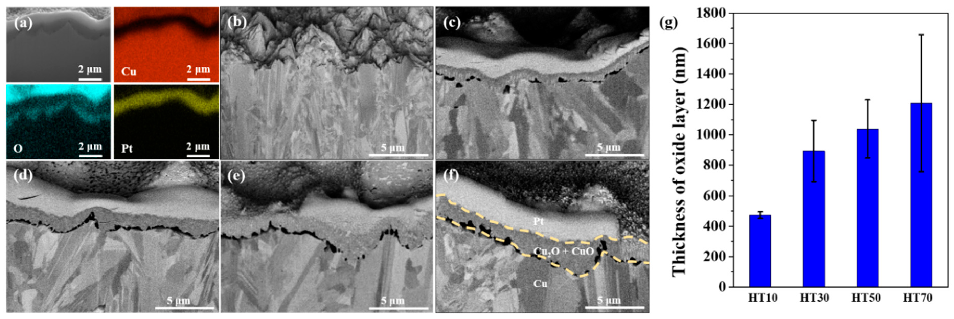
| HT10 | HT30 | HT50 | HT70 | |
|---|---|---|---|---|
| CuO/Cu2O | 0.1138 | 0.1331 | 0.1364 | 0.1422 |
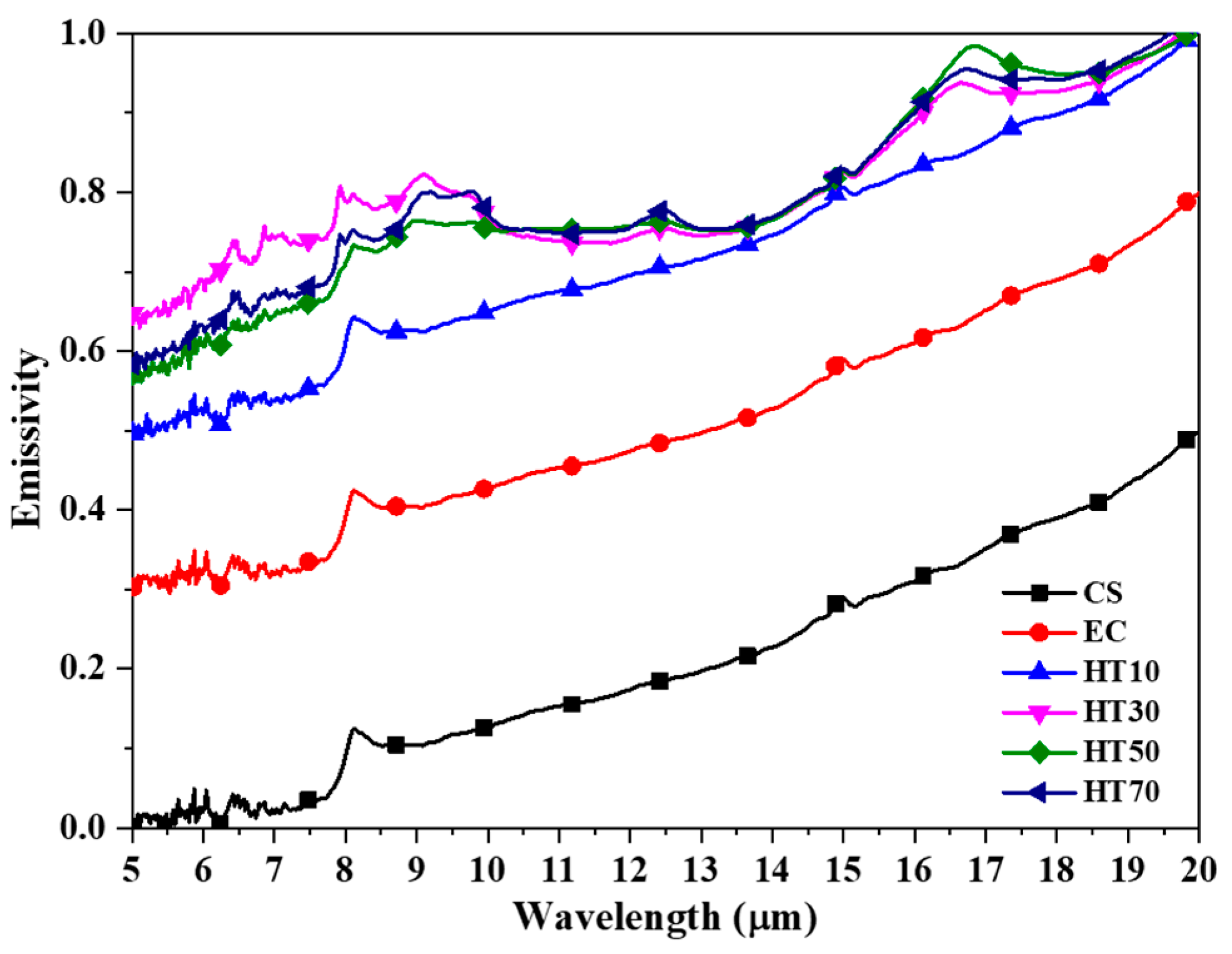
| CS | EC | HT10 | HT30 | HT50 | HT70 | |
|---|---|---|---|---|---|---|
| Emissivity | 0.279 | 0.579 | 0.794 | 0.857 | 0.861 | 0.865 |
Publisher’s Note: MDPI stays neutral with regard to jurisdictional claims in published maps and institutional affiliations. |
© 2021 by the authors. Licensee MDPI, Basel, Switzerland. This article is an open access article distributed under the terms and conditions of the Creative Commons Attribution (CC BY) license (https://creativecommons.org/licenses/by/4.0/).
Share and Cite
Park, J.; Kim, D.; Kim, H.; Lee, J.; Chung, W. Thermal Radiative Copper Oxide Layer for Enhancing Heat Dissipation of Metal Surface. Nanomaterials 2021, 11, 2819. https://doi.org/10.3390/nano11112819
Park J, Kim D, Kim H, Lee J, Chung W. Thermal Radiative Copper Oxide Layer for Enhancing Heat Dissipation of Metal Surface. Nanomaterials. 2021; 11(11):2819. https://doi.org/10.3390/nano11112819
Chicago/Turabian StylePark, Junghyun, Donghyun Kim, Hyunsik Kim, Junghoon Lee, and Wonsub Chung. 2021. "Thermal Radiative Copper Oxide Layer for Enhancing Heat Dissipation of Metal Surface" Nanomaterials 11, no. 11: 2819. https://doi.org/10.3390/nano11112819
APA StylePark, J., Kim, D., Kim, H., Lee, J., & Chung, W. (2021). Thermal Radiative Copper Oxide Layer for Enhancing Heat Dissipation of Metal Surface. Nanomaterials, 11(11), 2819. https://doi.org/10.3390/nano11112819