
Gas Phase Synthesis of Multi-Element Nanoparticles


Abstract

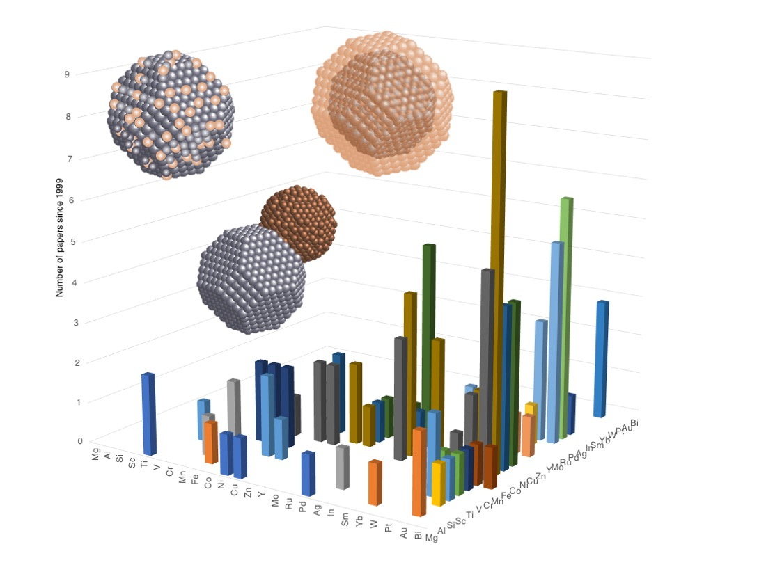
1. Introduction
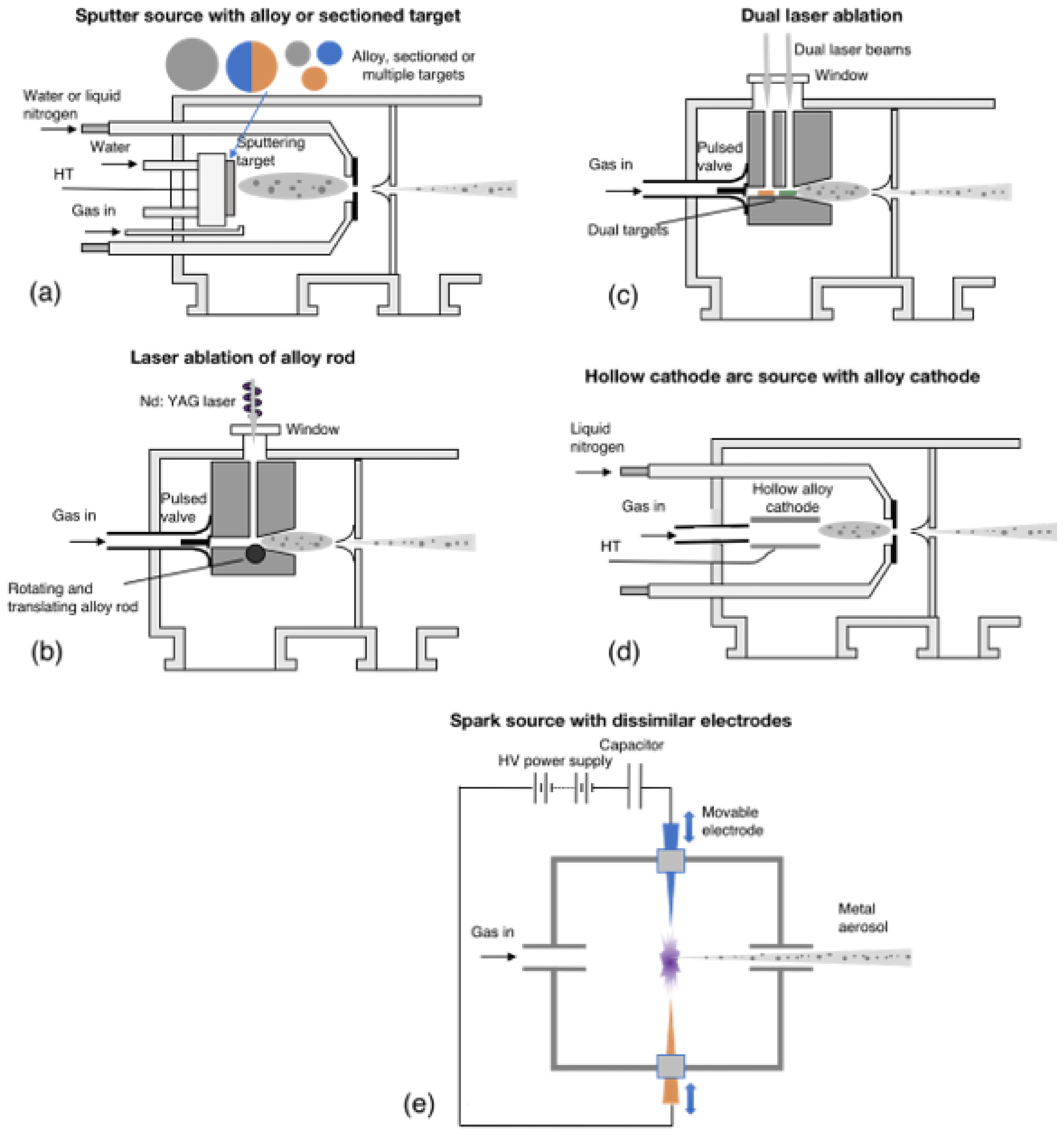
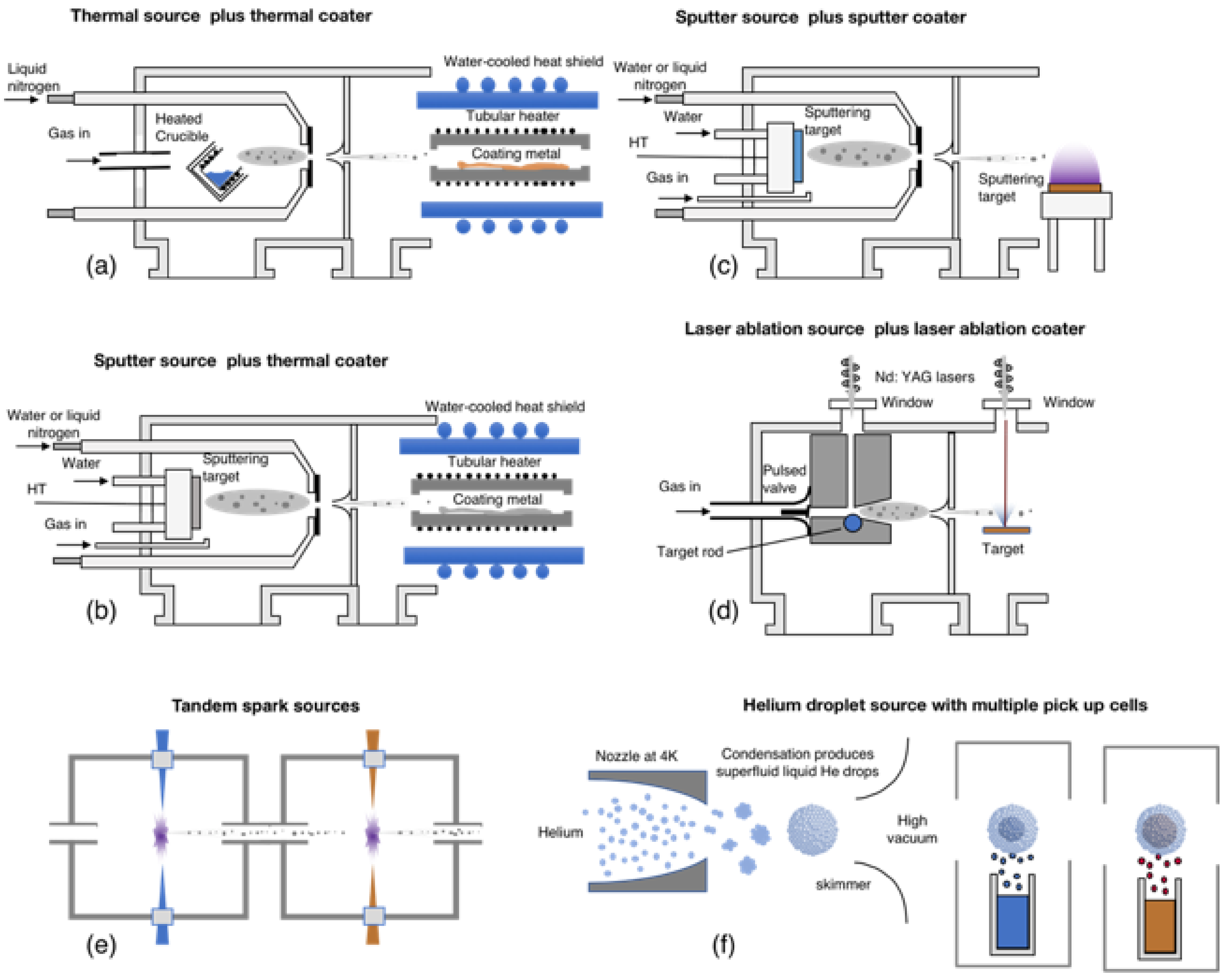
2. Gas Phase Methods for the Synthesis of Multi-Element Nanoparticles
3. Results
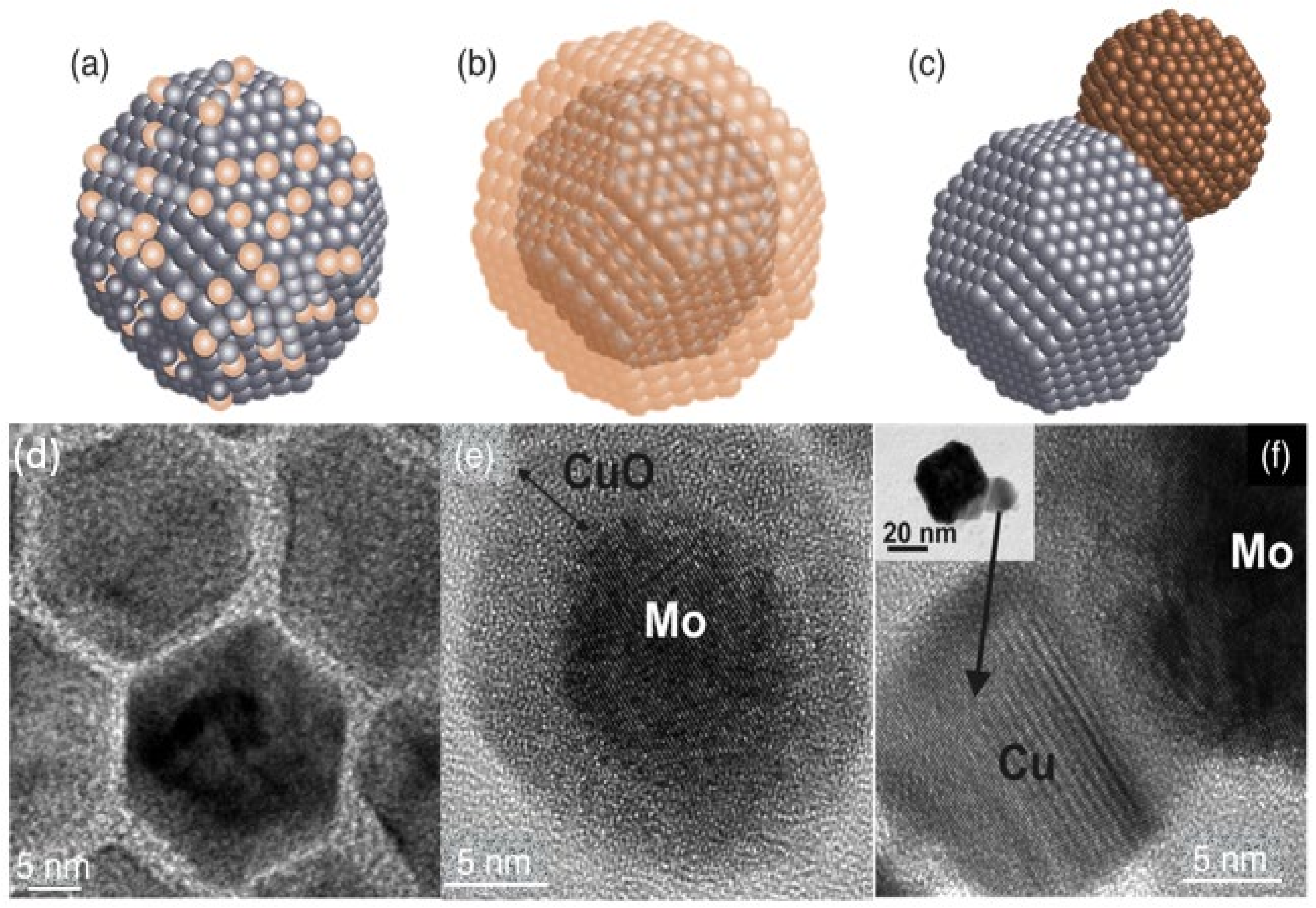
3.1. Two-Element Nanoparticles
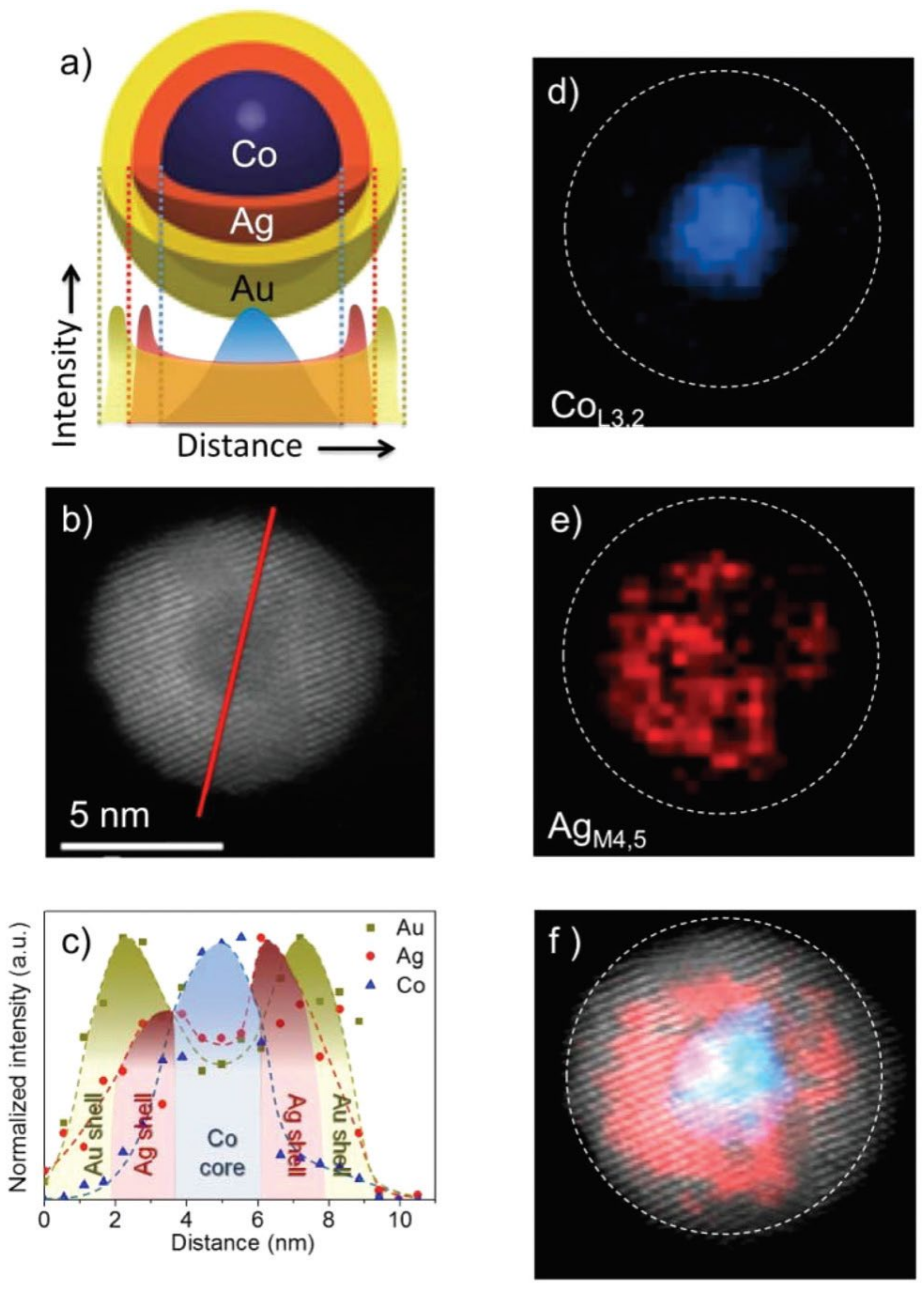
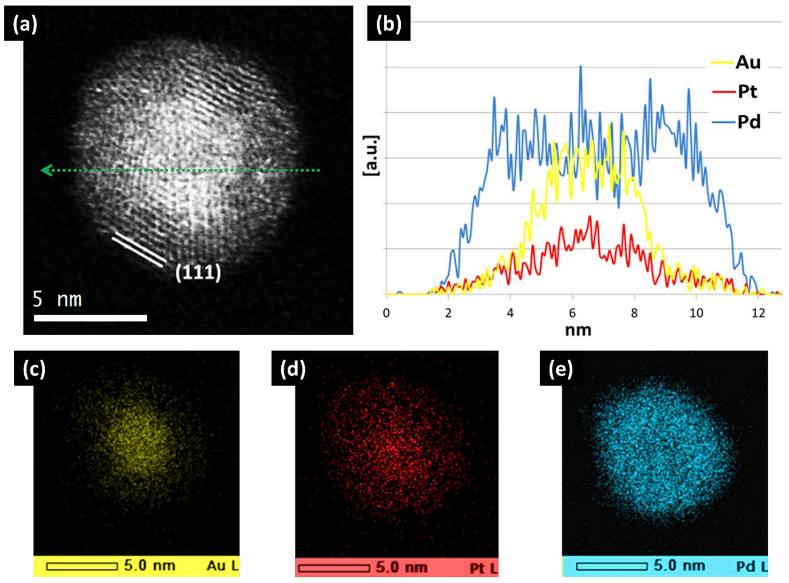
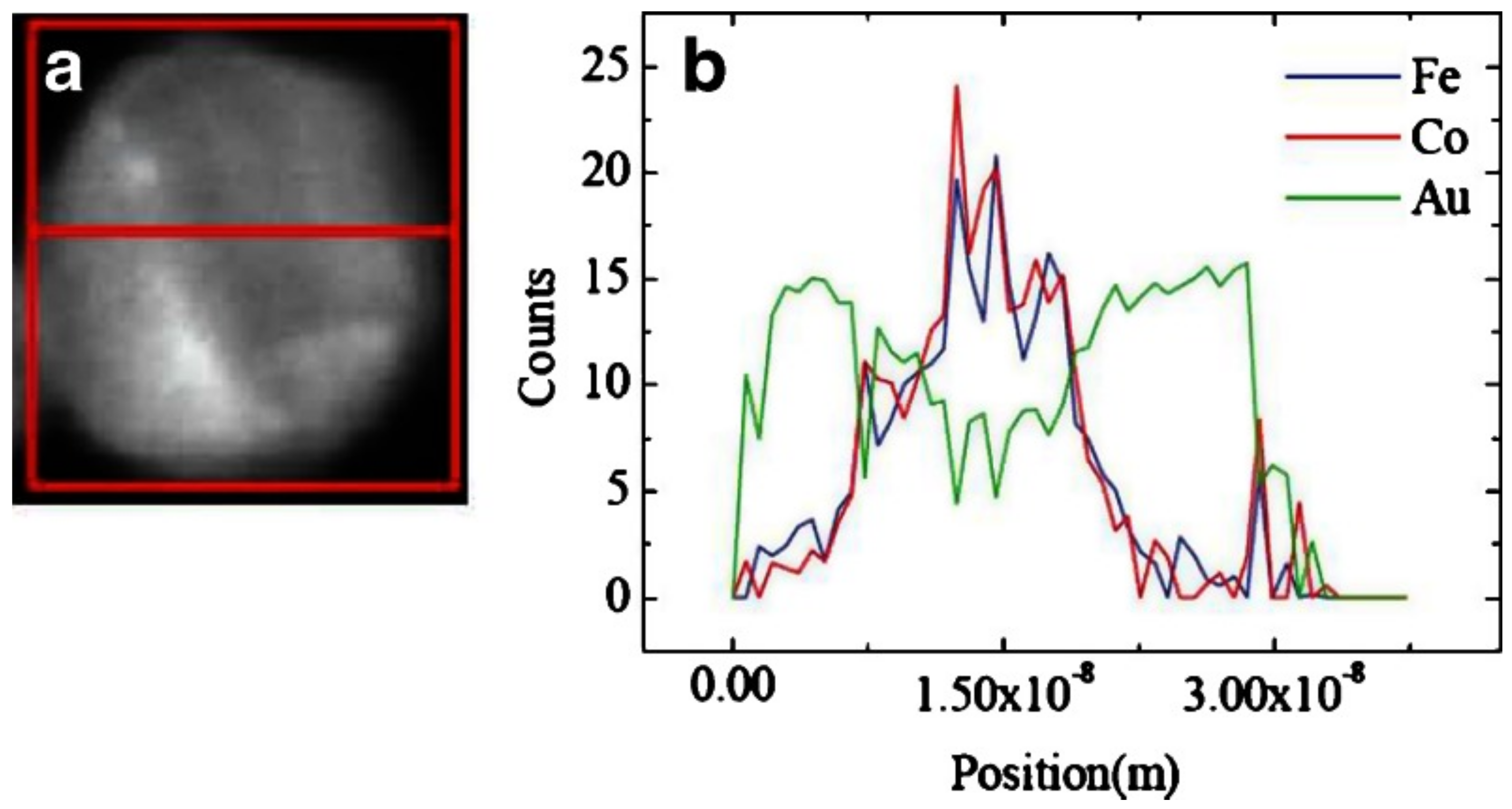
3.2. Three-Element Nanoparticles
4. Discussion
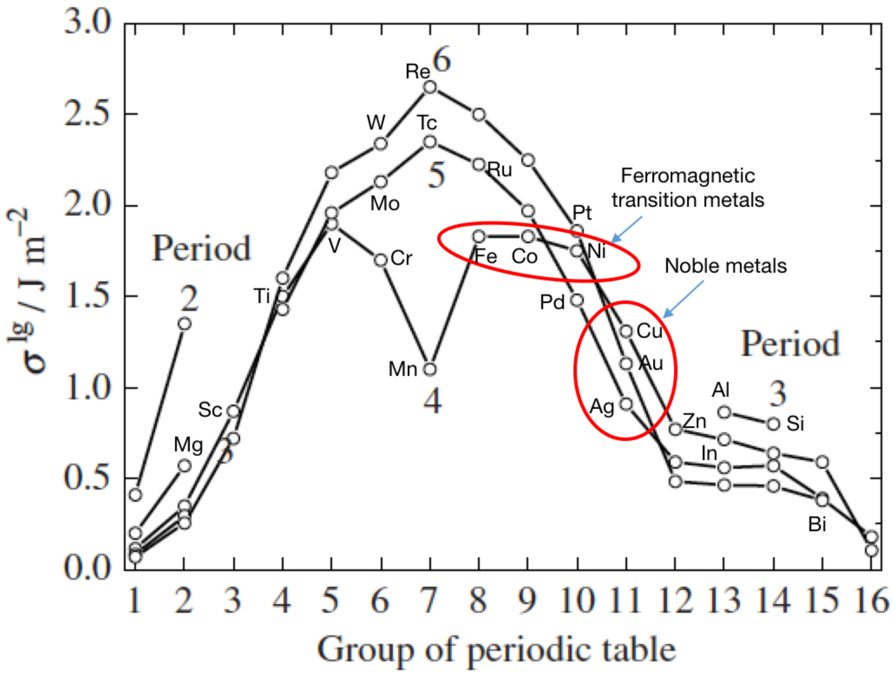
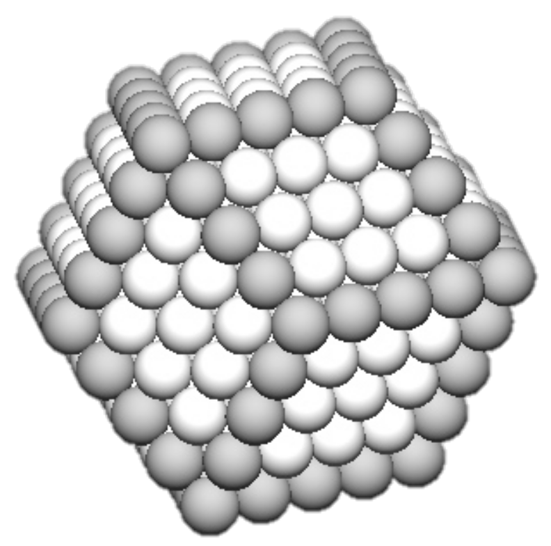
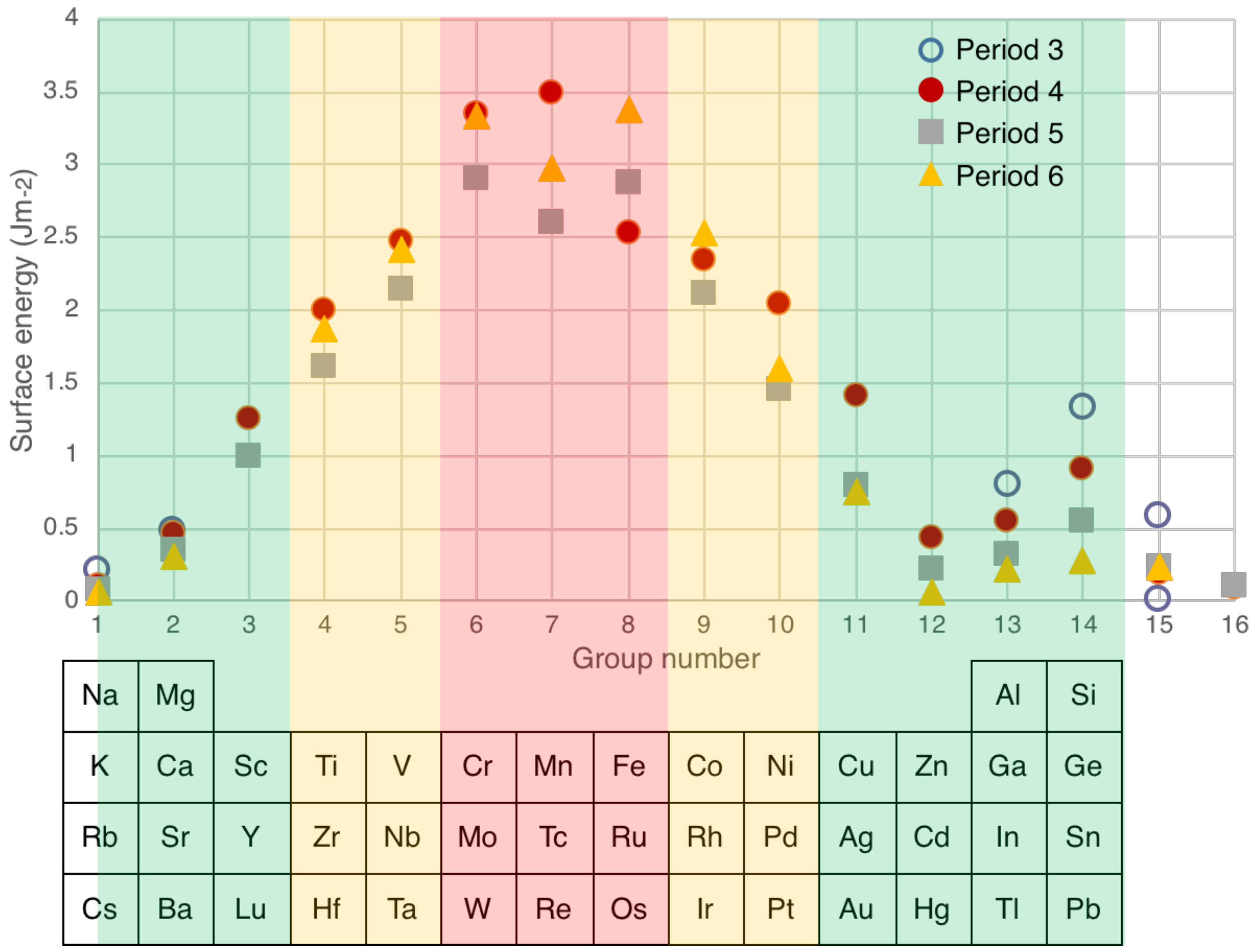
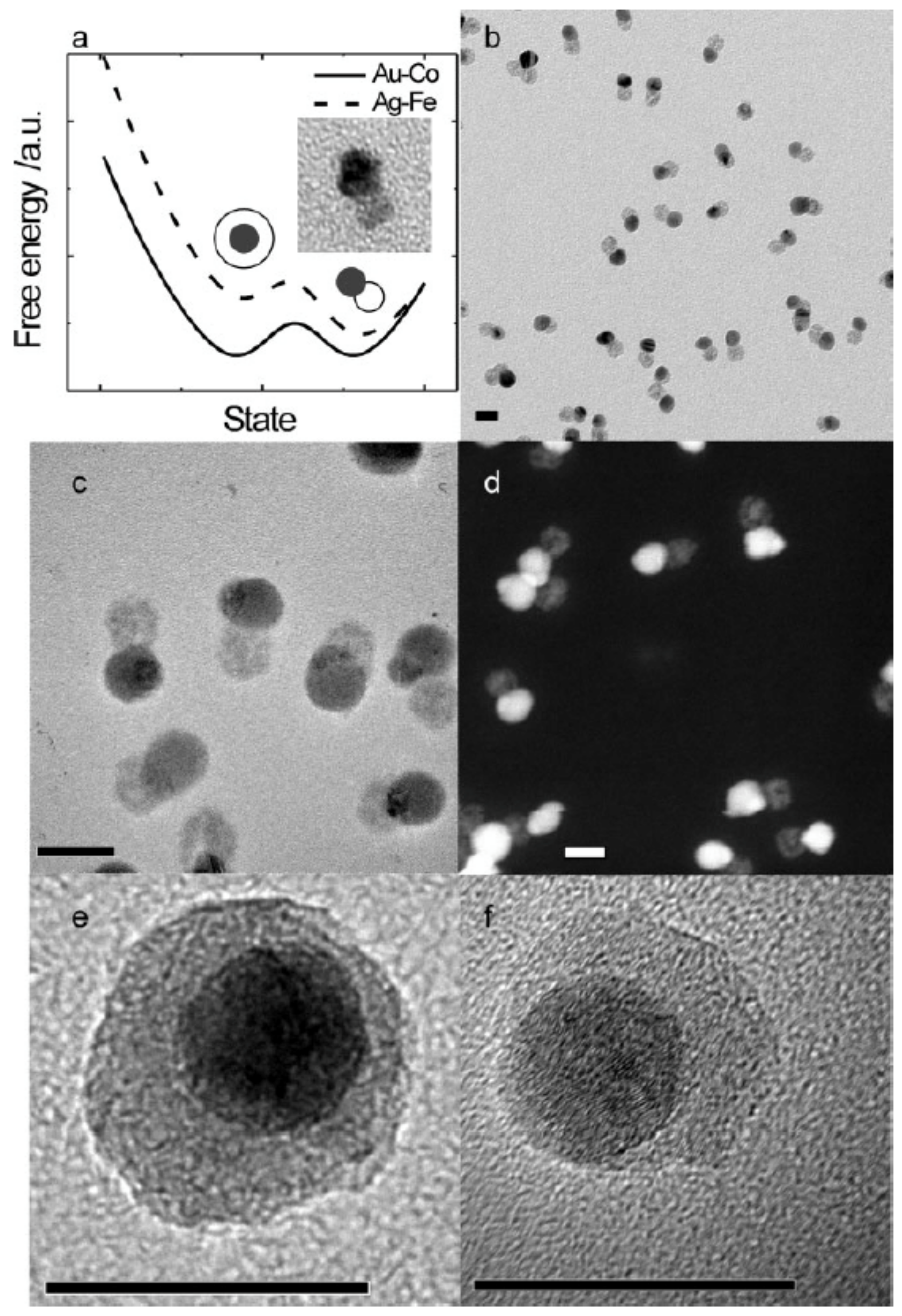
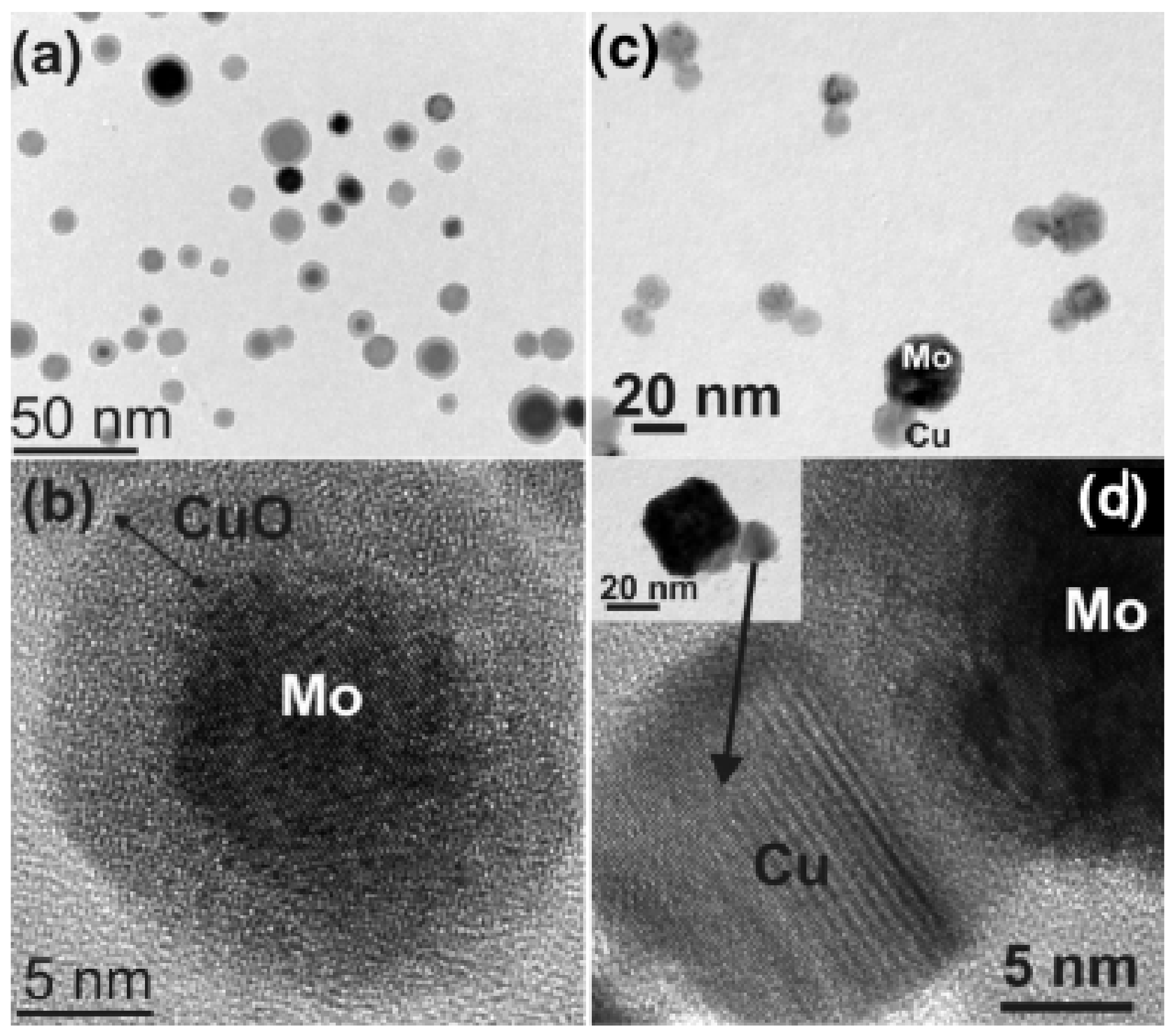
4.1. Surface Energies—Structures for Nanoparticles of Immiscible Elements
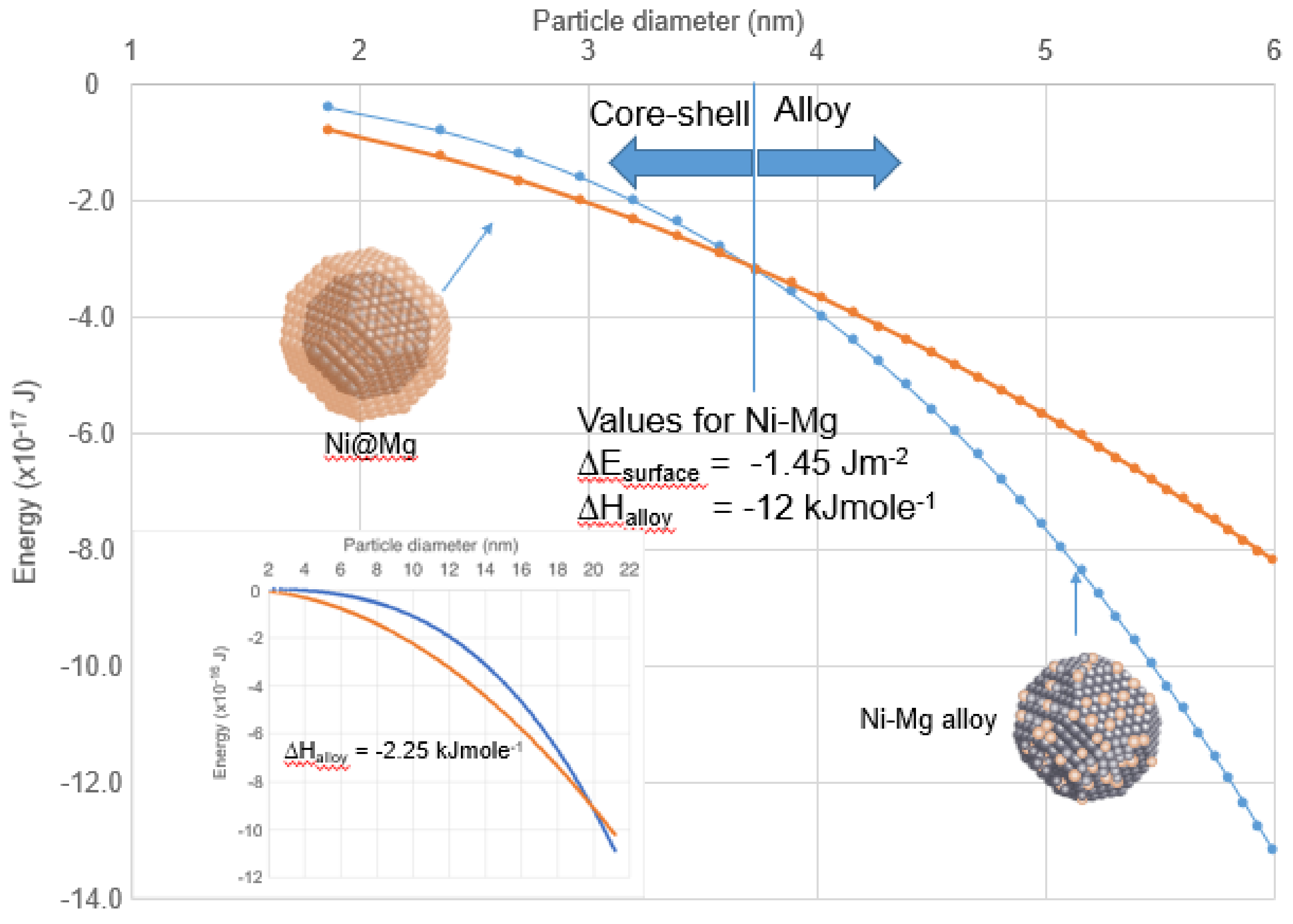
4.2. Enthalpy of Mixing—Structures for Nanoparticles of Miscible Elements
4.3. Core–Shell vs. Janus Structures
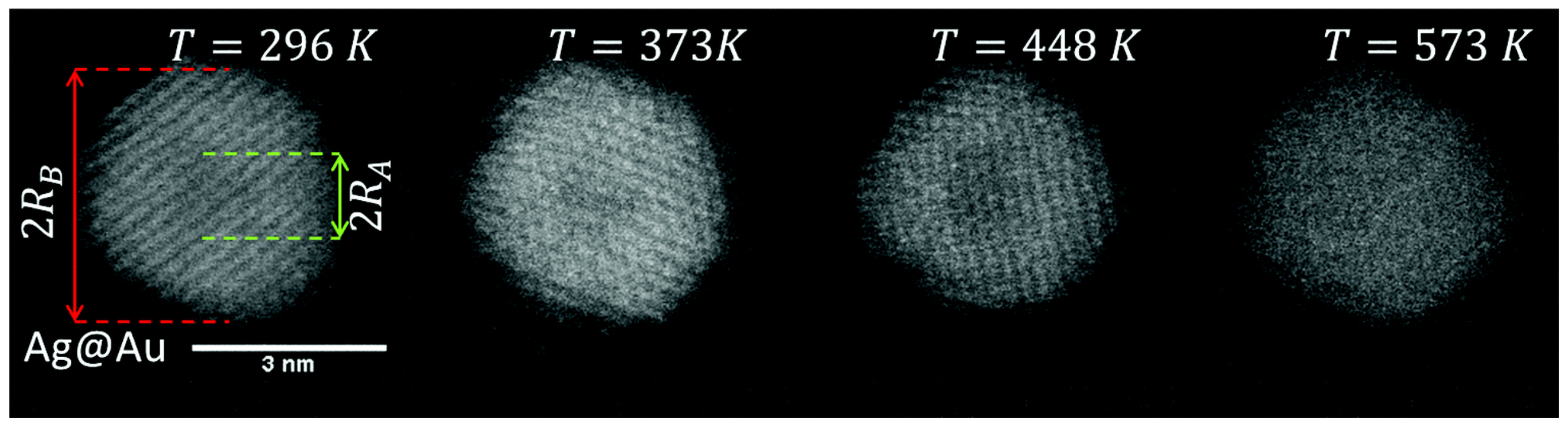
4.4. Non-Equilibrium Structures
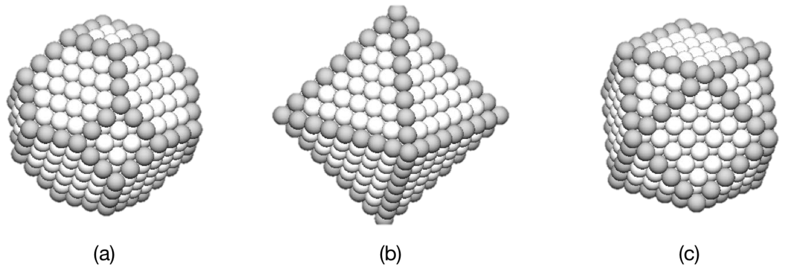
4.5. Other Structures
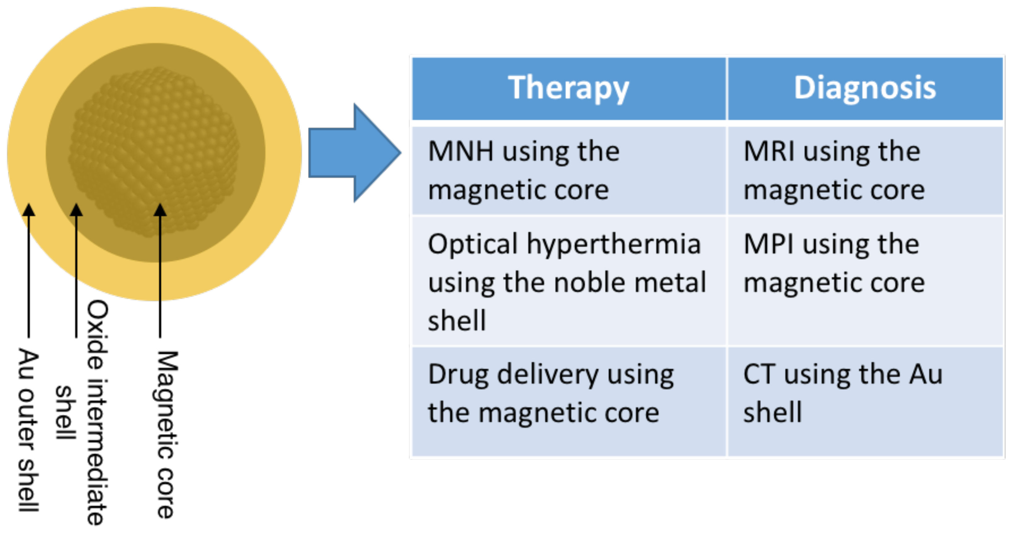
5. Technological Applications
6. Conclusions
Author Contributions
Funding
Conflicts of Interest
Appendix A

| Elements | Synthesis Method | Particle Size | Internal Structure | Comment | Reference | Elements | Synthesis Method | Particle Size | Internal Structure | Comment | Reference |
|---|---|---|---|---|---|---|---|---|---|---|---|
| AuCu, AuAl, AuY, AuIn | Dual laser ablation | 100 atoms | Dopants in small Au clusters | Au clusters doped with 1 or 2 atoms of other metals to study magic numbers (1999) | [30] | AuAl, AuFe, AuCo, AuNi | Dual laser ablation | ~10 atoms | Small AunXm clusters | Studied effect of time delay between laser pulses (2000) | [31] |
| AuCu | Laser ablation from alloy | ~2 nm | Alloy | Structural study. Atomic structure differed from bulk alloy (2001) | [118] | SmCo | Laser ablation from alloy | ~5 nm | Alloy | (2001) | [37] |
| AuSc, AuTi, AuV, AuCr, AuMn, AuFe, AuCo, AuNi | Dual laser ablation | <50 atoms | Dopants in small Au clusters | Study of magic numbers in Au clusters doped with transition metal atoms (2003) | [61] | NiAu, NiAg, CoAg | Laser ablation of alloy target | 2–5 nm | Ni@Au, Ni@Ag, Co@Ag | Size evolution of optical properties (2003) | [94] |
| SmCo | Sputter source with alloy target | 7 nm | Alloy | Magnetic properties of NPs before and after “in-flight” annealing (2003) | [97] | FePt | Sputter source with alloy target | 4–8 nm | Alloy | Phase transformation from the disordered fcc phase to ordered fct phase in FePt nanoparticles by “in-flight” annealing (2003) | [90] |
| FeCo | Hollow cathode arc source with alloy cathode | ~12 nm | Alloy | Formation of high-moment FeCo alloy nanoparticles (2004) | [79] | CoAg CoPt | Dual laser ablation | 2–4 nm | Alloy | Study of changes in magnetic anisotropy (2004) | [95] |
| CoSi | Sputter source with multiple targets | ~30 nm | Core–shell with Si rich shells | Magnetic properties of Co@Si clusters compared with Co@CoO (2005) | [56] | AuAg, AuPd | Laser ablation of alloy pellet | 8–22 nm | Alloy | Study of plasmon resonances (2006) | [131] |
| FePt | Sputter source with alloy target | 8 nm | Alloy | Obtention of ordered tetragonal phase (2006) | [91] | CoAu | Sputter source with alloy target | 5–15 nm | Co@Au | Magnetic behavior of Co@Au (2007) | [106] |
| AuPd | Sputter source with alloy target | 1–5 nm | Alloy | Icosahedral particles (2008) | [132] | CoAu, FeAg | Sputter source with alloy target | 12 nm (Au), ~15 nm (FeAg) | CoAu, Janus (FeAg) | Transition between core–shell and Janus structures (2008) | [86] |
| CrCo, AuPd, AgPd | Spark ablation source with alloy electrodes (CrCo) or different elemental electrodes (AuPd, AgPd) | 5–10 nm | Alloy | Comparison of elemental mixing using alloy or separate elemental electrodes (2008) | [73] | FeCu, FeAu | Thermal core plus thermal shell | ~2–3 nm | Core–shell | Modification of core atomic structure by changing the shell thickness (2010) | [81] |
| AgCu, CuW, PtAu | Spark ablation source with sintered electrodes (AgCu, CuW) or two different electrodes (PtAu) | ~5–8 nm | Alloy | Nanocrystalline phases found for AgCu and PtAu (2010) | [116] | AuPd | Sputter source with alloy target | 5 nm | Alloy | Study of the effect of temperature on structure (2010) | [133] |
| AuCo | Sputter source with sectioned target | 5 nm | Janus | HRTEM showed details of the Co/Au interface (2010) | [107] | YCo | Sputter source with sectioned target | <10 nm | Alloy | Study of magnetic behavior for different stoichiometries (2011) | [122] |
| AgFe | Sputter source with sectioned target | ~20 nm | Janus | In-flight thermal annealing performed (2011) | [88] | CoPt | Laser ablation of alloy target | 2–6 nm | Alloy | Morphology study of CoPt clusters (2011) | [100] |
| YCo | Sputter source with composite target | 8–10 nm | Alloy | Magnetic study of NPs with different crystal structures (2011) | [123] | AuCu | Sputter source with alloy target | ~4 nm | Graded alloy with either Cu-rich core or Au-rich core | (2011), instability of Au@Cu core–shell nanoparticles (Au diffused to the shell) (2012) | [119,120] |
| AgAu | Sputter sources with independent targets | <5 nm | Alloy | Fine tuning of the composition achieved via the multiple target cluster source (2012) | [33] | CuAg | Dual laser ablation | 12 nm | Co@Ag, Janus | Description of the transition from core–shell to Janus structures (2012) | [44] |
| FeCr | Thermal core plus thermal shell | 2.8 nm | Fe@Cr | Controlled shell thickness to observe onset of exchange bias (2013) | [34] | SmCo | Sputter source with sectioned target | ~40 nm | Alloy | Study of the growing mechanism and coercivity with sputter current (2013) | [98] |
| MoCu | Sputter source with segmented target | 10–60 nm | Alloy, core–shell, Janus | Structural motifs controlled by changing the source parameters (2013) | [23] | CoAu | Sputter source with alloy target | 10 nm | Alloy or Co@Au depending on deposition temperature | Magnetic and structural behavior of Co@Au with deposition temperature (2013) | [102] |
| MgNi, MgCu, MgTi | Sputter source with segmented target | 10–20 nm | Ni@Mg, Cu@Mg, Ti@Mg | Phase separation seen in the case of MgNi and MgCu to produce core–shell structure after hydrogenation (2014) | [48] | AuAg, AuCo | Sputter sources with 3 targets | 5–10 nm | Co@Au, Ag@Au | Changing the position of the magnetrons within the aggregation source enabled swapping core and shell materials (2014) | [103] |
| NiCu | Sputter source plus sputter coater | 20–50 nm | Ni@Cu | Shell thickness up to 5 nm (2014) | [108] | AlYb | Sputter source with sectioned target | 5–10 nm | Al@Yb | Oxidation experiments on the Yb shell (2014) | [55] |
| PtY | Sputter source with alloy target | 4–10 nm | Alloy in as-prepared samples, thin Pt-rich shell after oxidation | Study of PtY NPs as catalysts for the oxygen reduction reaction (2014) | [124] | AgSi | Sputter source with multiple targets | 4–15 nm | Core-satellite, Janus | Study of morphology by variation of operational parameters and MD study (2014) | [32] |
| FeAl | Sputter source with multiple targets | 10 nm | Fe@Al | Oxidation of the shell produces an alumina shell (2014) | [53] | AgCu | Liquid He droplet source | 2–5 nm | Ag@Au | Multiple cores observed above a critical size (2015) | [39] |
| PdMg | Sputter source with segmented target | ~5 nm | Pd@Mg | Synthesis of catalytic particles (2015) | [36] | AuCo | Sputter source with multiple targets | 8 nm | Co@Au | Icosahedral core–shell Co@Au nanoparticles and novel structure (icosahedral Co core surrounded by fcc Au facets) (2015) | [104] |
| NiCr | Sputter source with alloy target | 5 nm | Alloy | Deterioration of magnetic properties due to Cr segregation observed (2015) | [75] | TiV, PtV, PtTi | Sputter source with multiple targets | 5–8 nm | TiV alloy, V@Pt, TiPt alloy | Structure tunable with source parameters (2015) | [62] |
| RuPt | Sputter source with multiple targets | ~5 nm | Alloy | Electrochemical performance of RuPt alloy nanoparticles (2015) | [125] | CoAg, FeW, MoCo | Sputter source with composite target | 7–27 nm (CoAg), 5–15 nm (FeW), 2–10 nm (MoCo) | Co@Ag, W@Fe, Mo@Co | Minimum size for spontaneous core–shell formation (2015) | [89] |
| AgCu | Sputter source with multiple targets | 5–15 nm | Cu@Ag | Cu@Ag structure in Cu-rich particles and Ag@Cu@Ag in Ag-rich particles. “Ukidama” nanoparticles observed (2016) | [43] | FeCu | Sputter source plus thermal shell | ~20 nm | Alloy | (2016) | [82] |
| FeAg | Sputter source plus thermal shell | ~20 nm | Core with islanded shell (Janus) | (2016) | [87] | FeAu | Sputter source plus thermal shell | ~10 nm | Core–shell | (2016) | [82] |
| PtNi | Sputter source with alloy target | 1–2 nm | Alloy | High catalytic activity for methanol electro-oxidation when decorated on carbon nanotubes (2016) | [112] | NiCr | Sputter source with alloy target | 10–12 nm | Alloy | Study of Cr segregation and its effect on magnetic properties (2016) | [76] |
| MnBi | Sputter source with alloy target | ~10 nm | Bi@Mn or Mn@Bi@Mn | HRTEM study showing crystalline Bi and amorphous Mn (2016) | [77] | CoSi | Sputter source with composite target | ~18 nm | Alloy | Study of the coercivity of the NPs (2016) | [57] |
| MgTi | Sputter source with segmented target | ~20 nm | Ti@Mg | Showed nucleation induced by the introduction of trace gases (2017) | [47] | PdPt | Dual laser ablation | <6 nm | Pd@Pt | Study of hydrogen detection when deposited on ZnO nanorods (2017) | [127] |
| AgAu | Sputter source with sectioned target | 8–10 nm | Alloy | Characterization of AgAu in a SiO2 matrix (2017) | [135] | NiTi | Sputter source plus sputter coater | ~20 nm | Core–shell (Ni@Ti) | Demonstrated independent control of shell thickness (2017) | [64] |
| AgAu | Liquid He droplet source | 2 nm | Au@Ag or Ag@Au (depending on order of pick-up cells) transforming to alloy after annealing | HR TEM study of the alloying of metastable core–shell nanoparticles with annealing (2018) | [136] | AuCu | Sputter source with multiple targets | <5 nm | Alloy | Nanoparticles were deposited in MgO as catalysts (2018) | [121] |
| TiCu | Sputter source with alloy target | 8 nm | Alloy | Growth mechanism modelled by a nucleation model (2018) | [67] | CoAu | Sputter source with alloy target | 7 nm | Co@Au | Trimodal distribution and different structures when using pulsed sputtering instead of DC (2018) | [105] |
| MnSi | Sputter source with composite target | 10–20 nm | Alloy | Study of skyrmionic properties of NPs (2018) | [59] | NiMo | Sputter source with alloy target | 4 nm | Alloy | Production of NiMoS with a reactive atmosphere of H2S (2018) | [110] |
| PtTi | Sputter source with alloy target | 1–2 nm | Alloy, but becomes core–shell (Pt@Ti) with oxidation | Multicore Pt atoms observed after ambient exposure in the largest clusters (2018) | [69] | NiCu | Sputter source plus sputter coater | ~30 nm | Alloy | Enriched Cu shell observed for high Cu content (2019) | [109] |
| PdPt | Laser ablation of a sectioned plate | 11 nm | Alloy | Formation of nanoparticle graphene composites (2019) | [128] | AuPd | Sputter source plus sputter coater | 3 nm | Alloy | Even distribution of elements confirmed by EDS (2019) | [134] |
| FeAu | Sputter source with multiple targets | 10 nm | Core–shell (Fe@Au) and solid solution, where Au shell forms within the Fe core | FeAu nanocubes where Au occupied specific sites. Atomistic simulation of the growth mechanism (2019) | [93] | FeCr, FeMn | Spark ablation source with alloy electrodes plus thermal treatment | 10–50 nm | Fe@Cr, alloy, Janus (FeMn) | Incorporation of H2 as carrier gas led to core–shell morphologies, and subsequent annealing led to Janus FeMn nanoparticles (2019) | [71] |
| PdPt | Sputter source with multiple targets | <5 nm | Core–shell PtPd@Pt for Pt-rich and PtPd@Pd for Pd-rich | Out-of-equilibrium structures due to kinetic trapping. Verified by MD simulations (2020) | [129] | PdCu | Sputter source with multiple targets | 2–5 nm | alloy | Alloy nanoparticles deposited into liquid polymer (2020) | [114] |
| PtAu | Sputter source with multiple targets | 1.5–3.5 nm | Alloy | Deposition into liquid PEG. High Pt content prevented agglomeration (2020) | [138] | AuPt | Dual laser ablation | 2–3 nm | Alloy | UV sensitivity increased in ZnO decorated with nanoparticles (2020) | [139] |
| AgCu | Sputter source plus sputter coater | 10–20 nm | Janus | Coating with a tubular magnetron in which magnetic trapping increased thickness of the shell (2020) | [117] | CoCr | Sputter source with alloy target | 6–7 nm | alloy, Co@Cr, | Minimum size of nanoparticle for the spontaneous formation of Co@Cr (2020) | [74] |
| NiTi | Sputter source plus sputter coater | 15–20 nm | (Ni@Ti) | Ni@Ti NPs with thicker shells due to an arrow-shaped configuration of the aggregation chamber (2020) | [65] | AgAu | Sputter source with composite target | 5–20 nm | Alloy | Study of the effect of re-deposition in the composite target (2020) | [137] |
| ZnFe | Sputter source plus sputter coater | ~5 nm | Alloy | Particles formed a galvanic couple, promoting faster oxidation of Zn (2021) | [84] | ZnFe | Sputter source with multiple targets | ~20 nm | Fe@Zn/ZnO (Flower-like nanoparticles) | MD simulations used to understand particle growth (2021) | [85] |
References
- Binns, C. Chapter 1: Size Matters. In Introduction to Nanoscience and Nanotechnology, 2nd ed.; Wiley: Hoboken, NY, USA, 2021. [Google Scholar]
- Moshfegh, A.Z. Nanoparticle catalysts. J. Phys. D Appl. Phys. 2009, 42, 233001. [Google Scholar] [CrossRef]
- De Toro, J.A.; Normile, P.S.; Binns, C. Chapter 3: Types of Cluster Source. In Gas-Phase Synthesis of Nanoparticles; Huttel, Y., Ed.; Wiley-VCH: Weinheim, Germany, 2017; pp. 39–55. [Google Scholar]
- Knight, W.D.; Clemenger, K.; De Heer, W.A.; Saunders, W.A.; Chou, M.Y.; Cohen, M.L. Electronic shell structure and abundances of sodium clusters. Phys. Rev. Lett. 1984, 52, 2141–2143. [Google Scholar] [CrossRef]
- Blackman, J.A. Shell Models of Isolated Clusters. In Metallic Nanoparticles; Blackman, J.A., Ed.; Elsevier: Amsterdam, The Netherlands, 2008; pp. 17–46. [Google Scholar]
- Billas, I.M.L.; Chatalain, A.; De Heer, W.A. Magnetism from the Atom to the Bulk in Iron, Cobalt, and Nickel Clusters. Science 1994, 265, 1682–1684. [Google Scholar] [CrossRef]
- Cox, A.J.; Louderback, J.G.; Apsel, S.E.; Bloomfield, L.A. Magnetism in 4d-transition metal clusters. Phys. Rev. B 1994, 49, 12295–12298. [Google Scholar] [CrossRef]
- Apsel, S.E.; Emmert, J.W.; Deng, J.; Bloomfield, L.A. Surface-enhanced magnetism in nickel clusters. Phys. Rev. Lett. 1996, 76, 1441–1444. [Google Scholar] [CrossRef]
- Knickelbein, M.B. Adsorbate-induced enhancement of the magnetic moments of iron clusters. Chem. Phys. Lett. 2002, 19, 221–225. [Google Scholar] [CrossRef]
- Payne, F.W.; Jiang, W.; Emmert, J.W.; Deng, J.; Bloomfield, L.A. Magnetic structure of free cobalt clusters studied with Stern-Gerlach deflection experiments. Phys. Rev. B 2007, 75, 94431. [Google Scholar] [CrossRef]
- Link, S.; El-Sayed, M.A. Size and temperature dependence of the plasmon absorption of colloidal gold nanoparticles. J. Phys. Chem. B 1999, 103, 4212–4217. [Google Scholar] [CrossRef]
- Halas, N.J.; Lal, S.; Chang, W.-S.; Link, S.; Nordlander, P. Plasmons in Strongly Coupled Metallic Nanostructures. Chem. Rev. 2011, 111, 3913–3961. [Google Scholar] [CrossRef]
- Cushing, B.L.; Kolesnichenko, V.L.; O’Connor, C.J. Recent Advances in the Liquid-Phase Syntheses of Inorganic Nanoparticles. Chem. Rev. 2004, 104, 3893–3946. [Google Scholar] [CrossRef] [PubMed]
- Pastoriza-Santos, I.; Liz-Marzán, L.M. Formation and Stabilization of Silver Nanoparticles through Reduction by N.N-Dimethylformamide. Langmuir 1999, 15, 948–951. [Google Scholar] [CrossRef]
- Oliveira, M.M.; Schnitzler, D.C.; Zarbin, A.J.G. (Ti,Sn)O2 Mixed Oxides Nanoparticles Obtained by the Sol–Gel Route. Chem. Mater. 2003, 15, 1903–1909. [Google Scholar] [CrossRef]
- Staniland, S.; Williams, W.; Telling, N.; Van Der Laan, G.; Harrison, A.; Ward, B. Controlled cobalt doping of magnetosomes in vivo. Nat. Nanotechnol. 2008, 3, 158–162. [Google Scholar] [CrossRef] [PubMed]
- Coker, V.S.; Telling, N.D.; Van Der Laan, G.; Pattrick, R.A.D.; Pearce, C.I.; Arenholz, E.; Tuna, F.; Winpenny, R.E.P.; Lloyd, J.R. Harnessing the extracellular bacterial production of nanoscale cobalt ferrite with exploitable magnetic properties. ACS Nano 2009, 3, 1922–1928. [Google Scholar] [CrossRef] [PubMed]
- Chakka, V.M.; Altuncevahir, B.; Jin, Z.Q.; Li, Y.; Liu, J.P. Magnetic nanoparticles produced by surfactant-assisted ball milling. J. Appl. Phys. 2006, 99, 08E912. [Google Scholar] [CrossRef]
- Hu, Z.; Oskam, G.; Searson, P.C. Influence of solvent on the growth of ZnO nanoparticles. J. Colloid Interface Sci. 2003, 263, 454–460. [Google Scholar] [CrossRef]
- Stappen, F.N.; Enemark-Rasmussen, K.; Junor, G.P.; Clausen, M.H.; Zhang, J.; Engelbrekt, C. Implications of Byproduct Chemistry in Nanoparticle Synthesis. J. Phys. Chem. C 2019, 123, 25402–25411. [Google Scholar] [CrossRef]
- Rossi, L.M.; Fiorio, J.L.; Garcia, M.A.S.; Ferraz, C.P. The role and fate of capping ligands in colloidally prepared metal nanoparticle catalysts. Dalt. Trans. 2018, 47, 5889–5915. [Google Scholar] [CrossRef]
- Wang, D.; Xhao, P.; Li, Y. General preparation for Pt-based alloy nanoporous nanoparticles as potential nanocatalysts. Sci. Rep. 2011, 1, 37. [Google Scholar] [CrossRef]
- Krishnan, G.; Verheijen, M.A.; ten Brink, G.H.; Palasantzas, G.; Kooi, B.J. Tuning structural motifs and alloying of bulk immiscible Mo–Cu bimetallic nanoparticles by gas-phase synthesis. Nanoscale 2013, 5, 5375–5383. [Google Scholar] [CrossRef]
- Baker, S.H.; Thornton, S.C.; Edmonds, K.W.; Maher, M.J.; Norris, C.; Binns, C. The construction of a gas aggregation source for the preparation of size-selected nanoscale transition metal clusters. Rev. Sci. Instrum. 2000, 71, 3178–3183. [Google Scholar] [CrossRef]
- Milani, P.; deHeer, W.A. Improved pulsed laser vaporization source for production of intense beams of neutral and ionized clusters. Rev. Sci. Instrum. 1990, 61, 1835–1838. [Google Scholar] [CrossRef]
- Haberland, H.; Karrais, M.; Mall, M.; Thurner, Y. Thin films from energetic cluster impact: A feasibility study. J. Vac. Sci. Technol. 1992, 10, 3266–3271. [Google Scholar] [CrossRef]
- Siekmann, H.R.; Luder, C.; Faehrmann, J.; Lutz, H.O.; Meiwes-Broer, K.H. The pulsed arc cluster ion source (PACIS). Z. Phys. D Mol. Clust. 1991, 20, 417–420. [Google Scholar] [CrossRef]
- Pfeiffer, T.V.; Feng, J.; Schmidt-Ott, A. New developments in spark production of nanoparticles. Adv. Powder Technol. 2014, 25, 56–70. [Google Scholar] [CrossRef]
- Briehl, B.; Urbassek, H.M. Monte Carlo simulation of growth and decay processes in a cluster aggregation source. J. Vac. Sci. Technol. 1999, 17, 256–265. [Google Scholar] [CrossRef]
- Bouwen, W.; Vanhoutte, F.; Despa, F.; Bouckaert, S.; Neukermans, S.; Theil Kuhn, L.; Weidele, H.; Lievens, P.; Silverans, R.E. Stability effects of AunXm+ (X = Cu, Al, Y, In) clusters. Chem. Phys. Lett. 1999, 314, 227–233. [Google Scholar] [CrossRef]
- Bouwen, W.; Thoen, P.; Vanhoutte, F.; Bouckaert, S.; Despa, F.; Weidele, H.; Silverans, R.E.; Lievens, P. Production of bimetallic clusters by a dual-target dual-laser vaporization source. Rev. Sci. Instrum. 1999, 71, 54–58. [Google Scholar] [CrossRef]
- Singh, V.; Cassidy, C.; Grammatikopoulos, P.; Djurabekova, F.; Nordlund, K.; Sowwan, M. Heterogeneous Gas-Phase Synthesis and Molecular Dynamics Modeling of Janus and Core–Satellite Si–Ag Nanoparticles. J. Phys. Chem. C 2014, 118, 13869–13875. [Google Scholar] [CrossRef]
- Martínez, L.; Díaz, M.; Román, E.; Ruano, M.; Llamosa, P.D.; Huttel, Y. Generation of Nanoparticles with Adjustable Size and Controlled Stoichiometry: Recent Advances. Langmuir 2012, 28, 11241–11249. [Google Scholar] [CrossRef]
- Binns, C.; Qureshi, M.T.; Peddis, D.; Baker, S.H.; Howes, P.B.; Boatwright, A.; Cavill, S.A.; Dhesi, S.S.; Lari, L.; Kröger, R.; et al. Exchange Bias in Fe@Cr Core–Shell Nanoparticles. Nano Lett. 2013, 13, 3334–3339. [Google Scholar] [CrossRef] [PubMed][Green Version]
- Binns, C.; Prieto, P.; Baker, S.; Howes, P.; Dondi, R.; Burley, G.; Lari, L.; Kröger, R.; Pratt, A.; Aktas, S.; et al. Preparation of hydrosol suspensions of elemental and core–shell nanoparticles by co-deposition with water vapour from the gas-phase in ultra-high vacuum conditions. J. Nanoparticle Res. 2012, 14, 1136. [Google Scholar] [CrossRef]
- Singh, V.; Cassidy, C.; Abild-Pedersen, F.; Kim, J.-H.; Aranishi, K.; Kumar, S.; Lal, C.; Gspan, C.; Grogger, W.; Sowwan, M. Engineering high-performance Pd core–MgO porous shell nanocatalysts via heterogeneous gas-phase synthesis. Nanoscale 2015, 7, 13387–13392. [Google Scholar] [CrossRef] [PubMed]
- Perez, A.; Melinon, P.; Dupuis, V.; Prevel, B.; Bardotti, L.; Tuaillon-Combes, J.; Masenelli, B.; Treilleux, M.; Pellarin, M.; Lerme, J.; et al. Nanostructured Materials from Clusters: Synthesis and Properties. Mater. Trans. 2001, 42, 1460–1470. [Google Scholar] [CrossRef]
- Boatwright, A.; Feng, C.; Spence, D.; Latimer, E.; Binns, C.; Ellis, A.M.; Yang, S. Helium droplets: A new route to nanoparticles. Faraday Discuss. 2013, 162, 113–124. [Google Scholar] [CrossRef] [PubMed]
- Thaler, P.; Volk, A.; Knez, D.; Lackner, F.; Haberfehlner, G.; Steurer, J.; Schnedlitz, M.; Ernst, W.E. Synthesis of nanoparticles in helium droplets—A characterization comparing mass-spectra and electron microscopy data. J. Chem. Phys. 2015, 143, 134201. [Google Scholar] [CrossRef]
- Yang, S.; Feng, C.; Spence, D.; Al Hindawi, A.M.A.A.; Latimer, E.; Ellis, A.M.; Binns, C.; Peddis, D.; Dhesi, S.S.; Zhang, L.; et al. Robust Ferromagnetism of Chromium Nanoparticles Formed in Superfluid Helium. Adv. Mater. 2017, 29, 1604277. [Google Scholar] [CrossRef]
- Mattei, J.-G.; Grammatikopoulos, P.; Zhao, J.; Singh, V.; Vernieres, J.; Steinhauer, S.; Porkovich, A.; Danielson, E.; Nordlund, K.; Djurabekova, F.; et al. Gas-Phase Synthesis of Trimetallic Nanoparticles. Chem. Mater. 2019, 31, 2151–2163. [Google Scholar] [CrossRef]
- Andreazza, P.; Lemoine, A.; Coati, A.; Nelli, D.; Ferrando, R.; Garreau, Y.; Creuze, J.; Andreazza-Vignolle, C. From metastability to equilibrium during the sequential growth of Co–Ag supported clusters: A real-time investigation. Nanoscale 2021, 13, 6096–6104. [Google Scholar] [CrossRef]
- Grammatikopoulos, P.; Kioseoglou, J.; Galea, A.; Vernieres, J.; Benelmekki, M.; Diaz, R.E.; Sowwan, M. Kinetic trapping through coalescence and the formation of patterned Ag–Cu nanoparticles. Nanoscale 2016, 8, 9780–9790. [Google Scholar] [CrossRef]
- Langlois, C.; Li, Z.L.; Yuan, J.; Alloyeau, D.; Nelayah, J.; Bochicchio, D.; Ferrando, R.; Ricolleau, C. Transition from core–shell to Janus chemical configuration for bimetallic nanoparticles. Nanoscale 2012, 4, 3381–3388. [Google Scholar] [CrossRef]
- Shyrokorad, D.; Kornich, G.; Buga, S. Formation of the core-shell structures from bimetallic Janus-like nanoclusters under low-energy Ar and Ar13 impacts: A molecular dynamics study. Comput. Mater. Sci. 2019, 159, 110–119. [Google Scholar] [CrossRef]
- De Boer, F.R.; Boom, R.; Mattens, W.C.M.; Miedema, A.R.; Niessen, A.K. Cohesion in Metals: Transition Metal Alloys. North-Holland Physics; Elsevier: Amsterdam, The Netherlands, 1988. [Google Scholar]
- Krishnan, G.; de Graaf, S.; ten Brink, G.H.; Persson, P.O.Å.; Kooi, B.J.; Palasantzas, G. Strategies to initiate and control the nucleation behavior of bimetallic nanoparticles. Nanoscale 2017, 9, 8149–8156. [Google Scholar] [CrossRef]
- Krishnan, G.; Negrea, R.F.; Ghica, C.; ten Brink, G.H.; Kooi, B.J.; Palasantzas, G. Synthesis and exceptional thermal stability of Mg-based bimetallic nanoparticles during hydrogenation. Nanoscale 2014, 6, 11963–11970. [Google Scholar] [CrossRef]
- Mezbahul-Islam, M.; Medraj, M. A critical thermodynamic assessment of the Mg–Ni, Ni–Y binary and Mg–Ni–Y ternary systems. Calphad Comput. Coupling Phase Diagr. Thermochem. 2009, 33, 478–486. [Google Scholar] [CrossRef]
- Feufel, H.; Sommer, F. Thermodynamic investigations of binary liquid and solid CuMg and MgNi alloys and ternary liquid CuMgNi alloys. J. Alloy. Compd. 1995, 224, 42–54. [Google Scholar] [CrossRef]
- Dębski, A.A.; Terlicka, S.; Gąsior, W.; Gierlotka, W.; Pęska, M.; Polański, M. Thermodynamic properties of Mg-Pd liquid alloys. J. Mol. Liq. 2020, 317, 114024. [Google Scholar] [CrossRef]
- Feutelais, K.Y.; Legendre, B.; Guymont, M.; Ochin, P. Standard enthalpy of formation of AI 28Fe72 at 298 K. J. Alloy. Compd. 2001, 322, 184–189. [Google Scholar] [CrossRef]
- Vernieres, J.; Benelmekki, M.; Kim, J.-H.; Grammatikopoulos, P.; Bobo, J.-F.; Diaz, R.E.; Sowwan, M. Single-step gas phase synthesis of stable iron aluminide nanoparticles with soft magnetic properties. APL Mater. 2014, 2, 116105. [Google Scholar] [CrossRef]
- Meng, F.G.; Zhang, L.G.; Liu, H.S.; Liu, B.L.; Jin, Z.P. Thermodynamic optimization of the Al–Yb binary system. J. Alloy. Compd. 2008, 452, 279–282. [Google Scholar] [CrossRef]
- Zhang, C.; Andersson, T.; Mikkelä, M.-H.; Mårsell, E.; Björneholm, O.; Xu, X.; Tchaplyguine, M.; Liu, Z. Alloying and oxidation of in situ produced core-shell Al@Yb nanoalloy particles—An “on-the-fly” study. J. Chem. Phys. 2014, 141, 84302. [Google Scholar] [CrossRef]
- Sumiyama, K.; Hihara, T.; Liang Peng, D.; Katoh, R. Structure and magnetic properties of Co/CoO and Co/Si core-shell assemblies prepared via gas-phase. Sci. Technol. Adv. Mater. 2005, 6, 18–26. [Google Scholar] [CrossRef]
- Balasubramanian, B.; Manchanda, P.; Skomski, R.; Mukherjee, P.; Valloppilly, S.R.; Das, B.; Hadjipanayis, G.C.; Sellmyer, D.J. High-coercivity magnetism in nanostructures with strong easy-plane anisotropy. Appl. Phys. Lett. 2016, 108, 152406. [Google Scholar] [CrossRef]
- Miettinen, J.; Visuri, V.-V.; Fabritius, T. Thermodynamic Descritption of the Fe-Al-Mn-Si-C system for modelling solidification of steels. In Acta Universitatis Oulouensis C Technica 704; University of Oulu: Oulu, Finland, 2019. [Google Scholar]
- Das, B.; Balasubramanian, B.; Skomski, R.; Mukherjee, P.; Valloppilly, S.R.; Hadjipanayis, G.C.; Sellmyer, D.J. Effect of size confinement on skyrmionic properties of MnSi nanomagnets. Nanoscale 2018, 10, 9504–9508. [Google Scholar] [CrossRef] [PubMed]
- Oleslnski, R.W.; Gokhale, A.B.; Abbaschlan, J.G. The Ag-Si Ssystem. Bull. Alloy. Phase Diagr. 1989, 10, 635–640. [Google Scholar] [CrossRef]
- Neukermans, S.; Janssens, E.; Tanaka, H.; Silverans, R.E.; Lievens, P. Element- and size-sependent slectron delocalization in AuNX clusters (X = Ti, V, Cr, Mn, Fe, Co, Ni). Phys. Rev. Lett. 2003, 90, 33401. [Google Scholar] [CrossRef] [PubMed]
- Johnson, G.E.; Colby, R.; Laskin, J. Soft landing of bare nanoparticles with controlled size, composition, and morphology. Nanoscale 2015, 7, 3491–3503. [Google Scholar] [CrossRef]
- Guoa, Q.; Kleppa, O.J. The standard enthalpies of formation of the compounds of early transition metals with late transition metals and with noble metals as determined by Kleppa and co-workers at the University of Chicago—A review. J. Alloys Compd. 2001, 321, 169–182. [Google Scholar] [CrossRef]
- Hanuš, J.; Vaidulych, M.; Kylián, O.; Choukourov, A.; Kousal, J.; Khalakhan, I.; Cieslar, M.; Solař, P.; Biederman, H. Fabrication of Ni@Ti core–shell nanoparticles by modified gas aggregation source. J. Phys. D Appl. Phys. 2017, 50, 475307. [Google Scholar] [CrossRef]
- Solař, P.; Hanuš, J.; Cieslar, M.; Košutová, T.; Škorvánková, K.; Kylián, O.; Kúš, P.; Biederman, H. Composite Ni@Ti nanoparticles produced in arrow-shaped gas aggregation source. J. Phys. D Appl. Phys. 2020, 53, 195303. [Google Scholar] [CrossRef]
- Turchanin, M.A.; Agraval, P.G.; Fesenko, A.N.; Abdulov, A.R. Thermodynamics of liquid alloys and phase transformations in the copper-titanium system. Powder Metall. Met. Ceram. 2005, 44, 259–270. [Google Scholar] [CrossRef]
- Ayesh, A.I. Size-selected fabrication of alloy nanoclusters by plasma-gas condensation. J. Alloy. Compd. 2018, 745, 299–305. [Google Scholar] [CrossRef]
- Guo, Q.; Kleppa, O.J. Standard enthalpies of formation of some alloys formed between Group IV elements and Group VIII elements, determined by high-temperature direct synthesis calorimetry: I. Alloys of (Ti, Zr, Hf) with (Rh, Pd, Pt). J. Alloy. Compd. 1998, 266, 224–229. [Google Scholar] [CrossRef]
- Gholhaki, S.; Hung, S.-H.; Cant, D.J.H.; Blackmore, C.E.; Shard, A.G.; Guo, Q.; McKenna, K.P.; Palmer, R.E. Exposure of mass-selected bimetallic Pt–Ti nanoalloys to oxygen explored using scanning transmission electron microscopy and density functional theory. RSC Adv. 2018, 8, 27276–27282. [Google Scholar] [CrossRef]
- Bennett, L.H.; Watson, R.E. A database for enthalpies of formation of binary transition metal alloys. CALPHAD 1981, 5, 19–23. [Google Scholar] [CrossRef]
- Preger, C.; Bulbucan, C.; Meuller, B.O.; Ludvigsson, L.; Kostanyan, A.; Muntwiler, M.; Deppert, K.; Westerström, R.; Messing, M.E. Controlled Oxidation and Self-Passivation of Bimetallic Magnetic FeCr and FeMn Aerosol Nanoparticles. J. Phys. Chem. C 2019, 123, 16083–16090. [Google Scholar] [CrossRef]
- Downie, D.B.; Arslan, F. Enthalpies of formation of (cobalt + chromium) alloys at 473 K. J. Chem. Thermodyn. 1983, 15, 645–649. [Google Scholar] [CrossRef]
- Tabrizi, N.S.; Xu, Q.; van der Pers, N.M.; Lafont, U.; Schmidt-Ott, A. Synthesis of mixed metallic nanoparticles by spark discharge. J. Nanoparticle Res. 2008, 11, 1209. [Google Scholar] [CrossRef]
- Soler-Morala, J.; Jefremovas, E.M.; Martínez, L.; Mayoral, Á.; Sánchez, E.H.; De Toro, J.A.; Navarro, E.; Huttel, Y. Spontaneous Formation of Core@shell Co@Cr Nanoparticles by Gas Phase Synthesis. Appl. Nano 2020, 1, 87–101. [Google Scholar] [CrossRef]
- Bohra, M.; Grammatikopoulos, P.; Diaz, R.E.; Singh, V.; Zhao, J.; Bobo, J.-F.; Kuronen, A.; Djurabekova, F.; Nordlund, K.; Sowwan, M. Surface Segregation in Chromium-Doped NiCr Alloy Nanoparticles and Its Effect on Their Magnetic Behavior. Chem. Mater. 2015, 27, 3216–3225. [Google Scholar] [CrossRef]
- Bohra, M.; Singh, V.; Grammatikopoulos, P.; Toulkeridou, E.; Diaz, R.E.; Bobo, J.F.; Sowwan, M. Control of Surface Segregation in Bimetallic NiCr Nanoalloys Immersed in Ag Matrix. Sci. Rep. 2016, 6, 19153. [Google Scholar] [CrossRef]
- Mukherjee, P.; Balamurugan, B.; Shield, J.E.; Sellmyer, D.J. Direct gas-phase formation of complex core–shell and three-layer Mn–Bi nanoparticles. RSC Adv. 2016, 6, 92765–92770. [Google Scholar] [CrossRef]
- Arslan, F.; Bell, H.B.; Downie, D.B. Enthalpies of formation of ordered iron- cobalt alloys. Met. Sci. 1978, 12, 198–201. [Google Scholar] [CrossRef]
- Getzlaff, M.; Kleibert, A.; Methling, R.; Bansmann, J.; Meiwes-Broer, K.-H. Mass-filtered ferromagnetic alloy clusters on surfaces. Surf. Sci. 2004, 566, 332–336. [Google Scholar] [CrossRef]
- Nikolaenko, I.V.; Turchanin, M.A. Enthalpies of formation of liquid binary (copper + iron, cobalt, and nickel) alloys. Met. Mater. Trans. B 1997, 28, 1119–1130. [Google Scholar] [CrossRef]
- Baker, S.H.; Roy, M.; Thornton, S.C.; Qureshi, M.; Binns, C. Probing atomic structure in magnetic core/shell nanoparticles using synchrotron radiation. J. Phys. Condens. Matter 2010, 22, 385301. [Google Scholar] [CrossRef] [PubMed]
- Internal report to Mantis Ltd, 2016, unpublished. Original data available by emailing christopher.binns@uclm.es.
- Feutelais, Y.; Legendre, B.; de Avillez, R.R. Standard enthalpy of formation of the ζ-phase in the Fe–Zn system at 298 K. J. Alloys Compd. 2002, 346, 211–216. [Google Scholar] [CrossRef]
- Castro, A.; Carvalho, I.; Marques, L.; Ferreira, P.J.; Cavaleiro, A.; Carvalho, S.; Calderon, V.S. Galvanic oxidation of bimetallic Zn-Fe nanoparticles for oxygen scavenging. Appl. Surf. Sci. 2021, 537, 147896. [Google Scholar] [CrossRef]
- Lamsaf, H.; Lenzi, V.; Marques, L.; Rebouta, L.; Carvalho, S.; Ballesteros, L.F.; Cerqueira, M.A.; Teixeira, J.A.; Pastrana, L.; Calderon, V.S. Zn-Fe Flower-like nanoparticles growth by gas condensation. Mater. Lett. 2021, 297, 129916. [Google Scholar] [CrossRef]
- Xu, Y.-H.; Wang, J.-P. Direct Gas-Phase Synthesis of Heterostructured Nanoparticles through Phase Separation and Surface Segregation. Adv. Mater. 2008, 20, 994–999. [Google Scholar] [CrossRef]
- Dexter, K. Novel Magnetic Nanoparticles for Medical Applications. Ph.D. Thesis, University of Leicester, Leicester, UK, July 2018. [Google Scholar]
- Elsukova, A.; Li, Z.-A.; Möller, C.; Spasova, M.; Acet, M.; Farle, M.; Kawasaki, M.; Ercius, P.; Duden, T. Structure, morphology, and aging of Ag–Fe dumbbell nanoparticles. Phys. Status Solidi 2011, 208, 2437–2442. [Google Scholar] [CrossRef]
- Koten, M.A.; Mukherjee, P.; Shield, J.E. Core–Shell Nanoparticles Driven by Surface Energy Differences in the Co–Ag, W–Fe, and Mo–Co Systems. Part. Part. Syst. Charact. 2015, 32, 848–853. [Google Scholar] [CrossRef]
- Stoyanov, S.; Huang, Y.; Zhang, Y.; Skumryev, V.; Hadjipanayis, G.C.; Weller, D. Fabrication of ordered FePt nanoparticles with a cluster gun. J. Appl. Phys. 2003, 93, 7190–7192. [Google Scholar] [CrossRef]
- Qiu, J.-M.; Wang, J.-P. Monodispersed and highly ordered L10 FePt nanoparticles prepared in the gas phase. Appl. Phys. Lett. 2006, 88, 192505. [Google Scholar] [CrossRef]
- Topor, L.; Kleppa, O.J. Thermochemistry of binary liquid gold alloys: The systems Au-Ni, Au-Co, Au-Fe, and Au-Mn. Met. Mater. Trans. B 1984, 15, 573–580. [Google Scholar] [CrossRef]
- Vernieres, J.; Steinhauer, S.; Zhao, J.; Grammatikopoulos, P.; Ferrando, R.; Nordlund, K.; Djurabekova, F.; Sowwan, M. Site-Specific Wetting of Iron Nanocubes by Gold Atoms in Gas-Phase Synthesis. Adv. Sci. 2019, 6, 1900447. [Google Scholar] [CrossRef] [PubMed]
- Gaudry, M.; Cottancin, E.; Pellarin, M.; Lermé, J.; Arnaud, L.; Huntzinger, J.R.; Vialle, J.L.; Broyer, M.; Rousset, J.L.; Treilleux, M.; et al. Size and composition dependence in the optical properties of mixed (transition metal/noble metal) embedded clusters. Phys. Rev. B 2003, 67, 155409. [Google Scholar] [CrossRef]
- Dupuis, V.; Favre, L.; Stanescu, S.; Tuaillon-Combes, J.; Bernstein, E.; Perez, A. Magnetic assembled nanostructures from pure and mixed Co-based clusters. J. Phys. Condens. Matter 2004, 16, S2231–S2240. [Google Scholar] [CrossRef]
- Meyer-Liautaud, F.; Allibert, C.H.; Castanet, R. Enthalpies of formation of SmCo alloys in the composition range 10–22 at. % Sm. J. Less Common Met. 1987, 127, 243–250. [Google Scholar] [CrossRef]
- Stoyanov, S.; Skumryev, V.; Zhang, Y.; Huang, Y.; Hadjipanayis, G.; Nogués, J. High anisotropy Sm–Co nanoparticles: Preparation by cluster gun technique and their magnetic properties. J. Appl. Phys. 2003, 93, 7592–7594. [Google Scholar] [CrossRef]
- He, S.; Jing, Y.; Wang, J.-P. Direct synthesis of large size ferromagnetic SmCo5 nanoparticles by a gas-phase condensation method. J. Appl. Phys. 2013, 113, 134310. [Google Scholar] [CrossRef]
- Guo, Q.; Kleppa, O.J. Standard enthalpies of formation for some samarium alloys, Sm + Me (Me = Ni, Rh, Pd, Pt), determined by high-temperature direct synthesis calorimetry. Met. Mater. Trans. B 1998, 29, 815–820. [Google Scholar] [CrossRef]
- Tournus, F.; Bardotti, L.; Dupuis, V. Size-dependent morphology of CoPt cluster films on graphite: A route to self-organization. J. Appl. Phys. 2011, 109, 114309. [Google Scholar] [CrossRef]
- Okamoto, H.; Massalski, T.B.; Nishizawa, T.; Hasebe, M. The Au-Co (Gold-Cobalt) system. Bull. Alloy. Phase Diagr. 1985, 6, 449–454. [Google Scholar] [CrossRef]
- Llamosa Pérez, D.; Espinosa, A.; Martínez, L.; Román, E.; Ballesteros, C.; Mayoral, A.; García-Hernández, M.; Huttel, Y. Thermal Diffusion at Nanoscale: From CoAu Alloy Nanoparticles to Co@Au Core/Shell Structures. J. Phys. Chem. C 2013, 117, 3101–3108. [Google Scholar] [CrossRef]
- Llamosa, D.; Ruano, M.; Martínez, L.; Mayoral, A.; Roman, E.; García-Hernández, M.; Huttel, Y. The ultimate step towards a tailored engineering of core@shell and core@shell@shell nanoparticles. Nanoscale 2014, 6, 13483–13486. [Google Scholar] [CrossRef] [PubMed]
- Mayoral, A.; Llamosa, D.; Huttel, Y. A novel Co@Au structure formed in bimetallic core@shell nanoparticles. Chem. Commun. 2015, 51, 8442–8445. [Google Scholar] [CrossRef] [PubMed]
- Mayoral, A.; Martínez, L.; García-Martín, J.M.; Fernández-Martínez, I.; García-Hernández, M.; Galiana, B.; Ballesteros, C.; Huttel, Y. Tuning the size, composition and structure of Au and Co50Au50 nanoparticles by high-power impulse magnetron sputtering in gas-phase synthesis. Nanotechnology 2018, 30, 65606. [Google Scholar] [CrossRef] [PubMed]
- Xu, Y.; Wang, J. Magnetic Properties of Heterostructured Co–Au Nanoparticles Direct-Synthesized from Gas Phase. IEEE Trans. Magn. 2007, 43, 3109–3111. [Google Scholar] [CrossRef]
- Mayoral, A.; Mejía-Rosales, S.; Mariscal, M.M.; Pérez-Tijerina, E.; José-Yacamán, M. The Co–Au interface in bimetallic nanoparticles: A high resolution STEM study. Nanoscale 2010, 2, 2647–2651. [Google Scholar] [CrossRef]
- Hennes, M.; Lotnyk, A.; Mayr, S.G. Plasma-assisted synthesis and high-resolution characterization of anisotropic elemental and bimetallic core–shell magnetic nanoparticles. Beilstein J. Nanotechnol. 2014, 5, 466–475. [Google Scholar] [CrossRef]
- Kretková, T.; Hanuš, J.; Kylián, O.; Solař, P.; Dopita, M.; Cieslar, M.; Khalakhan, I.; Choukourov, A.; Biederman, H. In-flight modification of Ni nanoparticles by tubular magnetron sputtering. J. Phys. D Appl. Phys. 2019, 52, 205302. [Google Scholar] [CrossRef]
- Bodin, A.; Christoffersen, A.-L.N.; Elkjær, C.F.; Brorson, M.; Kibsgaard, J.; Helveg, S.; Chorkendorff, I. Engineering Ni–Mo–S Nanoparticles for Hydrodesulfurization. Nano Lett. 2018, 18, 3454–3460. [Google Scholar] [CrossRef]
- Odusote, Y.A. Investigation of ordering phenomenon in Me–Pt (Me = Fe, Ni) liquid alloys. Sci. Technol. Adv. Mater. 2008, 9, 15001. [Google Scholar]
- Zhou, Y.-Y.; Liu, C.-H.; Liu, J.; Cai, X.-L.; Lu, Y.; Zhang, H.; Sun, X.-H.; Wang, S.-D. Self-Decoration of PtNi Alloy Nanoparticles on Multiwalled Carbon Nanotubes for Highly Efficient Methanol Electro-Oxidation. Nano-Micro Lett. 2016, 8, 371–380. [Google Scholar] [CrossRef] [PubMed]
- Subramanian, P.; Laughlin, D. Cu-Pd (Copper-Palladium). J. Phase Equilibria 1991, 12, 231–243. [Google Scholar] [CrossRef]
- Chau, Y.R.; Nguyen, M.T.; Zhu, M.; Romier, A.; Tokunaga, T.; Yonezawa, T. Synthesis of composition-tunable Pd–Cu alloy nanoparticles by double target sputtering. New J. Chem. 2020, 44, 4704–4712. [Google Scholar] [CrossRef]
- Fitzner, K.; Guo, Q.; Wang, J.; Kleppa, O.J. Enthalpies of liquid–liquid mixing in the systems Cu–Ag, Cu–Au and Ag–Au by using an in-situ mixing device in a high temperature single-unit differential calorimeter. J. Alloy. Compd. 1999, 291, 190–200. [Google Scholar] [CrossRef]
- Tabrizi, N.S.; Xu, Q.; van der Pers, N.M.; Schmidt-Ott, A. Generation of mixed metallic nanoparticles from immiscible metals by spark discharge. J. Nanoparticle Res. 2010, 12, 247–259. [Google Scholar] [CrossRef]
- Košutová, T.; Hanuš, J.; Kylián, O.; Cieslar, M.; Khalakhan, I.; Choukourov, A.; Biederman, H. In-flight coating of Ag nanoparticles with Cu. J. Phys. D Appl. Phys. 2020, 54, 15302. [Google Scholar]
- Pauwels, B.; Van Tendeloo, G.; Zhurkin, E.; Hou, M.; Verschoren, G.; Theil Kuhn, L.; Bouwen, W.; Lievens, P. Transmission electron microscopy and Monte Carlo simulations of ordering in Au-Cu clusters produced in a laser vaporization source. Phys. Rev. B 2001, 63, 165406. [Google Scholar] [CrossRef]
- Yin, F.; Wang, Z.W.; Palmer, R.E. Controlled Formation of Mass-Selected Cu–Au Core–Shell Cluster Beams. J. Am. Chem. Soc. 2011, 133, 10325–10327. [Google Scholar] [CrossRef]
- Yin, F.; Wang, Z.W.; Palmer, R.E. Ageing of mass-selected Cu/Au and Au/Cu core/shell clusters probed with atomic resolution. J. Exp. Nanosci. 2012, 7, 703–710. [Google Scholar] [CrossRef]
- Cai, R.; Ellis, P.R.; Yin, J.; Liu, J.; Brown, C.M.; Griffin, R.; Chang, G.; Yang, D.; Ren, J.; Cooke, K.; et al. Performance of Preformed Au/Cu Nanoclusters Deposited on MgO Powders in the Catalytic Reduction of 4-Nitrophenol in Solution. Small 2018, 14, 1703734. [Google Scholar] [CrossRef] [PubMed]
- Balamurugan, B.; Skomski, R.; Li, X.Z.; Shah, V.R.; Hadjipanayis, G.C.; Shield, J.E.; Sellmyer, D.J. Magnetism of cluster-deposited Y–Co nanoparticles. J. Appl. Phys. 2011, 109, 7A707. [Google Scholar] [CrossRef]
- Balasubramanian, B.; Skomski, R.; Li, X.; Valloppilly, S.R.; Shield, J.E.; Hadjipanayis, G.C.; Sellmyer, D.J. Cluster Synthesis and Direct Ordering of Rare-Earth Transition-Metal Nanomagnets. Nano Lett. 2011, 11, 1747–1752. [Google Scholar] [CrossRef] [PubMed]
- Hernandez-Fernandez, P.; Masini, F.; McCarthy, D.N.; Strebel, C.E.; Friebel, D.; Deiana, D.; Malacrida, P.; Nierhoff, A.; Bodin, A.; Wise, A.M.; et al. Mass-selected nanoparticles of PtxY as model catalysts for oxygen electroreduction. Nat. Chem. 2014, 6, 732–738. [Google Scholar] [CrossRef]
- Johnson, G.E.; Colby, R.; Engelhard, M.; Moon, D.; Laskin, J. Soft landing of bare PtRu nanoparticles for electrochemical reduction of oxygen. Nanoscale 2015, 7, 12379–12391. [Google Scholar] [CrossRef] [PubMed]
- Luef, C.; Paul, A.; Flandorfer, H.; Kodentsov, A.; Ipser, H. Enthalpies of mixing of metallic systems relevant for lead-free soldering: Ag–Pd and Ag–Pd–Sn. J. Alloy. Compd. 2005, 391, 67–76. [Google Scholar] [CrossRef]
- Hassan, K.; Chung, G.-S. Catalytically activated quantum-size Pt/Pd bimetallic core–shell nanoparticles decorated on ZnO nanorod clusters for accelerated hydrogen gas detection. Sens. Actuators B Chem. 2017, 239, 824–833. [Google Scholar] [CrossRef]
- Censabella, M.; Torrisi, V.; Boninelli, S.; Bongiorno, C.; Grimaldi, M.G.; Ruffino, F. Laser ablation synthesis of mono- and bimetallic Pt and Pd nanoparticles and fabrication of Pt-Pd/Graphene nanocomposites. Appl. Surf. Sci. 2019, 475, 494–503. [Google Scholar] [CrossRef]
- Nelli, D.; Krishnadas, A.; Ferrando, R.; Minnai, C. One-Step Growth of Core–Shell (PtPd)@Pt and (PtPd)@Pd Nanoparticles in the Gas Phase. J. Phys. Chem. C 2020, 124, 14338–14349. [Google Scholar] [CrossRef]
- Kaszkur, Z. Direct observation of chemisorption induced changes in concentration profile in Pd–Au alloy nanosystems via in situ X-ray powder diffraction. Phys. Chem. Chem. Phys. 2004, 6, 193–199. [Google Scholar] [CrossRef]
- Abdelsayed, V.; Saoud, K.M.; El-Shall, M.S. Vapor phase synthesis and characterization of bimetallic alloy and supported nanoparticle catalysts. J. Nanoparticle Res. 2006, 8, 519–531. [Google Scholar] [CrossRef]
- Pérez-Tijerina, E.; Gracia Pinilla, M.; Mejía-Rosales, S.; Ortiz-Méndez, U.; Torres, A.; José-Yacamán, M. Highly size-controlled synthesis of Au/Pd nanoparticles by inert-gas condensation. Faraday Discuss. 2008, 138, 353–362. [Google Scholar] [CrossRef]
- Pérez-Tijerina, E.; Mejía-Rosales, S.; Inada, H.; José-Yacamán, M. Effect of Temperature on AuPd Nanoparticles Produced by Inert Gas Condensation. J. Phys. Chem. C 2010, 114, 6999–7003. [Google Scholar] [CrossRef]
- Martínez-Carreón, M.J.; Solís-Pomar, F.; Fundora, A.; Gutiérrez-Lazos, C.D.; Hernández-Pinero, J.L.; Mejia-Rosales, S.; Pérez-Tijerina, E. Synthesis and structural analysis of gold-palladium alloy nanoparticles using co-sputtering of independent sources. Mater. Res. Express 2019, 6, 46515. [Google Scholar] [CrossRef]
- Vahl, A.; Strobel, J.; Reichstein, W.; Polonskyi, O.; Strunskus, T.; Kienle, L.; Faupel, F. Single target sputter deposition of alloy nanoparticles with adjustable composition via a gas aggregation cluster source. Nanotechnology 2017, 28, 175703. [Google Scholar] [CrossRef] [PubMed]
- Lasserus, M.; Schnedlitz, M.; Knez, D.; Messner, R.; Schiffmann, A.; Lackner, F.; Hauser, A.W.; Hofer, F.; Ernst, W.E. Thermally induced alloying processes in a bimetallic system at the nanoscale: AgAu sub-5 nm core–shell particles studied at atomic resolution. Nanoscale 2018, 10, 2017–2024. [Google Scholar] [CrossRef] [PubMed]
- Drewes, J.; Vahl, A.; Carstens, N.; Strunskus, T.; Polonskyi, O.; Faupel, F. Enhancing composition control of alloy nanoparticles from gas aggregation source by in operando optical emission spectroscopy. Plasma Process. Polym. 2020, 18, e2000208. [Google Scholar]
- Deng, L.; Nguyen, M.T.; Shi, J.; Chau, Y.R.; Tokunaga, T.; Kudo, M.; Matsumura, S.; Hashimoto, N.; Yonezawa, T. Highly Correlated Size and Composition of Pt/Au Alloy Nanoparticles via Magnetron Sputtering onto Liquid. Langmuir 2020, 36, 3004–3015. [Google Scholar] [CrossRef] [PubMed]
- Bahariqushchi, R.; Cosentino, S.; Scuderi, M.; Dumons, E.; Tran-Huu-Hue, L.P.; Strano, V.; Grandjean, D.; Lievens, P.; Poulin-Vittrant, G.; Spinella, C.; et al. Free carrier enhanced depletion in ZnO nanorods decorated with bimetallic AuPt nanoclusters. Nanoscale 2020, 12, 19213–19222. [Google Scholar] [CrossRef] [PubMed]
- De Heer, W.A. The physics of simple metal clusters: Experimental aspects and simple models. Rev. Mod. Phys. 1993, 65, 611–676. [Google Scholar] [CrossRef]
- Xiao, S.; Hu, W.; Luo, W.; Wu, Y.; Li, X.; Deng, H. Size effect on alloying ability and phase stability of immiscible bimetallic nanoparticles. Eur. Phys. J. B 2006, 54, 479–484. [Google Scholar] [CrossRef]
- Bai, J.; Wang, J.-P. High-magnetic-moment core-shell-type FeCo–Au/Ag nanoparticles. Appl. Phys. Lett. 2005, 87, 152502. [Google Scholar] [CrossRef]
- Benelmekki, M.; Bohra, M.; Kim, J.-H.; Diaz, R.E.; Vernieres, J.; Grammatikopoulos, P.; Sowwan, M. A facile single-step synthesis of ternary multicore magneto-plasmonic nanoparticles. Nanoscale 2014, 6, 3532–3535. [Google Scholar] [CrossRef] [PubMed]
- Benelmekki, M.; Vernieres, J.; Kim, J.-H.; Diaz, R.-E.; Grammatikopoulos, P.; Sowwan, M. On the formation of ternary metallic-dielectric multicore-shell nanoparticles by inert-gas condensation method. Mater. Chem. Phys. 2015, 151, 275–281. [Google Scholar] [CrossRef]
- Stolen, S.; Grande, T.; Allan, N.L. Surfaces, Interfaces and Adsorption. In Chemical Thermodynamic of Materials: Macroscopic and Microscopic Aspects; John Wiley & Sons: Chichester, UK, 2004. [Google Scholar]
- Wulff, G. Zur Frage der Geschwindigkeit des Wachsthums und der Auflösung der Krystallflächen (on the question of the speed of growth and the dissolution of crystal surfaces. Z. Krist. 1901, 34, 449–530. [Google Scholar]
- Tran, R.; Xu, Z.; Radhakishnan, B.; Winston, D.; Sun, W.; Persson, K.A.; Ong, S.P. Surface energies of elemental crystals. Sci. Data 2016, 3, 160080. [Google Scholar] [CrossRef]
- Crystalium. Available online: http://crystalium.materialsvirtuallab.org (accessed on 23 August 2021).
- Sun, J.; Stirner, T.; Matthews, A. Structure and surface energy of low-index surfaces of stoichiometric α-Al2O3 and α-Cr2O3. Surf. Coat. Technol. 2006, 201, 4205–4208. [Google Scholar] [CrossRef]
- Nanda, K.K.; Maisels, A.; Kruis, F.E.; Fissan, H.; Stappert, S. Higher Surface Energy of Free Nanoparticles. Phys. Rev. Lett. 2003, 91, 106102. [Google Scholar] [CrossRef]
- Lamber, R.; Wetjen, S.; Jaeger, N.I. Size dependence of the Lattice Parameter of Small Palladium Particles. Phys. Rev. B 1995, 51, 10958. [Google Scholar] [CrossRef] [PubMed]
- Vollath, D.; Fischer, F.D.; Holec, D. Surface energy of nanoparticles—Influence of particle size and structure. Beilstein J. Nanotechnol. 2018, 9, 2265–2276. [Google Scholar] [CrossRef]
- Wang, J.P.; Qiu, J.M.; Taton, T.A.; Kim, B.S. Direct Preparation of Highly OrderedrmL10Phase FePt Nanoparticles and Their Shape-Assisted Assembly. IEEE Trans. Magn. 2006, 42, 3042. [Google Scholar] [CrossRef]
- Binns, C. Medical Applications of Magnetic Nanoparticles. Chapter 6 in Nanomagnetism: Fundamentals and Applications. In Volume 6 in Series: Frontiers of Nanoscience; Palmer, R.E., Ed.; Elsevier: Amsterdam, The Netherlands, 2014. [Google Scholar]
- Patra, C.R.; Jing, Y.; Xu, Y.-H.; Bhattacharya, R.; Mukhopadhyay, D.; Glockner, J.F.; Wang, J.-P.; Mukherjee, P. A core-shell nanomaterial with endogenous therapeutic and diagnostic functions. Cancer Nano 2010, 1, 13–18. [Google Scholar] [CrossRef][Green Version]
- Ayala-Orozco, C.; Urban, C.; Knight, M.W.; Urban, A.S.; Neumann, O.; Bishnoi, S.W.; Mukherjee, S.; Goodman, A.M.; Charron, H.; Mitchell, T.; et al. Au Nanomatryoshkas as Efficient Near-Infrared Photothermal Transducers for Cancer Treatment: Benchmarking against Nanoshells. ACS Nano 2014, 8, 6372–6381. [Google Scholar] [CrossRef] [PubMed]


| Element 1 | Element 2 | Size | Surface Energy Difference (Jm−2) | Enthalpy of Mixing (kJ/mol) | Structure of Nanoparticle | Main Reference |
|---|---|---|---|---|---|---|
| (nm) | ||||||
| Mg | Ti | ~20 | −1.41 | +20 [46] | Ti@Mg 1 | [47] |
| Ti | ~10 | −1.41 | +20 [46] | Ti@Mg 2 | [48] | |
| Ni | ~20 | −1.45 | −12 [49] | Ni@Mg 1 | [48] | |
| Cu | ~20 | −0.83 | −9.8 [50] | Cu@Mg 1 | [48] | |
| Pd | ~5 | −0.86 | −43 [51] | Pd@Mg | [36] | |
| Al | Fe | 10 | −1.73 | −25 [52] | Fe@Al | [53] |
| Yb | 5–10 | −0.34 | −30 [54] | Al@Yb | [55] | |
| Au | 1–2 | — | — | Al dopant | [30,31] | |
| Si | Co | ~30 | −1.01 | NA (-) | Co@Si | [56] |
| Co | ~18 | −1.01 | NA (-) | alloy | [57] | |
| Mn | 10–20 | |2.16| | −35 [58] | alloy | [59] | |
| Ag | 4–15 | |0.56| | +2.5 [60] | C–S 3, Janus | [32] | |
| Sc | Au | 1–2 | — | — | Sc dopant | [61] |
| Ti | V | 5 | |0.40| | NA (-) | alloy | [62] |
| Ni | ~20 | −0.04 | −33 [63] | Ni@Ti | [64] | |
| Ni | 15–20 | −0.04 | −33 [63] | Ni@Ti | [65] | |
| Cu | 8 | |0.58| | −12 [66] | alloy | [67] | |
| Pt | 1–2 | |0.40| | −91 [68] | alloy4 | [69] | |
| Pt | 8 | |0.40| | −91 [68] | alloy | [62] | |
| Au | 1–2 | — | NA (-) | Ti dopant | [61] | |
| V | Pt | 7 | −0.87 | −27 [63] | V@Pt | [62] |
| Au | 1–2 | — | — | V dopant | [61] | |
| Cr | Fe | 2.8 | 1.2 | +6.3 [70] | Fe@Cr | [34] |
| Fe | 10–50 | 1.2 | +6.3 [70] | Fe@Cr | [71] | |
| Co | 5–10 | |1.01| | +2.5 [72] | alloy | [73] | |
| Co | 6–7 | 1.01 | +2.5 [72] | Co@Cr | [74] | |
| Ni | 5 | |1.31| | +6.4 [70] | alloy | [75] | |
| Ni | 10–12 | |1.31| | +6.4 [70] | alloy | [76] | |
| Au | 1–2 | — | — | Cr dopant | [61] | |
| Mn | Fe | 10–50 | |0.96| | −4.5 [70] | alloy, Janus | [71] |
| Au | 1–2 | — | — | Mn dopant | [61] | |
| Bi | ~10 | −3.16 | NA (-) | Bi@Mn or Mn@Bi@Mn | [77] | |
| Fe | Co | ~12 | |0.19| | −10.5 [78] | alloy | [79] |
| Cu | 2–3 | −1.11 | +11 [80] | Fe@Cu | [81] | |
| Cu | ~20 | |1.11| | +11 [80] | alloy | [82] | |
| Zn | ~5 | |2.09| | −2.2 [83] | alloy | [84] | |
| Zn | ~20 | −2.09 | −2.2 [83] | Fe@Zn | [85] | |
| Ag | ~15 | |1.74| | NA (+) | Janus | [86] | |
| Ag | ~20 | |1.74| | NA (+) | Janus | [87] | |
| Ag | ~20 | |1.74| | NA (+) | Janus | [88] | |
| W | 5–15 | −0.81 | +0.4 [70] | W@Fe | [89] | |
| Pt | 4–8 | |0.93| | −25 [70] | alloy | [90] | |
| Pt | 8 | |0.93| | −25 [70] | alloy | [91] | |
| Au | 1 | — | — | Fe dopant | [31] | |
| Au | 1–2 | — | — | Fe dopant | [61] | |
| Au | 2–3 | −1.78 | +10 [92] | Fe@Au | [81] | |
| Au | ~10 | −1.78 | +10 [92] | Fe@Au | [82] | |
| Au | 10 | −1.78 | +10 [92] | Fe@Au 5 | [93] | |
| Co | Ag | 2–5 | −1.55 | NA (+) | Co@Ag | [94] |
| Ag | 2–4 | |1.55| | NA (+) | alloy | [95] | |
| Ag | 7–27 | −1.55 | NA (+) | Co@Ag | [89] | |
| Mo | 2–10 | −0.57 | NA (-) | Mo@Co | [89] | |
| Sm | 5 | |1.46| | −99 [96] | alloy | [37] | |
| Sm | 7 | |1.46| | −99 [96] | alloy | [97] | |
| Sm | ~40 | |1.46| | −99 [96] | alloy | [98] | |
| Pt | 2–4 | 0.74 | −109 [99] | alloy | [95] | |
| Pt | 2–6 | 0.74 | −109 [99] | alloy | [100] | |
| Au | 1 | — | — | Co dopant | [31] | |
| Au | 1–2 | — | — | Co dopant | [61] | |
| Au | 10 | −1.59 | +7 [101] | Co@Au | [102] | |
| Au | 5–10 | −1.59 | +7 [101] | Co@Au | [103] | |
| Au | 8 | −1.59 | +7 [101] | Co@Au | [104] | |
| Au | 7 | −1.59 | +7 [101] | Co@Au | [105] | |
| Au | 5–15 | −1.59 | +7 [101] | Co@Au | [106] | |
| Au | 12 | −1.59 | +7 [101] | Co@Au | [86] | |
| Au | 5 | |1.59| | +7 [101] | Janus | [107] | |
| Ni | Cu | 20–50 | −0.62 | +3.7 [80] | Ni@Cu | [108] |
| Cu | ~30 | |0.62| | +3.7 [80] | alloy | [109] | |
| Mo | 4 | |0.87| | NA (-) | alloy | [110] | |
| Ag | 2–5 | −1.25 | NA (+) | Ni@Ag | [94] | |
| Pt | 1–2 | |0.44| | −9.5 [111] | alloy | [112] | |
| Au | 1 | — | — | Ni dopant | [31] | |
| Au | 1–2 | — | — | Ni dopant | [61] | |
| Au | 2–5 | −1.29 | +3 [92] | Ni@Au | [94] | |
| Cu | Mo | 10–60 | |1.49| | NA (+) | alloy, C–S, Janus | [23] |
| Pd | 2–5 | |0.03| | −45 [113] | alloy | [114] | |
| Ag | 5–8 | |0.63| | +3.5 [115] | alloy | [116] | |
| Ag | 12 | −0.63 | +3.5 [115] | Cu@Ag, Janus | [44] | |
| Ag | 5–15 | −0.63 | +3.5 [115] | Cu@Ag 6 | [43] | |
| Ag | 10–20 | |0.63| | +3.5 [115] | Janus | [117] | |
| W | 5–8 | |1.92| | NA (+) | alloy | [116] | |
| Au | 1–2 | — | −29 [115] | Cu dopant | [30] | |
| Au | ~2 | |0.67| | −29 [115] | alloy | [118] | |
| Au | ~4 | |0.67| | −29 [115] | alloy | [119,120] | |
| Au | <5 | |0.67| | −29 [115] | alloy | [121] | |
| Y | Co | <10 | |1.34| | NA (-) | alloy | [122] |
| Co | 8–10 | |1.34| | NA (-) | alloy | [123] | |
| Pt | 4–10 | |0.60| | −104 [63] | alloy 7 | [124] | |
| Au | 1–2 | — | −79 [63] | Y dopant | [30] | |
| Ru | Pt | ~5 | |1.28| | — | alloy | [125] |
| Pd | Ag | 5–10 | |0.66| | −5 [126] | alloy | [73] |
| Pt | <6 | 0.15 | −4.3 [70] | Pd@Pt | [127] | |
| Pt | 11 | |0.15| | −4.3 [70] | alloy | [128] | |
| Pt | <5 | |0.15| | −4.3 [70] | core–shell 8 | [129] | |
| Au | 8–22 | |0.70| | −8.4 [130] | alloy | [131] | |
| Au | 1–5 | |0.70| | −8.4 [130] | alloy | [132] | |
| Au | 5–10 | |0.70| | −8.4 [130] | alloy | [73] | |
| Au | 5 | |0.70| | −8.4 [130] | alloy | [133] | |
| Au | 3 | |0.70| | −8.4 [130] | alloy | [134] | |
| Ag | Au | 8–22 | |0.04| | −17 [115] | alloy | [131] |
| Au | <5 | |0.04| | −17 [115] | alloy | [33] | |
| Au | 5–10 | −0.04 | −17 [115] | Ag@Au | [103] | |
| Au | 2–5 | −0.04 | −17 [115] | Ag@Au | [39] | |
| Au | 8–10 | |0.04| | −17 [115] | alloy | [135] | |
| Au | 3–4 | |0.04| | −17 [115] | C–S, alloy 9 | [136] | |
| Au | 5–20 | |0.04| | −17 [115] | alloy | [137] | |
| In | Au | 1–2 | — | — | In dopant | [30] |
| Pt | Au | 5–8 | |0.85| | NA (+) | alloy | [116] |
| Au | 1.5–3.5 | |0.85| | NA (+) | alloy | [138] | |
| Au | 2–3 | |0.85| | NA (+) | alloy | [139] |
| Elements | Structure | Size (nm) | Reference |
|---|---|---|---|
| Fe, Co, Ag | (FeCo)@Ag | ~20 | [142] |
| Fe, Co, Au | (FeCo)@Au | ~14 | [142] |
| Pd, Ag, Au | Ternary alloy | ~5 | [33] |
| Co, Ag, Au | Co@Ag@Au | 10 | [103] |
| Si, Fe, Ag | FeAg@Si 1 | 10–50 | [143,144] |
| Pd, Pt, Au | (AuPt)@Pd 2 | 10 | [41] |
| Element | Surface Energy Crystalium (Jm−2) | Surface Energy Liquid Metal (Jm−2) |
|---|---|---|
| Mg | 0.59 | 0.57 |
| Al | 0.80 | 0.87 |
| Si | 1.33 | 0.80 |
| Sc | 1.25 | 0.87 |
| Ti | 2.00 | 1.50 |
| V | 2.47 | 1.90 |
| Cr | 3.35 | 1.69 |
| Mn | 3.49 | 1.10 |
| Fe | 2.53 | 1.83 |
| Co | 2.34 | 1.83 |
| Ni | 2.04 | 1.74 |
| Cu | 1.42 | 1.31 |
| Zn | 0.44 | 0.77 |
| Y | 1.00 | — |
| Mo | 2.91 | 2.13 |
| Ru | 2.88 | 2.22 |
| Pd | 1.45 | 1.48 |
| Ag | 0.79 | 0.91 |
| In | 0.31 | 0.56 |
| Sm | 0.88 | — |
| Yb | 0.46 | — |
| W | 3.34 | 2.34 |
| Pt | 1.60 | 1.86 |
| Au | 0.75 | 1.13 |
| Bi | 0.24 | 0.38 |
Publisher’s Note: MDPI stays neutral with regard to jurisdictional claims in published maps and institutional affiliations. |
© 2021 by the authors. Licensee MDPI, Basel, Switzerland. This article is an open access article distributed under the terms and conditions of the Creative Commons Attribution (CC BY) license (https://creativecommons.org/licenses/by/4.0/).
Share and Cite
López-Martín, R.; Burgos, B.S.; Normile, P.S.; De Toro, J.A.; Binns, C. Gas Phase Synthesis of Multi-Element Nanoparticles. Nanomaterials 2021, 11, 2803. https://doi.org/10.3390/nano11112803
López-Martín R, Burgos BS, Normile PS, De Toro JA, Binns C. Gas Phase Synthesis of Multi-Element Nanoparticles. Nanomaterials. 2021; 11(11):2803. https://doi.org/10.3390/nano11112803
Chicago/Turabian StyleLópez-Martín, Raúl, Benito Santos Burgos, Peter S. Normile, José A. De Toro, and Chris Binns. 2021. "Gas Phase Synthesis of Multi-Element Nanoparticles" Nanomaterials 11, no. 11: 2803. https://doi.org/10.3390/nano11112803
APA StyleLópez-Martín, R., Burgos, B. S., Normile, P. S., De Toro, J. A., & Binns, C. (2021). Gas Phase Synthesis of Multi-Element Nanoparticles. Nanomaterials, 11(11), 2803. https://doi.org/10.3390/nano11112803