Improving the Cycling Stability of Fe3O4/NiO Anode for Lithium Ion Battery by Constructing Novel Bimodal Nanoporous Urchin Network
Abstract
1. Introduction
2. Materials and Methods
3. Results and Discussion
4. Conclusions
Author Contributions
Funding
Conflicts of Interest
References
- Liu, X.Z.; Wang, Y.H.; Yang, Y.J.; Lv, W.; Lian, G.; Golberg, D.; Wang, X.; Zhao, X.; Ding, Y. A MoS2/Carbon hybrid anode for high-performance Li-ion batteries at low temperature. Nano Energy 2020, 70, 104550. [Google Scholar] [CrossRef]
- Shen, Y.F.; Qian, J.F.; Yang, H.X.; Zhong, F.P.; Ai, X.P. Chemically prelithiated hard-carbon anode for high power and high capacity Li-ion batteries. Small 2020, 16, 1907602. [Google Scholar] [CrossRef] [PubMed]
- Wang, Z.F.; Zhang, X.M.; Liu, X.L.; Zhang, W.Q.; Zhang, Y.G.; Li, Y.Y.; Qin, C.L.; Zhao, W.M.; Bakenov, Z. Dual-network nanoporous NiFe2O4/NiO composites for high performance Li-ion battery anodes. Chem. Eng. J. 2020, 388, 124207. [Google Scholar] [CrossRef]
- Vernardou, D.; Vasilopoulos, K.C.; Kenanakis, G. 3D printed graphene-based electrodes with high electrochemical performance. Appl. Phys. A 2017, 123, 623. [Google Scholar] [CrossRef]
- Zhao, W.M.; Wen, J.J.; Zhao, Y.M.; Wang, Z.F.; Shi, Y.R.; Zhao, Y. Hierarchically porous carbon derived from biomass reed flowers as highly stable Li-ion battery anode. Nanomaterials 2020, 10, 346. [Google Scholar] [CrossRef] [PubMed]
- Liu, X.Z.; Zhang, R.E.; Yu, W.; Yang, Y.J.; Wang, Z.F.; Zhang, C.; Bando, Y.; Golberg, D.; Wang, X.; Ding, Y. Three-dimensional electrode with conductive Cu framework for stable and fast Li-ion storage. Energy Storage Mater. 2018, 11, 83–90. [Google Scholar] [CrossRef]
- Writer, B. Lithium-Ion Batteries, 1st ed.; Springer: Cham, Switzerland, 2019; pp. 1–71. [Google Scholar]
- Gu, S.L.; Zhu, A.P. Graphene nanosheets loaded Fe3O4 nanoparticles as a promising anode material for lithium ion batteries. J. Alloys Compd. 2020, 813, 152160. [Google Scholar] [CrossRef]
- Park, G.D.; Hong, J.H.; Jung, D.S.; Lee, J.H.; Kang, Y.C. Unique structured microspheres with multishells comprising graphitic carbon-coated Fe3O4 hollow nanopowders as anode materials for high-performance Li-ion batteries. J. Mater. Chem. A 2019, 7, 15766. [Google Scholar] [CrossRef]
- Chen, S.P.; Wu, Q.N.; Wen, M.; Wu, Q.S.; Li, J.Q.; Cui, Y.; Pinna, N.; Fan, Y.F.; Wu, T. Sea-sponge-like structure of nano-Fe3O4 on skeleton-C with long cycle life under high rate for Li-ion batteries. ACS Appl. Mater. Interfaces 2018, 10, 19656–19663. [Google Scholar] [CrossRef]
- Zhao, Y.; Wang, J.J.; Ma, C.L.; Cao, L.J.; Shao, Z.P. A self-adhesive graphene nanoscroll/nanosheet paper with confined Fe1−xS/Fe3O4 hetero-nanoparticles for high-performance anode material of flexible Li-ion batteries. Chem. Eng. J. 2019, 370, 536–546. [Google Scholar] [CrossRef]
- Wang, B.B.; Zhang, X.; Liu, X.J.; Wang, G.; Wang, H.; Bai, J.T. Rational design of Fe3O4@C yolk-shell nanorods constituting a stable anode for high-performance Li/Na-ion batteries. J. Colloid Interf. Sci. 2018, 528, 225–236. [Google Scholar] [CrossRef] [PubMed]
- Wang, Y.; Chen, L.; Liu, H.T.; Xiong, Z.M.; Zhao, L.; Liu, S.H.; Huang, C.M.; Zhao, Y.M. Cornlike ordered N-doped carbon coated hollow Fe3O4 by magnetic self-assembly for the application of Li-ion battery. Chem. Eng. J. 2019, 356, 746–755. [Google Scholar] [CrossRef]
- Yang, Q.; Wang, Z.F.; Xi, W.; He, G. Tailoring nanoporous structures of Ge anodes for stable potassium-ion batteries. Electrochem. Commun. 2019, 101, 68–72. [Google Scholar] [CrossRef]
- Han, S.Y.; Lewis, J.A.; Shetty, P.P.; Tippens, J.; Yeh, D.; Marchese, T.S.; McDowell, M.T. Porous metals from chemical dealloying for solid-state battery anodes. Chem. Mater. 2020, 32, 2461–2469. [Google Scholar] [CrossRef]
- Wang, Z.F.; Zhang, X.M.; Liu, X.L.; Wang, Y.C.; Zhang, Y.G.; Li, Y.Y.; Zhao, W.M.; Qin, C.L.; Mukanova, A.; Bakenov, Z. Bimodal nanoporous NiO@Ni–Si network prepared by dealloying method for stable Li-ion storage. J. Power Sources 2020, 449, 227550. [Google Scholar] [CrossRef]
- Wang, Z.F.; Fei, P.Y.; Xiong, H.Q.; Qin, C.L.; Zhao, W.M.; Liu, X.Z. CoFe2O4 nanoplates synthesized by dealloying method as high performance Li-ion battery anodes. Electrochim. Acta 2017, 252, 295–305. [Google Scholar] [CrossRef]
- Liu, Q.; Ye, J.J.; Chen, Z.Z.; Hao, Q.; Xu, C.X.; Hou, J.G. Double conductivity-improved porous Sn/Sn4P3@carbon nanocomposite as high performance anode in Lithium-ion batteries. J. Colloid Interface Sci. 2019, 537, 588–596. [Google Scholar] [CrossRef]
- Wang, Z.F.; Zhang, X.M.; Zhang, Y.G.; Li, M.; Qin, C.L.; Bakenov, Z. Chemical dealloying synthesis of CuS nanowire-on-nanoplate network as anode materials for Li-ion batteries. Metals 2018, 8, 252. [Google Scholar] [CrossRef]
- Zhao, W.M.; Wen, J.J.; Liu, X.L.; Wang, Z.F.; Qin, C.L.; Zhao, Y.; Bakenov, Z. Dual network porous Si/Al9FeSi3/Fe2O3 composite for high performance Li-ion battery anode. Electrochim. Acta 2020, 358, 136936. [Google Scholar] [CrossRef]
- Luo, F.K.; Zhang, Y.; Wei, C.C.; Zhang, C.; Wang, J.F.; Zhang, Z.H. On the dealloying mechanisms of a rapidly solidified Al80Ag20 alloy using in-situ X-ray diffraction. Intermetallics 2020, 125, 106913. [Google Scholar] [CrossRef]
- Qin, C.L.; Zheng, D.H.; Hu, Q.F.; Zhang, X.M.; Wang, Z.F.; Li, Y.Y.; Zhu, J.S.; Ou, J.Z.; Yang, C.H.; Wang, Y.C. Flexible integrated metallic glass-based sandwich electrodes for high-performance wearable all-solid-state supercapacitors. Appl. Mater. Today 2020, 19, 100539. [Google Scholar] [CrossRef]
- Yan, Y.Y.; Shi, Y.R.; Wang, Z.F.; Qin, C.L.; Zhang, Y.G. AlF3 microrods modified nanoporous Ge/Ag anodes fabricated by one-step dealloying strategy for stable lithium storage. Mater. Lett. 2020, 276, 128254. [Google Scholar] [CrossRef]
- Zhang, S.F.; Zhang, Z.J.; Li, H.W.; Yu, Z.Y.; Huang, Q.; Qiao, Z.J.; Zong, L.S.; Yan, L.; Li, J.X.; Kang, J.L. Ultrahigh areal capacity of self-combusted nanoporous NiCuMn/Cu flexible anode for Li-ion battery. Chem. Eng. J. 2020, 383, 123097. [Google Scholar] [CrossRef]
- Qin, C.L.; Zhang, Y.S.; Wang, Z.F.; Xiong, H.Q.; Yu, H.; Zhao, W.M. One-step synthesis of CuO@brass foil by dealloying method for low-cost flexible supercapacitor electrodes. J. Mater. Sci. Mater. Electron. 2016, 27, 9206–9215. [Google Scholar] [CrossRef]
- Pei, M.C.; Wu, Y.D.; Qi, Z.Q.; Mei, D.J. Synthesis and electrochemical performance of NiO/Fe3O4/rGO as anode material for lithium ion battery. Ionics 2020, 26, 3831–3840. [Google Scholar] [CrossRef]
- Bagus, P.S.; Nelin, C.J.; Brundle, C.R.; Lahiri, N.; Ilton, E.S.; Rosso, K.M. Analysis of the Fe 2p XPS for hematite Fe2O3: Consequences of covalent bonding and orbital splittings on multiplet splittings. J. Chem. Phys. 2020, 152, 014704. [Google Scholar] [CrossRef]
- Wang, Z.F.; Zhang, X.M.; Yan, Y.H.; Zhang, Y.G.; Wang, Y.C.; Qin, C.L.; Bakenov, Z. Nanoporous GeO2/Cu/Cu2O network synthesized by dealloying method for stable Li-ion storage. Electrochim. Acta 2019, 300, 363–372. [Google Scholar] [CrossRef]
- Pan, Y.; Zeng, W.J.; Hu, R.; Li, B.; Wang, G.L.; Li, Q.T. Investigation of Cu doped flake-NiO as an anode material for lithium ion batteries. RSC Adv. 2019, 9, 35948. [Google Scholar] [CrossRef]
- Li, Q.D.; Li, L.; Wu, P.J.; Xu, N.; Wang, L.; Li, M.; Dai, A.; Amine, K.; Mai, L.Q.; Lu, J. Silica restricting the sulfur volatilization of nickel sulfide for high-performance lithium-ion batteries. Adv. Energy Mater. 2019, 9, 1901153. [Google Scholar] [CrossRef]
- Li, X.J.; Fan, L.L.; Li, X.F.; Shan, H.; Chen, C.; Yan, B.; Xiong, D.B.; Li, D.J. Enhanced anode performance of flower-like NiO/RGO nanocomposites for lithium-ion batteries. Mater. Chem. Phys. 2018, 217, 547–552. [Google Scholar] [CrossRef]
- Liu, H.; Luo, S.; Hu, D.; Liu, X.; Wang, Q.; Wang, Z.; Wang, Y.; Chang, L.; Liu, Y.; Yi, T.; et al. Design and synthesis of carbon-coated α-Fe2O3@Fe3O4 heterostructured as anode materials for lithium ion batteries. Appl. Surf. Sci. 2019, 495, 143590. [Google Scholar] [CrossRef]
- Xue, Z.; Li, L.L.; Cao, L.J.; Zheng, W.Z.; Yang, W.; Yu, X.W. A simple method to fabricate NiFe2O4/NiO@Fe2O3 core-shelled nanocubes based on Prussian blue analogues for lithium ion battery. J. Alloys Compd. 2020, 825, 153966. [Google Scholar] [CrossRef]
- Guo, W.B.; Wang, Y.; Zhang, F.C.; Rao, S.; Mao, P.Y.; Wang, D.X. SnO2@C@Fe3O4 sandwich-like hollow nanospheres for high-performance lithium-ion battery anodes. Energy Fuels 2020, 34, 2462–2470. [Google Scholar] [CrossRef]


| Materials | Current Density (mA g−1) | Cycle Number | Reversible Capacity (mAh g−1) | Reference |
|---|---|---|---|---|
| Flower-like NiO/RGO nanocomposites | 100 | 100 | 702.3 | [31] |
| Graphene nanosheets loaded Fe3O4 nanoparticles | 100 | 80 | 600 | [8] |
| Carbon-coated α-Fe2O3@Fe3O4 | 100 | 50 | 675.6 | [32] |
| NiFe2O4/NiO@Fe2O3 core-shelled nanocubes | 100 | 50 | 625.27 | [33] |
| SnO2@C@Fe3O4 hollow nanospheres | 100 | 100 | 540.5 | [34] |
| Cu doped flake-NiO | 100 | 50 | 655.3 | [29] |
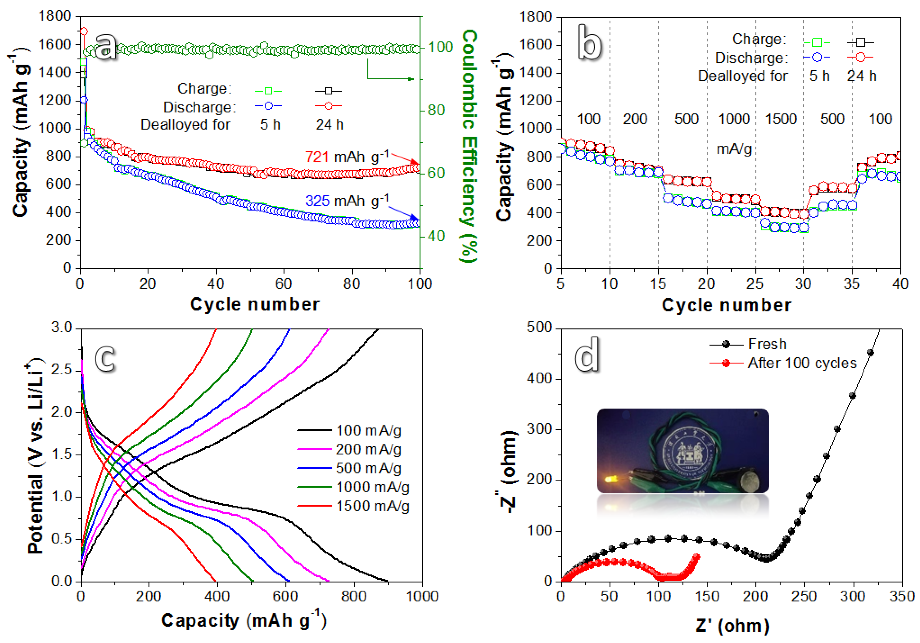
| Dual-network porous Fe3O4/NiO | 100 | 100 | 721 | This work |
© 2020 by the authors. Licensee MDPI, Basel, Switzerland. This article is an open access article distributed under the terms and conditions of the Creative Commons Attribution (CC BY) license (http://creativecommons.org/licenses/by/4.0/).
Share and Cite
Zhang, X.; Liu, X.; Zhou, J.; Qin, C.; Wang, Z. Improving the Cycling Stability of Fe3O4/NiO Anode for Lithium Ion Battery by Constructing Novel Bimodal Nanoporous Urchin Network. Nanomaterials 2020, 10, 1890. https://doi.org/10.3390/nano10091890
Zhang X, Liu X, Zhou J, Qin C, Wang Z. Improving the Cycling Stability of Fe3O4/NiO Anode for Lithium Ion Battery by Constructing Novel Bimodal Nanoporous Urchin Network. Nanomaterials. 2020; 10(9):1890. https://doi.org/10.3390/nano10091890
Chicago/Turabian StyleZhang, Xiaomin, Xiaoli Liu, Jun Zhou, Chunling Qin, and Zhifeng Wang. 2020. "Improving the Cycling Stability of Fe3O4/NiO Anode for Lithium Ion Battery by Constructing Novel Bimodal Nanoporous Urchin Network" Nanomaterials 10, no. 9: 1890. https://doi.org/10.3390/nano10091890
APA StyleZhang, X., Liu, X., Zhou, J., Qin, C., & Wang, Z. (2020). Improving the Cycling Stability of Fe3O4/NiO Anode for Lithium Ion Battery by Constructing Novel Bimodal Nanoporous Urchin Network. Nanomaterials, 10(9), 1890. https://doi.org/10.3390/nano10091890


