Article

Micromagnetic Simulations of Chaotic Ferromagnetic Nanofiber Networks

1
Institute of Physics—Center for Science and Education, Silesian University of Technology, 44-100 Gliwice, Poland
2
Faculty of Engineering and Mathematics, Bielefeld University of Applied Sciences, 33619 Bielefeld, Germany
*
Author to whom correspondence should be addressed.
Nanomaterials 2020, 10(4), 738; https://doi.org/10.3390/nano10040738
Submission received: 26 March 2020 / Revised: 4 April 2020 / Accepted: 8 April 2020 / Published: 12 April 2020
(This article belongs to the Special Issue Magnetism of Metal and Metal-Oxide Nanoparticles)

Abstract

:
Electrospinning can be used to create nanofibers with diameters of typically a few tens to a few hundred nanometers. While pure polymers are often electrospun, it is also possible to use polymer blends or to include nanoparticles. In this way, e.g., magnetic nanofiber networks can be created with a certain diameter distribution, random fiber orientations, and random crossing positions and angles. Here we present for the first time micromagnetic simulations of small parts of stochastically oriented nanofiber networks. Magnetization reversal mechanisms are investigated for different local spatial distributions; mutual influences of neighboring magnetic fibers due to dipolar interactions are depicted. This study serves as a base for the possible use of such stochastic nanofiber networks in the research area of neuro-inspired materials.

1. Introduction

Microscopically non-ordered systems of ferromagnetic fibers belong to the recently intensively investigated materials due to the accessible technologies of sample preparation. One of the dominating methods to produce such samples is electrospinning from liquid solutions in the presence of high electric fields. Electrospinning can be used to create nanofiber mats from diverse man-made polymers [1,2], biopolymers [3,4] or blends of polymers with non-soluble materials [5,6]. In this way, it is also possible to prepare magnetic materials by adding magnetic nanoparticles to the spinning solution [7,8].
Such magnetic nanofibers show interesting static and dynamic properties that have been investigated in theory and in experiments by many groups [9,10,11]. The influence of the bending radius of such nanofibers was found to be especially crucial [12,13,14] for the magnetization reversal dynamics. Besides basic research, nanofiber networks may be used in future in neuromorphic computing since they combine data transport paths with stochastically distributed overlapping and crossing points [13].
Until now, however, no simulations of stochastically ordered nanofiber networks or parts of them, comprising arbitrary crossing positions and angles, can be found in the scientific literature. Here we give a first overview of possible magnetization reversal processes and the influence of crossing point geometries as well as fiber cross-sections [15,16]. We discuss the impact of the numbers of crossing points and of the distance between neighboring nanofibers on coercive fields and magnetization reversal scenarios. It should be mentioned that the nanofibers under investigation here have even surfaces, as found experimentally for pure electrospinning [17,18]; opposite to fibers prepared by a new microwave plasma-based method that were recently reported, and which showed a hierarchical, complex fractal structure [19]. Rougher surfaces and possibly even fractal structures could be created by combining the electrospinning technique with additional electrospraying used in this study [20], or by carbonization or calcination of polymer/magnetic nanoparticle nanofibers, prepared by electrospinning [21,22,23]. Such technologies may lead to even more interesting magnetization reversal processes, e.g., featuring a domain wall trapping due to surface notches [24,25,26].

2. Simulations

Micromagnetic simulations were carried out using two solvers. Firstly, they were based on OOMMF (Object Oriented MicroMagnetic Framework) [27] to simulate iron (Fe). Fe was chosen since our former simulation revealed interesting magnetization reversal processes in Fe nanodots [28] as well as nanofibers [13]; typical literature values were chosen as material parameters: magnetization at saturation MS = 1700 × 103 A/m, exchange constant A = 21 × 10−12 J/m, magneto-crystalline anisotropy constant K1 = 48 × 103 J/m3. The Gilbert damping constant was set to α = 0.5 (equivalent to a quasi-static case).
Two different geometries of stochastic fiber crossing points were arbitrarily chosen to mimic the SEM (scanning electron microscopy) images of real electrospun magnetic nanofiber mats and were simulated for diverse magnetic field orientations. Sample NF1 (as defined in Figure 1) corresponds to a crossing area; in sample NF2 the horizontal branches were cut so that only a single nanofiber of slightly irregular diameter remained. Besides, the thicknesses of both nanofibers were varied between round and strongly elliptical cross-sections. The latter can be produced by pressing the electrospun nanofiber mats under different conditions.
Second, the micromagnetic solver MagPar was used [30], which dynamically integrates the Landau-Lifshitz-Gilbert equation of motion and is better suited for magnetic objects in freely defined positions in a given space. Simulations were performed on sets of 10 permalloy cylinders with a length of 200 nm and a diameter of 20 nm and varying degrees of rotation freedom. For this, spherical coordinates were selected using the following expressions:
θ = r a n d ( 90 o Δ θ , 90 o + Δ θ ) ,
and
φ = r a n d ( 0 + Δ φ ) ,
where the spherical coordinates θ and φ are selected randomly from the defined ranges, and Δ θ and Δ φ are varied between 0° and 90° in steps of 10°. In this way, an evolution from a fully 2D set of fibers into a 3D chaotic set is performed, thus showing the influence of fiber orientation on the overall magnetization reversal process. The simulation parameters were: exchange constant A = 1.05 10−11 J/m, magnetic polarization at saturation Js = 1 T, and the Gilbert damping constant α = 0.01.

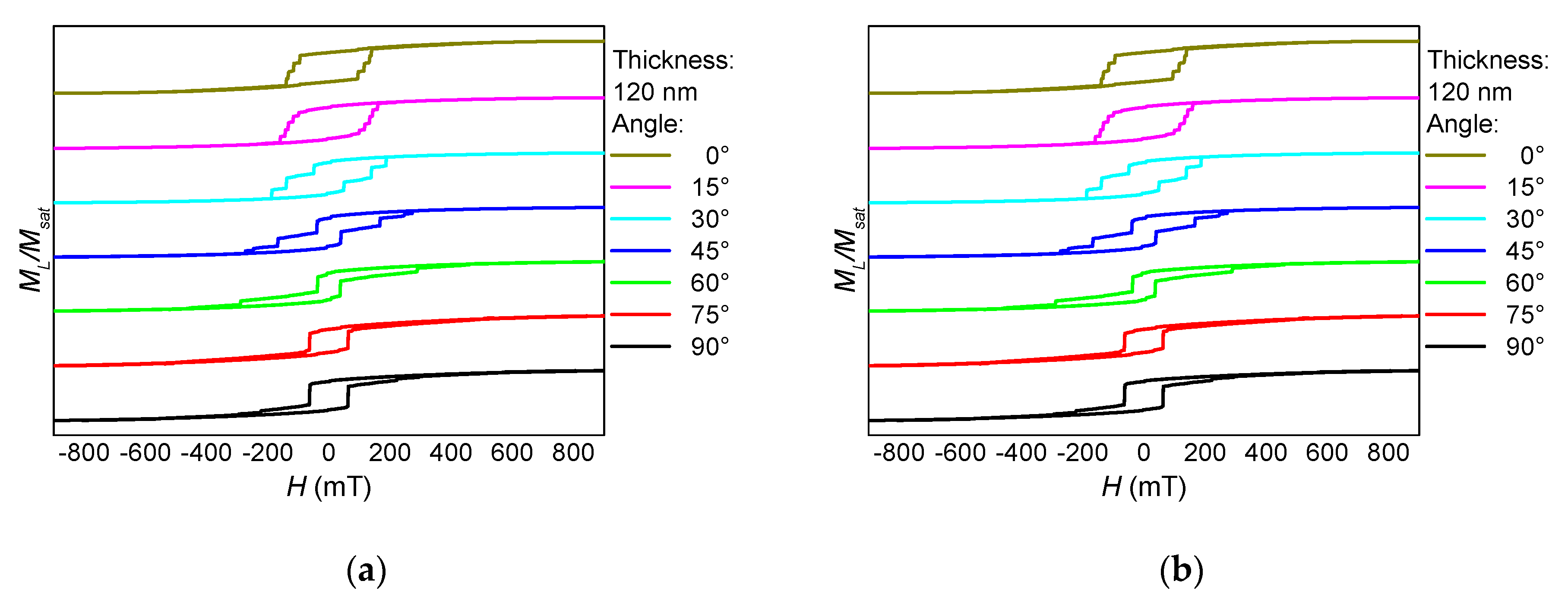
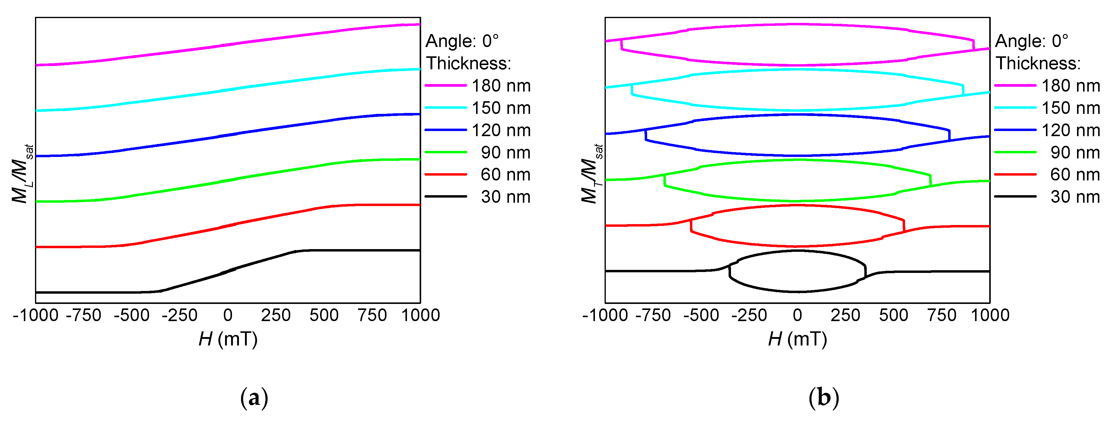
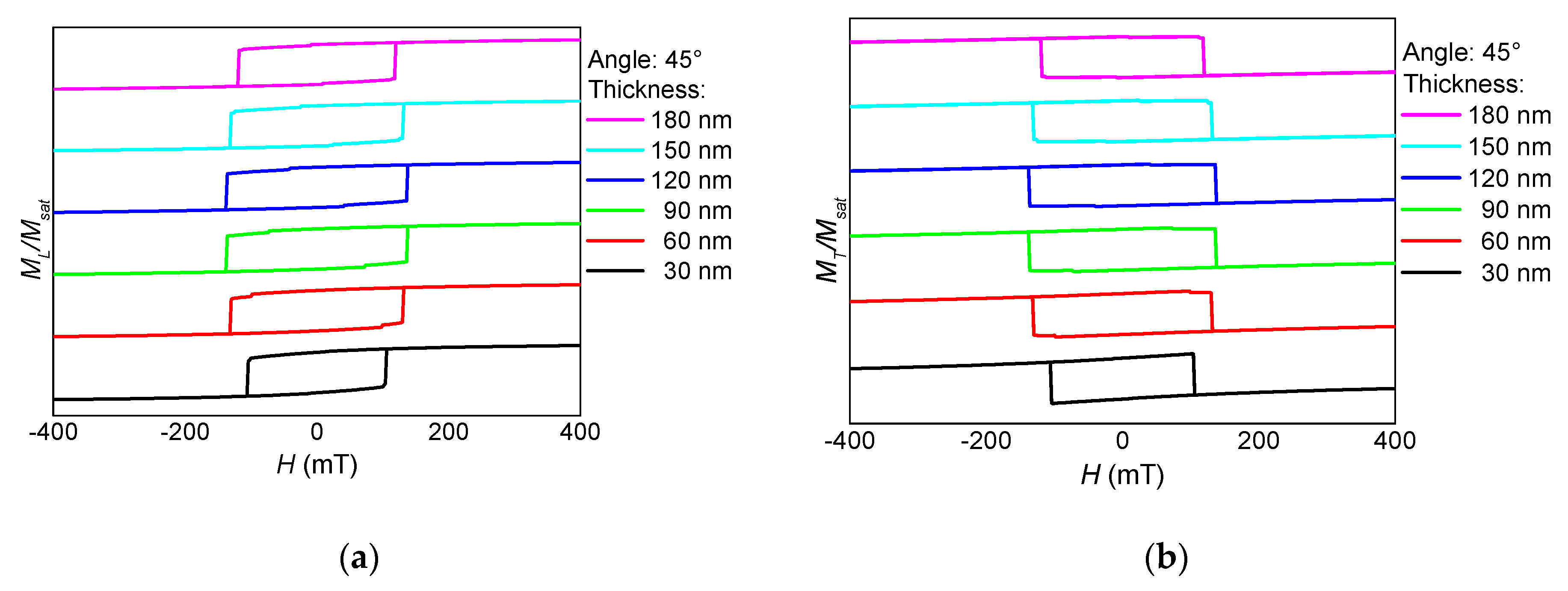
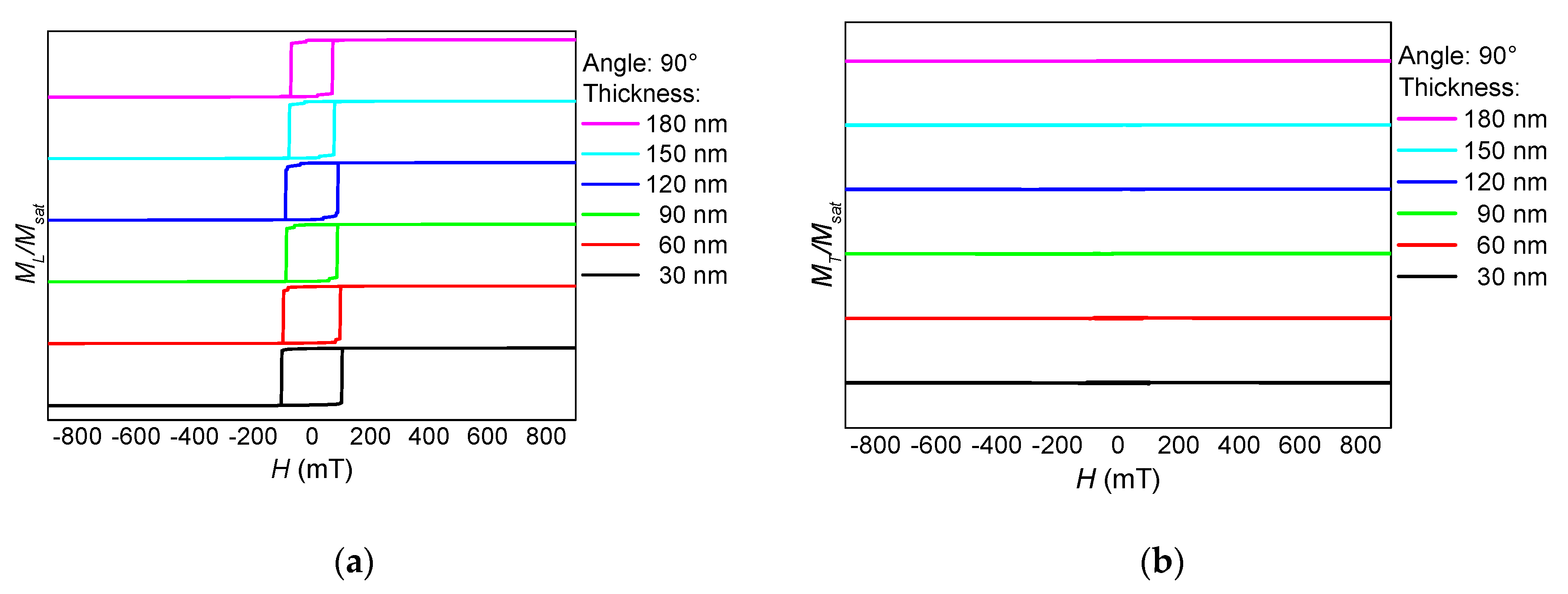
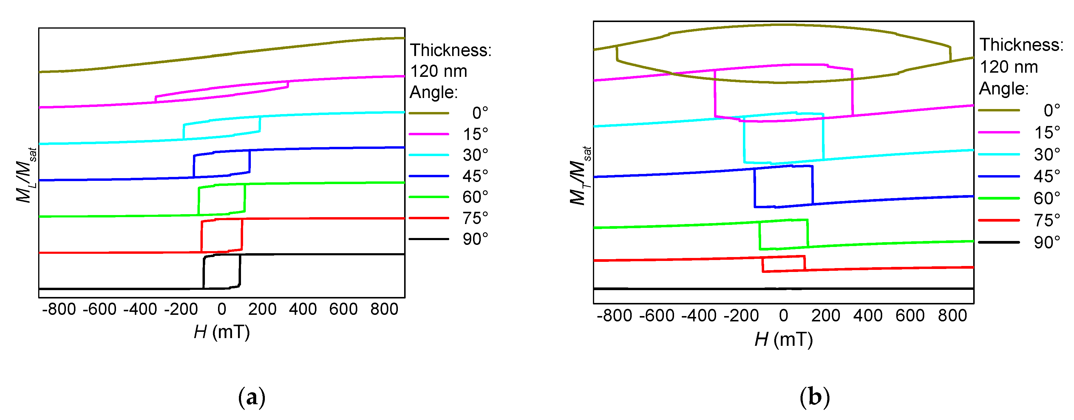
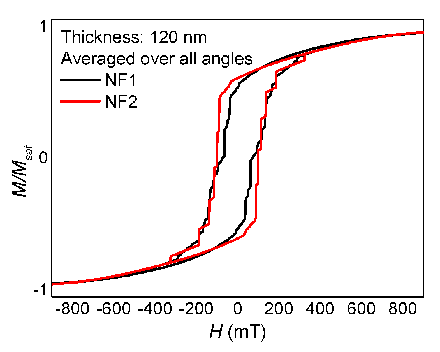
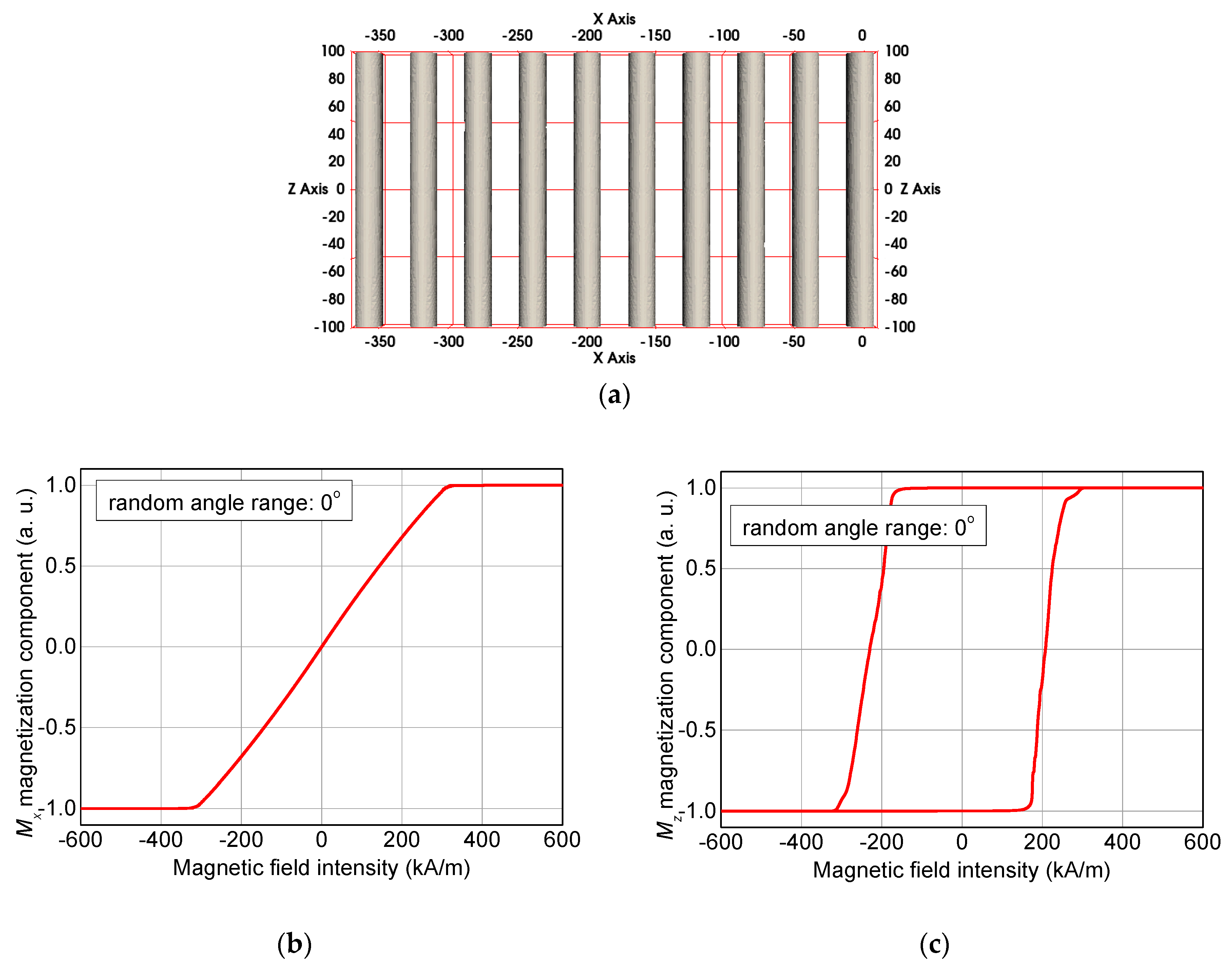
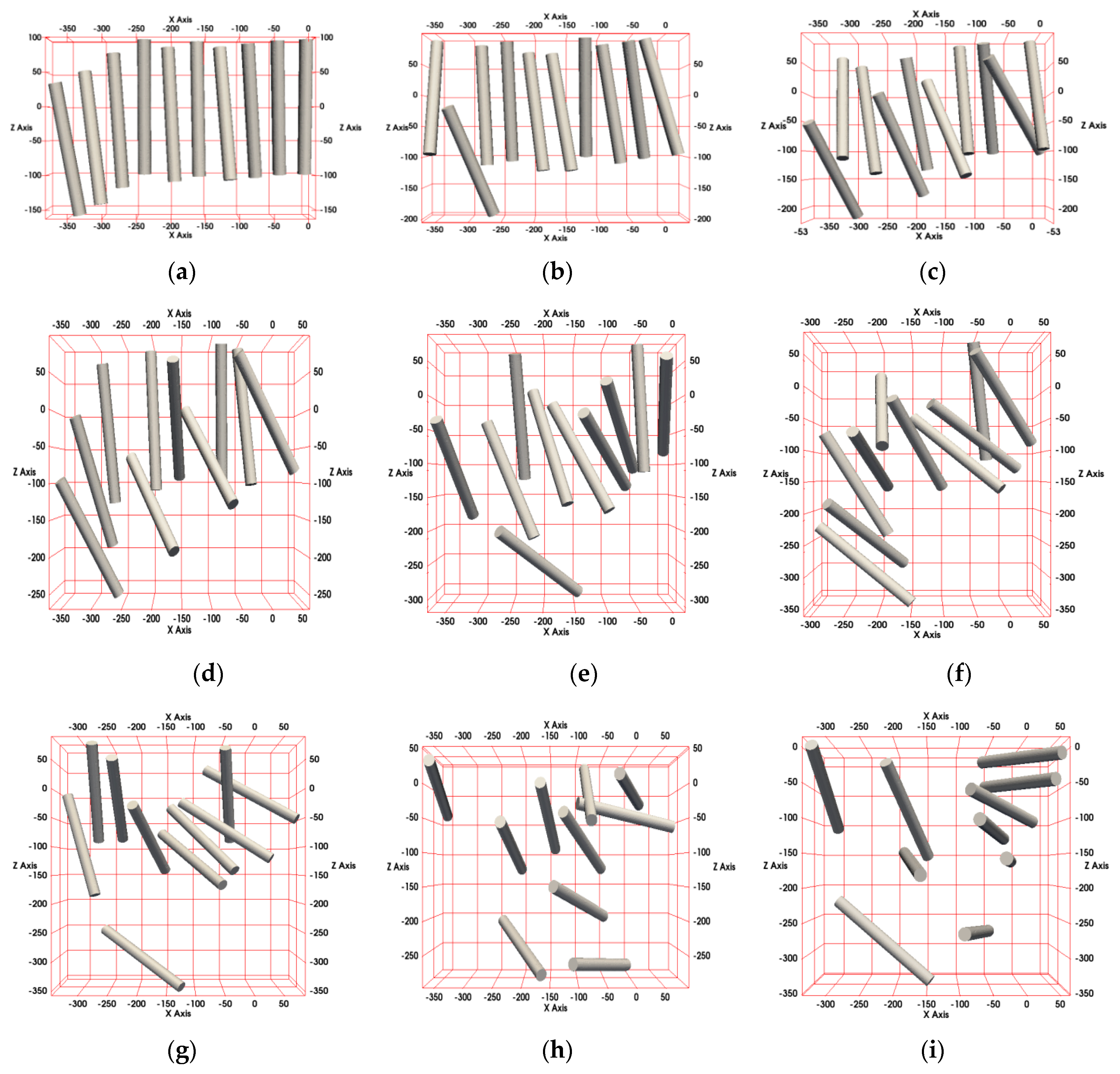
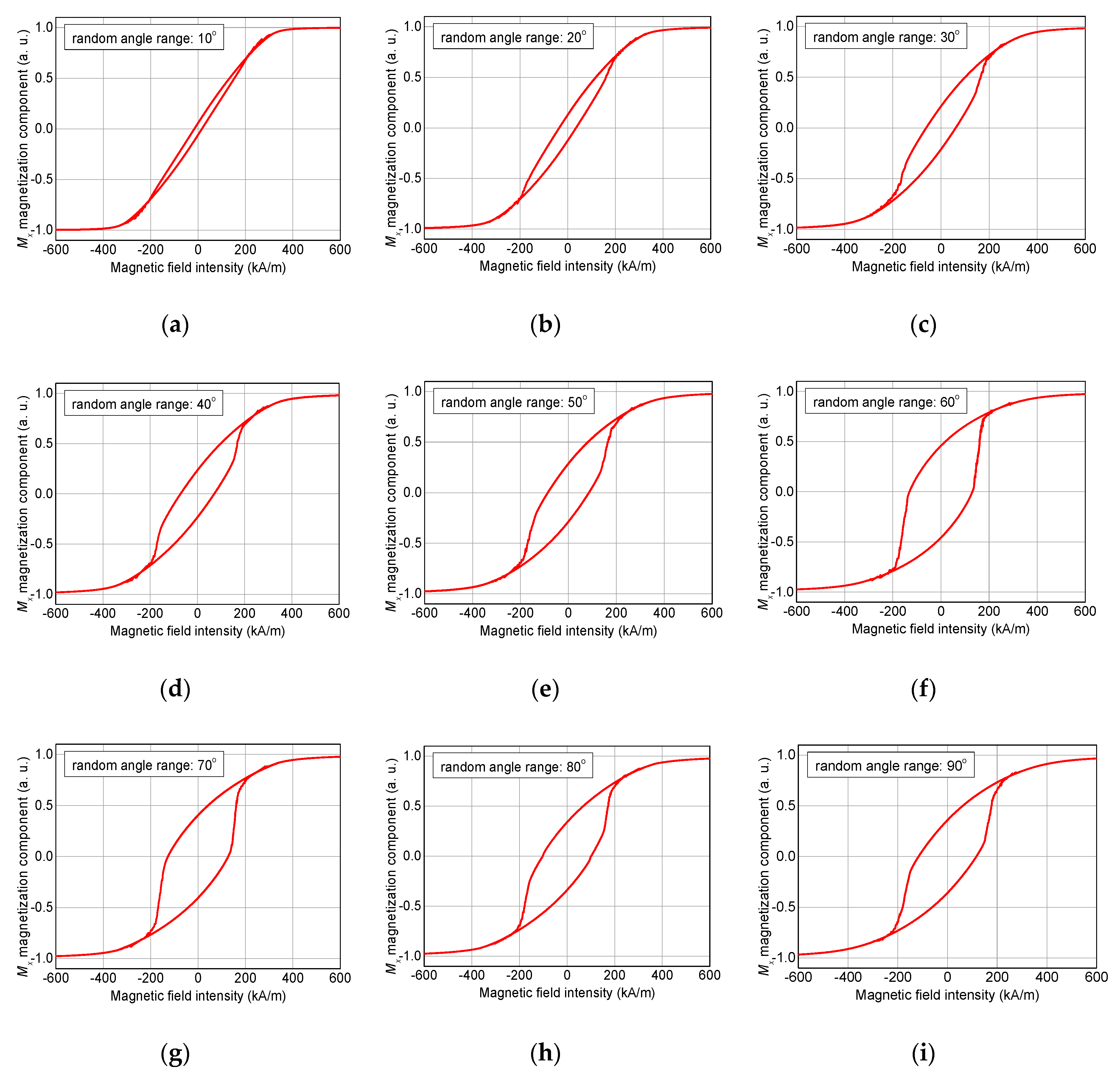
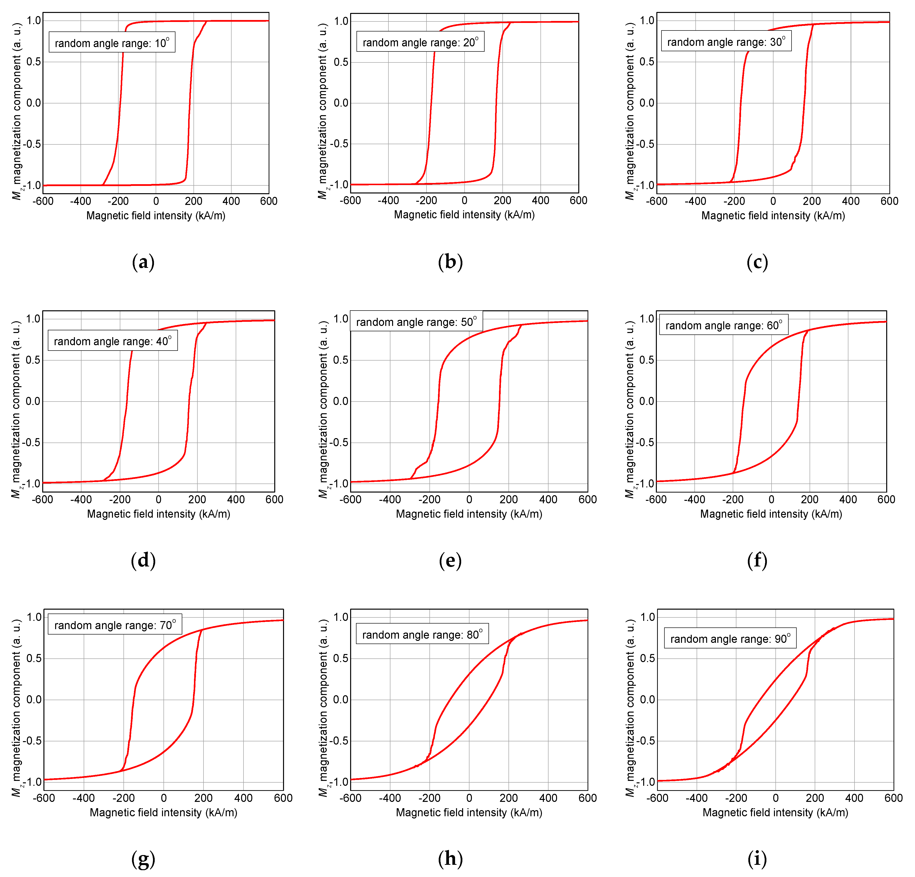
3. Results and Discussion

Figure 1 depicts a magnetization reversal process of an arbitrarily chosen part of a magnetic nanofiber mat (sample NF1). It is clearly visible that due to the shape anisotropy, magnetization reversal occurs firstly in the thicker “vertical” fiber, while larger external magnetic fields are necessary to switch magnetization in the thinner “horizontal” fibers as well.
These separate magnetization reversal processes can also be recognized in the hysteresis loops, as depicted in Figure 2, Figure 3 and Figure 4. Here, the influence of the fiber thickness is also visible, underlining the possibility to influence the magnetic properties of such nanofiber networks by mechanical treatment after the electrospinning process. While the coercive fields are always in a similar field region, the width of the steps along the slopes of the loops differs strongly with the angular orientation and the nanofiber thickness. Such steps are correlated with irreversible magnetization reversal processes, such as nucleation and disappearance of domain walls [13,14,28], which can possibly be used for data storage in quaternary or higher-order memory devices.
The angular dependence of longitudinal and transverse hysteresis loops is depicted in Figure 5. Especially the transverse loops indicate a broad range of magnetization reversal processes, always connected with a number of steps along the hysteresis loops and thus with domain wall processes. This corresponds to the exemplary process in Figure 1, showing that the horizontal parts of this part of a nanofiber mat switch at different external magnetic fields, depending on their angular orientation and cross-section area.
It should be mentioned that all longitudinal and transverse hysteresis loops visible here and in the previous figures are not unusual for magnetic nanostructures—especially nanoparticles with crossed or bent wires or “walls”—investigated under different angles with respect to the external magnetic field [13,14,31]. The difference between the magnetic nano-structure simulated here and the common regular nanoparticles is that the “branches” and the “main cylinder” here differ in diameter, the angles between fiber parts at the intersections are arbitrary, as well as the bending radii; opposite to lithographically structured samples in which deviations from a defined geometry are undesired. This leads, e.g., to a missing fourfold symmetry (Figure 5) and thus to much more complicated angular dependencies of the longitudinal and transverse hysteresis loops as well as the coercive fields and magnetization reversal orientations (clockwise or counter-clockwise), as given by the signs of the transverse magnetization peaks.
After cutting the horizontal branches, the new sample NF2 shows a completely different behavior. As visible in Figure 6, Figure 7 and Figure 8 from the absence of steps, no domain wall processes are involved here in magnetization reversal. Instead, the 0° orientation shows the typical behavior of the magnetic field along a hard axis, with the magnetization relaxing with reduced magnetic field, as visible in the transverse o-shaped loops, and switching only at high external magnetic fields.
For 45° (Figure 7), longitudinal and transverse hysteresis loops look more like the usual Stoner-Wohlfarth-like coherent rotation of the magnetization [32], while for 90° (Figure 8), the magnetization switches without large transverse signals, i.e., without rotating out of the orientation preferred by the external magnetic field as well as the shape anisotropy.
The rotation of the sample NF2 at an average thickness of 120 nm again results in a strong angular dependence of the shape of longitudinal and transverse hysteresis loops as well as of the coercive fields (Figure 9). Nevertheless, these hysteresis loops look quite different from those of sample NF1, depicted in Figure 5. Here, a clear transition from a hard axis near 0° to an easy axis near 90° is visible, while this general behavior of sample NF1 was strongly superimposed by the magnetization reversal in the “horizontal branches”, making magnetization reversal processes much more interesting in the branched sample and also strongly modifying coercive fields as well as, for data storage applications more importantly, saturation fields, i.e., external magnetic fields which were sufficient to reach full magnetization reversal.
This leads to the question whether the shape of a hysteresis loop, measured macroscopically by averaging over all possible angular orientations, may be used to investigate how many crossing points there are in a given electrospun sample. Figure 10 thus compares hysteresis loops averaged over the angles presented here for the samples NF1 (with branches) and NF2 (without branches). While the coercive fields are quite similar in both cases, the shapes of the loops differ nevertheless, indicating that a macroscopic measurement of the longitudinal magnetization component may indeed enable distinguishing between samples with many branches and with nearly no nodes. The numbers and dimensions of contact points can be tailored experimentally by stabilizing the nanofiber mats [33], thus this idea can be examined practically in the near future.
Finally, the question arises how strongly neighboring fibers with or without branches (NF1 or NF2) will influence each other, depending on the distance between them. Figure 11 shows hysteresis loops for different situations, as depicted in the insets.
Adding a second nanofiber NF2 to the first one (Figure 11a), the resulting hysteresis loop is similar to the original measurement (added as light grey line). Nevertheless, there is already a step in the slope visible. Adding a third nanofiber (Figure 11b) results in an additional step, corresponding to three different external magnetic fields when the single fibers are reversed. Five nanofibers result correspondingly in a hysteresis loop with five steps, which in addition becomes much broader, i.e., magnetization reversal starts at smaller negative magnetic fields and ends at larger negative fields than in the case of the single nanofiber NF2 (Figure 11c). It should be mentioned that the order in which the fibers switch magnetization depends not only on their position, but also on the (arbitrary) orientation of the anisotropy axes in each single cell of the simulated model, corresponding to the preparation by a common sputter process. Thus, such a system is not perfectly suited for real data storage systems.
Figure 11d shows a comparison of the magnetization reversal processes of NF1 (light grey line) and a doubled version of NF1 (black line, confer inset). Here, the original branched fiber showed already four steps along the slope of the hysteresis loops, while the doubled NF1 system results in six steps of very different width and height. One can imagine that going on to extend the nanofiber network further will lead to more and more—and thus smaller and smaller—steps. This suggests changing from such macroscopic measurements and simulations to experimental and theoretical investigations of small areas, ideally of single fibers within the network, as it can be done, e.g., by magnetic force microscopy.
After investigating the influence of branches by OOMMF, the next simulations will show the impact of arbitrarily varying orientations of unbranched fibers, as performed by MagPar. Figure 12 defines the axes used here and gives a first idea of the magnetization components along the x-axis (Mx) and along the z-axis (Mz).
For the angle of 0° shown here, i.e., the non-random case of perfectly parallel fibers, the magnetization reversal for a field sweep along the x-axis shows the typical closed loop of a hard axis (Figure 12b), while sweeping the magnetization along the z-axis results in the usual shape of the hysteresis loop simulated along an easy axis.
The other simulated sets of fibers are depicted in Figure 13 for random angle ranges between 10° and 90°.
Figure 14 and Figure 15 show the magnetization reversal processes for external magnetic field sweeps along the x-axis (Figure 14) or along the z-axis (Figure 15), respectively.
For the hysteresis loops simulated along the x-axis, a tendency to larger coercive fields, i.e., broader hysteresis loops for larger random angle ranges is clearly visible. Nevertheless, a hysteresis loop similar to the one simulated along the soft axis, as shown in Figure 12c, is not reached. Instead, for random angle ranges of 80° or 90°, the shapes of the hysteresis loops do not differ strongly from those simulated for random angle ranges of 50° or 60°.
This is different for the field sweeps along the z-axis. Here, starting from typical easy axis loops for small random angle ranges, the coercive fields are still in a similar order of magnitude for simulations of random angle ranges of 40° to 60°, while the random angle ranges of 80° and 90° are similar to those simulated along the x-axis—which is obvious since for a random angle range of 90°, x- and z-axis are equivalent, and only the randomly chosen fiber orientations for the special case under simulation cause arbitrary differences.
This short overview depicts the strong influence of not only branching of fibers, but also the orientations of unbranched fibers with respect to neighboring ones and to an external magnetic field, on magnetization reversal processes and resulting hysteresis loops.

4. Conclusions

Magnetic iron nanofibers of varying diameters with and without branches were studied by micromagnetic simulations. In both cases, a strong dependence of longitudinal and transverse hysteresis loops on the orientation of the external magnetic field and the fiber thickness, which can be modified experimentally by mechanically pressing the nanofiber mats, was found.
Averaging over all angles under investigation, the branched fiber and the one without branches showed slightly different longitudinal hysteresis loops. Future experimental investigations are necessary to evaluate whether such magnetic examinations reveal a macroscopic measurement for the average numbers of nodes on the nanoscale.
The neighboring fibers were found to significantly influence the shape of hysteresis loops, offering a possible measure of the nanofiber density in a sample. This effect was even more pronounced for sets of nanofibers with angular orientations of growing randomness.
Future simulations and experiments will deal with magnetization reversal in larger-scale nanofiber networks as well as magnetization dynamics, especially the possibility of domain wall nucleation and propagation through nanofibers of different 3D orientation and along nodes between arbitrarily oriented nanofibers.

Author Contributions

conceptualization, all authors; methodology, T.B. and A.E.; validation, T.B. and A.E.; investigation, all authors; writing—original draft preparation, T.B. and A.E.; writing—review and editing, all authors. All authors have read and agreed to the published version of the manuscript.

Funding

This work was supported by Volkswagen Foundation grant “Adaptive Computing with Electrospun Nanofiber Networks” no. 93679. The APC is funded by the Open Access Publication Fund of Bielefeld University of Applied Sciences and the Deutsche Forschungsgemeinschaft (DFG, German Research Foundation) – 414001623.

Conflicts of Interest

The authors declare no conflict of interest. The funders had no role in the design of the study; in the collection, analyses, or interpretation of data; in the writing of the manuscript, or in the decision to publish the results.

References

  1. Pan, J.-F.; Liu, N.-H.; Sun, H.; Xu, F. Preparation and Characterization of Electrospun PLCL/Poloxamer Nanofibers and Dextran/Gelatin Hydrogels for Skin Tissue Engineering. PLOS ONE 2014, 9, e112885. [Google Scholar] [CrossRef] [PubMed] [Green Version]
  2. Grothe, T.; Wehlage, D.; Böhm, T.; Remche, A.; Ehrmann, A. Needleless Electrospinning of PAN Nanofibre Mats. Tekstilec 2017, 60, 290–295. [Google Scholar] [CrossRef]
  3. Maver, T.; Kurečič, M.; Smrke, D.M.; Kleinschek, K.S.; Maver, U. Electrospun nanofibrous CMC/PEO as a part of an effective pain-relieving wound dressing. J. Sol-Gel Sci. Technol. 2015, 79, 475–486. [Google Scholar] [CrossRef]
  4. Grimmelsmann, N.; Grothe, T.; Homburg, S.V.; Ehrmann, A. Electrospinning and stabilization of chitosan nanofiber mats. IOP Conf. Ser. Mater. Sci. Eng. 2017, 254, 102006. [Google Scholar] [CrossRef]
  5. Salalha, W.; Dror, Y.; Khalfin, R.L.; Cohen, Y.; Yarin, A.L.; Zussman, E. Single-Walled Carbon Nanotubes Embedded in Oriented Polymeric Nanofibers by Electrospinning. Langmuir 2004, 20, 9852–9855. [Google Scholar] [CrossRef]
  6. Lim, J.-M.; Moon, J.H.; Yi, G.-R.; Heo, C.-J.; Yang, S.-M. Fabrication of One-Dimensional Colloidal Assemblies from Electrospun Nanofibers. Langmuir 2006, 22, 3445–3449. [Google Scholar] [CrossRef]
  7. Na, K.-H.; Kim, W.-T.; Park, D.-C.; Shin, H.-G.; Lee, S.-H.; Park, J.; Song, T.-H.; Choi, W.-Y. Fabrication and characterization of the magnetic ferrite nanofibers by electrospinning process. Thin Solid Films 2018, 660, 358–364. [Google Scholar] [CrossRef]
  8. Döpke, C.; Grothe, T.; Steblinski, P.; Klöcker, M.; Sabantina, L.; Kosmalska, D.; Blachowicz, T.; Ehrmann, A. Magnetic Nanofiber Mats for Data Storage and Transfer. Nanomaterials 2019, 9, 92. [Google Scholar] [CrossRef] [Green Version]
  9. Ryu, K.-S.; Thomas, L.; Yang, S.-H.; Parkin, S.S.P. Current Induced Tilting of Domain Walls in High Velocity Motion along Perpendicularly Magnetized Micron-Sized Co/Ni/Co Racetracks. Appl. Phys. Express 2012, 5, 093006. [Google Scholar] [CrossRef]
  10. Yang, S.-H.; Ryu, K.-S.; Parkin, S. Domain-wall velocities of up to 750 m s−1 driven by exchange-coupling torque in synthetic antiferromagnets. Nat. Nanotechnol. 2015, 10, 221–226. [Google Scholar] [CrossRef]
  11. Alejos, O.; Raposo, V.; Sánchez-Tejerina, L.; Martínez, E. Efficient and controlled domain wall nucleation for magnetic shift registers. Sci. Rep. 2017, 7, 11909. [Google Scholar] [CrossRef] [PubMed] [Green Version]
  12. Garg, C.; Yang, S.-H.; Phung, T.; Pushp, A.; Parkin, S.S.P. Dramatic influence of curvature of nanowire on chiral domain wall velocity. Sci. Adv. 2017, 3, e1602804. [Google Scholar] [CrossRef] [PubMed] [Green Version]
  13. Blachowicz, T.; Ehrmann, A. Magnetization reversal in bent nanofibers of different cross sections. J. Appl. Phys. 2018, 124, 152112. [Google Scholar] [CrossRef] [Green Version]
  14. Kern, P.; Döpke, C.; Blachowicz, T.; Steblinski, P.; Ehrmann, A. Magnetization reversal in ferromagnetic Fibonacci nano-spirals. J. Magn. Magn. Mater. 2019, 484, 37–41. [Google Scholar] [CrossRef]
  15. Wang, Z.; Crandall, C.; Sahadevan, R.; Menkhaus, T.; Fong, H. Microfiltration performance of electrospun nanofiber membranes with varied fiber diameters and different membrane porosities and thicknesses. Polymer 2017, 114, 64–72. [Google Scholar] [CrossRef]
  16. Yalcinkaya, F.; Hruza, J. Effect of Laminating Pressure on Polymeric Multilayer Nanofibrous Membranes for Liquid Filtration. Nanomaterials 2018, 8, 272. [Google Scholar] [CrossRef] [Green Version]
  17. Tripathy, M.; Hota, G. Maghemite and Graphene Oxide Embedded Polyacrylonitrile Electrospun Nanofiber Matrix for Remediation of Arsenate Ions. ACS Appl. Polym. Mater. 2019, 2, 604–617. [Google Scholar] [CrossRef]
  18. Fokin, N.; Grothe, T.; Mamun, A.; Trabelsi, M.; Klöcker, M.; Sabantina, L.; Döpke, C.; Blachowicz, T.; Hütten, A.; Ehrmann, A. Magnetic Properties of Electrospun Magnetic Nanofiber Mats after Stabilization and Carbonization. Materials 2020, 13, 1552. [Google Scholar] [CrossRef] [Green Version]
  19. Bica, I.; Anitas, E.M.; Choi, H.; Sfirloaga, P. Microwave-assisted synthesis and characterization of iron oxide microfibers. J. Mater. Chem. C 2020. [Google Scholar] [CrossRef]
  20. Petropoulou, A.; Kralj, S.; Karagiorgis, X.; Savva, I.; Loizides, E.; Panagi, M.; Krasia-Christoforou, T.; Riziotis, C. Multifunctional Gas and pH Fluorescent Sensors Based on Cellulose Acetate Electrospun Fibers Decorated with Rhodamine B-Functionalised Core-Shell Ferrous Nanoparticles. Sci. Rep. 2020, 10, 1–14. [Google Scholar] [CrossRef]
  21. Wang, Y.J.; Sun, Y.; Zong, Y.; Zhu, T.G.; Zhang, L.X.; Li, X.H.; Xing, H.N.; Zheng, X.L. Carbon nanofibers supported by FeCo nanocrystals as difunctional magnetic/dielectric composites with broadband microwave absorption performance. J. Allows Compd. 2020, 824, 153980. [Google Scholar] [CrossRef]
  22. Pan, J.; Guo, H.; Wang, M.; Yang, H.; Hu, H.; Liu, P.; Zhu, H. Shape anisotropic Fe3O4 nanotubes for efficient microwave absorption. Nano Res. 2020, 13, 621–629. [Google Scholar] [CrossRef] [Green Version]
  23. Bhugra, V.S.; Williams, G.V.M.; Chong, S.V.; Nann, T. Electrospun, oriented, ferromagnetic Ni1-xFex nanofibers. Front. Chem. 2020, 8, 47. [Google Scholar] [CrossRef] [PubMed]
  24. Zambano, A.J.; Pratt, W.P. Detecting domain-wall trapping and motion at a constriction in narrow ferromagnetic wires using perpendicular-current giant magnetoresistance. Appl. Phys. Lett. 2004, 85, 1562. [Google Scholar] [CrossRef] [Green Version]
  25. Nasirpouri, F.; Peighambari-Sattari, S.-M.; Bran, C.; Palmero, E.M.; Eguiarte, E.B.; Vazquez, M.; Patsopoulos, A.; Kechrakos, D. Geometrically designed domain wall trap in tri-segmented nickel magnetic nanowires for spintronics devices. Sci. Rep. 2019, 9, 9010. [Google Scholar] [CrossRef]
  26. Abbas, N.; Wang, F.; Ren, H.; Liu, J.P.; Xia, W.; Du, J.; Zhao, G.; Zhang, J. Determination of interface layer effects on magnetic properties of nanocomposite magnets and exchange coupling between magnetic entities. Appl. Surf. Sci. 2019, 480, 454–462. [Google Scholar] [CrossRef]
  27. Donahue, M.J.; Porter, D.G. OOMMF User’s Guide, version 1.0; National Institute of Standards and Technology (NIST): Gaithersburg, MD, USA, 1999. [Google Scholar]
  28. Ehrmann, A.; Blachowicz, T. Vortex and double-vortex nucleation during magnetization reversal in Fe nanodots of different dimensions. J. Magn. Magn. Mater. 2019, 475, 727–733. [Google Scholar] [CrossRef]
  29. Blachowicz, T.; Döpke, C.; Ehrmann, A. Micromagnetic Simulations of Electrospun Nanofiber Networks; Works of the Institute of Engineering Materials and Biomedical Materials, Silesian University of Technology: Gliwice, Poland, 2019. [Google Scholar]
  30. Scholz, W.; Fidler, J.; Schrefl, T.; Suess, D.; Dittrich, R.; Forster, H.; Tsiantos, V. Scalable parallel micromagnetic solvers for magnetic nanostructures. Comput. Mater. Sci. 2003, 28, 366–383. [Google Scholar] [CrossRef]
  31. Blachowicz, T.; Ehrmann, A. Fourfold nanosystems for quaternary storage devices. J. Appl. Phys. 2011, 110, 73911. [Google Scholar] [CrossRef] [Green Version]
  32. Stoner, E.C.; Wohlfarth, E.P. A mechanism of magnetic hysteresis in heterogeneous alloys. Philos. Trans. R. Soc. London. Ser. A Math. Phys. Sci. 1948, 240, 599–642. [Google Scholar] [CrossRef]
  33. Sabantina, L.; Rodríguez-Cano, M.Á.; Klöcker, M.; Mateos, F.J.G.; Hidalgo, J.J.T.; Mamun, A.; Beermann, F.; Schwakenberg, M.; Voigt, A.-L.; Rodríguez-Mirasol, J.; et al. Fixing PAN Nanofiber Mats during Stabilization for Carbonization and Creating Novel Metal/Carbon Composites. Polymers 2018, 10, 735. [Google Scholar] [CrossRef] [PubMed] [Green Version]
Figure 1. Magnetization reversal process in sample NF1 for an external magnetic field along 45° from “lower left” to “upper right” orientation. From Blachowicz et al. [29].
Nanomaterials 10 00738 g001
Figure 2. Thickness dependence of (a) the longitudinal and (b) the transverse hysteresis loops, simulated for sample NF1 under an angle of 0°.
Nanomaterials 10 00738 g002
Figure 3. Thickness dependence of (a) the longitudinal and (b) the transverse hysteresis loops, simulated for sample NF1 under an angle of 45° (see Figure 1).
Nanomaterials 10 00738 g003
Figure 4. Thickness dependence of (a) the longitudinal and (b) the transverse hysteresis loops, simulated for a sample NF1 under an angle of 90°.
Nanomaterials 10 00738 g004
Figure 5. Angle dependence of (a) the longitudinal and (b) the transverse hysteresis loops, simulated for sample NF1 with a thickness of 120 nm.
Nanomaterials 10 00738 g005
Figure 6. Thickness dependence of (a) the longitudinal and (b) the transverse hysteresis loops, simulated for sample NF2 under an angle of 0°.
Nanomaterials 10 00738 g006
Figure 7. Thickness dependence of (a) the longitudinal and (b) the transverse hysteresis loops, simulated for sample NF2 under an angle of 45°.
Nanomaterials 10 00738 g007
Figure 8. Thickness dependence of (a) the longitudinal and (b) the transverse hysteresis loops, simulated for sample NF2 under an angle of 90°.
Nanomaterials 10 00738 g008
Figure 9. Angle dependence of (a) the longitudinal and (b) the transverse hysteresis loops, simulated for sample NF2 with a thickness of 120 nm.
Nanomaterials 10 00738 g009
Figure 10. Angle dependence of the longitudinal and transverse hysteresis loops simulated for sample NF2 with a thickness of 120 nm.
Nanomaterials 10 00738 g010
Figure 11. Influence of neighboring fibers in different distances on the magnetization reversal process, simulated for an angle of 45° and a thickness of 120 nm. (a) two neighboring fibers NF2, (b) three neighboring fibers NF2, (c) five neighboring fibers NF2, and (d) two adjacent fibers NF1.
Nanomaterials 10 00738 g011
Figure 12. (a) Definition of the axes, magnetization components, (b) Mx, and (c) Mz in the non-random case of 0° possible deviation of the fiber orientation from the z-orientation.
Nanomaterials 10 00738 g012
Figure 13. Fiber orientations used in the simulations for random angle ranges, depicted in steps of 10°: (a) 10°, (b) 20°, (c) 30°, (d) 40°, (e) 50°, (f) 60°, (g) 70°, (h) 80°, and (i) 90°.
Nanomaterials 10 00738 g013
Figure 14. Hysteresis loops, simulated for an external magnetic field sweep along the x-axis and random angle ranges, depicted in steps of 10°: (a) 10°, (b) 20°, (c) 30°, (d) 40°, (e) 50°, (f) 60°, (g) 70°, (h) 80°, and (i) 90°.
Nanomaterials 10 00738 g014
Figure 15. Hysteresis loops, simulated for an external magnetic field sweep along the z-axis and random angle ranges, depicted in steps of 10°: (a) 10°, (b) 20°, (c) 30°, (d) 40°, (e) 50°, (f) 60°, (g) 70°, (h) 80°, and (i) 90°.
Nanomaterials 10 00738 g015

