Article

Microstructure-Induced Anisotropic Optical Properties of YF3 Columnar Thin Films Prepared by Glancing Angle Deposition

Department of Optical Science and Engineering, Key Laboratory of Micro and Nano Photonic Structures, Ministry of Education, Shanghai Engineering Research Center of Ultra-Precision Optical Manufacturing, Fudan University, Shanghai 200433, China
*
Author to whom correspondence should be addressed.
Nanomaterials 2020, 10(12), 2413; https://doi.org/10.3390/nano10122413
Submission received: 9 November 2020 / Revised: 30 November 2020 / Accepted: 30 November 2020 / Published: 3 December 2020
(This article belongs to the Special Issue Nanomaterials and Nanotechnology in Experimental Photonics)

Abstract

:
Yttrium fluoride (YF3) columnar thin films (CTFs) were fabricated by electron beam evaporation with the glancing angle deposition method. The microstructures and optical properties of YF3 CTFs were studied systematically. The YF3 films grown at different deposition angles are all amorphous. As the deposition angle increases, the columns in YF3 CTFs become increasingly separated and inclined, and the volume fraction of YF3 decreases, resulting in lower refractive indices. This phenomenon is attributed to the self-shadowing effect and limited adatom diffusion. The YF3 CTFs are optically biaxial anisotropic with the long axis (c-axis) parallel to the columns, the short axis (b-axis) perpendicular to the columns, and the other axis (a-axis) parallel to the film interface. The principal refractive index along the b-axis for the 82°-deposited sample is approximately 1.233 at 550 nm. For the 78°-deposited sample, the differences of principal refractive indices between the c-axis and the b-axis and between the a-axis and the b-axis reach the maximum 0.056 and 0.029, respectively. The differences of principal refractive indices were affected by both the deposition angle and the volume fraction of YF3.

1. Introduction

Microstructure materials have attracted great interest because of their high potential in a wide range of fields, such as electronics, photonics, magnetism, biomedicine, and chemistry [1]. Glancing angle deposition (GLAD) is an effective method for preparing variable Zone 1 columnar microstructures, which are defined as the structures of film material with a melting point three times higher than the substrate temperature [2,3]. By controlling the substrate tilt in multiple rotational ways, various columnar microstructures can be prepared by the GLAD method, such as columnar, spiral, c-shape, and z-shape [4]. The microstructure and the optical properties of the films fabricated by the GLAD method depend on the self-shadowing effect and the formation of columnar grains, leading to applications in optics, energy, electrocatalysts, electrochromism, thermochromism, etc. [5,6,7,8,9,10,11]. In addition, these highly oriented films with strong optical anisotropy have been used in specific applications, such as optical retardation plates, birefringent omnidirectional reflectors, and three-dimensional photonic crystals [12,13,14,15,16].
As a common and important fluoride compound, yttrium fluoride (YF3) has been widely used as nano-particles with efficient multicolor photoluminescence, high reflectors, thin-film interference filters, substitutes for radioactive ThF4, and anti-reflection coatings with other optical films ranging from the near-UV to IR [17,18,19,20,21,22,23]. These functions are available based on the nature of YF3, with low refractive index and low absorption, excellent transmittance from UV to IR, high hardness, and the desirable ability to match with other multilayer materials [19]. However, studies on the microstructure and the microstructure-induced anisotropic optical properties of YF3 columnar thin films (CTFs) fabricated by the GLAD technique are still limited. In this work, YF3 CTFs with various inclined angles were prepared by the GLAD technique, and their microstructures and anisotropic optical properties induced by the microstructures were systematically studied. The structure of prepared YF3 CTFs was characterized by X-ray diffraction (XRD). The surface and cross-sectional morphology of the YF3 CTFs were viewed by field-emission scanning electron microscopy (FE-SEM). Mueller matrix ellipsometry (MME), a powerful non-destructive and sensitive tool to study CTFs with high optical data precision, was employed to analyze the anisotropic optical properties of fabricated YF3 CTFs [24,25].

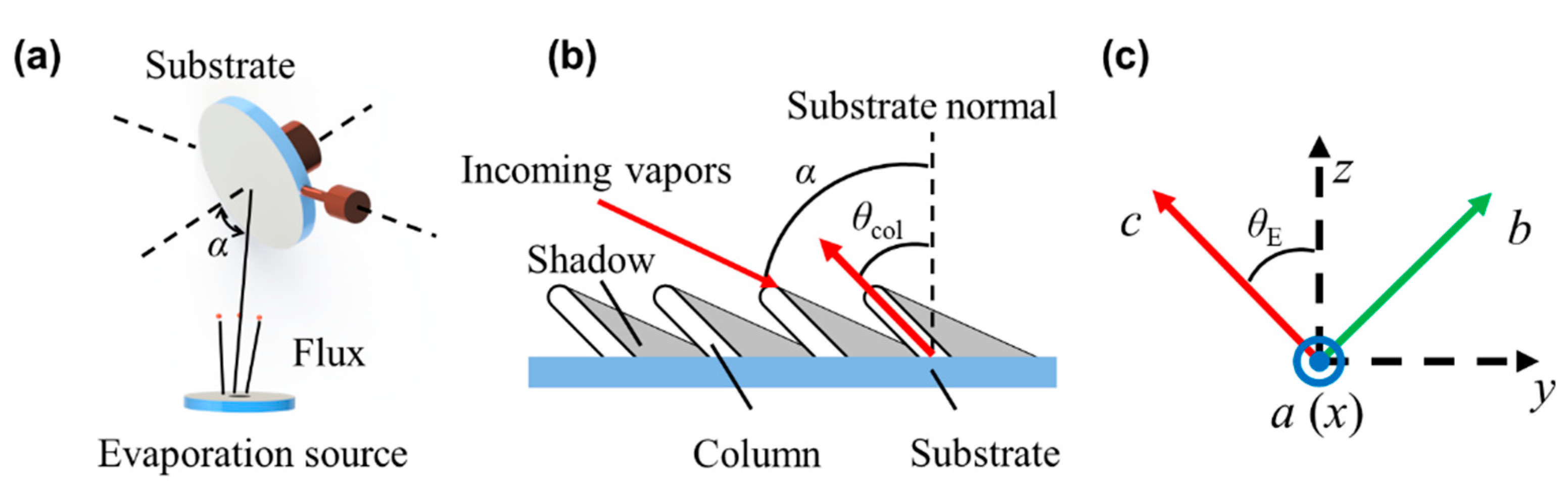
2. Theory and Optical Modeling

As shown in Figure 1a, the GLAD technique is applied to fabricate thin films on a substrate with an obliquely incident angle α of the vapor flux. The randomly deposited particles at the initial stage of deposition cause nuclei to be distributed over the surface, resulting in the ballistic shadowing of the surrounding regions. The limited surface mobility of adatoms prevents growth in the shadowed regions, thereby restricting further growth to the tops of the nuclei, which develop into tilted columnar structures [26]. Then, the isolated columns grow oriented toward the particle flow source, forming an inclined column angle θcol between the substrate surface normal and the column direction, as shown in Figure 1b.
The highly oriented structure of the inclined columns induces optical anisotropy [6]. In this case, the orthogonal electric field components are coupled due to the columnar structure and the porosity. Thus, an MME measurement is required to fully characterize the polarization-dependent optical response of anisotropic films. In the MME measurement, the sample is represented by a 4 × 4 Mueller matrix M, describing the effect on the light with Stokes vector [27]
S o u t = M   S i n ,
where Sin and Sout represent the Stokes vector of incident light and emerging light, respectively.
In the laboratory Cartesian coordinates (x, y, z), the columnar film is described by the second-rank tensor ε, written as
ε = ( ε x x ε x y ε x z ε y x ε y y ε y z ε z x ε z y ε z z ) .
In this coordinate system, the y-axis is parallel to the projection direction of columns on the substrate and the z-axis is parallel to the normal of film surface. For mathematical convenience, the dielectric tensor can be expressed by the principal dielectric constants through coordinate transformation. As shown in Figure 1c, the (x, y, z) system was transformed into the principal coordinate system (a, b, c) through two Euler rotations (θE, ϕ). The inclination angle θE, defined as the rotation from the z-axis to the c-axis, was considered to be equal to the inclined column angle θcol. The azimuth orientation ϕ, defined as the rotation around the z-axis, was set to zero when the columns were parallel to the plane of incidence (y-z plane). After coordinate transformation, the dielectric tensor in the (a, b, c) system was expressed as
ε = ( ε x x ε x y ε x z ε y x ε y y ε y z ε z x ε z y ε z z ) = A T ( ε a 0 0 0 ε b 0 0 0 ε c ) A .

3. Experimental Details

3.1. Materials and Sample Preparation

The YF3 CTFs were prepared by electron beam evaporation in a vacuum using the GLAD method. Single-side polished crystal <100> n-type silicon (99.99% in purity) wafers with a thickness of 350 ± 20 μm and a size of 10 mm × 10 mm were used as substrates. Granular YF3 (99.99% in purity) was heated by an electron beam at a high voltage of 7.8 kV and deposited onto the silicon substrates located 60 cm away from the evaporation source at a deposition rate of 0.20−0.25 nm s−1. The deposition angles were 0°, 66°, 70°, 78°, and 82°, respectively. All depositions were performed at a substrate temperature of 300 K and an operating pressure of 7 × 10⁻⁵ Torr.

3.2. Characterizations

The structural characteristics of the YF3 films were investigated by XRD with Cu-Kα (λ = 0.154056 nm) radiation (Bruker D8 ADVANCE) in the scanning range of 10.0°−45.0° with a step of 0.02°. The surface morphology and the cross-section of the YF3 films were viewed by FE-SEM (Hitachi, S-4800 FE-SEM). The optical properties of the YF3 samples were characterized by a variable-angle Mueller matrix ellipsometer (RC2, J. A. Woollam), which worked in the reflection mode with a dual-rotating compensator configuration [24,28]. The 4 × 4 Mueller matrices were measured over a spectral range of 300−1650 nm (i.e., 4.1 to 0.75 eV) at two incident angles 65° and 75°, respectively. The azimuth of samples rotated from 0° to 360° at a 45° interval. The analysis was performed with the software CompleteEASE (J. A. Woollam) [28].

4. Results and Discussion

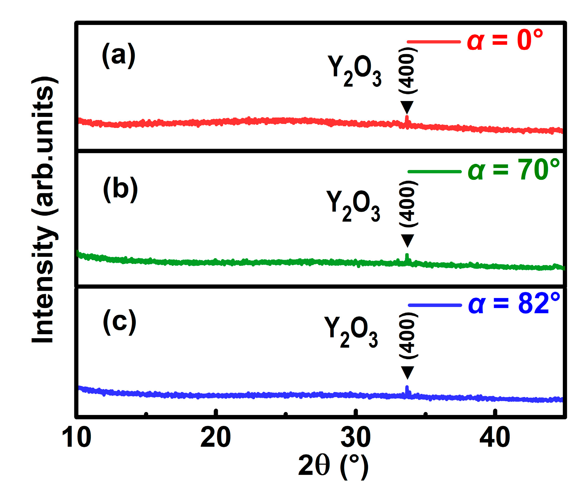
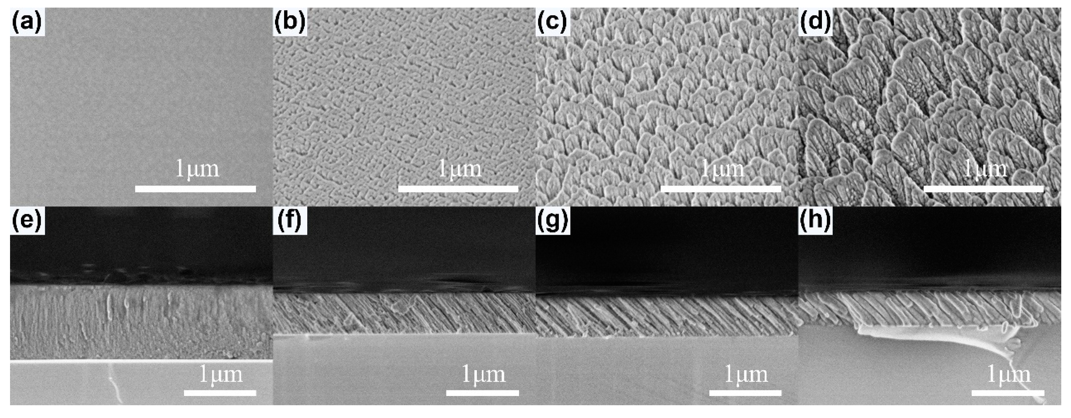
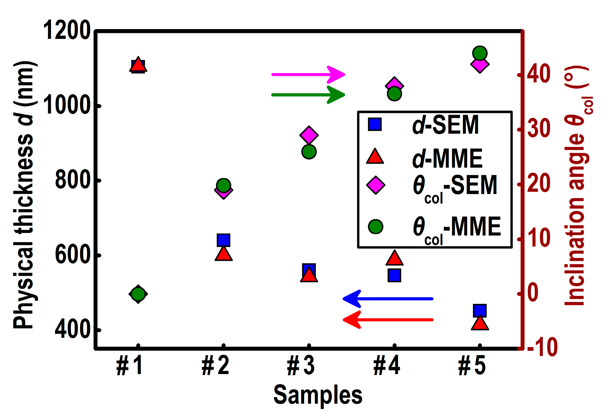
4.1. Microstructure of YF3 CTFs

Figure 2 presents the XRD patterns of as-deposited YF3 films grown on silicon substrates with deposition angles of 0°, 70°, and 82°, respectively. The (400) peak of cubic Y2O3 was observed at 2θ ≈ 33.7° in all the XRD spectra, indicating that Y2O3 was formed in all samples. No obvious diffraction peak corresponds to crystalline YF3, which means the intrinsic YF3 films are all amorphous. Since all YF3 samples were deposited at room temperature without annealing, this phenomenon can be attributed to the self-shadowing effect and limited adatom diffusion [6].
Figure 3a–d show the surface morphologies of the as-deposited YF3 films. The YF3 film grown at α = 0° is dense and shows a uniform morphology without voids. When α = 70°, the film becomes loose, with small pores appearing. In the case of α = 82°, the pores between columns become large in a rather loose film. The inclined columnar structures of the YF3 films are viewed in the cross-sectional SEM images (e–h) in Figure 3. The thickness d of YF3 films for each sample is 1104.6 nm (a, e), 560.2 nm (b, f), 546.5 nm (c, g), and 451.5 nm (d, h). The inclination angle θcol of YF3 films observed from the SEM images is 0° (a, e), 29° (b, f), 38° (c, g), and 42° (d, h). As the value of α increases, the columns are increasingly separated and inclined due to the self-shadowing effect, which prevails over the surface diffusion of adatoms and results in porous and low-density films.

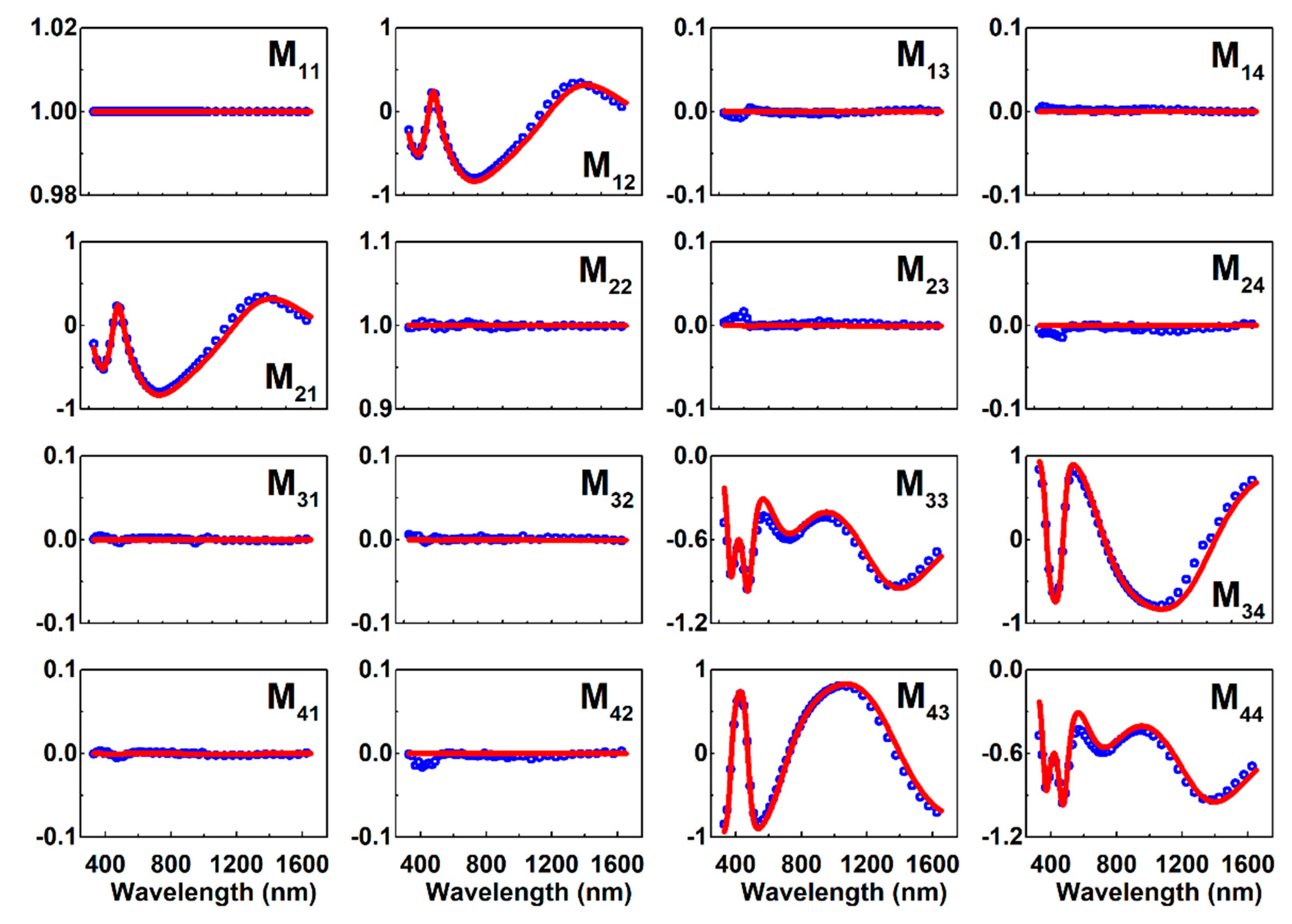
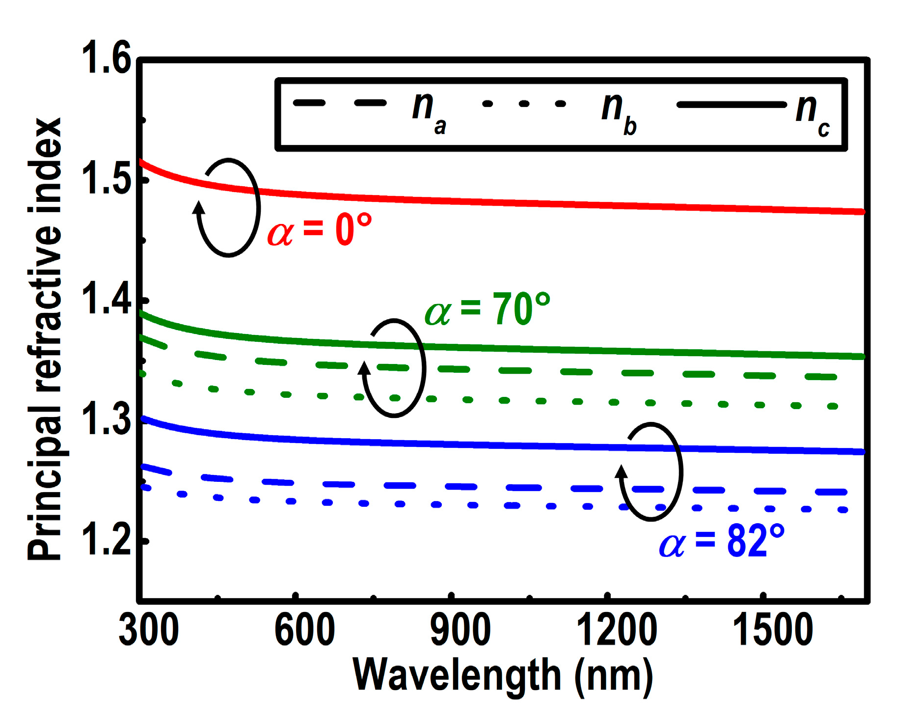
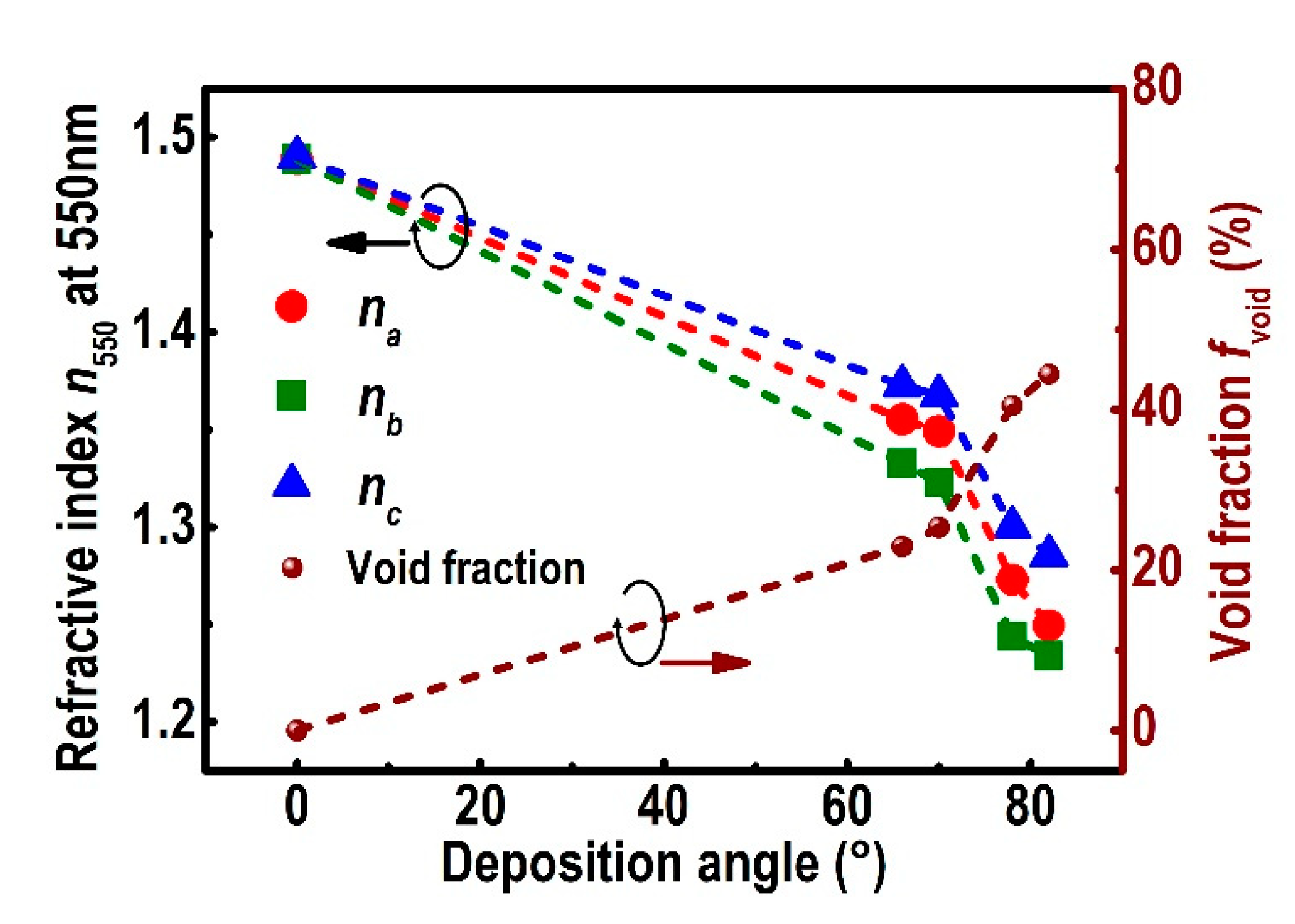
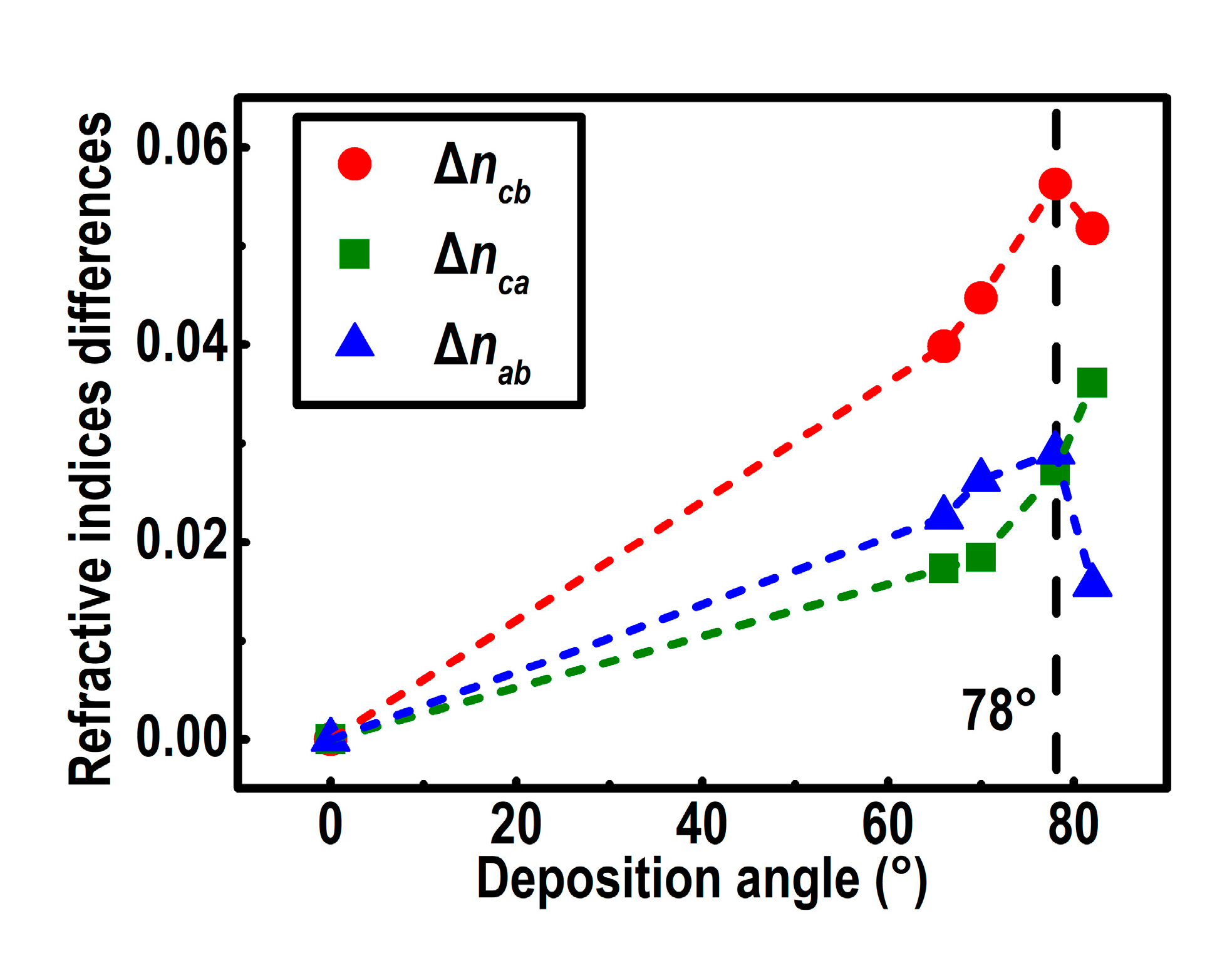
4.2. Optical Properties of YF3 CTFs

The optical properties of the prepared YF3 films were characterized by the MME. The dense YF3 films deposited at normal incidence of vapor flux (α = 0°) were characterized first to determine the dispersion function of YF3. The dispersion relations of the dense YF3 films were obtained by evaluating the 4 × 4 Mueller matrices [29,30]. The three-term Cauchy relation was used to describe the dispersion function of the YF3 films in the spectral range of 300−1650 nm, expressed as [31]
n = A + B λ 2 + C λ 4 ,
where the refractive index n is a function of the wavelength λ, and the fitting parameters A, B, and C are material-dependent constants in the model. The optical constants of the dense YF3 films were not affected appreciably by their thickness, which is much thicker than the nucleation layer [32]. The constants for the dense YF3 film were obtained to be A = 1.477 ± 0.0005, B = (3.559 ± 0.005) × 103 nm2, and C = 1.302 ± 0.005 nm4. The results are used as a baseline for comparing the YF3 CTFs deposited at the oblique incidence of vapor flux (α > 0°).
The YF3 CTFs deposited at α > 0° were characterized subsequently. The individual columns in the YF3 CTFs were assumed to satisfy the same dispersion functions as the dense YF3 film deposited at α = 0°. Figure 4 shows the experimental and the fitted Mueller matrix of the sample grown at α = 82° over the spectral range of 300−1650 nm, normalized by the M11. To interpret the MME data for the YF3 CTFs, structural parameters, i.e., the thickness d and the inclination angle θcol, are required to link to the Mueller matrix data through an appropriate optical model. A biaxial orthorhombic model, similar to that reported by Gospodyn et al., was selected to model the optical properties of the YF3 CTFs [32]. During the fitting process, the structure parameters d and θcol do not change with light wavelength, incident angle, and azimuth orientation.
The Bruggeman effective-medium approximation (EMA) was employed for the YF3 CTFs to evaluate the Mueller matrix data. The mixed medium was assumed to be composed of film material and void material [33]. The void material was assumed to be a medium with a refractive index of 1 and an extinction coefficient of 0 [32,33]. Since the CTF is a biaxial anisotropic medium, the direction-dependent Bruggeman EMA was applied accordingly. In this model, the volume fraction of YF3 was constrained to be constant in all directions for a certain point in the film. Thus, the effective dielectric constants along the principal axis are expressed as [34]
( 1 g j ) ε j 2 + B j ε j g j ε YF 3 = 0 ,   ( j = a , b , c ) ,
where Bj is given by
B j = ( g j f ) ε YF 3 ( 1 f g j ) ,
where f represents the volume fraction of YF3 in the film, and gj represents the depolarization factor for the optical j axis [35]. The void fraction fvoid is equal to 1 − f. The depolarization factors depend on the shape of the columns, with ga + gb + gc = 1. With the direction-dependent Bruggeman EMA, the effective principal dielectric constants εj are matched to the values obtained from the biaxial orthorhombic model by varying the fitting parameters ga, gb, f, and the bulk-like dielectric function εYF3.
The fitted refractive indices are depicted in Figure 5. All the three principal indices of refraction for the YF3 CTFs decrease slightly as the wavelength increases from 300 nm to 1650 nm. The value of nc is noted to be the highest of the three principal refractive indices. For example, na = 1.249, nb = 1.233, and nc = 1.286 are acquired for the 82°-deposited film at 550nm. Since the structure in the column direction can be regarded as laminar with the electric field parallel to the material layer, the measured depolarization factor along this axis is gc ≈ 0 [36].
The thickness d and the inclination angle θcol of YF3 films obtained from the SEM and the MME are shown in Figure 6. The MME results are consistent with the SEM results for two parameters. The difference between the two measurement results can be attributed to the fact that the SEM measurement was performed in the micrometer range while the MME measurement was performed in the millimeter range.
The relation between the deposition angle and the inclination angle fitted from MME is shown in Figure 7. The experimental values were fitted by the modified tangent-rule equation [37]
θ col = tan 1 ( E tan α ) ,
where the optimized value of the constant E in the equation is 0.153.
The principal refractive indices for YF3 films versus the deposition angle at 550 nm are shown in Figure 8. All the principal refractive indices decrease as the deposition angle increases from 66° to 82°. The refractive index perpendicular to the column direction (nb) for the sample deposited at α = 82° is approximately 1.233 at 550 nm, which is much lower than that of dense YF3 films (1.489 at 550 nm). According to the two-dimensional simulation predictions, the decrease in the refractive index of YF3 CTFs is caused by the decrease in the volume fraction of YF3 with the increase in the deposition angle α [38]. These results are consistent with studies on niobium pentoxide, magnesium fluoride, and tungsten oxide [12,32,39].
Figure 8 shows the void fraction fvoid calculated with the Bruggeman EMA versus the deposition angle. The void fraction of YF3 films increases with the increase in the deposition angle α. At α = 82°, the void fraction increases to approximately 45%, which implies that nearly half of the YF3 CTF is filled with voids. The high void fraction is the result of more separated and inclined columns due to the enhanced atomic self-shadowing effect and limited adatom diffusion [6]. By adjusting the angle of particle flux, the effective refractive index and the void fraction of YF3 CTF can be designed within a continuous range of values.
The highly oriented nanostructure of inclined columns indicates that the YF3 CTFs are biaxially anisotropic, with the long axis along the column direction [6]. The differences in the three principal indices of refraction, Δncb, Δnca, and Δnab, are used to quantify its anisotropy, which is defined by the absolute values of ncnb, ncna, and nanb, respectively. Figure 9 illustrates the refractive indices differences versus deposition angles at λ = 550 nm. At α = 78°, Δncb and Δnab reach the maximum 0.056 and 0.029, respectively. A larger deposition angle leads to an increase in Δnca, along with a decrease in Δncb and Δnab. The differences in the three principal refractive indices of the YF3 CTFs show a strong dependence on the deposition angle. A smaller deposition angle results in a smaller structural anisotropy of the film, as well as a minor optical anisotropy. However, a too oblique deposition angle will result in a low volume fraction of YF3 and a low effective refractive index of the film. The volume fraction of YF3 is another main factor affecting the difference in refractive index. The critical volume fraction of YF3 of the maximum refractive index differences is deduced to be 59.5% from Figure 8. The optimal deposition angle should balance these two competing factors to yield the maximum differences in the three principal refractive indices [13]. In addition, according to the results of the XRD measurements, the intrinsic YF3 is amorphous, which means the optical anisotropy caused by crystallization is negligible.
In practical application, the GLAD technique provides a solution for preparing a gradient- refractive-index structure, which can be used for anti-reflectors, solar cell absorbers, and radiative coolers [8,40]. The anisotropic structure of films prepared by the GLAD technique will also induce anisotropy in the thermal, electrical, and magnetic properties of thin films [11,25,41].

5. Conclusions

A series of YF3 CTFs with various column angles were fabricated by the GLAD method. The as-deposited YF3 films grown at different deposition angles were found to be amorphous. The columns of YF3 CTFs became increasingly separated and inclined as the deposition angle increased. The structural parameters obtained from the MME agree with those viewed from the FE-SEM images for inclination angle and physical thickness. The optical properties of the studied samples obtained from the MME measurement show that the highly oriented YF3 CTFs were biaxially anisotropic, with the highest refractive index along the column direction. The three principal refractive indices and the volume fraction of YF3 evaluated from the direction-dependent Bruggeman EMA decreased significantly as the deposition angle increased due to the self-shadowing effect and limited adatom diffusion. In addition, the refractive index differences of the columnar thin films in the three principal directions strongly depend on the deposition angle and the volume fraction of YF3.

Author Contributions

Writing—original draft preparation, Y.S.; Writing—review and editing, P.L., Y.C., H.Z., H.T., Y.Z., R.Z., S.W., J.L. and L.C.; Supervision, Y.Z. All authors have read and agreed to the published version of the manuscript.

Funding

This research was funded by the National Natural Science Foundation of China (61775042, 11674062) and the Fudan University-CIOMP Joint Fund (FC2017-003).

Acknowledgments

The authors would like to express their sincere thanks for the financial support by the National Natural Science Foundation of China (61775042, 11674062) and the Fudan University-CIOMP Joint Fund (FC2017-003).

Conflicts of Interest

The authors declare no conflict of interest.

References

  1. Barabasi, A.L.; Stanley, H.E. Fractal Concepts in Surface Growth; Cambridge U.P.: Cambridge, UK, 1995. [Google Scholar]
  2. Young, N.O.; Kowal, J. Optically active fluorite films. Nature 1959, 183, 104–105. [Google Scholar] [CrossRef]
  3. Petrov, I.; Barna, P.B.; Hultman, L.; Greene, J.E. Microstructural evolution during film growth. J. Vac. Sci. Technol. A 2003, 21, S117–S128. [Google Scholar] [CrossRef]
  4. Barranco, A.; Borras, A.; Gonzalez-Elipe, A.R.; Palmero, A. Perspectives on oblique angle deposition of thin films: From fundamentals to devices. Prog. Mater. Sci. 2016, 76, 59–153. [Google Scholar] [CrossRef] [Green Version]
  5. Vick, D.; Friedrich, L.J.; Dew, S.K.; Brett, M.J.; Robbie, K.; Seto, M.; Smy, T. Self-shadowing and surface diffusion effects in obliquely deposited thin films. Thin Solid Films 1999, 339, 88–94. [Google Scholar] [CrossRef]
  6. Kranenburg, H.; Lodder, C. Tailoring growth and local composition by oblique-incidence deposition: A review and new experimental data. Mater. Sci. Eng. R 1994, 11, 295–354. [Google Scholar] [CrossRef] [Green Version]
  7. Kuo, M.-L.; Poxson, D.J.; Kim, Y.S.; Mont, F.W.; Kim, J.K.; Schubert, E.F.; Lin, S.-Y. Realization of a near-perfect antireflection coating for silicon solar energy utilization. Opt. Lett. 2008, 33, 2527–2529. [Google Scholar] [CrossRef]
  8. Xi, J.Q.; Schubert, M.F.; Kim, J.K.; Schubert, E.F.; Chen, M.; Lin, S.-Y.; Liu, W.; Smart, J.A. Optical thin-film materials with low refractive index for broadband elimination of Fresnel reflection. Nat. Photonics 2007, 1, 176–179. [Google Scholar] [CrossRef]
  9. Khudhayer, W.J.; Kariuki, N.N.; Wang, X.; Myers, D.J.; Shaikh, A.U.; Karabacak, T. Oxygen reduction reaction electrocatalytic activity of glancing angle deposited platinum nanorod arrays. J. Electrochem. Soc. 2011, 158, B1029–B1041. [Google Scholar] [CrossRef] [Green Version]
  10. Yuan, J.; Wang, B.; Wang, H.; Chai, Y.; Jin, Y.; Qi, H.; Shao, J. Electrochromic behavior of WO3 thin films prepared by GLAD. Appl. Surf. Sci. 2018, 447, 471–478. [Google Scholar] [CrossRef]
  11. Sun, Y.; Xiao, X.; Xu, G.; Dong, G.; Chai, G.; Zhang, H.; Liu, P.; Zhu, H.; Zhan, Y. Anisotropic vanadium dioxide sculptured thin films with superior thermochromic properties. Sci. Rep. 2013, 3, 1–10. [Google Scholar] [CrossRef] [Green Version]
  12. Xiao, X.; Dong, G.; Xu, C.; He, H.; Qi, H.; Fan, Z.; Shao, J. Structure and optical properties of Nb2O5 sculptured thin films by glancing angle deposition. Appl. Surf. Sci. 2008, 255, 2192–2195. [Google Scholar] [CrossRef]
  13. Motohiro, T.; Taga, Y. Thin film retardation plate by oblique deposition. Appl. Opt. 1989, 28, 2466–2482. [Google Scholar] [CrossRef]
  14. Hodgkinson, I.; Wu, Q.H. Birefringent thin-film polarizers for use at normal incidence and with planar technologies. Appl. Phys. Lett. 1999, 74, 1794–1796. [Google Scholar] [CrossRef]
  15. Kaminska, K.; Robbie, K. Birefringent omnidirectional reflector. Appl. Opt. 2004, 43, 1570–1576. [Google Scholar] [CrossRef]
  16. Toader, O.; John, S. Proposed square spiral microfabrication architecture for large three-dimensional photonic band gap crystals. Science 2001, 292, 1133–1135. [Google Scholar] [CrossRef]
  17. Chen, G.; Qiu, H.; Fan, R.; Hao, S.; Tan, S.; Yang, C.; Han, G. Lanthanide-doped ultrasmall yttrium fluoride nanoparticles with enhanced multicolor upconversion photoluminescence. J. Mater. Chem. 2012, 22, 20190–20196. [Google Scholar] [CrossRef]
  18. Condorelli, G.G.; Anastasi, G.; Fragalà, I.L. MOCVD of YF3 and Y1–xErxF3 thin films from precursors synthesized in Situ. Chem. Vap. Depos. 2005, 11, 324–329. [Google Scholar] [CrossRef]
  19. Barrioz, V.; Irvine, S.J.C.; Jones, D.P. In situ and ex situ stress measurements of YF3 single layer optical coatings deposited by electron beam evaporator. J. Mater. Sci. Mater. Electron. 2003, 14, 559–566. [Google Scholar] [CrossRef]
  20. Pilvi, T.; Puukilainen, E.; Munnik, F.; Leskelä, M.; Ritala, M. ALD of YF3 thin films from TiF4 and Y(thd)3 precursors. Chem. Vap. Depos. 2009, 15, 27–32. [Google Scholar] [CrossRef]
  21. Chindaudom, P.; Vedam, K. Characterization of inhomogeneous transparent thin films on transparent substrates by spectroscopic ellipsometry: Refractive indices n(λ) of some fluoride coating materials. Appl. Opt. 1994, 33, 2664–2671. [Google Scholar] [CrossRef]
  22. Pellicori, S.F.; Colton, E. Fluoride compounds for IR coatings. Thin Solid Films 1992, 209, 109–115. [Google Scholar] [CrossRef]
  23. Lemarquis, F.; Marchand, G.; Amra, C. Design and manufacture of low-absorption ZnS–YF3 antireflection coatings in the 3.5–16-μm spectral range. Appl. Opt. 1998, 37, 4239–4244. [Google Scholar] [CrossRef] [PubMed]
  24. Goldstein, D.H. Mueller matrix dual-rotating retarder polarimeter. Appl. Opt. 1992, 31, 6676–6683. [Google Scholar] [CrossRef]
  25. Huang, C.Y.T.; Kargar, F.; Debnath, T.; Debnath, B.; Valentin, M.D.; Synowicki, R.; Schoeche, S.; Lake, R.K.; Balandin, A.A. Phononic and photonic properties of shape-engineered silicon nanoscale pillar arrays. Nanotechnology 2020, 31, 30LT01. [Google Scholar] [CrossRef]
  26. Robbie, K.; Brett, M.J.; Lakhtakia, A. Chiral sculptured thin films. Nature 1996, 384, 616. [Google Scholar] [CrossRef]
  27. Tompkins, H.G.; Eugene, A.I. Handbook of Ellipsometry; William Andrew Inc.: New York, NY, USA, 2005. [Google Scholar]
  28. Arwin, H.; Berlind, T.; Johs, B.; Järrendahl, K. Cuticle structure of the scarab beetle Cetonia aurata analyzed by regression analysis of Mueller-matrix ellipsometric data. Opt. Express 2013, 21, 22645–22656. [Google Scholar] [CrossRef] [Green Version]
  29. Berreman, D.W. Optics in stratified and anisotropic media: 4×4-matrix formulation. J. Opt. Soc. Am. 1972, 62, 502–510. [Google Scholar] [CrossRef]
  30. Schubert, M. Polarization-dependent optical parameters of arbitrarily anisotropic homogeneous layered systems. Phys. Rev. B 1996, 53, 4265–4274. [Google Scholar] [CrossRef]
  31. Lei, P.; Zhu, J.; Zhu, Y.; Han, J. Preparation and optical properties of sputtered-deposition yttrium fluoride film. Nucl. Instrum. Methods Phys. Res. Sect. B 2013, 307, 429–433. [Google Scholar]
  32. Gospodyn, J.; Sit, J.C. Characterization of dielectric columnar thin films by variable angle Mueller matrix and spectroscopic ellipsometry. Opt. Mater. 2006, 29, 318–325. [Google Scholar] [CrossRef]
  33. Spanier, J.E.; Herman, I.P. Use of hybrid phenomenological and statistical effective-medium theories of dielectric functions to model the infrared reflectance of porous SiC films. Phys. Rev. B 2000, 61, 10437–10450. [Google Scholar] [CrossRef] [Green Version]
  34. Wang, X.J.; Abell, J.L.; Zhao, Y.P.; Zhang, Z.M. Angle-resolved reflectance of obliquely aligned silver nanorods. Appl. Opt. 2012, 51, 1521–1531. [Google Scholar] [CrossRef]
  35. Polder, D.; van Santeen, J.H. The effective permeability of mixtures of solids. Physica 1946, 12, 257–271. [Google Scholar] [CrossRef]
  36. Aspnes, D.E. Optical properties of thin films. Thin Solid Films 1982, 89, 249–262. [Google Scholar] [CrossRef]
  37. Hodgkinson, I.; Wu, Q.h.; Hazel, J. Empirical equations for the principal refractive indices and column angle of obliquely deposited films of tantalum oxide, titanium oxide, and zirconium oxide. Appl. Opt. 1998, 37, 2653–2659. [Google Scholar] [CrossRef]
  38. Tait, R.N.; Smy, T.; Brett, M.J. Modelling and characterization of columnar growth in evaporated films. Thin Solid Films 1993, 226, 196–201. [Google Scholar] [CrossRef]
  39. Charles, C.; Martin, N.; Devel, M.; Ollitrault, J.; Billard, A. Correlation between structural and optical properties of WO3 thin films sputter deposited by glancing angle deposition. Thin Solid Films 2013, 534, 275–281. [Google Scholar] [CrossRef] [Green Version]
  40. Hossain, M.M.; Gu, M. Radiative cooling: Principles, progress, and potentials. Adv. Sci. 2016, 3, 1500360. [Google Scholar] [CrossRef]
  41. Chaffar Akkari, F.; Ben Jbara, H.; Abdelkader, D.; Gallas, B.; Kanzari, M. Effect of angle deposition γ on the structural, optical and electrical properties of copper oxide zigzag (+γ, −γ) nanostructures elaborated by glancing angle deposition. Thin Solid Films 2018, 657, 61–69. [Google Scholar] [CrossRef]
Figure 1. (a) Schematic diagram of the glancing angle deposition (GLAD) method for electron beam evaporation, (b) columnar thin film fabricated by the GLAD method, and (c) the laboratory coordinate system (x, y, z) and the principal coordinate system (a, b, c).
Nanomaterials 10 02413 g001
Figure 2. XRD patterns of yttrium fluoride (YF3) films deposited at the angles of 0° (a), 70° (b), and 82° (c).
Nanomaterials 10 02413 g002
Figure 3. Top views (ad) and cross-sectional views (eh) of the FE-SEM images for YF3 films deposited at 0° (a,e), 70° (b,f), 78° (c,g), and 82° (d,h), respectively.
Nanomaterials 10 02413 g003
Figure 4. Measured (blue dots) and simulated (red lines) Mueller matrix elements normalized by the M11 for the YF3 sample prepared at a deposition angle α = 82° in the wavelength range of 300−1650 nm. The measurements were performed at a light incident angle θ = 65° and an azimuth orientation ϕ = 0°.
Nanomaterials 10 02413 g004
Figure 5. Principal refractive indices na (dashed lines), nb (dotted lines), and nc (solid lines) of the biaxial YF3 columnar thin films (CTFs) at deposition angles of 0°, 70°, and 82°, respectively.
Nanomaterials 10 02413 g005
Figure 6. Physical thickness d and inclination angle θcol of YF3 films measured by SEM and Mueller matrix ellipsometry (MME).
Nanomaterials 10 02413 g006
Figure 7. The inclination angle for YF3 CTFs versus the deposition angle. The filled squares indicate the experimental values, and the solid curve indicates the predicted values by the modified tangent-rule equation.
Nanomaterials 10 02413 g007
Figure 8. Void fractions and principal refractive indices na (red dots), nb (green squares), and nc (blue triangles) at 550 nm for the YF3 columnar films grown at various deposition angles. Dashed lines are guides for the eye.
Nanomaterials 10 02413 g008
Figure 9. Refractive indices differences Δncb (red dots), Δnca (green squares), and Δnab (blue triangles) at 550 nm for YF3 films versus deposition angle. Dashed lines are guides for the eye.
Nanomaterials 10 02413 g009
Publisher’s Note: MDPI stays neutral with regard to jurisdictional claims in published maps and institutional affiliations.

