Article

Amorphous Mo5O14-Type/Carbon Nanocomposite with Enhanced Electrochemical Capability for Lithium-Ion Batteries

1
National Research Centre, Inorganic Chemistry Department, 33 El Bohouth St. (former El Tahrir St.), Dokki, Giza P.O.12622, Egypt
2
Karlsruhe Institute of Technology (KIT), Institute for Applied Materials (IAM), Hermann-von-Helmholtz-Platz 1, D-76344 Eggenstein-Leopoldshafen, Germany
3
Institut de Minéralogie, de Physique des Matériaux et de Cosmologie (IMPMC), Campus Pierre et Marie, Sorbonne Université, UMR 7590, 4 place Jussieu, 75005 Paris, France
*
Author to whom correspondence should be addressed.
Nanomaterials 2020, 10(1), 8; https://doi.org/10.3390/nano10010008
Submission received: 12 November 2019 / Revised: 14 December 2019 / Accepted: 17 December 2019 / Published: 18 December 2019
(This article belongs to the Special Issue Metal-Oxide Nanomaterials for Energy Application)

Abstract

:
An amorphous MomO3m−1/carbon nanocomposite (m ≈ 5) is fabricated from a citrate–gel precursor heated at moderate temperature (500 °C) in inert (argon) atmosphere. The as-prepared Mo5O14-type/C material is compared to α-MoO3 synthesized from the same precursor in air. The morphology and microstructure of the as-prepared samples are characterized by scanning electron microscopy (SEM), X-ray diffraction (XRD), and Raman scattering (RS) spectroscopy. Thermal gravimetry and elemental analysis indicate the presence of 25.8 ± 0.2% of carbon in the composite. The SEM images show that Mo5O14 is immersed inside a honeycomb-like carbon matrix providing high surface area. The RS spectrum of Mo5O14/C demonstrates an oxygen deficiency in the molybdenum oxide and the presence of a partially graphitized carbon. Outstanding improvement in electrochemical performance is obtained for the Mo5O14 encapsulated by carbon in comparison with the carbon-free MoO3.

1. Introduction

Due to their numerous applications including their vital role as light weight, long life and high-energy density power sources, special attention has been directed towards lithium-ion batteries (LIBs). These power sources find major applications from portable electronic appliances to electric vehicles. As the positive electrode plays a major role in the electrochemical performance of the LIBs, many efforts of research are currently made on active electrode materials with high capability and long cycling life [1]. Among the molybdenum-oxide series evaluated as electrode materials, α-MoO3 and MoO2 are thermodynamically stable phases. They crystallize in a unique layered structure (orthorhombic, Pbnma space group) and a rutile-like structure (monoclinic P21/c space group), respectively [2]. In the same Mo-O binary system, the oxygen deficient MomO3m−1 phases include Mo4O11, Mo5O14, Mo8O23, Mo9O26, and Mo17O47, which crystallize in the so-called Magnéli phases described in details by Kihlborg [3]. These oxides have been identified as derived from MoO3 by shear mechanism with networks of MoO6 octahedra. These units are connected in three dimensions with empty parallel tunnels involving the presence of potential sites for hosting Li+ ions. They are performant cathode materials in non-aqueous lithium cells [4,5,6,7,8]. Few works reporting the lithiation of Mo5O14 are available in the literature [5,9,10,11]. Preliminary patterns of the fully lithiated Mo5O14 crystal suggest that the unit cell expands in the b direction and contracts in both the a and c directions upon insertion of lithium [9]. Cignini et al. reported a specific capacity of 310 mA g−1 for Mo5O14 as the positive electrode of a primary Li cell discharged at 0.5 mA cm−2 and 1.0 V cut-off. [5]. Nazri and Julien [10] showed that MoO2.8, an oxygen-deficient Mo5O14 prepared by dehydration and annealing treatment of molybdic acid powder (MoO3·1H2O) at 750 °C, exhibited a high electrical conductivity of 10−2 S cm−1. Such a material displayed an excellent reversible capacity (1.45 Li/Mo) in cells with 1 mol L−1 LiClO4 in propylene carbonate (PC) electrolyte in the potential range 3.3–1.3 V vs. Li+/Li.
However, MoO3 and MomO3m−1 lithiated oxides suffer from a large volume expansion (about 104% for MoO3). During Li+ insertion, pulverization of the cathode occurs at a potential of less than 1.5 V and disconnection from the current collector. As a result, the electrochemical performance is poor [12]. Different strategies can be used to improve the cyclability as follows. Nanosized MomO3m−1 particles were prepared with low crystallinity [13,14]. Blended hybrid was fabricated [15]. Composites with addition of an electronically-conductive carbonaceous materials were synthesized [12,16,17,18,19]. The carbon has two beneficial effects: it opposes the aggregation of the active particles and it accommodates the volume change of electrode material during cycling [17]. Different synthesis techniques were used to fabricate MoO3/C composites: electrospinning method [18], hydrothermal route [12,16,19,20], template method [21], spray pyrolysis [22] and ball milling [23].
In this paper, a nanocomposite of oxygen-deficient MomO3m−1/carbon is synthesized by a sol-gel method using citric acid as chelating agent. The calcination of dried precursor in argon atmosphere results in the formation of the amorphous-like Mo5O14 (MoO2.8) oxide immersed in a carbon matrix. This new material is characterized by X-ray diffraction (XRD), scanning electron microscopy (SEM), surface area analysis (BET) and Raman scattering (RS) spectroscopy. Finally, electrochemical properties of MoO3/C composite for lithium ion batteries were also investigated for comparison.

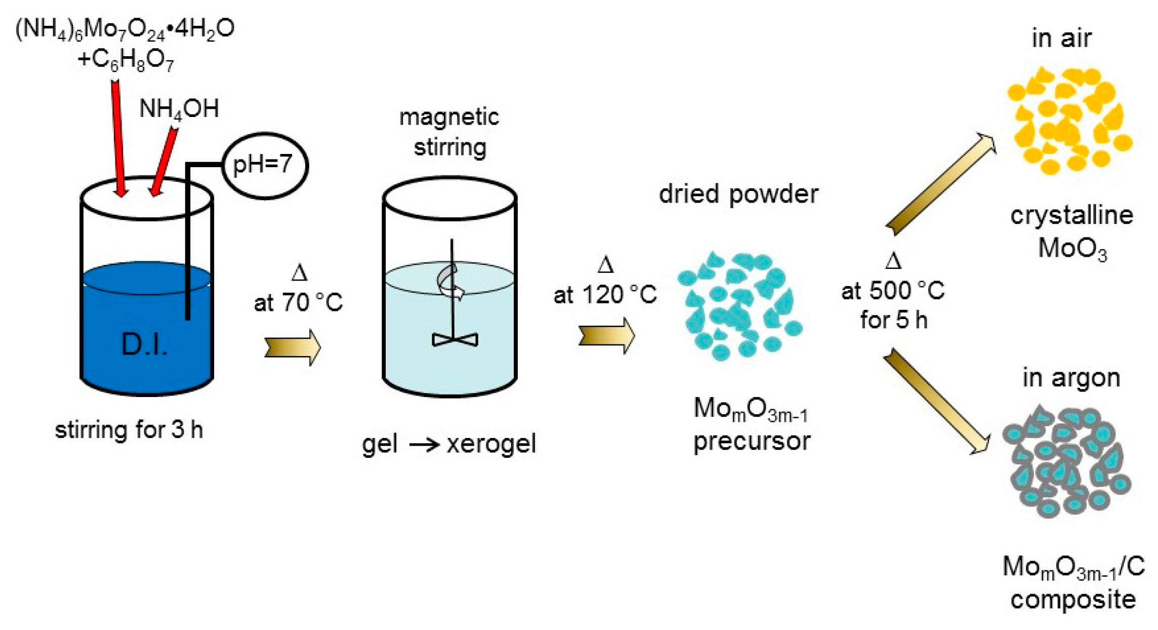
2. Materials and Methods

Pure MoO3 (P-MoO3) sample and MomO3m−1/C nanocomposite were prepared by a citrate–gel method using ammonium molybdate tetrahydrate (AMT, (NH4)6Mo7O24∙4H2O). First, a stoichiometric amount of AMT was dissolved in de-ionized water (DI) and stepwise added to the stirring aqueous solution of citric acid (CA) with metal/CA ratio of 1:1 under neutral pH adjusted with ammonium hydroxide; Second, the overall solution was stirred for 3 h to form homogenous mixture through reaction between the metal ion and the chelating agent. Transparent gel was formed after a slow evaporation of the solution heated at 70 °C. Furthermore, continuous heating with stirring led to the transformation of the gel to xerogel, which converted to powder by further drying at ca. 120 °C. Pure MoO3 crystals were obtained by calcining the milled precursor at 500 °C for 5 h in air, while the MomO3m−1/C composite was formed under argon atmosphere. The overall synthesis process is presented in Scheme 1.
The composition was determined by thermal gravimetric analysis (TGA) and differential scanning calorimetry (DSC) using an analyzer model TGA-7 series (Perkin Elmer, Waltham, MA, USA,) in the temperature range of 30–1000 °C in air at a heating rate of 10 °C min−1. Elemental analysis was performed using a CHNOS analyzer (Elementar Analysen Systeme GmbH, Langenselbold, Germany). The structure of the samples was analyzed by X-ray diffraction (XRD) using a X’Pert diffractometer (Philips, Hamburg, Germany) equipped with a CuKα X-ray source (λ = 1.54056 Å). Data were collected in the 2θ range of 10–80°. The particle morphology was examined by scanning electron microscopy (SEM) (JEOL microscope, Akishima, Japan). Raman spectra were collected at a spectral resolution of 2 cm−1 with a double monochromator (Jobin-Yvon model U1000) using the 514.5 nm line of an Ar-ion laser (Spectra-Physics 2020) in a backscattering geometry. The laser power was kept below 25 mW to prevent the sample degradation by the laser spot. The specific surface area was measured by nitrogen adsorption/desorption at 77 K using the Brunauer-Emmett-Teller (BET) method (Quantachrome NOVA Automated Gas Sorption).
Electrochemical properties were investigated by cyclic voltammetry (CV) and galvanostatic charge-discharge (GCD) techniques. The cathodes were prepared by mixing 80% (w/w) of the active material, 10% (w/w) super C65 carbon (TIMCAL, Lac-des-Iles, Canada) and 10% (w/w) polyvinylidenefluoride (Solef PVdF 6020 binder, Solvay, Brussels, Belgium), in N-methyl-2-pyrrolidone (NMP, Sigma-Aldrich, St. Louis, MO, USA) to get a slurry, which was coated on copper foil at a loading of 2.1 mg cm−2. After drying over night at 80 °C, discs were punched out of this film with a diameter of 1.4 cm. The 2032-type coin cells were assembled in an argon-filled glove box with lithium foil (Alfa Aesar, Haverhill, MA, USA) as the anode, 1 mol L−1 LiPF6 in ethylene carbonate:dimethyl carbonate (EC:DMC) = 50:50 (v/v) (LP30, Sigma-Aldrich, battery grade) as the electrolyte, and glass microfiber filters (Whatmann®-GF/D 70 mm Ø) as the separator. A multi-channel potentiostat (VMP3, Bio-Logic, Seyssinet-Pariset, France) was used to test the electrochemical performance of the electrodes at 25 °C in the voltage range of 0.6–3.5 V vs. Li+/Li.

3. Results

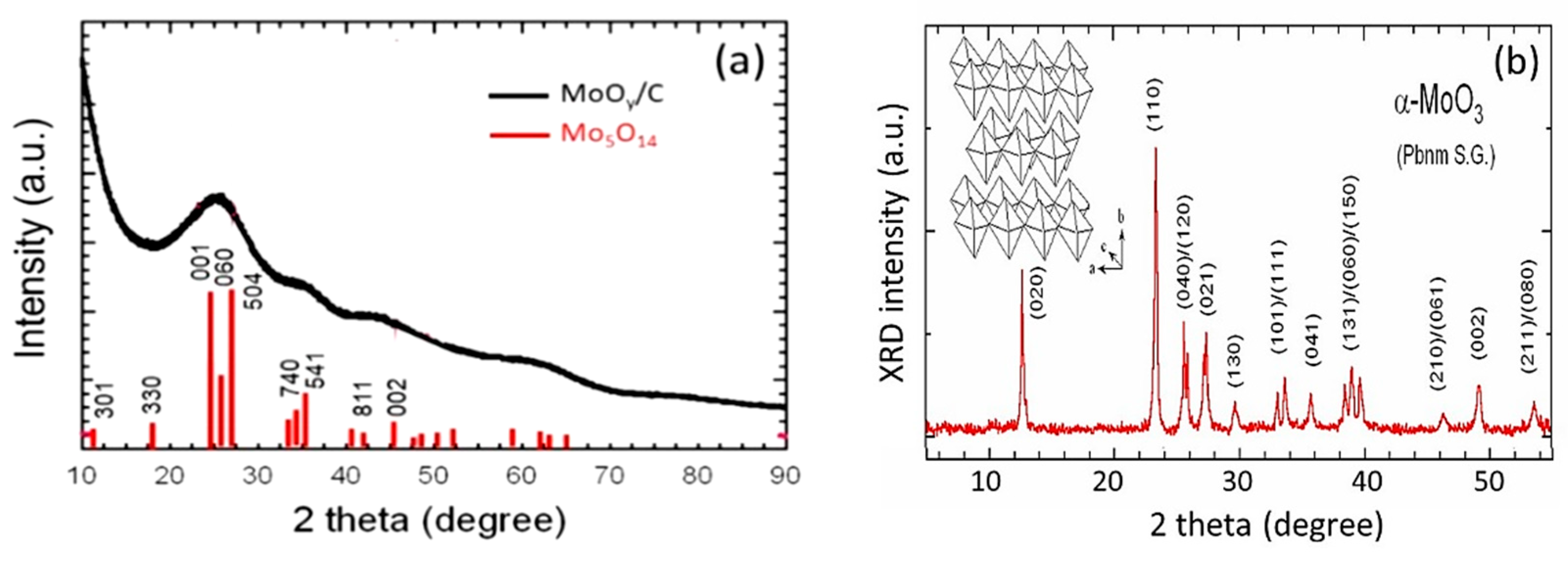
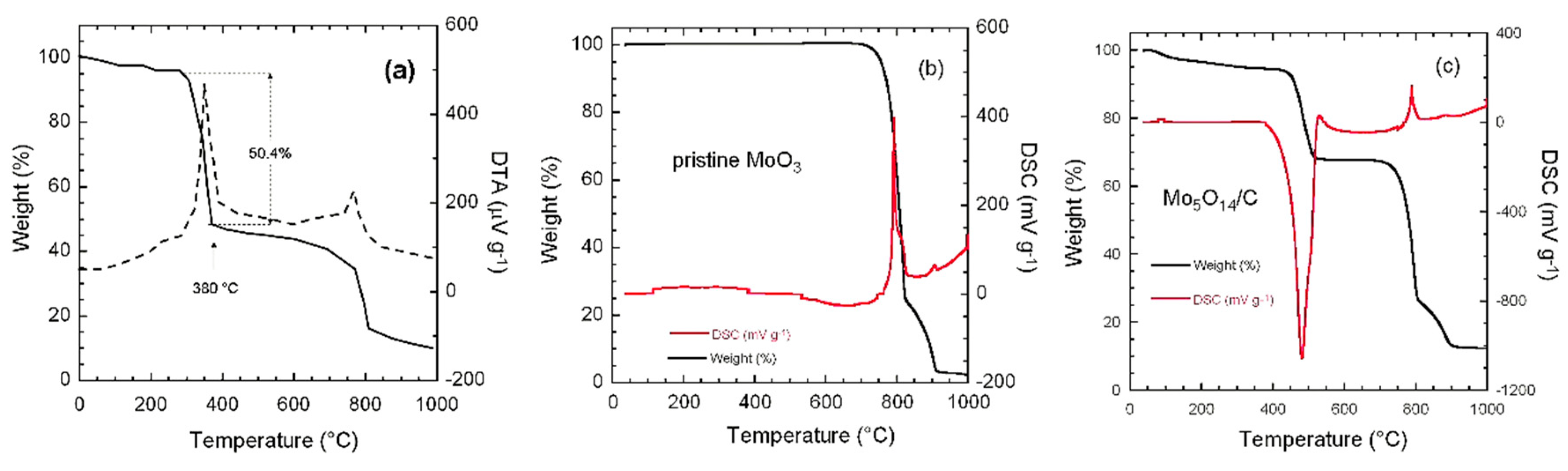
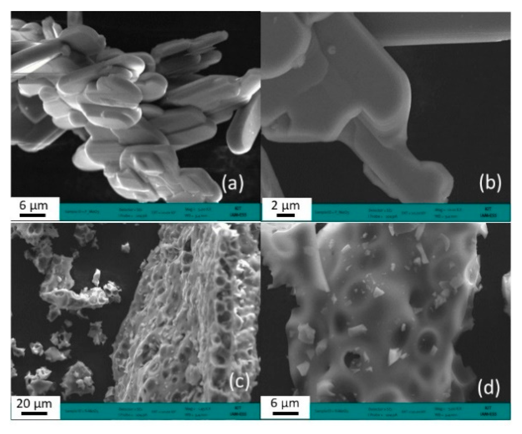
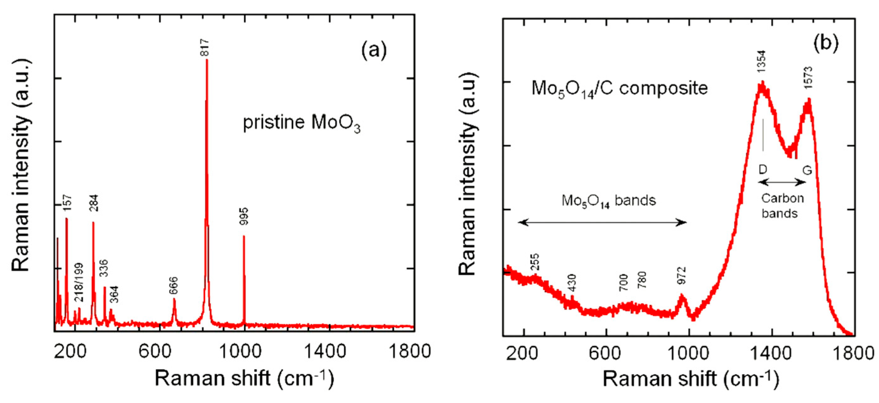
3.1. Structure and Morphology

Figure 1a shows the XRD pattern of the molybdenum oxide/carbon composite obtained by calcination of ammonium molybdate tetrahydrate in argon atmosphere. This diagram exhibits four broad peaks centered at 2θ angles of 25.7, 35.1, 43.5 and 62.2°, which suggest a quasi-amorphous texture of the Mo oxide in a carbon matrix obtained by the decomposition of the chelating agent in absence of oxygen. The pattern shown in Figure 1a compares well to that of the tetragonal Mo5O14 phase (P4/mbm space group, a = 2.2989 nm, and c = 0.3936 nm) reported by Kihlborg [24]. Note this composition deduced form this XRD pattern implies the molybdenum valence distribution Mo6+3Mo5+2. This valence mixing in turn implies a high concentration of free carriers and thus a large electrical conductivity, which will be beneficial to the electrochemical properties. The crystal structure of Mo5O14 can be depicted as complexes of linked MoO6 octahedra and MoO7 pentagonal bipyramids [25]. The peak at 2θ = 25.7° corresponds to the overlapping (001), (060) and (504) lines of the Mo5O14 lattice, while the less intense peaks at 2θ = 35.1° and 43.5° coincide with the (541) and (002) Bragg lines of the tetragonal structure, respectively [26]. The crystallite size calculated by the Scherrer’s formula from the full-width of the broad line at 2θ = 25.7° is found to be 2.9 nm. The presence of the disordered carbon (low degree of graphitization) is evidenced by the main signal at 2θ ≈ 26° ((002) Bragg line) probably overlapping with the main signals of the Mo5O14 phase. However, the amorphous nature of carbon deposited on the Mo oxide at a low temperature of 500 °C is confirmed by the absence of the (100) and (101) carbon-related peaks in the 40–45° 2θ range [16]. The formation of an amorphous Mo5O14/C composite under argon gas is due to the presence of CO and CO2 gases generated by the combustion reaction of the carbon source using citric acid, which reduces the Mo6+ ions of the ammonium molybdate. The TGA experiments performed during the synthesis (Figure 2a) present a strong exothermic peak at ca. 380 °C, which corresponds to the combustion of the organic compound C6H8O7 accompanied by the decomposition of (NH4)6Mo7O24 (partial desorption of H2O and NH3) into oxides. At this stage, a weight loss of almost 50% was recorded.
The XRD pattern of P-MoO3 (Figure 1b) displays the typical pattern of a well-crystallized α-MoO3 phase that can be indexed in the orthorhombic Pbnm space group (JPCDS card 76-1003). The coarse-grained powder presents a preferred orientation of (0k0) planes, as the (020), (040) and (060) Bragg lines have a large intensity. Rietveld refinement provided lattice constants of a = 0.3965 Å, b = 1.3861 Å, and c = 0.3697 Å.
The carbon content of the Mo5O14/C composite synthesized by sol-gel method was determined using thermal gravimetry (TG) and the differential scanning colorimetric (DSC) experiments. Figure 2b,c show the TG curves of the as-prepared P-MoO3 and the Mo5O14/C composite, respectively, recorded in the range 25–1000 °C in air. The thermal behavior of P-MoO3 does not show obvious weight loss until the decomposition of MoO3 (melting point at ca. 795 °C) [27]. The situation for the Mo5O14/C composite is different. The TG curve shows a strong endothermic peak at ~500 °C with a weigh loss of 26% corresponding to the evolution of CO2 through reaction between carbon in the composite and the atmospheric oxygen. Thus, the composite contains 26% carbon coming from the pyrolysis of citric acid. Upon further heating, the small exothermic peak appearing at ca. 800 °C is attributed to the melting of Mo5O14 in the composite similarly to the feature observed for pure MoO3 crystal. Further elemental determination of carbon was performed using a CHNOS analyzer that gave the same percentage of carbon (25.8 ± 0.2%) in the composite.
The morphology of the Mo5O14/C composite was analyzed by scanning electron microscopy and compared with that of pure MoO3 synthesized from the same precursor (Figure 3). While the SEM images (a,b) of P-MoO3 show uniformly distributed and well-developed packed platelets of the layered α-MoO3 structure, the SEM images (c,d) of the Mo5O14/C composite display a honeycomb carbon matrix with small pores, and irregular particles of molybdenum oxide are dispersed inside the matrix.
Since XRD experiments are not efficient tools to determine the structure of ill-crystallized materials, we investigated the short-range local structure of Mo5O14/C composite using Raman spectroscopy. Figure 4 compares the Raman patterns of the pristine MoO3 (a) and the Mo5O14/C composite (b). The Raman spectrum of Mo5O14/C composite prepared at 500 °C in argon atmosphere can be considered as the sum of the Mo5O14 and carbon contribution. In the low-frequency region, the spectrum shows features of the molybdenum oxide phase, while the high-frequency range (greater than 1200 cm−1) displays the fingerprint of the carbon matrix. Note that the weak intensity of Mo5O14 Raman pattern is due to the presence of carbon environment absorbing the scattering light. The five low-frequency Raman bands located at 972, 780, 700, 430 and 225 cm−1 can be identified as the vibrational patterns of tetragonal Mo5O14. The Mo-O stretching mode appears at 972 cm−1, the Mo-O-Mo bridging modes are recorded at 780, 700 and 430 cm−1, while the deformation modes of the Mo-O bonds appear at ca. 225 cm−1. This deformation mode was observed at 229 cm−1 in Mo4O11. It should be noted that this Raman spectrum definitely differs from those of either α-MoO3 (Figure 4a) or Mo4O11 phase [28,29]. For example, in the spectrum of Mo5O14, the broad peak at ~780 cm−1 replaces the sharp peak of α-MoO3 at 820 cm−1, which reveals the presence of sub-stoichiometric MomO3m−1 crystals. Such a blue shift of the stretching mode is attributed to the modification of Mo-O bonds induced by the reduction of Mo6+ to Mo5+ next to the oxygen vacancies [30]. Nazri and Julien [31] showed that the intensities and positions of vibrational bands of MoO3·nH2O are extremely sensitive to small changes of the Mo-O polyhedra. A loss of the translational symmetry is expected because of the oxygen vacancies present in the MomO3m−1 lattice. Thus, the highest stretching mode appears at 996 cm−1 in MoO3, while it is shifted to 985 cm−1 in Mo4O11. The Hardcastle–Wachs approach allows to correlate the Raman shifts with the Mo–O bond distances [32]. The stretching at 972 cm−1 observed in the Raman spectrum of Mo5O14 appears at the same frequency as that of MoO3·nH2O with a Mo-O distance of 1.687 Å against 1.671 Å for anhydrous α-MoO3. The broad bands observed in the range 1200–1600 cm−1 correspond to the D- and G-bands of carbon. The D-band at 1354 cm−1 is associated with the disorder-allowed A1g zone-edge mode of graphite, whereas the G-band centered at 1573 cm−1 corresponds to the optically allowed E2g zone center mode of crystalline graphite. The broadening of the G- and D-bands are characteristics of localized in-plane sp2 domains, and disordered graphitic-like carbon, respectively. The peak intensity ratio ID/IG of approximately 1.19 confirms the low degree of graphitization of the carbon matrix and the small size of the graphitic domains La of about 4.8 nm according to the empirical equation La (nm) = 4.4 ID/IG [33]. The limited graphitization is due to the low temperature used for the preparation of the composite (i.e., 500 °C), but seems enough to be beneficial for electron transport from/to the semiconducting Mo5O14 active material.

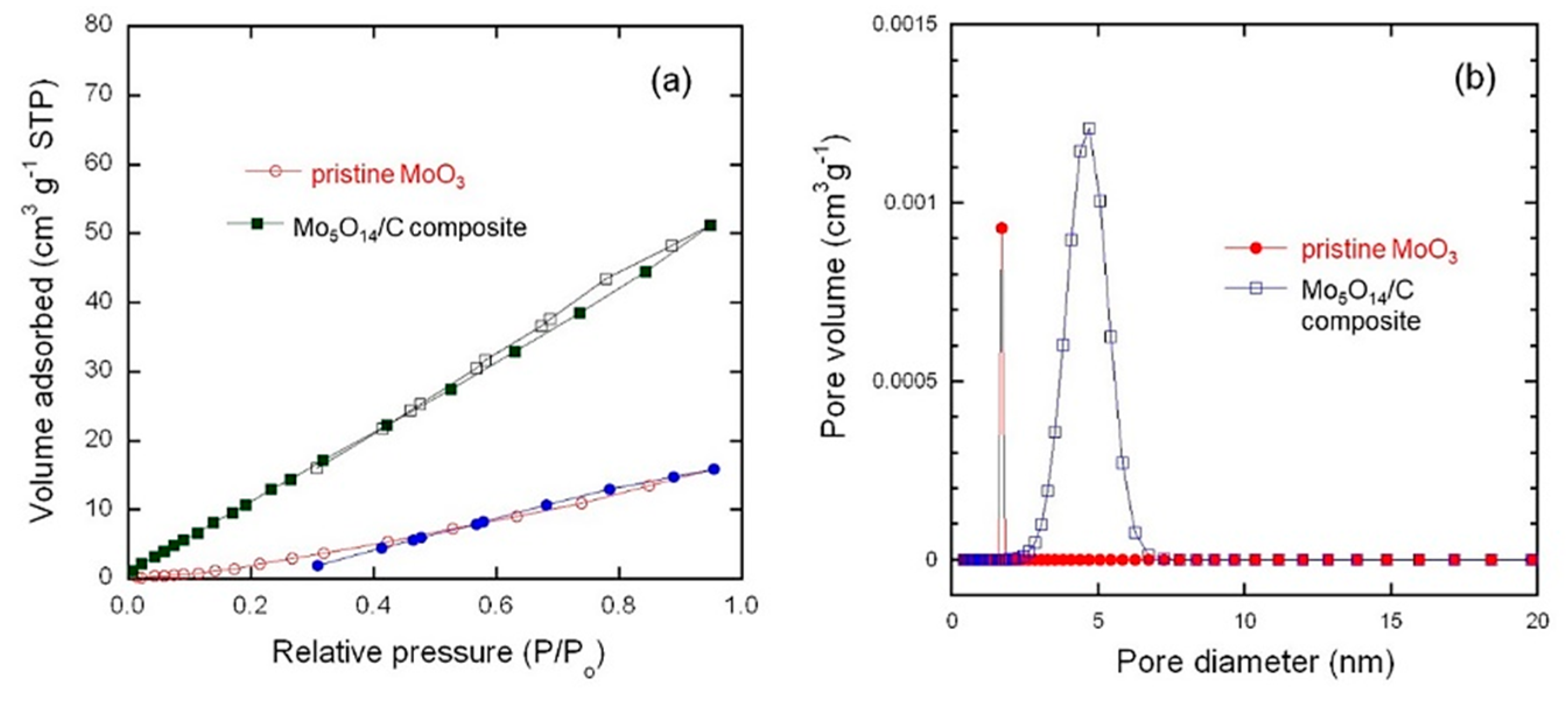
3.2. BET-Surface Area

Figure 5 shows the nitrogen adsorption–desorption isotherms and pore-size distributions (PSD) for both P-MoO3 and Mo5O14/C composite. The uptake of nitrogen adsorption of both samples increases gradually with the increase of relative pressure (Figure 5a). Note that the quantity of nitrogen adsorbed for the Mo5O14/C composite is much larger than that of P-MoO3 sample. The adsorption rises noticeably at low relative pressures of less than 0.5, indicating that micropores are present. Instead of reaching a plateau, the uptake of nitrogen further increases with relative pressure until P/P0 approaches unity, which suggests that a substantial amount of external surface area was created in Mo5O14/C sample. As shown in PSD curves (Figure 5b), the distribution of the pore diameters has peaks at 4.8 nm for Mo5O14/C composite. The Mo5O14/C composite exhibits a broader pore-size distribution with the pore diameter in the range 2−7 nm. It has been widely reported that physical and chemical activation of carbon materials help to open and widen the microporosity even with a conversion to mesopores [34,35]. The material porosity, i.e., pore size distribution and pore volume, has been quantitatively evaluated using the Barrett–Joyner–Halenda (BJH) method [36]. Results are listed in Table 1 and show that the BET surface area, the BJH total pore volume and the porosity are higher in Mo5O14/C than in P-MoO3. The increase of the specific surface area is attributed to the presence of 26 wt.% carbon. The higher pore size in the Mo5O14-type/C composite also favors better electrochemical performance of the electrode.

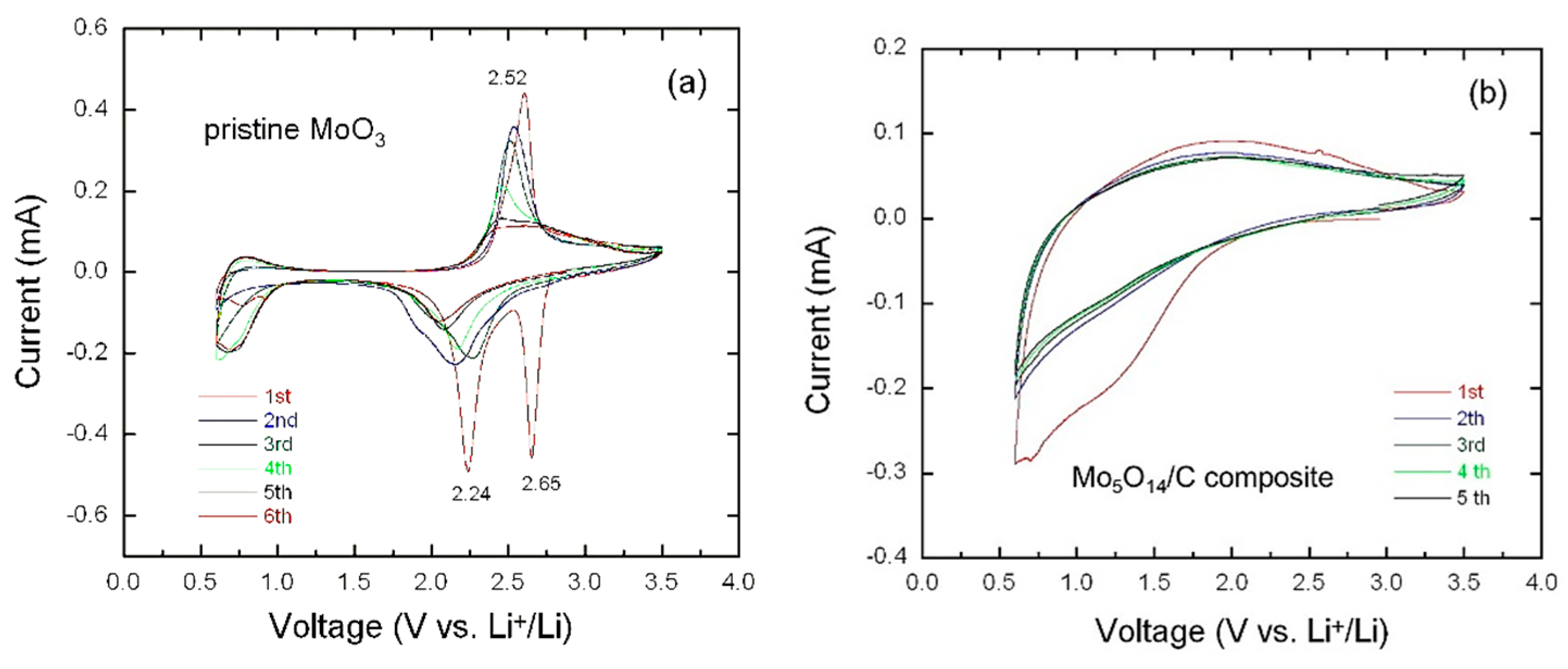
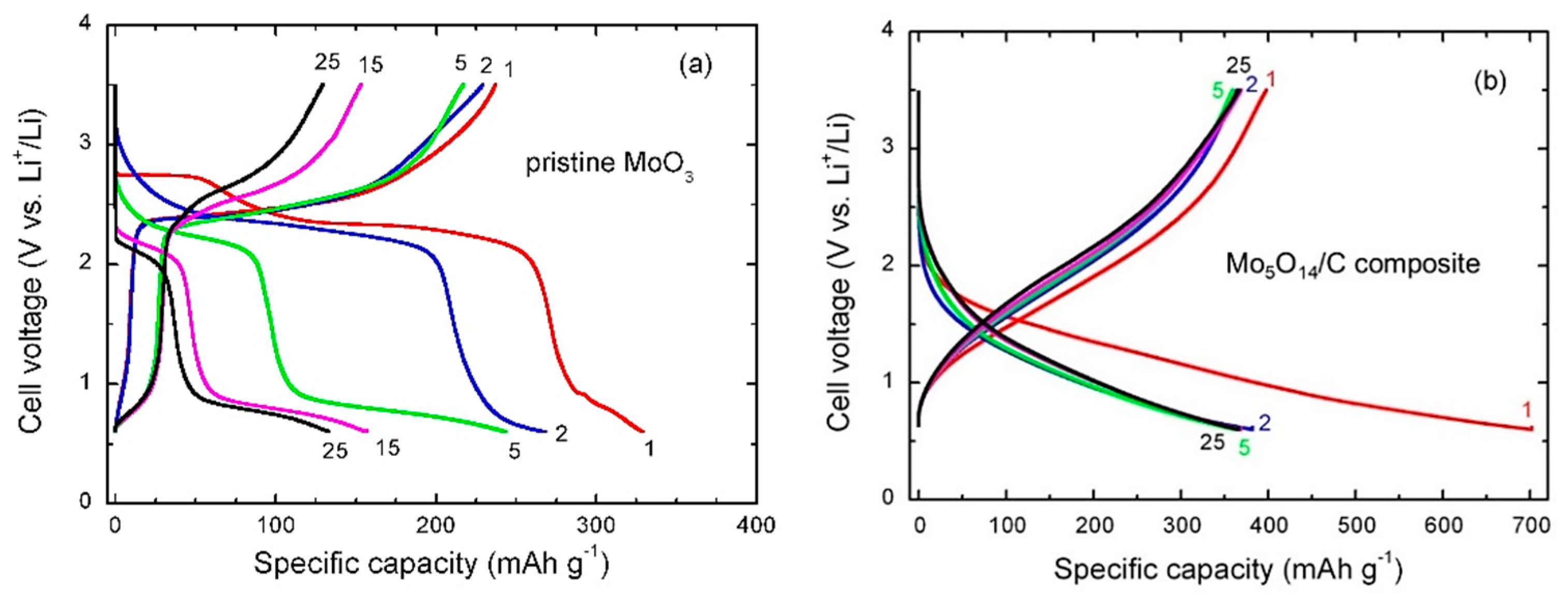
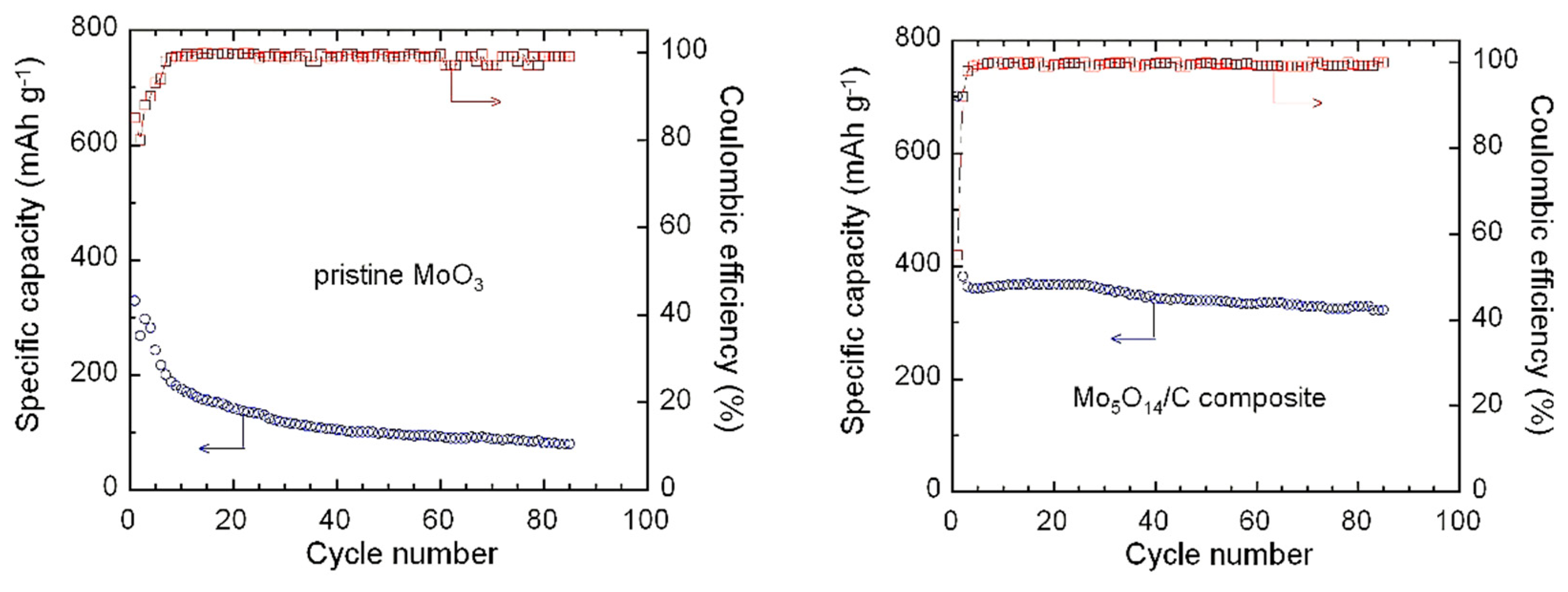
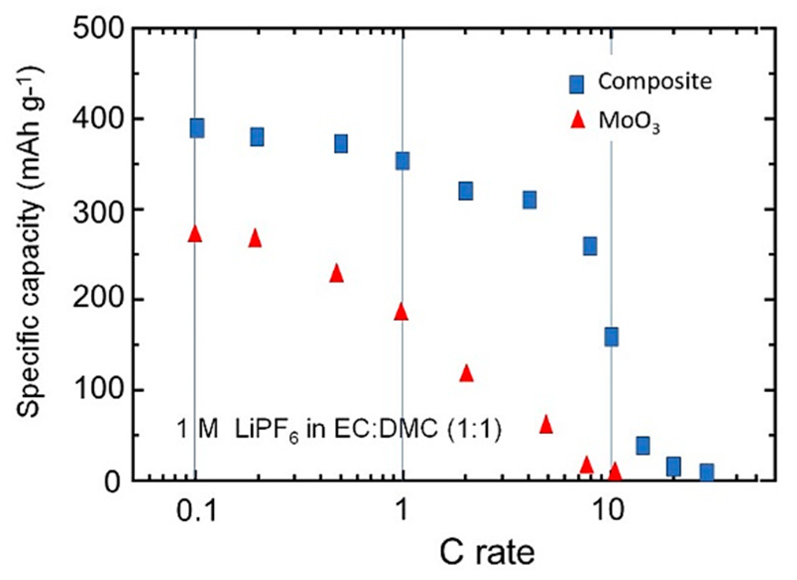
3.3. Electrochemical Properties

The cyclic voltammetry (CV) behavior for pristine MoO3 and Mo5O14/C composite electrodes performed in the potential range 0.6–3.5 V vs. Li+/Li at the scanning rate of 0.05 mV s−1 are displayed in Figure 6a,b, respectively. The choice of the low voltage cut-off of 0.6 V was intentional because of the formation of metallic Mo and 3Li2O, which takes place as a plateau at around 0.4–0.5 V upon further Li+ insertion [37,38]. The CV curves of pristine MoO3 exhibit well-defined redox peaks, due to the fact that this material is well-crystallized. In the first cycle, there are two strong cathodic peaks at ca. 2.7 and 2.3 V, with one reversible anodic peak around 2.6 V. The cathodic peak at 2.7 V is irreversible and disappeared after the first lithiation during subsequent cycles (Figure 6a). Such a behavior has been evidenced by preparing pre-lithiated LixMoO3 samples using the chemical insertion by LiI in the range 0.1 ≤ x ≤ 1.0. For x ≈ 0.49, the CV curve displays only one reversible redox couple that is an indication of the disappearance of the pure α-MoO3 phase with similar patterns for subsequent cycles [39]. The mesoporous Mo5O14/C composite reveals a featureless voltammetry response over a broad potential range; this pattern arises from its amorphous-like structure, which leads to numerous insertion sites for Li+ ions. After the first cycle, a high reversibility is observed from overlapping CV curves (Figure 6b.)
Figure 7a,b present the galvanostatic charge-discharge (GCD) profiles of the pristine MoO3 and Mo5O14/C composite electrodes, respectively, recorded at C/10 rate (70 mA g−1). In a fresh cell, pristine MoO3 and Mo5O14/C composite are electrodes in a “charged state” with all Mo ions with the 6+ oxidation state. Thus, the first process of lithiation occurs during discharge (reduction of Mo to 5+ and 4+ states) providing a capacity Q. During the subsequent charge Q’, Mo is oxidized, but not all Li ions can be extracted from the lithiated phase, thus less electrons are transferred and Q’<Q. Definitely, the electrochemical behaviors of these electrodes are different. The difference between the shape of charge/discharge curves of pristine MoO3 and Mo5O14/C is mainly due to the difference in the structure and morphology of the active material. In contrast with the 2D structure of α-MoO3, Mo5O14 has a 3D structure with empty site in the tunnels inducing a different Gibbs energy that results in unlike voltage profile. In addition, the voltage profile of an amorphous material is a S-shape curve due to the random distribution of the available site in the framework.
In the first discharge process, the crystallized pristine MoO3 shows two typical plateaus (Figure 7a), in accordance with the cathodic peaks in the CV curve (Figure 6a). The insertion of lithium proceeds in two steps at 2.75 and 2.30 V vs. Li+/Li within the capacity range of 0–50 and 100–250 mAh g−1, respectively. The disappearance of the first plateau at the second cycle is related to an irreversible structural change, suggesting that part of Li+ ions cannot be extracted during the charge process. This structural modification has been described by the phase transition from MoO3 to LixMoO3 (where x ≤ 0.25), which induces a pronounced expansion of the interlayer spacing (from 0.69 to 1.175 nm) [39,40]. Similar behavior was previously observed for lithium intercalation in the layered V2O5 host [41]. The specific capacity of the P-MoO3 electrode decreases continuously over subsequent discharge-charge cycles from 330 mAh g−1 (1st cycle) to 136 mAh g−1 (25th cycle). This large capacity loss (2% per cycle) reveals the poor electrochemical stability of the α-MoO3 phase prepared by citrate-gel method. In contrast, the mesoporous Mo5O14/carbon composite exhibits better electrochemical performance. GCD curves are featureless (without plateau) showing a steady decay of the cell voltage upon Li insertion. Such discharge-charge profiles are characteristic of an amorphous phase, which implies a wide variation in energy for the Li sites available for insertion [42,43]. For the first discharge, this electrode delivers a specific capacity of 703 mAh g−1, decreasing to 388 mAh g−1 at the 2nd cycle. During next cycles, the discharge capacities slightly decrease to reach 325 mAh g−1 at the 50th cycle. The cyclability of pristine MoO3 and Mo5O14/C composite electrodes was tested at C/10 rate in the cell voltage range of 0.6–3.5 V as shown in Figure 8. The Mo5O14/C composite shows an almost stable electrochemical behavior up to 85 cycles with a rate of capacity fade of 0.8% per cycle. Results of the rate capability are presented in Figure 9. The high performance of the Mo5O14/C composite is clearly revealed with a specific discharge capacity of 155 mAh g−1 at 10C rate (7 A g−1).

4. Discussion

The structural and electrochemical properties of a composite formed of oxygen-deficient MomO3m−1 and carbon have been examined for the first time. MomO3m−1 compounds are particularly interesting, mainly due to the structure with large tunnels accessible for Li+ ions. In addition, they have a high electrical resistivity, i.e., ρ = 1 Ω cm for Mo8O23 and ρ = 78 Ω cm−1 for Mo18O52 that are semiconductors, while η-Mo4O11 is metallic with ρ = 1.7 10−4 Ω cm [44]. In the work presented here, the reduction of the layered structure MoO3 obtained by the decomposition of citric acid as chelating agent and ammonium molybdate tetrahydrate as raw material has been performed in closed atmosphere. The as-prepared mesoporous Mo5O14/C composite was successfully obtained by a moderate annealing temperature of 500 °C. This new material is composed of a honeycomb carbon matrix, in which amorphous Mo5O14 nanoparticles are introduced. It is assumed that the Mo6+ ions were reduced by the presence of CO, CO2 and NH3 gases coming from the chelate and raw material forming the non-stoichiometric (oxygen-deficient) Mo5O14/C compound. This tunnel-like structure accommodates oxygen deficiency via oxygen vacancies and crystallographic shear planes. The formation of an intermediate compound MomO3m−1 between MoVIO3 and MoIVO2 during the reduction of MoO3 has been reported many times [15,45,46], but here, despite the previous claims, we obtained a stable phase with the O/Mo ratio of 2.8.
Also, this work illustrates the synergy between a molybdenum oxide and carbon that exhibits excellent electrochemical performance of the composite. Also, it reveals the importance of electronic conductivity and the mesoporous nature for substantial lithium insertion in tunnel-like molybdenum-oxide compounds. In contrast to the large capacity fade due to the interlayer spacing expansion in crystalline α-MoO3, the excellent electrochemical behavior of the Mo5O14/C composite electrode is due to the formation of large mesopores. The unique cycling performance of the composite is attributed to the presence of carbon, which plays a dual role in enwrapping the tunnel-like Mo5O14 nanoparticles and accommodating the volume change. Graphitized carbon provides a large contact surface and acts as an excellent conductive agent facilitating the charge-discharge process. The porosity formed by carbon facilitates the transport of charge carriers and the delocalized insertion site in the amorphous matrix enhances the kinetics of Li+ ions. According to its high reversible capacity and good cycling stability, the Mo5O14/C composite is a promising alternative electrode material for application in lithium-ion batteries.
Several studies have demonstrated the improved cycling performance of oxygen-deficient MomO3m−1 compounds compared with stoichiometric MoO3. In an early work, Besenhard and Schöllhorn [4] have shown that discharge-charge reactions of Mo18O52 and Mo8O23 electrodes in organic Li+ electrolytes occur via reversible topotactic redox processes. Cignini et al. examined the performance of various non-stoichiometric MomO3m−1 compounds as cathodes in Li cells, i.e., Mo8O23, Mo9O26, Mo17O47 and Mo4O11 and showed that Mo5O14 can deliver a specific capacity of 310 mA g−1 when discharged at 0.5 mA cm−2 in the voltage range 2.5–1.0 V [5]. Christian and co-workers [9] reported that for the oxides Mo4O11 (MoO2.75), Mo17O47 (MoO2.765), Mo8O23 (MoO2.889), and Mo9O26 (MoO2.875) the highest reversible capacity (1.5Li/Mo) was obtained for Mo17O47 after several deep discharge-charge cycles in the potential range 2.9–1.4 V. The reversible capacities of other MomO3m−1 compounds are considerably less than that of Mo17O47 except for Mo4O11, which exhibits a reversible capacity of 0.75Li/Mo after 20 deep cycles. These results suggest that both channel/site size and electronic conductivity are the predominant factors influencing the extent of reversible Li insertion by MomO3m−1 oxides with tunneled framework. Distortions and nonequivalence of the available sites should also affect the thermodynamics of the reduction processes. Julien et al. showed that the first discharge profile of a crystalline LixMoO2.8 (lithiated Mo5O14) displays a stepped behavior with a voltage plateau at ca. 2.2 V followed by a potential decline for x > 0.7Li/Mo and a total Li uptake of 1.45Li/Mo for a cut-off voltage of 1.0 V. For all Mo ions reduced to Mo4+, the expected lithium uptake would be 8/5(1.6) Li/Mo; a value close to 258 mAh g−1 measured by electrochemical titration [11]. Jung et al. [14] showed that during the first discharge, MoO2.895 prepared by ball milling delivered a specific of ca. 600 mAh g−1 that decreased to 420 mAh g−1 (2nd cycle) in the voltage range 3.5–0.5 V. For comparison, electrochemical properties of composites formed by a Mo oxide and a carbonaceous material are listed in Table 2.
According to the GCD profile presented in Figure 7b, the initial discharge capacity and the initial Coulombic efficiency of the Mo5O14/C composite are 703 mAh g−1 and 55%, respectively. In the same voltage range, a composite electrode made of MoO3 nanocrystals distributed in an amorphous carbon matrix delivered a specific capacity of approximately 630 mAh g−1 and an initial Coulombic efficiency of 75% [47]. An initial discharge capacity of approximately 550 mAh g−1 with a Coulombic efficiency of 69% was reported for crumpled graphene–MoO3 composite cycled at a constant current density of 2 A g−1 [22]. Furthermore, the higher performance of the Mo5O14-type/C composite electrode is attributed to the accommodated volume expansion. Christian et al. [9] have shown that the unit cell of the fully lithiated Mo5O14 crystal expands in the b direction and contracts in both the a and c directions upon insertion of lithium. Also, we believe that the presence of 26 wt.% carbon homogeneously distributed and associated with the intrinsic properties of the active particles minimizes the volume expansion.

5. Conclusions

Pure α-MoO3 and mesoporous Mo5O14-type/C composite were successfully prepared by a citrate–gel method from ammonium molybdate precursor. Crystalline orthorhombic α-MoO3 is observed for xerogel calcined in air, while the Mo5O14/C composite is prepared under argon atmosphere. The latter one is a poorly crystalline material that is composed of Mo5O14 nanograins incorporated into a carbon matrix as noticed from X-ray diffraction and Raman spectroscopy. The carbon content of approximately 26 wt.% was estimated from TGA and elemental analysis. Analysis of the vibrational features of D- and G- Raman bands of the carbon reveals that it is moderately graphitized. BET measurements show that the Mo5O14/C composite exhibits a surface area of 7.1 m2 g−1, average pore size of approximately 4 nm and total pore volume of 0.07 cm3 g−1, which are favorable for enhanced electrochemical insertion of Li+ ions into the mesoporous lattice.
The Mo5O14/C composite appears to be electrochemically stable showing a specific capacity of 325 mAh g−1 and a capacity fade of 0.8% after 50 cycles at 0.1C. Such a good performance is attributed to the mesoporous nature of the electrode material and the presence of carbon, which suppresses the aggregation of molybdenum-oxide particles and thus increases their structural stability during cycling, while keeping the particles electrically connected.

Author Contributions

Conceptualization, A.M.H.; investigation, A.E.A.-G. and R.S.E.-T.; writing—original draft, C.M.J.; writing—review and editing, A.M., H.E. and S.I.; supervision, H.E. All authors have read and agreed to the published version of the manuscript.

Funding

This research received no external funding.

Acknowledgments

A.M.H and A.E.A acknowledge the partial support by National Research Centre through inhouse project.

Conflicts of Interest

The authors declare no conflict of interest.

References

  1. Julien, C.M.; Mauger, A.; Vijh, A.; Zaghib, K. Lithium Batteries: Science and Technology; Springer: Cham, Switzerland, 2016. [Google Scholar]
  2. Scanlon, D.O.; Watson, G.W.; Payne, D.J.; Atkinson, G.R.; Egdell, R.G.; Law, D.S.L. Theoretical and experimental study of the electronic structures of MoO3 and MoO2. J. Phys. Chem. C 2010, 114, 4636–4645. [Google Scholar] [CrossRef]
  3. Kihlborg, L. Studies on molybdenum oxides. Acta Chem. Scand. 1959, 13, 954–962. [Google Scholar] [CrossRef]
  4. Besenhard, J.O.; Schollhorn, R. The discharge reaction mechanism of the MoO3 electrode in organic electrolytes. J. Power Sources 1976, 1, 267–276. [Google Scholar] [CrossRef]
  5. Cignini, P.; Icovi, M.; Panero, S.; Pistoia, G.; Temperoni, C. Non-stoichiometric molybdenum oxides as cathodes for lithium cells. Part. I. Primary batteries. J. Electroanal. Chem. 1979, 102, 333–342. [Google Scholar] [CrossRef]
  6. Icovi, M.; Panero, S.; D’Agate, A.; Pistoia, G.; Temperoni, C. Non-stoichiometric molybdenum oxides as cathodes for lithium cells. Part. II. Secondary batteries. J. Electroanal. Chem. 1979, 102, 343–349. [Google Scholar] [CrossRef]
  7. Pistoia, G.; Temperoni, C.; Cignini, P.; Icovi, M.; Panero, S. Non-stoichiometric molybdenum oxides as cathodes for lithium cells. Part. III. Cells based on Mo18O52. J. Electroanal. Chem. 1980, 108, 169–180. [Google Scholar] [CrossRef]
  8. Fiordiponti, P.; Pistoia, G.; Temperoni, C.; Icovi, M.; Panero, S. Non-stoichiometric molybdenum oxides as cathodes for lithium cells. Part. IV. Factors influencing the performance of Li/Mo8O23 batteries. J. Electroanal. Chem. 1980, 108, 181–190. [Google Scholar] [CrossRef]
  9. Christian, P.A.; Carides, J.N.; DiSalvo, F.J.; Waszczak, J.V. Molybdenum oxide cathodes in secondary lithium cells. J. Electrochem. Soc. 1980, 127, 2315–2319. [Google Scholar] [CrossRef]
  10. Nazri, G.-A.; Julien, C. Studies of lithium intercalation in heat-treated products obtained from molybdic acid. Ionics 1996, 2, 1–6. [Google Scholar] [CrossRef]
  11. Julien, C.; Yebka, B. Electrochemical Features of Lithium Batteries Based on Molybdenum-Oxide Compounds. In Materials for Lithium Batteries; Julien, C., Stoynov, Z., Eds.; Springer Science: Dordrecht, The Netherlands, 2000; pp. 263–277. [Google Scholar]
  12. Mondal, A.K.; Chen, S.; Liu, D.S.H.; Wang, G. Fabrication and enhanced electrochemical performances of MoO3/graphene composite as anode material for lithium-ion batteries. Inter. J. Smart Grid Clean Energy 2014, 3, 142–148. [Google Scholar] [CrossRef]
  13. Gao, B.; Fan, H.; Zhang, X. Hydrothermal synthesis of single crystal MoO3 nanobelts and their electrochemical properties as cathode electrode materials for rechargeable lithium batteries. J. Phys. Chem. Solids 2012, 73, 423–429. [Google Scholar] [CrossRef]
  14. Jung, Y.S.; Lee, S.; Ahn, D.; Dillon, A.C.; Lee, S.-H. Electrochemical reactivity of ball-milled MoO3-y as anode materials for lithium-ion batteries. J. Power Sources 2009, 188, 286–291. [Google Scholar] [CrossRef]
  15. Hashem, A.M.; Abbas, S.M.; Abdel-Ghany, A.E.; Eid, A.E.; Abdel-Khalek, A.A.; Indris, S.; Ehrenberg, H.; Mauger, A.; Julien, C.M. Blend formed by oxygen deficient MoO3-δ oxides as lithium-insertion compounds. J. Alloys Compd. 2016, 686, 744–752. [Google Scholar] [CrossRef] [Green Version]
  16. Xia, Q.; Zhao, H.; Du, Z.; Zeng, Z.; Gao, C.; Zhang, Z.; Du, X.; Kulka, A.; Swierczek, K. Facile synthesis of MoO3/carbon nanobelts as high-performance anode material for lithium ion batteries. Electrochim. Acta 2015, 180, 947–956. [Google Scholar] [CrossRef]
  17. Liu, C.-L.; Wang, Y.; Zhang, C.; Li, X.-S.; Dong, W.-S. In situ synthesis of α-MoO3/graphene composites as anode materials for lithium ion battery. Mater. Chem. Phys. 2014, 143, 1111–1118. [Google Scholar] [CrossRef]
  18. Feng, C.; Gao, H.; Zhang, C.; Guo, Z.; Liu, H. Synthesis and electrochemical properties of MoO3/C nanocomposite. Electrochim. Acta 2013, 93, 101–106. [Google Scholar] [CrossRef]
  19. Xia, Q.; Zhao, H.; Du, Z.; Wang, J.; Zhang, T.; Wang, J.; Lv, P. Synthesis and electrochemical properties of MoO3/C composite as anode material for lithium-ion batteries. J. Power Sources 2013, 226, 107–111. [Google Scholar] [CrossRef]
  20. Thomas, T.; Jiji, J.; Joy, L.; Mathew, A.; Reshmi, R. Hydrothermal synthesis MoO3-GO nano composites for energy storage application. AIP Conf. Proc. 2019, 2082, 060002. [Google Scholar]
  21. Cao, X.; Zheng, B.; Shi, W.; Yang, J.; Fan, Z.; Luo, Z.; Rui, X.; Chen, B.; Yan, Q.; Zhang, H. Reduced graphene oxide-wrapped MoO3 composites prepared by using metal–organic frameworks as precursor for all-solid-state flexible supercapacitors. Adv. Mater. 2015, 27, 4695–4701. [Google Scholar] [CrossRef]
  22. Choi, S.H.; Kang, Y.C. Crumpled graphene–molybdenum oxide composite powders: Preparation and application in lithium-ion batteries. ChemSusChem 2014, 7, 523–528. [Google Scholar] [CrossRef]
  23. Tao, T.; Glushenkov, A.M.; Zhang, C.F.; Zhang, H.Z.; Zhou, D.; Guo, Z.P.; Liu, H.K.; Chen, Q.Y.; Hu, H.P.; Chen, Y. MoO3 nanoparticles dispersed uniformly in carbon matrix: A high capacity composite anode for Li-ion batteries. J. Mater. Chem. 2011, 21, 9350–9355. [Google Scholar] [CrossRef]
  24. Kihlborg, L. Stabilization of the tunnel structure of Mo5O14 by partial metal atom substitution. Acta Chem. Scand. 1969, 23, 1834–1835. [Google Scholar] [CrossRef]
  25. Ekström, T. Formation of ternary phases of Mo5O14 and Mo17O47 structure in the molybdenum-wolfram-oxygen system. Mater. Res. Bull. 1972, 7, 19–26. [Google Scholar] [CrossRef]
  26. Knobl, S.; Zenkovets, G.A.; Kryukova, G.N.; Ovsitser, O.; Niemeyer, D.; Schlögl, R.; Mestl, G. The synthesis and structure of a single-phase, nanocrystalline MoVW mixed oxide catalyst of the Mo5O14 type. J. Catal. 2003, 215, 177–187. [Google Scholar] [CrossRef]
  27. Phillips, B.; Chang, L.Y. Condensed-phase relations in the system Mo-O. Trans. Met. Soc. AIME 1965, 233, 1433–1436. [Google Scholar]
  28. Nazri, G.-A.; Julien, C. Far-infrared and Raman studies of orthorhombic MoO3 single crystal. Solid State Ionics 1992, 53–56, 376–382. [Google Scholar] [CrossRef]
  29. Dieterle, M.; Mestl, G. Raman spectroscopy of molybdenum oxides. Part II. Resonance Raman spectroscopic characterization of the molybdenum oxides Mo4O11 and MoO2. Phys. Chem. Chem. Phys. 2002, 4, 822–826. [Google Scholar] [CrossRef]
  30. Balendhran, S.; Deng, J.; Ou, J.Z.; Walia, S.; Scott, J.; Tang, J.; Wang, K.L.; Field, M.R.; Russo, S.; Zhuiykov, S.; et al. Enhanced charge carrier mobility in two-dimensional high dielectric molybdenum oxide. Adv. Mater. 2013, 25, 109–114. [Google Scholar] [CrossRef]
  31. Nazri, G.A.; Julien, C. Heat-treatment studies of molybdenum oxide-monohydrate. Solid State Ionics 1995, 80, 271–275. [Google Scholar] [CrossRef]
  32. Hardcastle, F.D.; Wachs, I.E. Determination of molybdenum-oxygen bond distances and bond orders by Raman spectroscopy. J. Raman Spectrosc. 1990, 21, 683–691. [Google Scholar] [CrossRef]
  33. Subrahmanyam, K.S.; Vivekchand, S.R.C.; Govindaraj, A.; Rao, C.N.R. A study of graphenes prepared by different methods: Characterization, properties and solubilization. J. Mater. Chem. 2008, 18, 1517–1523. [Google Scholar] [CrossRef]
  34. Hu, Z.H.; Srinivasan, M.P.; Ni, Y.M. Preparation of mesoporous high surface area activated carbon. Adv. Mater. 2000, 12, 62–65. [Google Scholar] [CrossRef]
  35. Rodriguez-Reinoso, F.; Molina-Sabio, M. Activated carbons from lignocellulosic materials by chemical and/or physical activation: An overview. Carbon 1992, 30, 1111–1118. [Google Scholar] [CrossRef]
  36. Barrett, E.P.; Joyner, L.G.; Halenda, P.P. The determination of pore volume and area distributions in porous substances. I. Computations from nitrogen isotherms. J. Am. Chem. Soc. 1951, 73, 373–380. [Google Scholar] [CrossRef]
  37. Sun, Y.X.; Wang, J.; Zhao, B.; Cai, R.; Ran, R.; Shao, Z.P. Binder-free α-MoO3 nanobelt electrode for lithium-ion batteries utilizing van der Waals forces for film formation and connection with current collector. J. Mater. Chem. A 2013, 1, 4736–4746. [Google Scholar] [CrossRef]
  38. Wang, Z.Y.; Madhavi, S.; Lou, X.W. Ultralong α-MoO3 nanobelts: Synthesis and effect of binder choice on their lithium storage properties. J. Phys. Chem. C 2012, 116, 12508–12513. [Google Scholar] [CrossRef]
  39. Hashem, A.M.; Askar, M.H.; Winter, M.; Albering, J.H.; Besenhard, J.O. Two-phase reaction mechanism during chemical lithium insertion into α-MoO3. Ionics 2007, 13, 3–8. [Google Scholar] [CrossRef]
  40. Li, W.Y.; Cheng, F.Y.; Tao, Z.L.; Chen, J. Vapor-transportation preparation and reversible lithium intercalation/deintercalation of alpha-MoO3 microrods. J. Phys. Chem. B 2006, 110, 119–124. [Google Scholar] [CrossRef]
  41. Leroux, F.; Loene, B.E.; Nazar, L.F. Electrochemical lithium intercalation into a polyaniline/V2O5 nanocomposite. J. Electrochem. Soc. 1996, 143, L181–L183. [Google Scholar] [CrossRef]
  42. Dong, W.; Mansour, A.N.; Dunn, B. Structural and electrochemical properties of amorphous and crystalline molybdenum oxide aerogels. Solid State Ionics 2001, 144, 31–40. [Google Scholar] [CrossRef]
  43. Brezesinski, T.; Wang, J.; Tolbert, S.H.; Dunn, B. Ordered mesoporous α-MoO3 with iso-oriented nanocrystalline walls for thin-film pseudo capacitors. Nat. Mater. 2010, 9, 146–151. [Google Scholar] [CrossRef] [PubMed]
  44. Gruber, H.; Krautz, E. Untersuchungen der elektrischen leifähigkeit und des magnetowiderstandes im system molydän-sauerstoff. Phys. Status Solidi A 1980, 62, 615–624. [Google Scholar] [CrossRef]
  45. Aso, I.; Nakao, M.; Yamazoe, N.; Seiyama, T. Study of metal oxide catalysts in the olefin oxidation from their reduction behavior. 1. Reduction of various metal oxides with propylene. J. Catal. 1979, 57, 287–295. [Google Scholar] [CrossRef]
  46. Yi, Y.; An, H.; Zhang, P.; Tian, X.; Yang, P.; Liu, P.; Wang, T.; Qu, L.; Li, M.; Yang, G.; et al. Oxygen deficiency driven conversion of polysulfide by electrocatalysis: MoO3-x nanobelts for an improved lithium-sulfur battery cathode. ChemNanoMat 2019, 5, 926–931. [Google Scholar] [CrossRef]
  47. Cho, J.S. Large scale process for low crystalline MoO3-carbon composite microspheres prepared by one-step spray pyrolysis for anodes in lithium-ion batteries. Nanomaterials 2019, 9, 539. [Google Scholar] [CrossRef] [Green Version]
  48. Lu, W.; Chen, X.; Xue, M.; Cui, Y.; Zhuang, Q. Ultrasonic synthesis of α-MoO3 Nanobelt@CNTs composite for lithium battery and its electrochemical performances. Int. J. Electrochem. Sci. 2018, 13, 275–286. [Google Scholar] [CrossRef]
  49. Ni, J.F.; Wang, G.; Yang, J.; Gao, D.; Chen, J.; Gao, L.; Li, Y. Carbon nanotube-wired and oxygen-deficient MoO3 nanobelts with enhanced lithium-storage capability. J. Power Sources 2014, 247, 90–94. [Google Scholar] [CrossRef]
  50. Wu, D.; Shen, R.; Yang, R.; Ji, W.; Jiang, M.; Ding, W.; Peng, L. Mixed molybdenum oxides with superior performances as an advanced anode material for lithium-ion batteries. Sci. Rep. 2017, 7, 44697. [Google Scholar] [CrossRef]
Scheme 1. Overall synthesis process of the crystalline MoO3 and MomO3m−1/C composite.
Nanomaterials 10 00008 sch001
Figure 1. XRD pattern of (a) Mo5O14/C composite compared with the diagram of Mo5O14 as reference [26] and (b) crystalline a-MoO3 (orthorhombic structure).
Nanomaterials 10 00008 g001
Figure 2. TGA and DSC curves of the MoO3 synthesis (a) and as prepared P-MoO3 (b) and Mo5O14/C composite (c) recorded at heating rate of 10 °C min1.
Nanomaterials 10 00008 g002
Figure 3. SEM images of P-MoO3 (a,b) and Mo5O14/C composite (c,d) synthesized by sol-gel method assisted by citric acid as chelating agent.
Nanomaterials 10 00008 g003
Figure 4. Raman spectra of the α-MoO3 (a) and Mo5O14/C composite (b) synthesized by sol-gel method assisted by citric acid as chelating agent. This spectrum was recorded at a spectral resolution of 2 cm−1 using the 514.5 nm laser line.
Nanomaterials 10 00008 g004
Figure 5. N2 adsorption-desorption isotherms (a) and pore size distribution (b) for P-MoO3 and Mo5O14/C composite.
Nanomaterials 10 00008 g005
Figure 6. CV curves of the initial five cycles for P-MoO3 (a) and Mo5O14/C composite (b) recorded at the scanning rate of 0.05 mV s−1.
Nanomaterials 10 00008 g006
Figure 7. Typical galvanostatic charge-discharge curves of P-MoO3 (a) and Mo5O14/C composite (b) electrodes. Experiments were performed in 1 mol L−1 LiPF6/EC:DMC electrolyte at C/10 rate (70 mA g−1).
Nanomaterials 10 00008 g007
Figure 8. Cycling performance of pristine MoO3 and Mo5O14/C composite electrodes. Cells were tested at C/10 rate using 1 mol L−1 LiPF6/EC:DMC electrolyte.
Nanomaterials 10 00008 g008
Figure 9. Rate capability of pristine MoO3 and Mo5O14/C composite electrodes.
Nanomaterials 10 00008 g009
Table 1. Results of the BET experiments P-MoO3 and Mo5O14-type/C composite.
SampleBET Surface Area (m2 g−1)Total Pore Volume (cm3 g−1)Average Pore Size (nm)
P-MoO34.50.00242.19
Mo5O14-type/C7.10.07194.01
Table 2. Electrochemical properties of composites formed by Mo oxides and carbonaceous materials. Initial discharge specific capacities are obtained at a cut-off of 0.6 V vs. Li+/Li.
Composite (a)Cathode Loading (mg cm−2)Specific Capacity (mAh g−1)Current RateRef.
MoO3/a-C1.56301 A g−1[47]
MoO3/CNTs (b)-300C/5[48]
MoO3/C-~60040 mA g−1[18]
Mo3O8/CNTs-~45080 mA g−1[49]
Carbon-free MMO (c)-3000.1 A g−1[50]
MoO3/C-~4200.2C[23]
MoO3/27 wt.% Gr-~45050 mA g−1[17]
MoO3/47 wt.% Gr-~48050 mA g−1[17]
MoO3/C1.5~3500.1 A g−1[19]
MoO3/Gr1.2~5502 A g−1[22]
Mo5O14/C2.1703C/10this work
(a) CNTs: carbon nanotubes; rGO: reduced graphene oxide; Gr: graphene; a-C: amorphous carbon. (b) Voltage range of 3.5–1.5 V vs. Li+/Li; (c) MMO (MoO2.63) is a mixture of MoO3+MoO2+Mo4O11.

