Article

Biomechanical Effects of Horizontal, Vertical, and Combined Misfits in Full-Arch Implant-Supported Titanium Frameworks: A Three-Dimensional Finite Element Analysis


by
Hale Arikan Kalayci
1,* and
Mustafa Baris Guncu
2
1
Department of Prosthodontics, Faculty of Dentistry, Başkent University, Ankara 06790, Turkey
2
Department of Prosthodontics, Faculty of Dentistry, Hacettepe University, Ankara 06100, Turkey
*
Author to whom correspondence should be addressed.
J. Funct. Biomater. 2026, 17(9), 478; https://doi.org/10.3390/jfb17090478 (registering DOI)
Submission received: 5 August 2026 / Revised: 9 September 2026 / Accepted: 16 September 2026 / Published: 19 September 2026
(This article belongs to the Section Dental Biomaterials)

Abstract

This study evaluated the effects of misfit type, magnitude, and location on the stress distribution in full-arch screw-retained implant frameworks. A maxillary finite element model with four implants was analyzed under 16 scenarios, characterized by horizontal misfits of 10, 50, 100, and 200 µm; vertical misfits of 10 and 100 µm; and combined 10–10 and 100–100 µm misfits, each positioned anteriorly or posteriorly. Forced seating was simulated using prescribed displacement; no occlusal load or screw preload was applied. Von Mises stresses were evaluated in the framework, occlusal screws, and implants, and principal stresses were assessed in peri-implant bone. Framework stress increased with horizontal misfit magnitude. When the same numerical misfit value (10 or 100 µm) was applied at the same location under otherwise identical model conditions, vertical misfit produced higher framework stress than horizontal misfit, indicating a direction-dependent response associated with different seating deformation modes. The posterior 100–100 µm combined misfit produced the maximum framework (356 MPa), occlusal screw (193 MPa), and implant (250 MPa) stresses. In contrast, the maximum principal stress peaked at the posterior bone site with the anterior 200 µm horizontal misfit (V0 H200 A; 77 MPa), while the most negative minimum principal stress occurred at the posterior bone site with the posterior 200 µm horizontal misfit (V0 H200 P; −52 MPa). Among the tested scenarios, combined misfits yielded the highest framework and screw stresses, whereas implant and bone responses depended on the magnitude and location of the misfit. These findings indicate that the types, magnitudes, and locations of misfits should be considered during framework-fit assessments, with particular attention to combined misfits, before definitive seating.

1. Introduction

Implant-supported fixed complete dentures show high survival in edentulous patients and, when supported by four implants, may reduce the need for extensive surgery [1,2,3]. Passive fit—the absence of strain in implant components and the framework after screw preload—is considered important for limiting stress, whereas misfit is a dimensional discrepancy at the prosthetic interface [4,5,6,7]. Misfit may contribute to screw loosening or fracture, framework fracture, veneering-material chipping, and increased peri-implant biomechanical demand [4,5,6,7]; it should therefore be minimized before definitive seating.
Although implant outcomes are multifactorial and factors beyond prosthetic fit influence peri-implantitis surgery and late failure [8], misfit is a modifiable factor. Fit can be assessed by visual or tactile inspection, radiography, the one-screw test, microscopy, strain-gauge measurements, and finite element analysis (FEA) [6,9].
Framework discrepancies may be vertical, horizontal, or combined. Research has emphasized vertical gaps because they are more readily quantified microscopically, leaving horizontal effects less understood [10]. Horizontal distortion may also escape conventional vertical-gap assessment [10,11]. The often-cited acceptable range of 10–150 µm lacks strong support [12], and a recent systematic review found insufficient evidence for a universal threshold [5]. That review reported direction- and outcome-dependent ranges: vertical values of 30–160 µm and horizontal values up to 150 µm without mechanical complications, with broader ranges for biological outcomes [5]. These observations guided our directional comparison but were not treated as validated thresholds. Although absolute passivity may be unattainable, even small discrepancies can concentrate stress [13,14,15].
Clinically, considering misfit direction and magnitude may support decisions to accept, adjust, or remake a framework, whereas reliance on a visible vertical gap may overlook horizontal or combined discrepancies. Combined misfit is especially relevant because simultaneous vertical and horizontal components may produce deformation and stress transfer that cannot be predicted from either component alone.
FEA permits controlled isolation of geometric and mechanical variables and component-level stress estimation that is difficult to obtain directly. Rutkunas et al. evaluated vertical misfits of 50–150 µm and horizontal misfits of 35–100 µm in two-implant zirconia frameworks in vitro, whereas full-arch FEAs by Bhering et al. and Dayan and Geckili evaluated implant configuration or framework material without predefined misfit [16,17,18]. Misfit-specific FEAs modeled horizontal displacements of 10–200 µm in a two-implant overdenture bar and terminal gaps of 0–150 µm in a three-implant, five-unit prosthesis [19,20]; a recent two-implant pilot examined a single translational misfit [21]. Thus, evidence for fixed full-arch frameworks remains limited and, to our knowledge, multiple magnitudes of horizontal, vertical, and combined misfit, including lower-range combined discrepancies, have not been systematically compared at anterior and posterior sites within one model. This study therefore quantified the effects of misfit type, magnitude, and location on stresses in a full-arch titanium framework–occlusal screw–implant–bone complex. The null hypothesis was that these factors would not affect von Mises stresses in the framework, occlusal screws, and implants or maximum and minimum principal stresses in peri-implant bone.

2. Materials and Methods

Bone models were reconstructed from Visible Human Project computed tomography (CT) data in Digital Imaging and Communications in Medicine (DICOM) format (U.S. National Library of Medicine, Bethesda, MD, USA); the modeling report specified a reconstruction resolution of 0.33 mm. The DICOM datasets were imported into 3D Slicer (version 5.6; Surgical Planning Laboratory, Brigham and Women’s Hospital, Boston, MA, USA; open-source software) and segmented using appropriate Hounsfield unit thresholds to generate three-dimensional (3D) surface models, which were then exported as standard tessellation language (STL) files. The resulting maxillary models were processed in Blender (version 4.5 LTS; Blender Foundation, Amsterdam, the Netherlands); in particular, all models were aligned and positioned within a common coordinate system in Blender. To reflect the structurally distinct cortical shell and trabecular core of the maxilla, the two bone compartments were modeled separately [22]. A uniform 2 mm inward offset was applied to define the cortical shell, and its internal surface served as the reference for generating the trabecular core. The 2 mm thickness was not selected to reflect patient-specific anatomy but, instead, was adopted as a standardized modeling approximation, as commonly used in dental FEA-based research [23]. Anatomical measurements in edentulous maxillae vary by site and surface (approximately 1.04–2.06 mm), placing 2 mm near the upper end of the reported range [24]; furthermore, cone-beam computed tomography (CBCT) data demonstrate substantial regional variation and thinner mean crestal cortices in the maxilla [22].
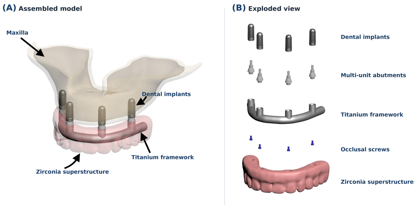
Four implants (Straumann Bone Level, Ø4.1 mm × 10 mm; Institut Straumann AG, Basel, Switzerland) were bilaterally positioned at the maxillary lateral incisor and second premolar sites. All implants were placed axially and parallel to one another; no distal tilt was used. This standardized orientation was maintained across all scenarios in order to isolate the effects of misfit type, magnitude, and location. The implant, multi-unit abutment, occlusal screw, and titanium framework were digitally modeled in Blender, and a 12-unit zirconia fixed dental prosthesis was designed based on the anatomical reference data from Wheeler’s Dental Anatomy Atlas. The assembled model and its components are shown in Figure 1. Scenario-specific framework geometries were generated by introducing predefined discrepancies at selected framework–abutment connections. Horizontal misfit is represented by an internal-wall offset, whereas vertical misfit is represented by a marginal gap; the forced seating procedure is described below. Within the finite element model, all materials were assumed to be homogeneous, isotropic, and linearly elastic. The elastic modulus and Poisson’s ratio were respectively assigned as follows: cortical bone, 13,700 MPa and 0.30; trabecular bone, 1370 MPa and 0.30; and the 12-unit zirconia prosthesis, 200,000 MPa and 0.31 [23]. As a modeling idealization, the implant, multi-unit abutment, occlusal screw, and framework were assigned the same material properties based on commercially pure Grade 4 titanium (elastic modulus, 110,000 MPa; Poisson’s ratio, 0.35) [23,25].
Eight misfit configurations were defined according to their vertical misfit (VM) and horizontal misfit (HM) components: V0 H10, 0 µm VM and 10 µm HM; V10 H0, 10 µm VM and 0 µm HM; V10 H10, 10 µm VM and 10 µm HM; V0 H50, 0 µm VM and 50 µm HM; V0 H100, 0 µm VM and 100 µm HM; V0 H200, 0 µm VM and 200 µm HM; V100 H0, 100 µm VM and 0 µm HM; and V100 H100, 100 µm VM and 100 µm HM. To compare the effects of misfit type, magnitude, and location within the same model, each configuration was evaluated at two anatomical locations, resulting in 16 location-specific scenarios (8 × 2). In subgroup A, misfits were applied at the framework–abutment connections corresponding to bilateral lateral incisor implant sites; in subgroup P, they were applied at connections corresponding to bilateral second premolar implant sites (Table 1).
The selected misfit magnitudes were designed for parametric comparison rather than to represent clinical acceptability thresholds. Regarding the vertical magnitudes, the 10 µm condition represents the lower bound of the commonly cited but unvalidated 10–150 µm range [12], while 100 µm was selected as a representative mid-range value within the reported vertical range. The horizontal series (10, 50, 100, and 200 µm) followed the displacement levels evaluated by Spazzin et al. [19]. The 10 and 100 µm levels were included in both isolated vertical and horizontal conditions to enable matched directional comparisons. In these comparisons, all other model settings remained unchanged. Therefore, the effects of discrepancy orientation and the corresponding seating displacement direction were evaluated, rather than assuming mechanical equivalence between a vertical gap and a horizontal offset. Under the 10–10 and 100–100 µm conditions, the combined application of both components was evaluated. The 200 µm horizontal condition was retained as an exploratory upper-bound scenario; however, a 200 µm VM + 200 µm HM condition fell outside the intended range of the forced-seating analysis and, thus, was not included.
The geometric models were discretized into finite elements to generate the computational meshes. After modeling in Blender, the meshes were prepared for analysis in Altair HyperMesh (version 2024; Altair Engineering, Inc., Troy, MI, USA). Based on the mesh convergence assessment described below, triangular surface elements ranging from 0.10 to 0.25 mm were used, with the finest elements assigned to regions of expected stress concentration. Once all the model surfaces were meshed with these elements, solid meshes of the objects were created using tetrahedral elements. Mesh refinement was concentrated at the framework–abutment interface, implant components, and peri-implant cortical bone, where stress concentrations were expected to occur. Mesh quality was evaluated for all models. Elements exceeding the predefined skewness criterion (>80°) or failing to satisfy the predefined minimum-edge-length criterion were identified during the mesh quality review and corrected before inclusion in the analysis. The HyperMesh models were exported to Altair OptiStruct (version 2024; Altair Engineering, Inc., Troy, MI, USA), a Nastran-based finite element solver. The analyses were performed on an HP workstation (HP Inc., Palo Alto, CA, USA) equipped with an Intel Xeon E-2286 processor (2.40 GHz) and 64 GB of ECC RAM. The documented scenario meshes contained approximately 339,000 nodes and 1.36 million tetrahedral elements (Table 2).
A mesh convergence assessment was performed for the V100 H100 A scenario (100 µm VM + 100 µm HM) using nominal element sizes of 0.4, 0.3, 0.2, and 0.1 mm under otherwise identical boundary, geometric discrepancy, and closure displacement conditions. The peak von Mises stress in the posterior implant was monitored. Successive relative change was calculated as the absolute difference between the updated and preceding values divided by the updated value and multiplied by 100; a value below 3% was defined as indicating convergence.
Adapting the displacement-controlled framework settling approach described by Spazzin et al. [19], forced seating was implemented in four steps. First, separate unseated geometries were generated for the A and P conditions. In the A models, the prescribed discrepancy was introduced symmetrically at both anterior framework–multi-unit abutment connections while the posterior connections remained seated; in the P models, it was introduced symmetrically at both posterior connections while the anterior connections remained seated. Horizontal misfit was created as an offset of 10, 50, 100, or 200 µm between the inner wall of the framework connection and the corresponding external abutment surface. Vertical misfit was created as a 10 or 100 µm gap between the opposing framework and abutment seating surfaces; the combined conditions incorporated both components. Second, the implants and abutments remained in their original positions, and only the framework geometry was altered to establish the unseated configuration. Third, the prescribed displacement was applied directly to nodes on the upper framework surface at both discrepant connections. The horizontal component was equal to the modeled offset and was directed mesio-buccally within the horizontal plane, whereas the vertical component was equal to the modeled gap and was directed along the vertical seating axis toward the intended seated position. Both components were applied concurrently in the combined misfit configurations. Finally, each configuration was analyzed separately in OptiStruct under linear static conditions. No contact constraint was defined at the intentionally discrepant interfaces; thus, the prescribed displacement represents idealized closure of the initial mismatch. No external occlusal load or screw preload was applied.
Nodes on the superior boundary of the bone model were fixed in all three translational directions (Ux = Uy = Uz = 0), thereby preventing rigid-body motion. A symmetric boundary condition was also applied to the nodes of all model components located on the Y–Z symmetry plane: displacement normal to the plane was constrained (Ux = 0), whereas in-plane displacements (Uy and Uz) remained unrestricted. In the global coordinate system, +X and −X represent the buccal and palatal directions, +Y and −Y the posterior and anterior directions, and +Z and −Z the gingival and occlusal directions, respectively. Sixteen linear static analyses were performed using the same boundary conditions and the scenario-specific geometric discrepancy and closure displacement conditions. All other initially contacting component interfaces were assigned FREEZE contact, corresponding to bonded conditions that prevent separation and sliding at those interfaces. Together with the prescribed displacement at the misfit site, this idealization provided a common closure endpoint across scenarios. The displacement-controlled approach was selected to isolate the effects of misfit type, magnitude, and location within a standardized seating protocol, while all other model conditions were held constant. A torque-driven tightening simulation would require additional, history-dependent inputs and assumptions, including frictional contact, torque-to-preload conversion, and tightening sequence, which are beyond the scope of this study. Accordingly, the prescribed displacement represents an idealized final closure configuration rather than screw-generated preload. Each location-specific scenario was solved once. As the analyses were deterministic and did not involve repeated observations, no inferential statistical analysis was performed; as such, the results are compared descriptively.

3. Results

Peak posterior-implant von Mises stress increased from 120 MPa at 0.4 mm to 146 MPa at 0.1 mm. The relative change between the 0.2 and 0.1 mm meshes was 2.5%, meeting the predefined <3% convergence criterion; accordingly, a minimum element size of 0.1 mm was retained.
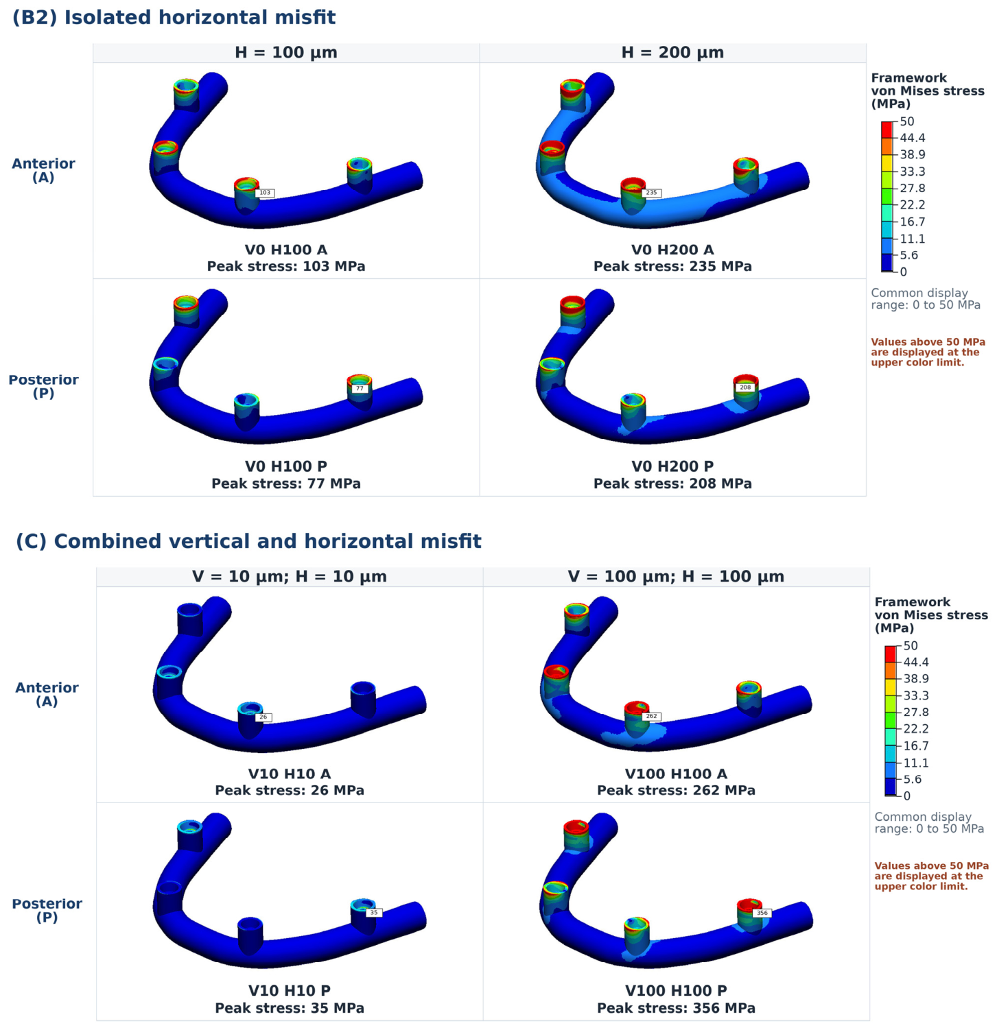
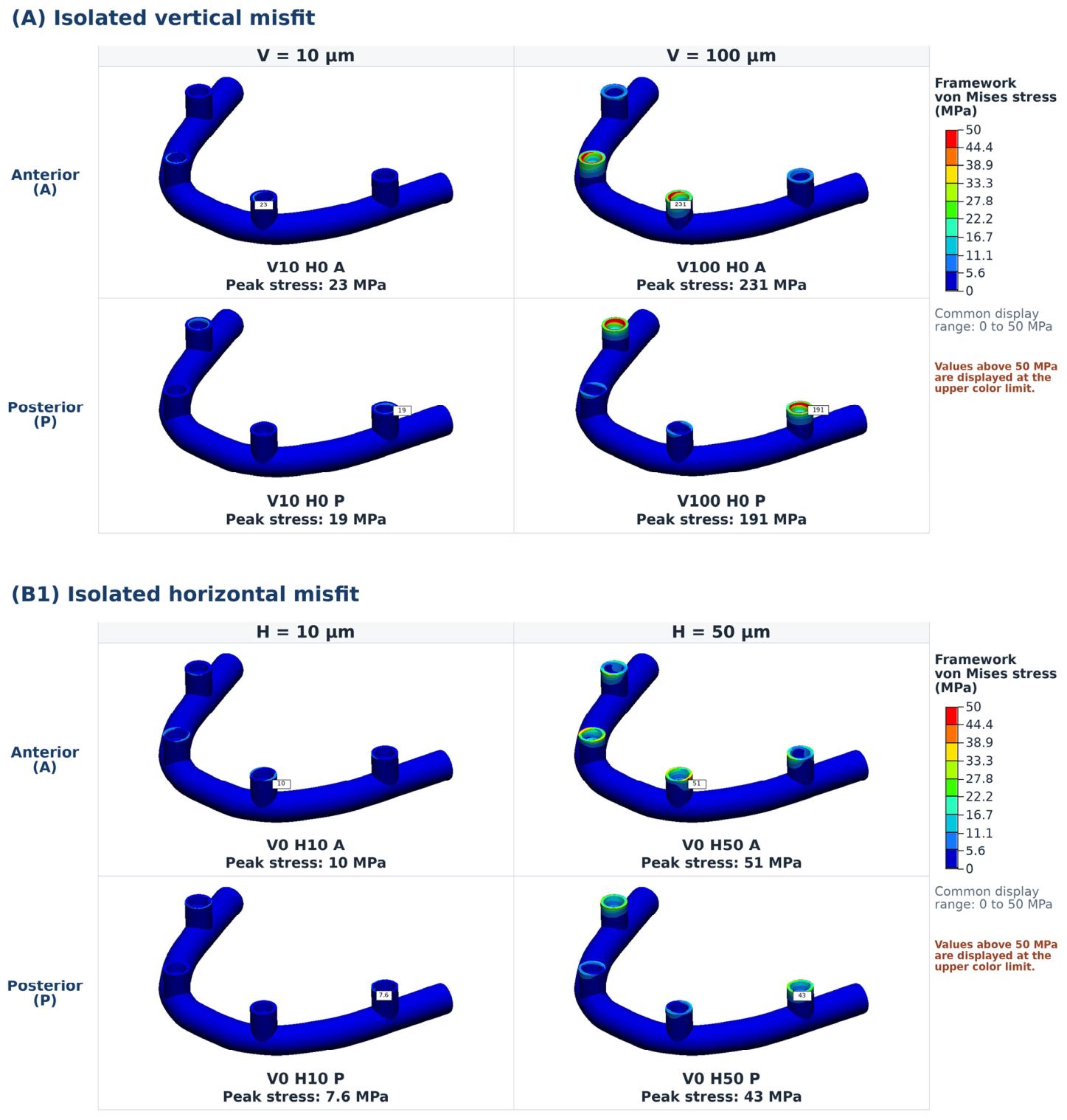
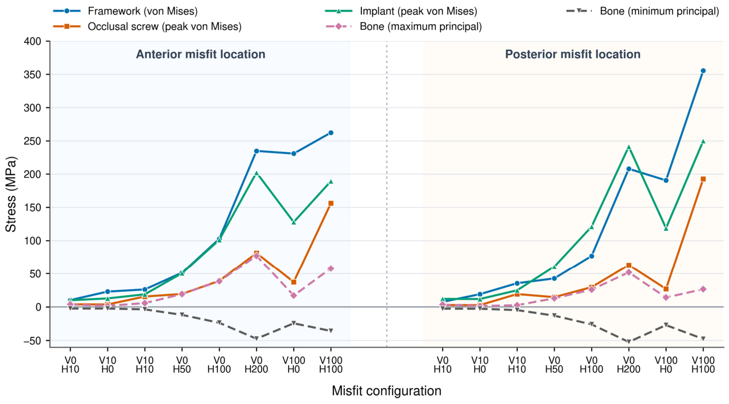
Framework stress increased progressively with isolated horizontal misfit magnitude at both locations. At the shared numerical values of 10 and 100 µm, vertical misfit produced higher framework stress than horizontal misfit when compared at the same location under otherwise identical model conditions. At 100 µm, the corresponding values were 231 versus 103 MPa for anterior misfit and 191 versus 77 MPa for posterior misfit. Combined misfit produced higher stresses than either isolated component at both magnitudes. Anterior misfit generated higher framework stresses in the isolated conditions, whereas posterior misfit generated higher stresses in the combined conditions. The overall maximum occurred in V100 H100 P (356 MPa) (Figure 2).
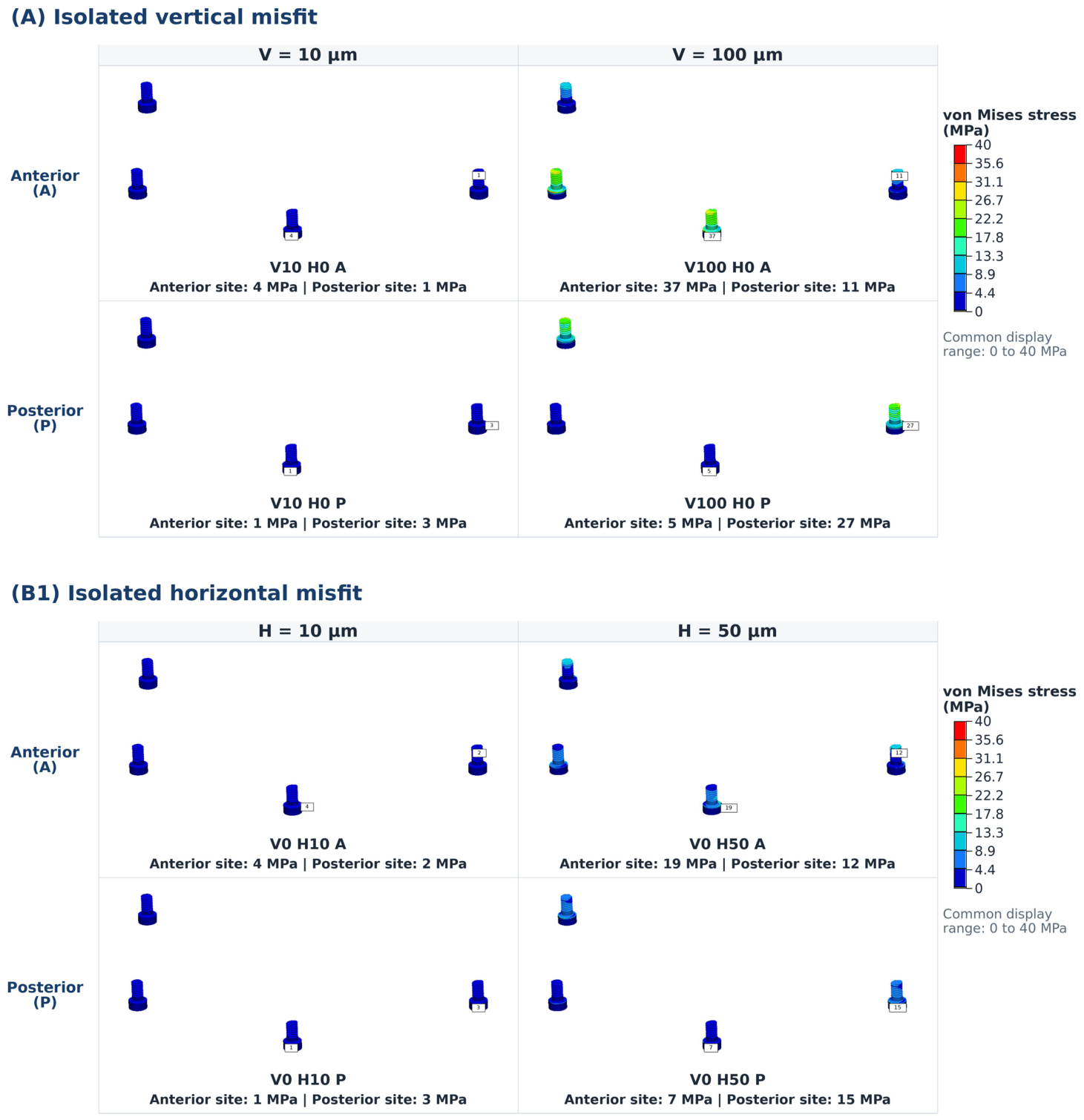
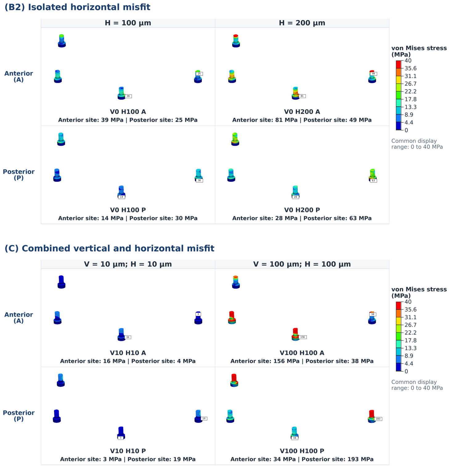
Occlusal-screw stress was consistently higher at the screw corresponding to the misfit location and increased with isolated horizontal misfit magnitude. Combined misfit produced the greatest values, with the overall maximum at the posterior screw in V100 H100 P (193 MPa) (Figure 3).
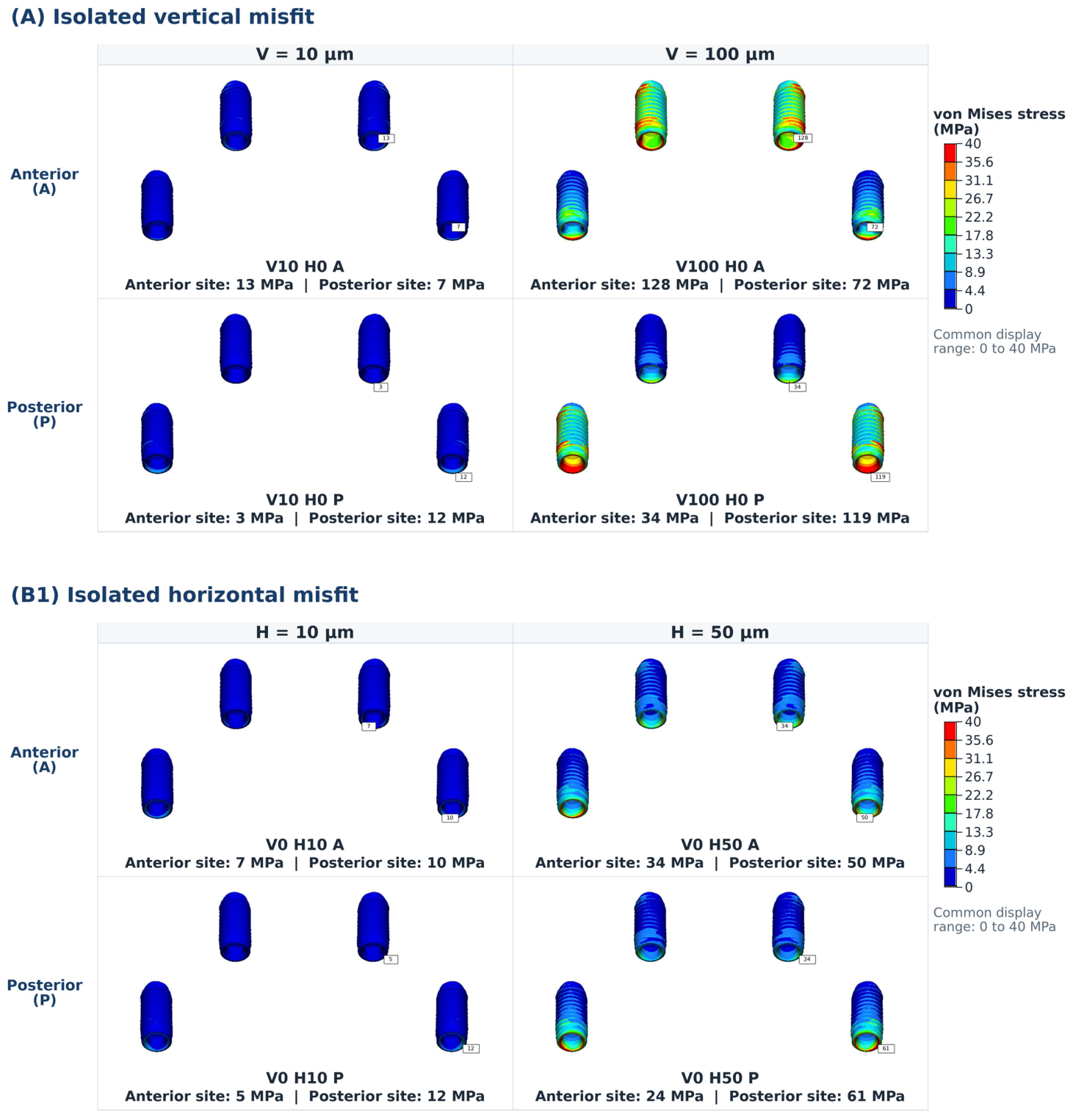
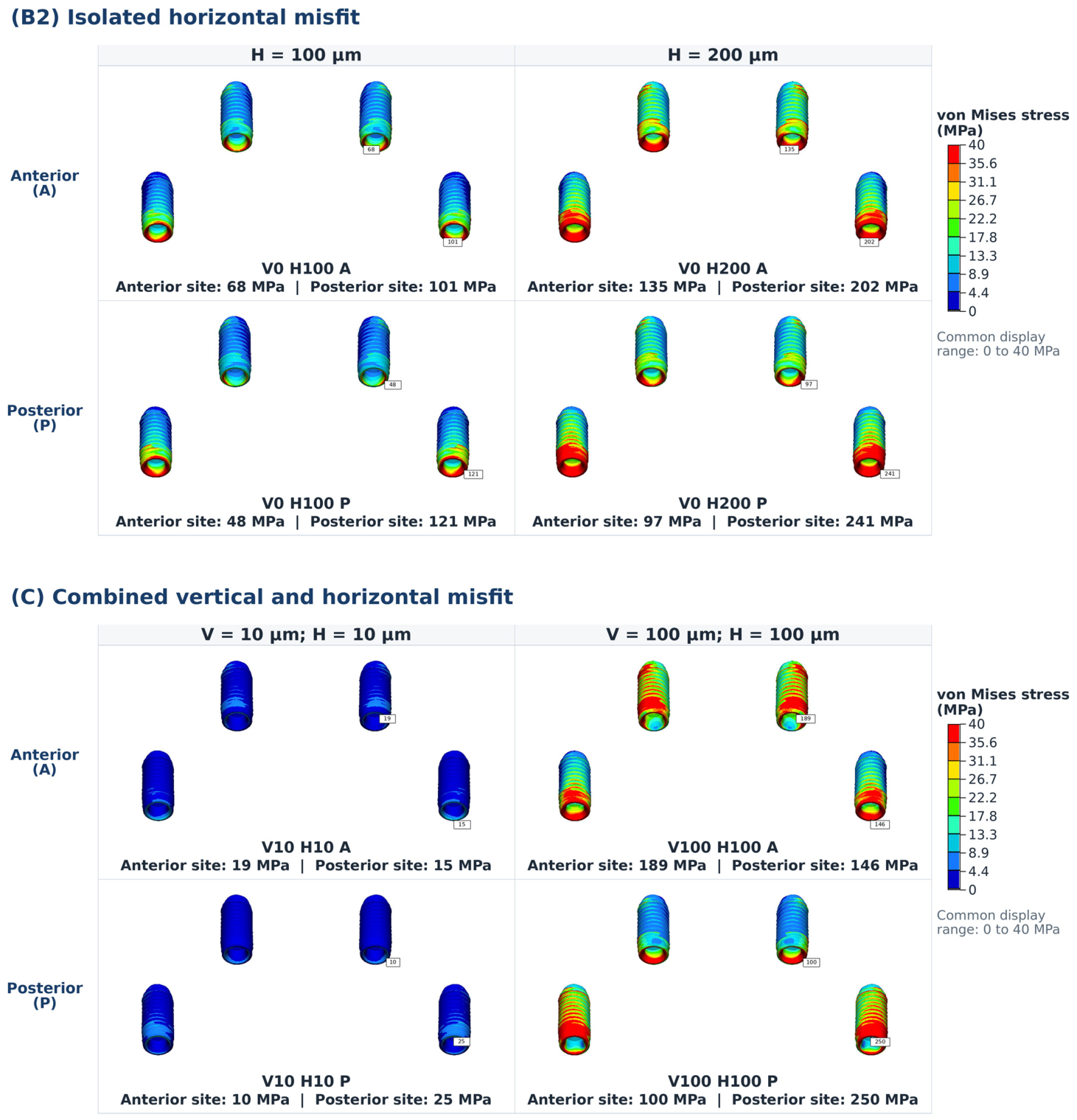
Implant stress increased progressively with isolated horizontal misfit magnitude at both implant sites. The greatest values occurred in the high-magnitude combined and isolated-horizontal conditions, with the overall maximum in V100 H100 P (250 MPa), followed by V0 H200 P (241 MPa) (Figure 4).
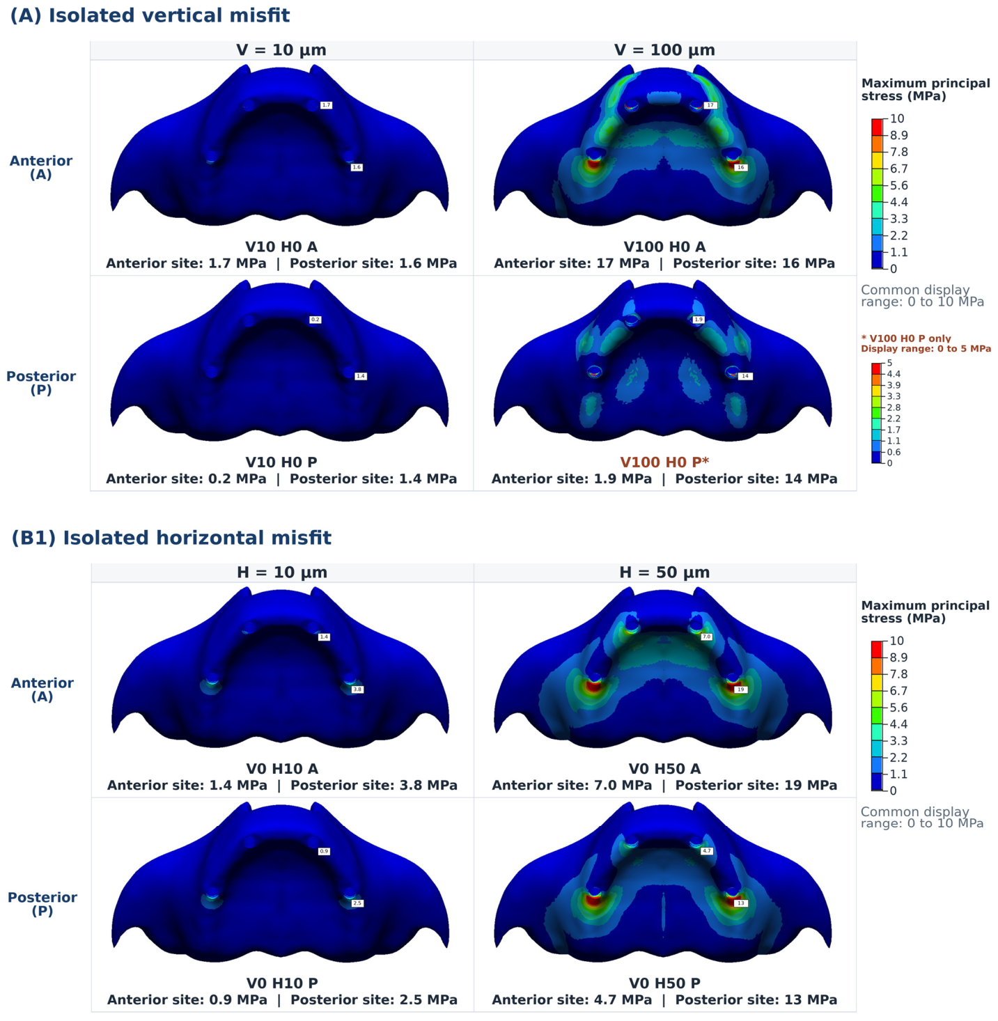
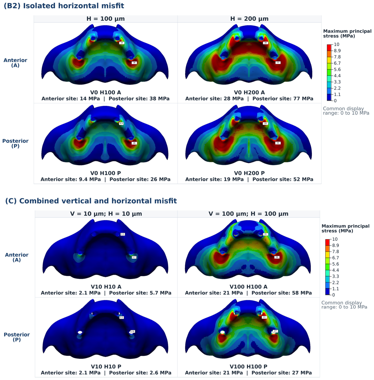
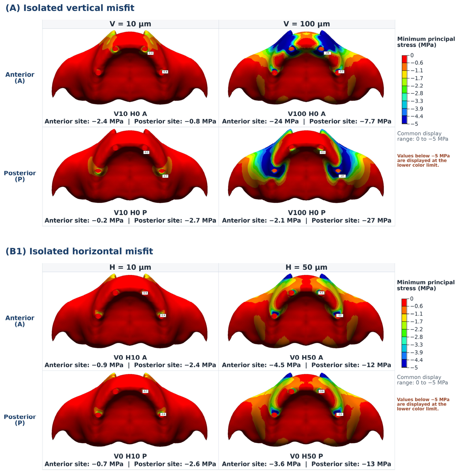
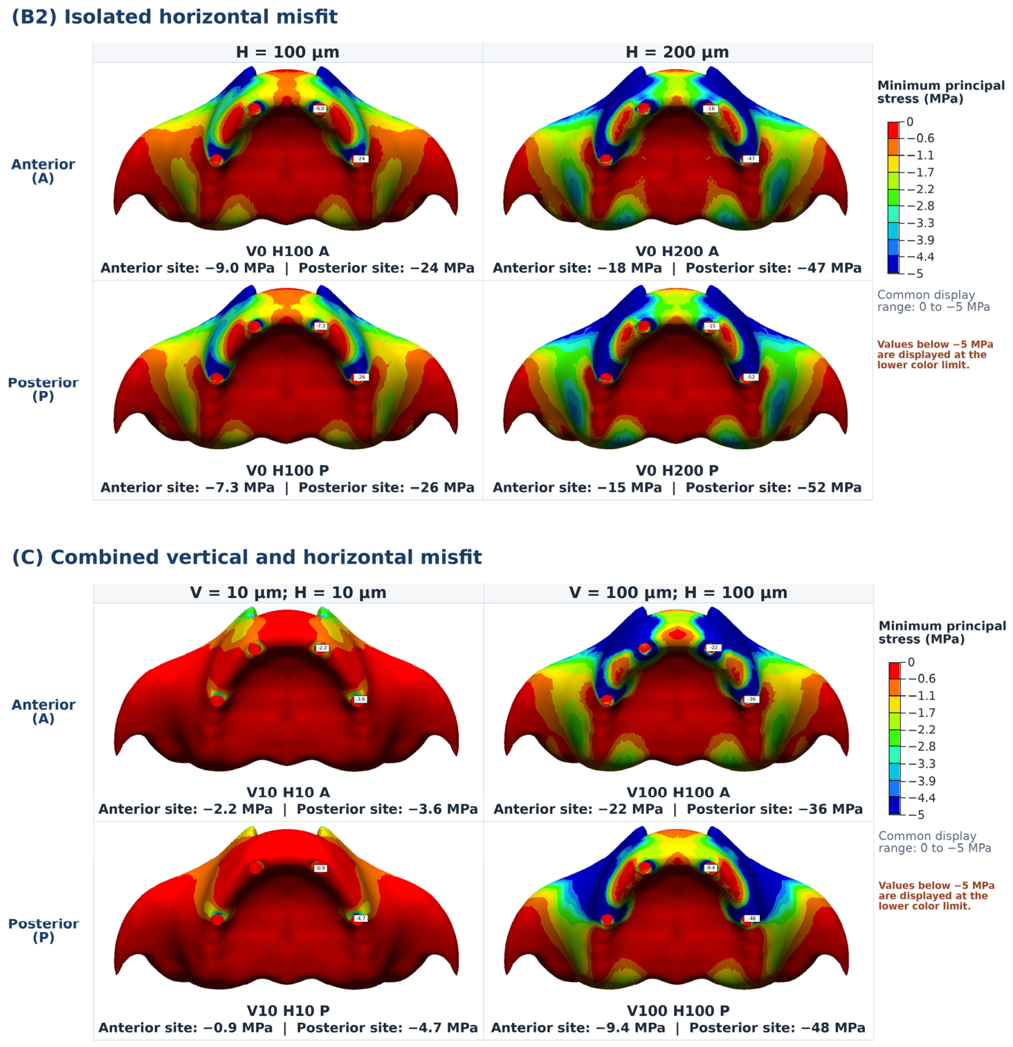
In the peri-implant bone, both maximum principal stress and the magnitude of minimum principal stress increased with isolated horizontal misfit magnitude. Unlike the framework, screws, and implants, the bone-stress extrema occurred in the V0 H200 conditions: the highest tensile stress was 77 MPa at the posterior bone site in V0 H200 A, and the greatest compressive stress was −52 MPa at the posterior site in V0 H200 P. Thus, the greatest bone response did not always coincide with the misfit location (Figure 5 and Figure 6). Peak stress trends across all scenarios are summarized in Figure 7.

4. Discussion

This study evaluated how the types, magnitudes, and locations of misfits affect stress transfer in a full-arch screw-retained implant framework. Because stress patterns differed among scenarios, the null hypothesis was rejected. V0 H10, V10 H0, and V10 H10 represented reduced-magnitude misfits, rather than passive controls. V0 H0 was omitted because, without a geometric discrepancy, closure displacement, screw preload, or external loading, a passively fitting assembly would generate no misfit-induced stress [7].
At matched locations, vertical misfits produced greater framework stress than horizontal misfits at both 10 and 100 µm; for example, at the anterior site, the values were 231 and 103 MPa, respectively, under a 100 µm misfit. Holding magnitude and location constant allowed for isolation of the effects of discrepancy orientation and seating direction, rather than assuming mechanical equivalence. Vertical and horizontal closures likely influence different combinations of bending, axial deformation, and shear in the connected framework, although it should be noted that these modes were not quantified separately. Thus, although equal-sized discrepancies in different directions should not be assumed to be biomechanically equivalent, the results do not define direction-specific clinical tolerances.
No universal MPa threshold exists for framework stress in full-arch prostheses; the von Mises stress should be considered relative to material strength and fatigue resistance. Previous FEA-based research has shown that increasing horizontal misfit raises stress in the bar, screw, implant, and cortical bone [19], while experimental and numerical studies have reported associations between misfit and veneer fracture or chipping [20,26]. In this study, the peak misfit-related stress was greater in the framework than in the screws, indicating greater framework demand under the modeled conditions.
The zirconia superstructure was stiffer than the titanium components in the model (200 vs. 110 GPa). Through FREEZE contact, it formed a bonded composite with the framework, reducing local compliance and potentially increasing reaction forces and the transmission of seating deformation across the arch. Its independent contribution, however, cannot be determined without material and interface sensitivity analyses.
Peak cortical bone tensile and compressive stresses (approximately 77 and 52 MPa, respectively) remained below commonly cited strength ranges [27,28], although compressive stress increased markedly under the 200 µm horizontal and 100–100 µm combined misfit configurations. As bone adaptation is better characterized using strain-based mechanobiology than principal stress alone, these values should be considered to indicate relative demand and localization, and not long-term adaptation or clinical risk [29,30]. Volumetric framework misfit has been quantified in vitro [31], and studies [32,33] have examined peri-implant responses under static loading and ill-fitting prostheses; however, the long-term association with bone-related complications remains uncertain [34]. Our findings complement those of Abdelrehim et al. [5]; in particular, while their reported ranges indicate the absence of observed complications, the present idealized displacement-controlled FEA compared relative stress responses and did not establish failure thresholds.
Previous studies have generally evaluated vertical and horizontal misfit separately [19,35,36,37]. However, combined closure requires the correction of a vertical gap and horizontal offset within the same constrained assembly, combining vertical and lateral bending with shear. This multiaxial response likely contributes to the higher von Mises stresses. Although combined conditions also had greater resultant displacement than the corresponding isolated conditions, the results do not establish nonlinear synergy. Nevertheless, V100 H100 produced greater framework stress than V0 H200 despite its smaller resultant displacement, showing that the direction and constraint pattern cannot be neglected. Experimental evidence indicates that there is a direct relationship between vertical misfit and peri-implant strain during framework fitting [38]. However, the influence of screw tightening on the effect of a combined misfit remains unknown, as sequential tightening and nonlinear contact modeling were not performed. Together with the veneer cracking and torque loss effects reported under misfit [26,39,40], this study’s findings support the need to minimize combined discrepancies rather than judging acceptability from the visible gap magnitude alone.
Horizontal misfit has been associated with increased screw and implant stress [19,37]. In this context, closure transverse to the screw–abutment axis likely generates an eccentric reaction and local bending and shear at the discrepant connection. Under the bonded-interface idealization in this study, this reaction followed the screw–framework–abutment load path and led to stress concentration in the corresponding screw. Tightening torque and implant–abutment contact can also influence screw stress and microgap formation [41]. As preload, frictional thread contact, sequential tightening, and contact or micromobility at the intentionally discrepant interface were not modeled in this study, the reported screw values represent displacement-induced demand rather than total post-tightening stress; clinical tightening could alter interface contact and lead to stress redistribution. As the lever arm increases bending moments, posterior implants often experience greater demand under distal cantilever loading [42,43]. Such a mechanism was not directly reproduced in this study, because no occlusal load was applied. Therefore, posterior dominance was not uniform; in particular, isolated misfits produced greater framework stress when applied anteriorly, whereas the high-magnitude combined condition produced the greatest framework, screw, and implant stresses in the posterior configuration. Screw stress was localized at the discrepant connection, but peak tensile bone stress occurred posteriorly with an anterior 200 µm horizontal misfit. Thus, localization reflects the closure pathway, seated connections, framework continuity, component stiffness, and constraints—not cantilever alone—and the misfit site does not necessarily coincide with the maximum-stress site.
As the geometry, mesh, materials, boundary conditions, and interfaces were held constant, the most defensible findings of this study are the internally consistent comparative trends. In particular, stress rose across the isolated horizontal misfit series; combined misfits produced the highest framework and screw stresses and the maximum implant stress among the tested scenarios; and high stresses were not consistently confined to posterior sites. However, the absolute stresses, vertical–horizontal differences, anterior–posterior rankings, and clinical implications remain sensitive to displacement-controlled seating; omission of preload, sequential tightening, and functional or cyclic loading; and idealized contact, material, and boundary assumptions. Displacement-controlled misfit modeling has been performed previously [19], and misfit-induced peri-implant bone stress has been evaluated in multi-implant FEA-based research [44]. The uniform 2 mm cortical shell was not intended to represent patient- or site-specific maxillary anatomy, and may have affected the magnitude and localization of the bone stress results [22,24]. Sinus pneumatization may preclude parallel posterior placement in atrophic maxillae, and distal tilt was not tested. Finally, the vertical series was limited to 10 and 100 µm and, thus, a full dose–response relationship cannot be defined. Nonlinear contact and preload analyses, sensitivity testing, and experimental or clinical validation will be required before the values reported here can be translated into thresholds or indicators of complication risk.

5. Conclusions

Within the limitations of this finite element model, combined misfit produced the highest framework and occlusal-screw stresses among the tested scenarios, whereas implant and peri-implant bone responses varied with misfit magnitude and location. These findings describe comparative biomechanical trends and stress localization patterns rather than clinical acceptability thresholds. Clinically, combined misfits warrant particular attention during framework fit assessment before definitive seating.

Author Contributions

Conceptualization, H.A.K. and M.B.G.; methodology, H.A.K. and M.B.G.; investigation, H.A.K.; data curation, H.A.K.; writing—original draft preparation, H.A.K.; writing—review and editing, H.A.K. and M.B.G.; visualization, H.A.K.; supervision, M.B.G.; project administration, H.A.K.; funding acquisition, H.A.K. All authors have read and agreed to the published version of the manuscript.

Funding

This research was funded by the Başkent University Research Fund under Project No. D-DA25/13.

Institutional Review Board Statement

Not applicable.

Informed Consent Statement

Not applicable.

Data Availability Statement

The original contributions presented in the study are included in the article, further inquiries can be directed to the corresponding author.

Conflicts of Interest

The authors declare no conflicts of interest.

References

  1. Papaspyridakos, P.; Barizan Bordin, T.; Kim, Y.J.; DeFuria, C.; Pagni, S.E.; Chochlidakis, K.; Rolim Teixeira, E.; Weber, H.P. Implant survival rates and biologic complications with implant-supported fixed complete dental prostheses: A retrospective study with up to 12-year follow-up. Clin. Oral Implant. Res. 2018, 29, 881–893. [Google Scholar] [CrossRef] [Scilit] [PubMed]
  2. Romeo, E.; Storelli, S. Systematic review of the survival rate and the biological, technical, and aesthetic complications of fixed dental prostheses with cantilevers on implants reported in longitudinal studies with a mean of 5 years follow-up. Clin. Oral Implant. Res. 2012, 23, 39–49. [Google Scholar] [CrossRef] [Scilit] [PubMed]
  3. Sadowsky, S.J. The implant-supported prosthesis for the edentulous arch: Design considerations. J. Prosthet. Dent. 1997, 78, 28–33. [Google Scholar] [CrossRef] [Scilit] [PubMed]
  4. Katsoulis, J.; Takeichi, T.; Sol Gaviria, A.; Peter, L.; Katsoulis, K. Misfit of implant prostheses and its impact on clinical outcomes. Definition, assessment and a systematic review of the literature. Eur. J. Oral Implantol. 2017, 10, 121–138. [Google Scholar] [PubMed]
  5. Abdelrehim, A.; Etajuri, E.A.; Sulaiman, E.; Sofian, H.; Salleh, N.M. Magnitude of misfit threshold in implant-supported restorations: A systematic review. J. Prosthet. Dent. 2024, 132, 528–535. [Google Scholar] [CrossRef] [Scilit] [PubMed]
  6. Kan, J.Y.; Rungcharassaeng, K.; Bohsali, K.; Goodacre, C.J.; Lang, B.R. Clinical methods for evaluating implant framework fit. J. Prosthet. Dent. 1999, 81, 7–13. [Google Scholar] [CrossRef] [Scilit] [PubMed]
  7. Sahin, S.; Çehreli, M.C. The significance of passive framework fit in implant prosthodontics: Current status. Implant Dent. 2001, 10, 85–92. [Google Scholar] [CrossRef] [Scilit] [PubMed]
  8. Jemt, T. A retro-prospective effectiveness study on 3448 implant operations at one referral clinic: A multifactorial analysis. Part II: Clinical factors associated to peri-implantitis surgery and late implant failures. Clin. Implant Dent. Relat. Res. 2017, 19, 972–979. [Google Scholar] [CrossRef] [Scilit] [PubMed]
  9. Buzayan, M.M.; Yunus, N.B. Passive fit in screw retained multi-unit implant prosthesis understanding and achieving: A review of the literature. J. Indian Prosthodont. Soc. 2014, 14, 16–23. [Google Scholar] [CrossRef] [Scilit] [PubMed]
  10. Kano, S.C.; Binon, P.P.; Curtis, D.A. A classification system to measure the implant-abutment microgap. Int. J. Oral Maxillofac. Implant. 2007, 22, 879–885. [Google Scholar]
  11. Abduo, J.; Bennani, V.; Waddell, N.; Lyons, K.; Swain, M. Assessing the fit of implant fixed prostheses: A critical review. Int. J. Oral Maxillofac. Implant. 2010, 25, 506–515. [Google Scholar]
  12. Pan, Y.; Tsoi, J.K.H.; Lam, W.Y.H.; Pow, E.H.N. Implant framework misfit: A systematic review on assessment methods and clinical complications. Clin. Implant Dent. Relat. Res. 2021, 23, 244–258. [Google Scholar] [CrossRef] [Scilit] [PubMed]
  13. Jemt, T. Failures and complications in 391 consecutively inserted fixed prostheses supported by Brånemark implants in edentulous jaws: A study of treatment from the time of prosthesis placement to the first annual checkup. Int. J. Oral Maxillofac. Implant. 1991, 6, 270–276. [Google Scholar]
  14. Al-Fadda, S.A.; Zarb, G.A.; Finer, Y. A comparison of the accuracy of fit of 2 methods for fabricating implant-prosthodontic frameworks. Int. J. Prosthodont. 2007, 20, 125–131. [Google Scholar] [PubMed]
  15. Menini, M.; Setti, P.; Pera, F.; Pera, P.; Pesce, P. Accuracy of multi-unit implant impression: Traditional techniques versus a digital procedure. Clin. Oral Investig. 2018, 22, 1253–1262. [Google Scholar] [CrossRef] [Scilit] [PubMed]
  16. Rutkūnas, V.; Kuleš, D.; Mischitz, I.; Huber, S.; Revilla-León, M.; Larsson, C.; Janda, M. Misfit simulation on implant-supported prostheses with different combinations of engaging and nonengaging titanium bases: Part 3: A radiographic evaluation. J. Prosthet. Dent. 2025, 133, 222–228. [Google Scholar] [CrossRef] [Scilit] [PubMed]
  17. Bhering, C.L.B.; Mesquita, M.F.; Kemmoku, D.T.; Noritomi, P.Y.; Consani, R.L.X.; Barão, V.A.R. Comparison between All-on-Four and All-on-Six treatment concepts and framework material on stress distribution in atrophic maxilla: A prototyping-guided 3D-FEA study. Mater. Sci. Eng. C Mater. Biol. Appl. 2016, 69, 715–725. [Google Scholar] [CrossRef] [Scilit] [PubMed]
  18. Dayan, S.C.; Geckili, O. The influence of framework material on stress distribution in maxillary complete-arch fixed prostheses supported by four dental implants: A three-dimensional finite element analysis. Comput. Methods Biomech. Biomed. Engin. 2021, 24, 1606–1617. [Google Scholar] [CrossRef] [Scilit] [PubMed]
  19. Spazzin, A.O.; dos Santos, M.B.F.; Correr-Sobrinho, L.; Consani, R.L.X.; Mesquita, M.F. Effects of horizontal misfit and bar framework material on the stress distribution of an overdenture-retaining bar system: A 3D finite element analysis. J. Prosthodont. 2011, 20, 517–522. [Google Scholar] [CrossRef] [Scilit] [PubMed]
  20. Janda, M.; Larsson, C.; Mattheos, N. Influence of misfit on the occurrence of porcelain veneer fractures in implant-supported metal-ceramic fixed dental prostheses. Part 2: A three-dimensional finite element analysis. Int. J. Prosthodont. 2021, 34, 458–462. [Google Scholar] [PubMed]
  21. Fontanella, C.G.; Carniel, E.L.; Parpaiola, A.; Toia, M.; Natali, A.N. Interaction phenomena between dental implants and bone tissue in case of misfit: A pilot study. Appl. Sci. 2023, 13, 6004. [Google Scholar] [CrossRef] [Scilit]
  22. Wang, S.-H.; Shen, Y.-W.; Fuh, L.-J.; Peng, S.-L.; Tsai, M.-T.; Huang, H.-L.; Hsu, J.-T. Relationship between cortical bone thickness and cancellous bone density at dental implant sites in the jawbone. Diagnostics 2020, 10, 710. [Google Scholar] [CrossRef] [Scilit] [PubMed]
  23. Kelkar, K.C.; Bhat, V.; Hegde, C. Finite element analysis of the effect of framework materials at the bone–implant interface in the All-on-Four implant system. Dent. Res. J. 2021, 18, 1. [Google Scholar] [CrossRef] [Scilit]
  24. Katranji, A.; Misch, K.; Wang, H.-L. Cortical bone thickness in dentate and edentulous human cadavers. J. Periodontol. 2007, 78, 874–878. [Google Scholar] [CrossRef] [Scilit] [PubMed]
  25. Cinel, S.; Celik, E.; Sagirkaya, E.; Sahin, O. Experimental evaluation of stress distribution with narrow diameter implants: A finite element analysis. J. Prosthet. Dent. 2018, 119, 417–425. [Google Scholar] [CrossRef] [Scilit] [PubMed]
  26. Löfgren, N.; Larsson, C.; Mattheos, N.; Janda, M. Influence of misfit on the occurrence of veneering porcelain fractures (chipping) in implant-supported metal-ceramic fixed dental prostheses: An in vitro pilot trial. Clin. Oral Implant. Res. 2017, 28, 1381–1387. [Google Scholar] [CrossRef] [Scilit] [PubMed]
  27. Choi, S.-M.; Choi, H.; Lee, D.-H.; Hong, M.-H. Comparative finite element analysis of mandibular posterior single zirconia and titanium implants: A 3-dimensional finite element analysis. J. Adv. Prosthodont. 2021, 13, 396–407. [Google Scholar] [CrossRef] [Scilit] [PubMed]
  28. Zapata, J.M.; Leal, E.; Hunter, R.; de Souza, R.F.; Borie, E. Biomechanical behavior of narrow dental implants made with aluminum- and vanadium-free alloys: A finite element analysis. Materials 2022, 15, 8903. [Google Scholar] [CrossRef] [Scilit] [PubMed]
  29. Frost, H.M. Bone’s mechanostat: A 2003 update. Anat. Rec. A Discov. Mol. Cell. Evol. Biol. 2003, 275A, 1081–1101. [Google Scholar] [CrossRef] [Scilit] [PubMed]
  30. Huiskes, R.; Weinans, H.; Grootenboer, H.J.; Dalstra, M.; Fudala, B.; Slooff, T.J. Adaptive bone-remodeling theory applied to prosthetic-design analysis. J. Biomech. 1987, 20, 1135–1150. [Google Scholar] [CrossRef] [Scilit] [PubMed]
  31. Almasri, R.; Drago, C.J.; Siegel, S.C.; Hardigan, P.C. Volumetric misfit in CAD/CAM and cast implant frameworks: A university laboratory study. J. Prosthodont. 2011, 20, 267–274. [Google Scholar] [CrossRef] [Scilit] [PubMed]
  32. Gotfredsen, K.; Berglundh, T.; Lindhe, J. Bone reactions adjacent to titanium implants subjected to static load of different duration: A study in the dog (III). Clin. Oral Implant. Res. 2001, 12, 552–558. [Google Scholar] [CrossRef] [Scilit] [PubMed]
  33. Duyck, J.; Vrielinck, L.; Lambrichts, I.; Abe, Y.; Schepers, S.; Politis, C.; Naert, I. Biologic response of immediately versus delayed loaded implants supporting ill-fitting prostheses: An animal study. Clin. Implant Dent. Relat. Res. 2005, 7, 150–158. [Google Scholar] [CrossRef] [Scilit] [PubMed]
  34. Jokstad, A.; Shokati, B. New 3D technologies applied to assess the long-term clinical effects of misfit of the full-jaw fixed prosthesis on dental implants. Clin. Oral Implant. Res. 2015, 26, 1129–1134. [Google Scholar] [CrossRef] [Scilit] [PubMed]
  35. de Torres, E.M.; Barbosa, G.A.S.; Bernardes, S.R.; de Mattos, M.G.C.; Ribeiro, R.F. Correlation between vertical misfits and stresses transmitted to implants from metal frameworks. J. Biomech. 2011, 44, 1735–1739. [Google Scholar] [CrossRef] [Scilit] [PubMed]
  36. Barbosa, G.A.S.; Das Neves, F.D.; de Mattos, M.G.C.; Rodrigues, R.C.S.; Ribeiro, R.F. Implant/abutment vertical misfit of one-piece cast frameworks made with different materials. Braz. Dent. J. 2010, 21, 515–519. [Google Scholar] [CrossRef] [Scilit] [PubMed]
  37. Caldas, R.A.; Pfeifer, C.S.C.; Bacchi, A.; dos Santos, M.B.F.; Reginato, V.F.; Consani, R.L.X. Implant inclination and horizontal misfit in metallic bar framework of overdentures: Analysis by 3D-FEA method. Braz. Dent. J. 2018, 29, 166–172. [Google Scholar] [CrossRef] [Scilit] [PubMed]
  38. Abduo, J.; Swain, M. Influence of vertical misfit of titanium and zirconia frameworks on peri-implant strain. Int. J. Oral Maxillofac. Implant. 2012, 27, 529–536. [Google Scholar]
  39. Al-Turki, L.E.; Chai, J.; Lautenschlager, E.P.; Hutten, M.C. Changes in prosthetic screw stability because of misfit of implant-supported prostheses. Int. J. Prosthodont. 2002, 15, 38–42. [Google Scholar] [PubMed]
  40. Stimmelmayr, M.; Groesser, J.; Beuer, F.; Erdelt, K.; Krennmair, G.; Sachs, C.; Edelhoff, D.; Güth, J.F. Accuracy and mechanical performance of passivated and conventional fabricated 3-unit fixed dental prosthesis on multi-unit abutments. J. Prosthodont. Res. 2017, 61, 403–411. [Google Scholar] [CrossRef] [Scilit] [PubMed]
  41. Tonin, B.S.H.; He, Y.; Ye, N.; Chew, H.P.; Fok, A. Effects of tightening torque on screw stress and formation of implant-abutment microgaps: A finite element analysis. J. Prosthet. Dent. 2022, 127, 882–889. [Google Scholar] [CrossRef] [Scilit] [PubMed]
  42. Bevilacqua, M.; Tealdo, T.; Menini, M.; Pera, F.; Mossolov, A.; Drago, C.; Pera, P. The influence of cantilever length and implant inclination on stress distribution in maxillary implant-supported fixed dentures. J. Prosthet. Dent. 2011, 105, 5–13. [Google Scholar] [CrossRef] [Scilit] [PubMed]
  43. Sertgöz, A.; Güvener, S. Finite element analysis of the effect of cantilever and implant length on stress distribution in an implant-supported fixed prosthesis. J. Prosthet. Dent. 1996, 76, 165–169. [Google Scholar] [CrossRef] [Scilit] [PubMed]
  44. Natali, A.N.; Pavan, P.G.; Ruggero, A.L. Evaluation of stress induced in peri-implant bone tissue by misfit in multi-implant prosthesis. Dent. Mater. 2006, 22, 388–395. [Google Scholar] [CrossRef] [Scilit] [PubMed]
Figure 1. Three-dimensional finite element model: (A) assembled maxillary model; (B) exploded view of the implants, multi-unit abutments, titanium framework, occlusal screws, and zirconia superstructure.
Jfb 17 00478 g001
Figure 2. Von Mises stress distributions in the titanium framework for (A) isolated vertical, (B1,B2) isolated horizontal, and (C) combined misfit scenarios. Stress values are expressed in MPa. Boxed numbers indicate the site-specific stress values.
Jfb 17 00478 g002aJfb 17 00478 g002b
Figure 3. Von Mises stress distributions in the occlusal screws for (A) isolated vertical, (B1,B2) isolated horizontal, and (C) combined misfit scenarios. Stress values are expressed in MPa. Boxed numbers indicate the site-specific stress values.
Jfb 17 00478 g003aJfb 17 00478 g003b
Figure 4. Von Mises stress distributions in the implants for (A) isolated vertical, (B1,B2) isolated horizontal, and (C) combined misfit scenarios. Stress values are expressed in MPa. Boxed numbers indicate the site-specific stress values.
Jfb 17 00478 g004aJfb 17 00478 g004b
Figure 5. Maximum principal stress distributions in the peri-implant bone for (A) isolated vertical, (B1,B2) isolated horizontal, and (C) combined misfit scenarios. Stress values are expressed in MPa. Boxed numbers indicate the site-specific stress values.
Jfb 17 00478 g005aJfb 17 00478 g005b
Figure 6. Minimum principal stress distributions in the peri-implant bone for (A) isolated vertical, (B1,B2) isolated horizontal, and (C) combined misfit scenarios. Stress values are expressed in MPa. Boxed numbers indicate the site-specific stress values.
Jfb 17 00478 g006aJfb 17 00478 g006b
Figure 7. Peak stresses across anterior and posterior misfit scenarios, showing von Mises stresses in the framework, occlusal screws, and implants and principal stresses in peri-implant bone (MPa).
Jfb 17 00478 g007
Table 1. Misfit scenarios and configurations.
GroupScenario Code and Misfit
Location
Vertical Misfit, V
(µm)
Horizontal Misfit, H
(µm)
Misfit Configuration
V0 H10V0 H10 A—anterior
V0 H10 P—posterior
010Isolated horizontal
V10 H0V10 H0 A—anterior
V10 H0 P—posterior
100Isolated vertical
V10 H10V10 H10 A—anterior
V10 H10 P—posterior
1010Combined vertical and horizontal
V0 H50V0 H50 A—anterior
V0 H50 P—posterior
050Isolated horizontal
V0 H100V0 H100 A—anterior
V0 H100 P—posterior
0100Isolated horizontal
V0 H200V0 H200 A—anterior
V0 H200 P—posterior
0200Isolated horizontal
V100 H0V100 H0 A—anterior
V100 H0 P—posterior
1000Isolated vertical
V100 H100V100 H100 A—anterior
V100 H100 P—posterior
100100Combined vertical and horizontal
Table 2. Nominal element sizes and mesh characteristics of the model components.
Component/ScenarioSurface-Element Size Range (mm)Number of NodesNumber of Tetrahedral Elements
Shared model components
Cortical bone0.10–0.2537,506138,064
Trabecular bone0.10–0.2567,680274,723
Implant component set0.1036,667146,151
Multi-unit abutment component set0.1016,86266,574
Occlusal screw component set0.10362612,761
Zirconia prosthesis0.1052,952218,828
Scenario-specific titanium framework meshes
Titanium framework—V0 H10 A0.1067,377280,373
Titanium framework—V0 H10 P0.1066,773277,907
Titanium framework—V10 H0 A0.1066,492276,336
Titanium framework—V10 H0 P0.1066,972278,752
Titanium framework—V10 H10 A0.1067,369280,418
Titanium framework—V10 H10 P0.1066,766277,896
Titanium framework—V0 H50 A0.1066,695277,059
Titanium framework—V0 H50 P0.1066,893278,141
Titanium framework—V0 H100 A0.1065,842272,917
Titanium framework—V0 H100 P0.1067,043278,434
Titanium framework—V0 H200 A0.1066,232274,452
Titanium framework—V0 H200 P0.1066,870277,191
Titanium framework—V100 H0 A0.1066,417276,741
Titanium framework—V100 H0 P0.1066,905278,654
Titanium framework—V100 H100 A0.1065,942273,821
Titanium framework—V100 H100 P0.1066,559277,287
Note: Counts for the implant, multi-unit abutment, and occlusal screw represent one symmetric component set; two identical sets were included in the four-implant model. Framework counts varied slightly because each discrepancy geometry was meshed separately.
Disclaimer/Publisher’s Note: The statements, opinions and data contained in all publications are solely those of the individual author(s) and contributor(s) and not of MDPI and/or the editor(s). MDPI and/or the editor(s) disclaim responsibility for any injury to people or property resulting from any ideas, methods, instructions or products referred to in the content.