

Three-Axis Plate for Open Rigid Internal Fixation of Base Fracture of Mandibular Condyle


Abstract

1. Introduction
2. Materials and Methods
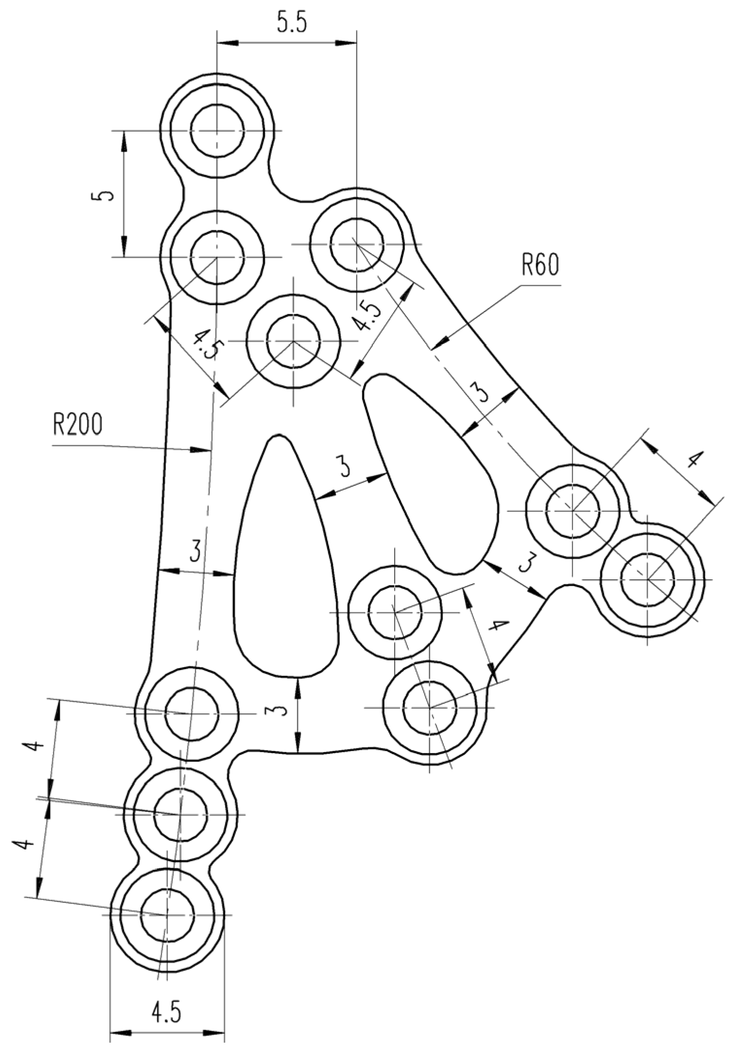
2.1. Design
2.2. Assessment
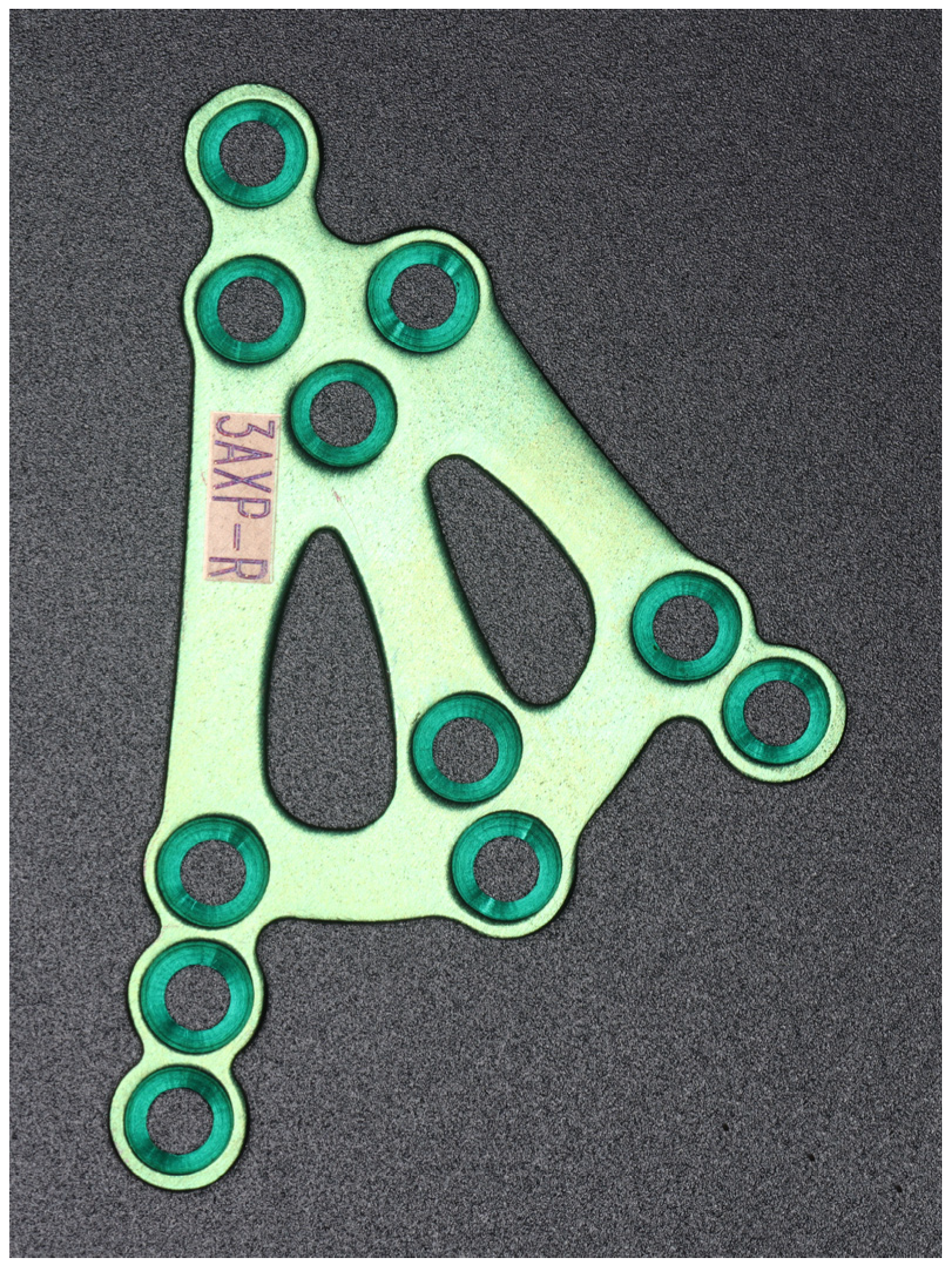
2.3. Implant Specifications
2.4. Manufacturing
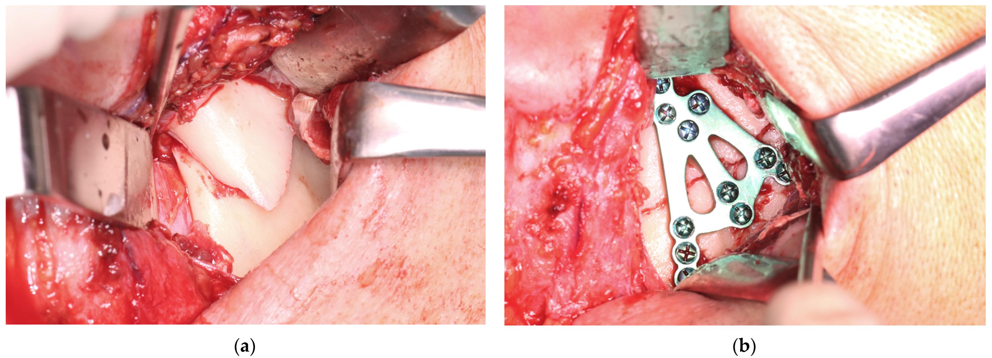
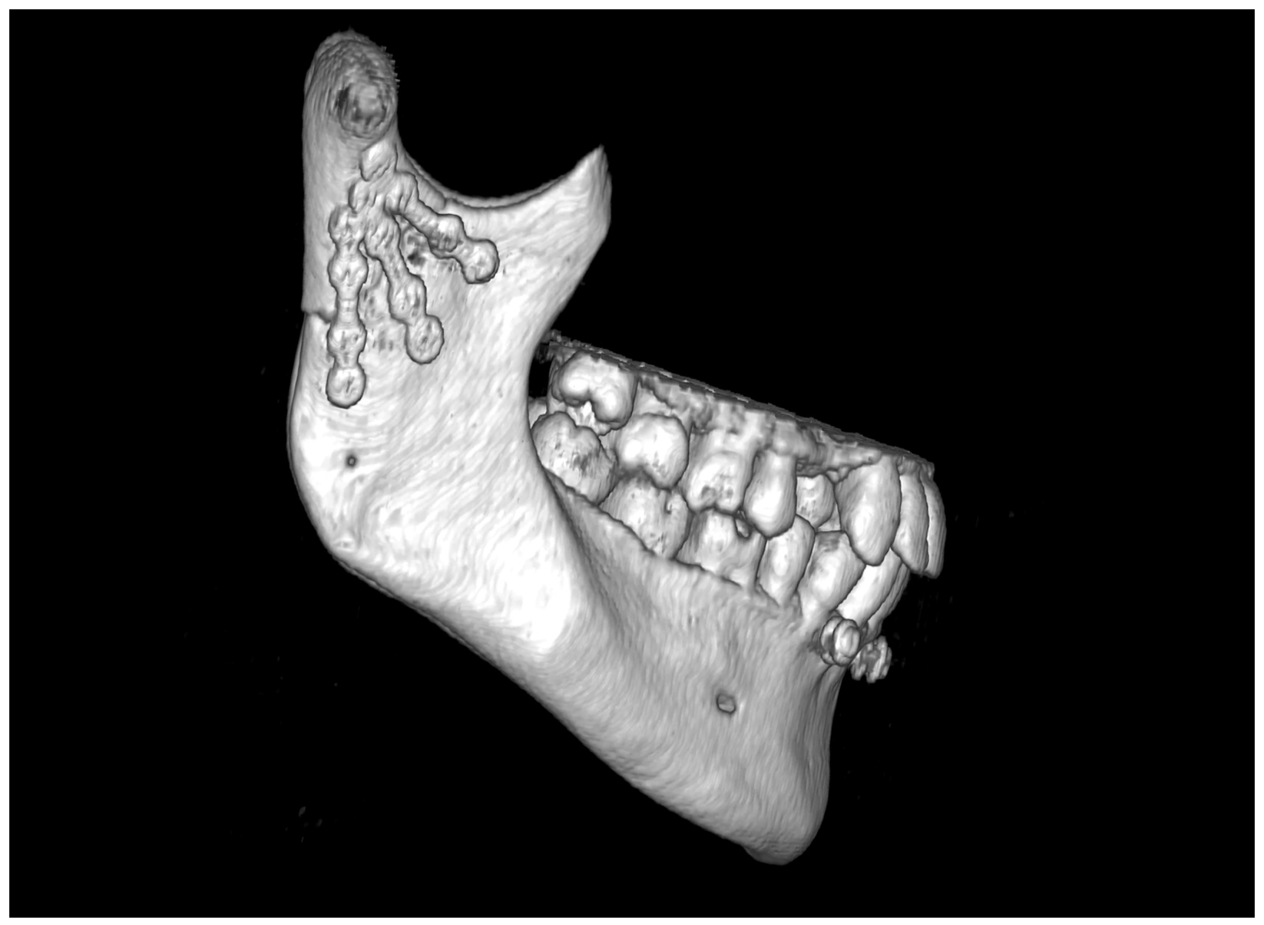
3. Results
4. Discussion
5. Conclusions
Supplementary Materials
Funding
Institutional Review Board Statement
Informed Consent Statement
Data Availability Statement
Conflicts of Interest
References
- Hansmann, W. Eine neue Methode der Fixierung der Fragmente bei complicierten Fracturen. Verh. Dtsch. Ges. Chir. 1886, 15, 134. [Google Scholar]
- Bigelow, H.M. Vitallium bone screws and appliances for treatment of fracture of mandible. J. Oral. Surg. 1943, 1, 131. [Google Scholar]
- Smith, A.E.; Robinson, M. Stainless steel bone onlay splints for the immobilization of displaced condylar fractures; a new technic: Report of three cases, one of ten years’ duration. J. Oral. Surg. 1957, 15, 164–172. [Google Scholar]
- Robinson, M. Immobilization of subcondylar fractures after open reduction. J. South. Calif. Dent. Assoc. 1958, 26, 330. [Google Scholar]
- Robinson, M.; Yoon, C. New onlay-inlay metal splint for immobilization of mandibular subcondylar fracture. Report of twenty-six cases. Am. J. Surg. 1960, 100, 845–849. [Google Scholar] [CrossRef]
- Robinson, M.; Yoon, C. The ‘L’ splint for the fractured mandible: A new principle of plating. J. Oral. Surg. Anesth. Hosp. Dent. Serv. 1963, 21, 395–399. [Google Scholar]
- Leonhardt, H.; Franke, A.; McLeod, N.M.H.; Lauer, G.; Nowak, A. Fixation of fractures of the condylar head of the mandible with a new magnesium-alloy biodegradable cannulated headless bone screw. Br. J. Oral. Maxillofac. Surg. 2017, 55, 623–625. [Google Scholar] [CrossRef]
- Yang, K.; Zhou, C.; Fan, H.; Fan, Y.; Jiang, Q.; Song, P.; Fan, H.; Chen, Y.; Zhang, X. Bio-Functional Design, Application and Trends in Metallic Biomaterials. Int. J. Mol. Sci. 2017, 19, 24. [Google Scholar] [CrossRef]
- Kolk, A.; Neff, A. Long-term results of ORIF of condylar head fractures of the mandible: A prospective 5-year follow-up study of small-fragment positional-screw osteosynthesis (SFPSO). J. Cranio-Maxillofac. Surg. 2015, 43, 452–461. [Google Scholar] [CrossRef]
- Neff, A.; Cornelius, C.P.; Rasse, M.; Torre, D.D.; Audigé, L. The Comprehensive AOCMF Classification System: Condylar Process Fractures—Level 3 Tutorial. Craniomaxillofac. Trauma Reconstr. 2014, 7, S044–S058. [Google Scholar] [CrossRef]
- Borys, J.; Maciejczyk, M.; Antonowicz, B.; Krętowski, A.; Sidun, J.; Domel, E.; Dąbrowski, J.R.; Ładny, J.R.; Morawska, K.; Zalewska, A. Glutathione Metabolism, Mitochondria Activity, and Nitrosative Stress in Patients Treated for Mandible Fractures. J. Clin. Med. 2019, 8, 127. [Google Scholar] [CrossRef] [PubMed]
- Eckelt, U.; Schneider, M.; Erasmus, F.; Gerlach, K.L.; Kuhlisch, E.; Loukota, R.; Rasse, M.; Schubert, J.; Terheyden, H. Open versus closed treatment of fractures of the mandibular condylar process-a prospective randomized multi-centre study. J. Craniomaxillofac. Surg. 2006, 34, 306–314. [Google Scholar] [CrossRef] [PubMed]
- Li, J.; Xu, C.T.; Li, Y.; Liang, Y.; Wu, W.; Li, C.Y. Biomechanical evaluation of various rigid internal fixation modalities for condylar-base-associated multiple mandibular fractures: A finite element analysis. Med. Biol. Eng. Comput. 2024, 62, 2787–2803. [Google Scholar] [CrossRef]
- Matschke, J.; Franke, A.; Franke, O.; Bräuer, C.; Leonhardt, H. Methodology: Workflow for virtual reposition of mandibular condyle fractures. Maxillofac. Plast. Reconstr. Surg. 2023, 45, 5. [Google Scholar] [CrossRef]
- Reymond, J. Osteonecrosis of the Mandibular Head as a Complication of Injuries of the Lower Level of the Facial Part of the Skull-Analysis of Morphological Conditions; Warsaw Medical University: Warsaw, Poland, 2012. [Google Scholar]
- Sikora, M.; Olszowski, T.; Chlubek, D. Current views on the treatment of condylar fractures. Pomeranian J. Life Sci. 2018, 64, 14–23. [Google Scholar]
- Sikora, M.; Chęciński, M.; Chlubek, D. Retro-Auricular Approach to the Fractures of the Mandibular Condyle: A Systematic Review. J. Clin. Med. 2021, 10, 230. [Google Scholar] [CrossRef]
- Woźniak, L.; Ratajczak-Wrona, W.; Borys, J.; Antonowicz, B.; Nowak, K.; Bortnik, P.; Jablonska, E. Levels of Biological Markers of Nitric Oxide in Serum of Patients with Mandible Fractures. J. Clin. Med. 2021, 10, 2832. [Google Scholar] [CrossRef]
- Zalewska, A.; Antonowicz, B.; Szulimowska, J.; Zieniewska-Siemieńczuk, I.; Leśniewska, B.; Borys, J.; Zięba, S.; Kostecka-Sochoń, P.; Żendzian-Piotrowska, M.; Lo Giudice, R.; et al. Mitochondrial Redox Balance of Fibroblasts Exposed to Ti-6Al-4V Microplates Subjected to Different Types of Anodizing. Int. J. Mol. Sci. 2023, 24, 12896. [Google Scholar] [CrossRef]
- Zhou, H.H.; Lv, K.; Yang, R.T.; Li, Z.; Li, Z.B. Restoration of Ramus Height in Child Patients with Extracapsular Condylar Fractures: Is This Mission Almost Impossible to Accomplish? J. Craniofac. Surg. 2021, 32, e293–e296. [Google Scholar] [CrossRef]
- Meyer, C.; Kahn, J.L.; Boutemi, P.; Wilk, A. Photoelastic analysis of bone deformation in the region of the mandibular condyle during mastication. J. Craniomaxillofac. Surg. 2002, 30, 160–169. [Google Scholar] [CrossRef]
- Meyer, C.; Serhir, L.; Boutemi, P. Experimental evaluation of three osteosynthesis devices used for stabilizing condylar fractures of the mandible. J. Craniomaxillofac. Surg. 2006, 34, 173–181. [Google Scholar] [CrossRef] [PubMed]
- Meyer, C.; Martin, E.; Kahn, J.L.; Zink, S. Development and biomechanical testing of a new osteosynthesis plate (TCP) designed to stabilize mandibular condyle fractures. J. Craniomaxillofac. Surg. 2007, 35, 84–90. [Google Scholar] [CrossRef]
- Meyer, C.; Zink, S.; Chatelain, B.; Wilk, A. Clinical experience with osteosynthesis of subcondylar fractures of the mandible using TCP plates. J. Craniomaxillofac. Surg. 2008, 36, 260–268. [Google Scholar] [CrossRef]
- Seemann, R.; Frerich, B.; Müller, S.; Koenke, R.; Ploder, O.; Schicho, K.; Piffko, J.; Poeschl, P.; Wagner, A.; Wanschitz, F.; et al. Comparison of locking and nonlocking plates in the treatment of mandibular condyle fractures. Oral Surg. Oral Med. Oral Pathol. Oral Radiol. Endod. 2009, 108, 328–334. [Google Scholar] [CrossRef]
- Singh, V.; Kumar, I.; Bhagol, A. Comparative evaluation of 2.0-mm locking plate system vs 2.0-mm nonlocking plate system for mandibular fracture: A prospective randomized study. Int. J. Oral. Maxillofac. Surg. 2011, 40, 372–377. [Google Scholar] [CrossRef]
- Zhan, S.; Jiang, Y.; Cheng, Z.; Ye, J. A meta-analysis comparing the 2.0-mm locking plate system with the 2.0-mm nonlocking plate system in treatment of mandible fractures. J. Craniofac. Surg. 2014, 25, 2094–2097. [Google Scholar] [CrossRef]
- Ghiasi, M.S.; Chen, J.E.; Rodriguez, E.K.; Vaziri, A.; Nazarian, A. Computational modeling of human bone fracture healing affected by different conditions of initial healing stage. BMC Musculoskelet. Disord. 2019, 20, 562. [Google Scholar] [CrossRef]
- Zhao, X.; Li, J.; Chen, Y.; Tao, C.; Ji, R. Investigation of load transfer process between external fixator and bone model by experimental and finite element methods. J. Appl. Biomater. Funct. Mater. 2019, 17, 2280800019826512. [Google Scholar] [CrossRef]
- Lacroix, D.; Prendergast, P.J. A mechano-regulation model for tissue differentiation during fracture healing: Analysis of gap size and loading. J. Biomech. 2002, 35, 1163–1171. [Google Scholar] [CrossRef]
- Kenwright, J.; Richardson, J.B.; Cunningham, J.L.; White, S.H.; Goodship, A.E.; Adams, M.A.; Magnussen, P.A.; Newman, J.H. Axial movement and tibial fractures. A controlled randomised trial of treatment. J. Bone Jt. Surg. Br. Vol. 1991, 73, 654–659. [Google Scholar] [CrossRef]
- Goodship, A.E.; Kenwright, J. The influence of induced micromovement upon the healing of experimental tibial fractures. J. Bone Jt. Surg. Br. Vol. 1985, 67, 650–655. [Google Scholar] [CrossRef] [PubMed]
- Tufekci, P.; Tavakoli, A.; Dlaska, C.; Neumann, M.; Shanker, M.; Saifzadeh, S.; Steck, R.; Schuetz, M.; Epari, D. Early mechanical stimulation only permits timely bone healing in sheep. J. Orthop. Res. 2018, 36, 1790–1796. [Google Scholar] [CrossRef] [PubMed]
- Paulino, M.F.; Roseiro, L.M.; Balacó, I.; Neto, M.A.; Amaro, A.M. Evaluation of Bone Consolidation in External Fixation with an Electromechanical System. Appl. Sci. 2022, 12, 2328. [Google Scholar] [CrossRef]
- Kessler, W. Das Spannungsoptische Oberflächenschichtverfahren zur Mechanischen Spannungmessung am Menschlichen Unterkiefer unter Physiologischer Belastung. PhD Thesis, München University, München, Germany, 1980. [Google Scholar]
- Liangwei, C.; Jianhua, Z.; Na, G.; Yan, L.; Ziyu, Y.; Guanqi, L.; Yuqi, L.; Yifei, W.; Guanxi, W.; Tiancheng, Q.; et al. A biodegradable magnesium alloy promotes subperiosteal osteogenesis via interleukin-10-dependent macrophage immunomodulation. Biomaterials 2025, 318, 122992. [Google Scholar] [CrossRef]
- Chao, Y.; Tao, Y.; Aihui, H.; Jian, H.; Pinghu, C.; Paul, K.C.; Xiaoqin, Z. Enhancing corrosion resistance of MAO coatings on Al alloy LY12 through in situ co-doping with zinc phosphate and cerium phosphate. Corros. Commun. 2025, 15, 35–43. [Google Scholar] [CrossRef]
- Antonowicz, B.; Błachnio-Zabielska, A.; Chlabicz, U.; Maciejczyk, M.; Borys, J.; Łukaszuk, K.; Zięba, S.; Lo Giudice, R.; Lo Giudice, G.; Szuta, M.; et al. Profile of the Main Representatives of Sphingolipid Metabolism in the Maxillary and Mandibular Periosteum of Patients with Dentofacial Deformities After Osteosynthesis Using Titanium Implants. J. Clin. Med. 2025, 14, 1929. [Google Scholar] [CrossRef]
- Antonowicz, B.; Maciejczyk, M.; Borys, J.; Łukaszuk, K.; Zięba, S.; Gołaś, E.; Żendzian-Piotrowska, M.; Zalewska, A. The Pattern of Cytokines, Chemokines, and Growth Factors of the Maxillary and Mandibular Periosteum After Exposure to Titanium Fixations—Ti6Al4V. J. Clin. Med. 2024, 13, 7064. [Google Scholar] [CrossRef]
- Korzon, T. Issues of Advisability of Surgical Treatment of Mandibular Condylar Process Fractures in the Light of Clinical and Experimental Studies. Ph.D. Thesis, Lodz University, Lodz, Poland, 1968. [Google Scholar]
- Korzon, T. New surgical treatment of mandibular condylar process fractures. Pol. Tyg. Lek. 1970, 25, 1391–1394. [Google Scholar]
- Kolk, A.; Scheunemann, L.-M.; Grill, F.; Stimmer, H.; Wolff, K.-D.; Neff, A. Prognostic factors for long-term results after condylar head fractures: A comparative study of non-surgical treatment versus open reduction and osteosynthesis. J. Cranio-Maxillofac. Surg. 2020, 48, 1138–1145. [Google Scholar] [CrossRef]
- Meisgeier, A.; Pienkohs, S.; Dürrschnabel, F.; Moosdorf, L.; Neff, A. Epidemiologic Trends in Maxillofacial Trauma Surgery in Germany—Insights from the National DRG Database 2005–2022. J. Clin. Med. 2024, 13, 4438. [Google Scholar] [CrossRef]


| Element | Maximum Compositional Limit (% Mass Fraction) |
|---|---|
| Nitrogen | 0.03 |
| Carbon | 0.08 |
| Hydrogen | 0.012 |
| Iron | 0.30 |
| Oxygen | 0.25 |
| Titanium | Balance |
| Benefits | Limitations |
|---|---|
|
|
|
|
|
|
| Feature | Open | Closed |
|---|---|---|
| No complaints | 74% of patients | 27% of patients |
| Muscle pain | 13% of patients | 38% of patients |
| Arthropathy | 13% of patients | 62% of patients |
| Maximal interincisal opening | >45 mm | >45 mm |
| Contralaterotrusion | 9 mm | 7 mm |
| Loss of ramus height | 0.77 ± 0.88 mm | 5.40 ± 3.21mm |
| Anatomic reduction of proximal fragment | Yes | No |
| No restoration of occlusal conditions | 26% of patients | 46% of patients |
Disclaimer/Publisher’s Note: The statements, opinions and data contained in all publications are solely those of the individual author(s) and contributor(s) and not of MDPI and/or the editor(s). MDPI and/or the editor(s) disclaim responsibility for any injury to people or property resulting from any ideas, methods, instructions or products referred to in the content. |
© 2025 by the author. Licensee MDPI, Basel, Switzerland. This article is an open access article distributed under the terms and conditions of the Creative Commons Attribution (CC BY) license (https://creativecommons.org/licenses/by/4.0/).
Share and Cite
Kozakiewicz, M. Three-Axis Plate for Open Rigid Internal Fixation of Base Fracture of Mandibular Condyle. J. Funct. Biomater. 2025, 16, 186. https://doi.org/10.3390/jfb16050186
Kozakiewicz M. Three-Axis Plate for Open Rigid Internal Fixation of Base Fracture of Mandibular Condyle. Journal of Functional Biomaterials. 2025; 16(5):186. https://doi.org/10.3390/jfb16050186
Chicago/Turabian StyleKozakiewicz, Marcin. 2025. "Three-Axis Plate for Open Rigid Internal Fixation of Base Fracture of Mandibular Condyle" Journal of Functional Biomaterials 16, no. 5: 186. https://doi.org/10.3390/jfb16050186
APA StyleKozakiewicz, M. (2025). Three-Axis Plate for Open Rigid Internal Fixation of Base Fracture of Mandibular Condyle. Journal of Functional Biomaterials, 16(5), 186. https://doi.org/10.3390/jfb16050186