Article

Multifunctional Medical Grade Resin with Enhanced Mechanical and Antibacterial Properties: The Effect of Copper Nano-Inclusions in Vat Polymerization (VPP) Additive Manufacturing

by
Nectarios Vidakis
1,*,
Markos Petousis
1,
Vassilis M. Papadakis
2 and
Nikolaos Mountakis
1
1
Department of Mechanical Engineering, Hellenic Mediterranean University, 71410 Heraklion, Greece
2
Institute of Molecular Biology and Biotechnology, Foundation for Research and Technology—Hellas, 71110 Heraklion, Greece
*
Author to whom correspondence should be addressed.
J. Funct. Biomater. 2022, 13(4), 258; https://doi.org/10.3390/jfb13040258
Submission received: 29 October 2022 / Revised: 9 November 2022 / Accepted: 19 November 2022 / Published: 21 November 2022

Abstract

:
Vat photopolymerization (VPP) is an additive manufacturing process commonly used in medical applications. This work aims, for the first time in the literature, to extend and enhance the performance of a commercial medical-grade resin for the VPP process, with the development of nanocomposites, using Copper (Cu) nanoparticles as the additive at two different concentrations. The addition of the Cu nanoparticles was expected to enhance the mechanical properties of the resin and to enable biocidal properties on the nanocomposites since Cu is known for its antibacterial performance. The effect of the Cu concentration was investigated. The nanocomposites were prepared with high-shear stirring. Specimens were 3D printed following international standards for mechanical testing. Their thermal and spectroscopic response was also investigated. The morphological characteristics were examined. The antibacterial performance was evaluated with an agar well diffusion screening process. The experimental results were analyzed with statistical modeling tools with two control parameters (three levels each) and eleven response parameters. Cu enhanced the mechanical properties in all cases studied. 0.5 wt.% Cu nanocomposite showed the highest improvement (approximately 11% in tensile and 10% in flexural strength). The antibacterial performance was sufficient against S. aureus and marginal against E. coli.

1. Introduction

Vat photopolymerization (VPP) can build accurate and high-resolution parts [1]. It uses photopolymer resins that are converted into a solid part with an Ultra Violet (UV) laser [2]. The mechanical properties of the VPP resins have been studied under different types of tests [1,3,4,5,6]. The process is popular in different industrial fields, such as the automotive industry and the medical sector [7]. Nevertheless, in some cases, the inferior mechanical properties of the 3D-printed parts, compared to the corresponding injection molding parts, restrict the use of the process [8]. This inferior mechanical performance is due to the 3D printing structure. As expected, the effect of the 3D printing parameters on the mechanical properties of the parts built with the process is studied in the literature for different materials (pure and composites), 3D printing parameters, and processes, and the results are correlated and evaluated with the corresponding injection molded parts [9,10,11,12]. The performance of the 3D printed parts is experimentally verified in the literature [13,14,15,16,17].
Research has focused on the materials employed in VPP in an effort to improve their overall performance [7,18,19,20,21]. Quality characteristics of the built parts, such as the surface roughness and glossiness have also been investigated [22]. Parts built with 3D printing processes have such quality issues, therefore their quality characteristics are often studied in the literature for different 3D printing processes as well [23,24]. In VPP AM, another issue of the resins used in VPP is the shrinking of the building part when it is cured, which reduces the overall dimensions of the parts, with research aiming to reduce this effect conducted in the literature, thus improving the quality of the build parts [4,25,26,27]. To improve the performance of the resins, additives have been used and composites have been developed [2,8].
As mentioned, VPP has often been applied in the medical field [5,20,26], with numerous different studies presented in the literature. Cytotoxicity is a common problem [26], which has also been studied for the resins used in dentistry applications [28], in which the VPP process is also popular [25]. Biobased resins have been developed in an effort to better meet the needs of the medical field [21,29,30,31]. VPP has been applied in tissue engineering [30,32,33,34,35], bone scaffolds [36,37,38,39,40], drug delivery, and medical device applications [41,42]. The performance of sterilized resins for surgical implant applications has also been investigated [43]. To enhance the mechanical performance and to induce biocidal properties to the VPP resins, additives have been used, such as Copper (Cu) nanoparticles, and corresponding nanocomposites have been developed [44].
Commercially there are medical-grade resins available that have been employed in different types of medical applications in the literature. Their biocompatibility, how to certify it, and the processing requirements have been presented in the literature [45]. Medical grade resins have been employed in cadavers for pelvic tumor resection [46], for bone fixation in femoral fractures in orthopedics [47], in surgical instruments [48], in face anatomy for the fabrication of face masks [49], in health monitoring devices [50], in tracheal grafts [51], in implantable vaccines [52], in tissues [53], in bio-microfluidic devices [54], in oncological orthopedics [55], in medical inhalers [56], and in eye treatments [57]. Nanocomposites have been developed to enhance the mechanical performance of medical-grade resins [58] and to induce antibacterial properties [59].
Organic materials are used in different types of applications, such as energy [60], storage [61,62], photovoltaic [63], and optoelectronic [64] applications. Their degree of conversion has been often studied for dental applications [65,66,67,68,69,70]. Copper (Cu) is a popular metal, widely used [71], due to its properties, such as high thermal and electrical conductivity, easy processability [72], good corrosion resistance [73], and antibacterial properties against various pathogenic bacteria, such as Gram-positive Staphylococcus aureus (S. aureus) and Gram-negative Escherichia coli (E. coli) [74]. Therefore, it is used in different industries from automotive to aerospace [72] and medicine [74]. It has been applied for applications, such as catalysis and films [75], microelectronics and electronics, heating [73], electrical applications [71,72], marine applications [76], and medical devices, water and food applications [77]. Research in the medical field in the literature for the reduction of bacteria populations is wide, from marine organisms [78] to bees [79]. In nanoparticle form, Cu has been applied to induce properties in composites, mainly due to its biocidal behavior [71,77,80,81,82,83], with research on the antibacterial performance of the Cu nanoparticles and their use in medical applications being wide [84,85,86]. In AM it has been used in powder-based 3D printing processes to build parts [72,73,87,88], in electron beam melting AM [89], and in ultrasonic AM [90]. In nanoparticle form, Cu has been used to induce antibacterial properties in polymers used as matrix materials in vat photopolymerization [44,91] and in material extrusion (MEX) 3D printing [92,93]. The introduction of antibacterial properties in polymeric materials in different AM processes has gained interest in the research, due to the potential of such composites in medical and food applications. Metal oxide nanoparticles are commonly used to achieve that behavior [80], and apart from Cu2O [94] and Cu [95], nanoparticles, such as titanium oxide (TiO2) [96], silicon dioxide (SiO2) [97], silver [98,99,100,101,102], and carbon-based nanoparticles [103,104], have been investigated, and promising results were reported.
This work presents for the first time in the literature, for this specific medical grade resin in vat photopolymerization AM, the use of Cu nanoparticles for the production of nanocomposites with enhanced mechanical properties and antibacterial properties. Such materials can be used in demanding medical and culinary applications, as it was derived from the literature review presented above. As presented above, organic materials are popular in various fields of medicine and more specifically in the dental sector [65,66,67,68,69,70]. In this work, nanocomposites were developed at different Cu concentrations and tested for their mechanical properties. Their thermal and spectroscopic response was also investigated. Their morphological characteristics were inspected with an optical stereoscope and a field emission Scanning Electron Microscope (SEM). The experimental results were analyzed and optimized with statistical modeling tools. Two control parameters with three levels each were examined against eleven response parameters, related to the quality and the mechanical strength of the samples fabricated with the prepared nanocomposites. Finally, the antibacterial performance was tested against two bacteria (S. aureus, and E. coli) with an agar well diffusion method. These bacteria were selected as they are the most commonly studied for such types of research [74,81,82,83,105]. It was found that the 0.5 wt.% Cu nanocomposite exhibited the highest mechanical properties among the materials tested, with an approximately 11% increase in the tensile and 10% increase in the flexural strength, compared to samples built with the stock biomed amber resin. The 1.0 wt.% Cu nanocomposite showed better quality characteristics (surface roughness and dimensional accuracy). All nanocomposites exhibited biocidal performance against the S. aureus bacterium, while the corresponding biocidal performance against E. coli was marginal.

2. Materials and Methods

Figure 1 presents pictures of the nanocomposites’ preparation and characterization from the raw materials mixture to the fabrication of the samples and their mechanical testing. The methodology of the work is analytically presented further below.

2.1. Materials

The vat photopolymerization medical grade resin was procured from Formlabs (Formlabs Ohio Inc., Millbury, OH, USA). A commercial medical grade resin is a biocompatible and biostandable resin, with known specifications and composition, certified by its manufacturer. This medical-grade resin was used as the matrix material in the work. Formlabs (Formlabs Ohio Inc., Millbury, OH, USA) produces different grades of medical resins for VPP. In this work, biomed amber was used, which is a medical grade resin suitable for strong and stiff parts production (ultimate tensile strength—UTS 73 MPa, flexural strength 103 MPa) with expected short-term skin contact. Copper nanoparticles were procured from Nanographi (Nanografi Inc., Ankara, Turkey). Their specifications are size 80–240 nm, purity 99.95%, true density 8.9 g/cm3, shape spherical, and specific surface area 4.6 m2/g. All data are according to the manufacturers’ datasheets.

2.2. Copper Nanoparticles Inspection

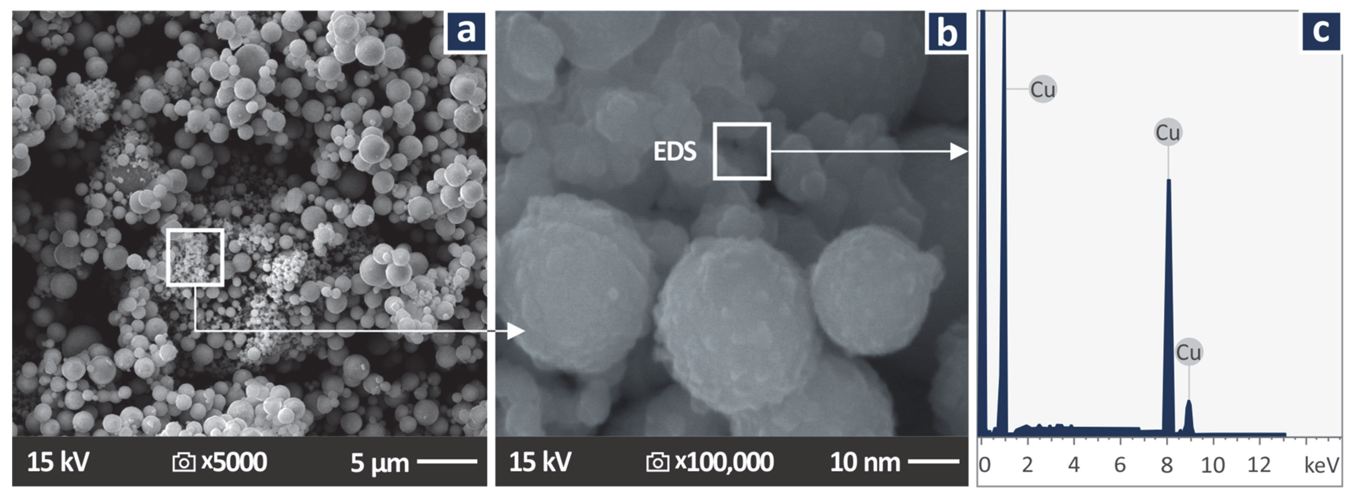
Initially, the Cu nanoparticles were examined with Scanning Electron Microscopy (SEM). A Jeol JSM-IT700HR (Jeol Ltd., Tokyo, Japan) field emission SEM was used. Images were taken on non-sputtered powder, aiming to verify the shape and the size of the nanoparticles. Energy Dispersive Spectroscopy (EDS) analysis was also conducted to verify the elements in the powder.

2.3. Samples Preparation

Herein, samples for the mechanical, thermal, spectroscopic, and antibacterial tests were prepared from three different nano-compounds (Table 1).
Stock biomed amber parts were 3D printed for comparison purposes, with the same 3D printing settings as the nanocomposites. The same package of samples was prepared with the nanocomposites. Nanocomposites with biomed amber as the matrix material and Cu nanoparticles as the filler were prepared at two different concentrations, 0.5 weight-to-weight (wt.%) and 1.0 wt.%, as mentioned. These concentrations were selected, aiming to determine the effect of Cu at low concentrations. For the preparation of the nanocomposites, the raw materials were weighted at the correct proportions and two different mixtures, one for each nanocomposite, were prepared. Each compound was stirred in a high rotational/shear stirrer to ensure the homogeneous dispersion of the Cu nanoparticles in the biomedical resin, i.e., to produce a grade consistent suspension for both the 0.5 wt.% and 1.0 wt.% filler concentrations. The process followed for the preparation of the nanocomposites is compatible with the literature for the preparation of composites for the VPP process [106,107,108].
Then, each suspension was put in an air vacuum devise in order to be degassed. Each resin/nanocomposite afterward filled properly in the tank of the VPP 3D printer device to produce the corresponding 3D printing samples. A Formlabs Form 3B (Formlabs Ohio Inc., Millbury, OH, USA) VPP 3D printer was used for the fabrication of the samples. Tensile (type V specimens with 3.2 mm height, according to the ASTM D638-14 international standard) and flexural specimens (according to the ASTM D790-10 international standard) were 3D printed, along with cylindrical specimens (ø12 mm × 4 mm) for the antibacterial tests. Six specimens were fabricated in each case. Specimens were built at 45 degree angles to the build platform. The 3D printing settings were selected according to the default settings of the 3D printer for this specific resin to achieve good quality parts (layer thickness 0.05 mm). After the completion of the build process, parts were washed in a Formlabs Form Wash machine (Formlabs Ohio Inc., Millbury, OH, USA) for 20 min. A Formlabs Form Cure (Formlabs Ohio Inc., OH, USA) machine was used for the curing of the parts, according to the manufacturer’s instructions and the literature on the specific resin [27].

2.4. Thermal and Spectroscopic Analysis

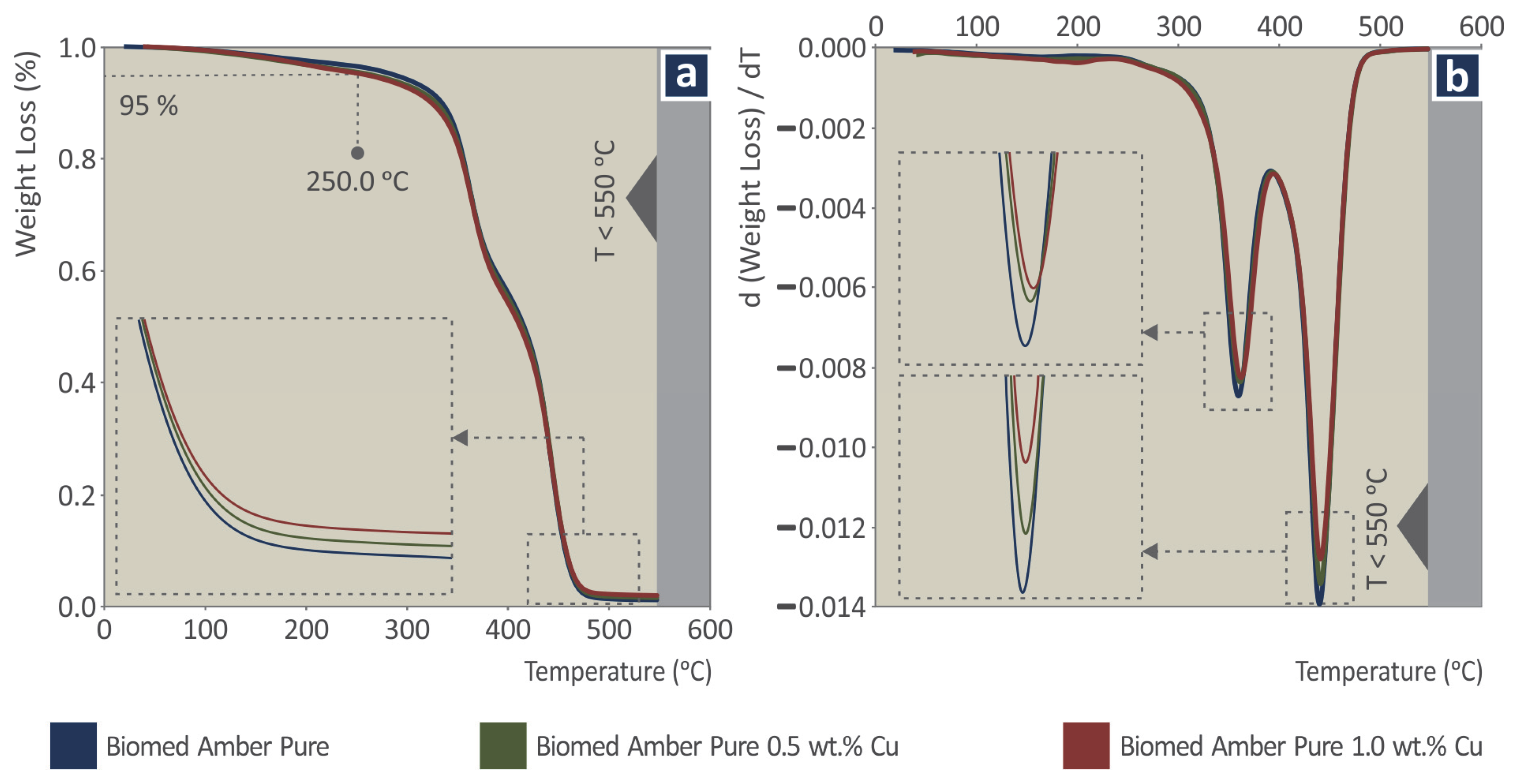
Thermogravimetric analysis (TGA) measurements (Perkin Elmer Diamond, Perkin Elmer Inc., Waltham, MA, USA, 30–550 °C, step 10 °C/min, a Nitrogen atmosphere) were taken on samples of approximately 10 mg, taken from the 3D printed samples, to determine the thermal properties and stability of the produced nanocomposites.
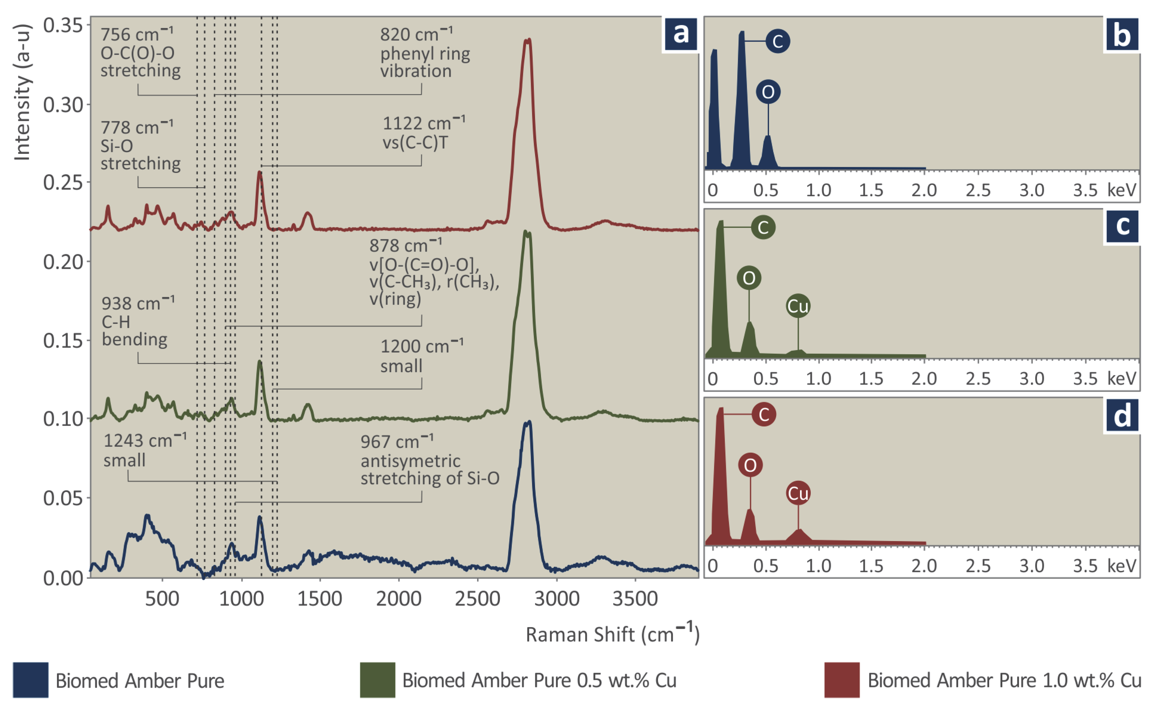
Raman measurements were performed with a modified LabRAM HR Raman Spectrometer (HORIBA Scientific, Kyoto, Japan). Raman excitation was achieved with a 532 nm central wavelength solid-state laser module with a maximum laser output power of 90 mW. The microscope is coupled with a 50× microscopic objective lens with a 0.5 numerical aperture and 10.6 mm working distance (LMPlanFL N, Olympus) that delivered the excitation light and collected the Raman signals. A neutral density filter of 5% transmittance was used, which resulted in 2 mW of power on the sample. The laser spot size was approximately 1.7 μm laterally and approximately 2 μm axially. A 600 grove grating was used, resulting in a Raman spectral resolution of approximately 2 cm−1. The Raman spectral range was set to be from 500 to 3900 cm−1, resulting in 3 optical windows per point. The acquisition time for each measurement was 10 s and with five accumulations at each point.

2.5. Quality Characteristics and Mechanical Characterization

For the evaluation of the quality of the 3D printed parts, surface roughness measurements were taken in the longitudinal and the vertical direction with a Taylor Hobson surtronic3+ (Taylor Hobson, Leicester, UK) roughness gage device. A common issue in parts made with VPP is the shrinkage of the parts [4,25,26,27], therefore the dimensions of the section of the tensile parts in the middle of the part were measured with a high-quality caliper, and the effect of the control parameters (Cu concentration in the nanocomposites and 3D printing direction) studied in the work was evaluated.
For the evaluation of the control parameters in the mechanical strength of the 3D printed parts, tensile and flexural tests were conducted. Experiments were carried out on an Imada MX2 (Imada Inc., Northbrook, IL, USA) machine, according to the corresponding standards (ASTM D638-14 for the tensile tests and ASTM D790-10 for the flexural tests). In each type of experiment, the machine had a suitable setup for the test. In the tensile tests, standardized grips were used, while in the flexural tests, a three-point-bending setup was used with a 52 mm span, following the corresponding standard. Elongation speeds were set at 10 mm/min and experiments were carried out at room temperature. Five specimens were tested in each type of experiment, out of the six manufactured in the VPP 3D printing process.

2.6. Morphological Examination

The 3D printed specimens’ morphological characteristics were examined with an optical stereoscope (KERN OZR5, equipped with a KERN ODC 832 5MP camera, KERN & SOHN GmbH, Balingen, Germany) and a Jeol JSM-IT700HR (Jeol Ltd., Tokyo, Japan) field emission SEM. Images were taken on the side of the tensile specimens, to evaluate the 3D printing quality and to locate possible defects. The fracture surface of tensile specimens was also inspected with the same SEM at different magnifications to evaluate the fracture mechanism and to locate possible agglomerations of Cu in the nanocomposites.

2.7. Design of Experiment, Statistical Analysis, and Optimization of the Experimental Results

For the analysis and optimization of the experimental findings a 3 × 3 full factorial array was formed. The control parameters were the Cu concentration in the materials and the 3D printing angle of the samples, with three levels each (Table 2). The response parameters were related to the quality characteristics of the samples, i.e., cross-sectional area (mm2) and its (%) deviation to the nominal value; average surface roughness Ra (μm) in the horizontal and in the vertical direction; and surface roughness Rz (μm) in the horizontal and in the vertical direction, as well as to the mechanical properties of the samples, i.e., tensile strength (MPa), the tensile modulus of elasticity (GPa); tensile toughness (MJ/m3); flexural strength (MPa); the flexural modulus of elasticity (GPa); and flexural toughness (MJ/m3). Results were statistically analyzed, an Analysis of Variances (ANOVA) followed, and modeling equations were produced. The effect of the control parameters in the response parameters is presented and analyzed further down in the work in the results section.

2.8. Antibacterial Performance of the Nanocomposites

A screening agar well diffusion method was used to evaluate the ability of the Cu nanoparticles to induce antibacterial properties in the biomed amber resin, with the process followed for the development of the nanocomposites. The negative control in the work was the sample made with pure biomed resin. The positive controls for the biological experiment were the samples made with the two nanocomposites in the work (nanocomposite with 0.5 wt.% and 1.0 wt.% Cu nanoparticles concentration).
The McFarland Standard 0.5 was followed in the work. The biocidal performance of the nanocomposites was tested against Gram-positive Staphylococcus aureus (S. aureus) and Gram-negative Escherichia coli (E. coli) bacteria. Bacteria we certified and sourced by the local microbiologist’s association (Hellenic Cooperative of Laboratory Doctors—MEDISYN, Athens, Greece, https://www.medisyn.eu/en/homepage, accessed on 1 November 2022). The 3D printed nanocomposites (with cylindrical shape and dimensions Ø12 mm × 4 mm) were placed in two types of 85 mm Petri dishes, each having suitable growth material for each bacterium. Bacterium growth was performed at 37 °C for 24 h. The ability of the nanocomposites prepared in the work to inhibit growth of the bacteria was evaluated by the inhibition zones (IZ) developed on the Petri dishes after the 24 h period. The IZ was measured with an optical microscope (Kern OKO 1, equipped with a KERN ODC 832 5MP camera, KERN & SOHN GmbH, Balingen, Germany).

3. Results

3.1. Copper Nanoparticles Inspection

Figure 2 presents SEM images taken on the powder used as the additive in the work (Cu nanoparticles). In the images taken, the shape and the size of the nanoparticles were verified, with only very few nanoparticles observed with dimensions higher than the manufacturer’s specs. Figure 2c presents the Energy Dispersive Spectroscopy (EDS) graph produced by examining the region shown in Figure 2b. As expected, high peaks of the Cu element are shown, indicating a high concentration of the element in the observation region.

3.2. Thermal and Spectroscopic Analysis

Figure 3a presents the weight loss vs. temperature graph for each one of the materials studied in the work (stock biomed amber and biomed amber/Cu nanocomposites at two Cu concentrations), as they were produced in the thermogravimetric analysis (TGA) measurements, that is, the degradation of the material (loss of the mass) with the increase in the temperature, as it was derived from the TGA measurements. From the graphs, it is shown that the materials have a similar thermal response. The degradation of the materials starts at approximately 250 °C. The thermal stability of the biomed amber resin was not affected by the addition of the Cu nanoparticles. The remaining material quantities after the completion of the measurements agree with the concentration of the Cu additive in the corresponding nanocomposites. Figure 3b presents the corresponding weight loss rate vs. temperature graphs, i.e., how fast the mass degradation occurred in the experiment and how this rate changes with the increase of the temperature. The maximum weight loss rate occurs at roughly the same temperature for all materials. The weight loss rate decreases with the increase of the Cu loading in the nanocomposites, with the lowest value depicted for the 1 wt. % Cu nanocomposite. This is the expected response, as with the increase of the Cu loading, the mass that does not degrade during the TGA measurement increases. The remaining mass after the completion of the TGA measurements agrees with the Cu concentration in each nanocomposite.
As is seen in Figure 4, the major Raman peaks are from amber pure. The addition of Cu in amber samples presented a gradual drop in the photoluminescence together with an increase in the density of Cu particles. This caused a clearer Raman signal in the range between 500 and 1300 cm−1. From the analysis of amber pure, the major Raman peaks are identified, and their related assignments are presented in the following Table 3. The range of the Raman peaks found is between 500 cm−1 and 3000 cm−1. The Si-O peaks are from the resin since they appear in all the observations in the work. Throughout the analysis, the main compositional influence is the addition of the Cu, which at such small concentrations does not affect the observed peaks in the Raman spectra, with changes in the small peaks being marginal. It should be noted that there was no visible or measurable effect from the laser irradiation on the sample, during Raman signal acquisition.
The following Raman peaks increased with the addition of Cu particles, most probably due to the photoluminescence signal drop, and are shown in the next Table 4.

3.3. Mechanical Characterization

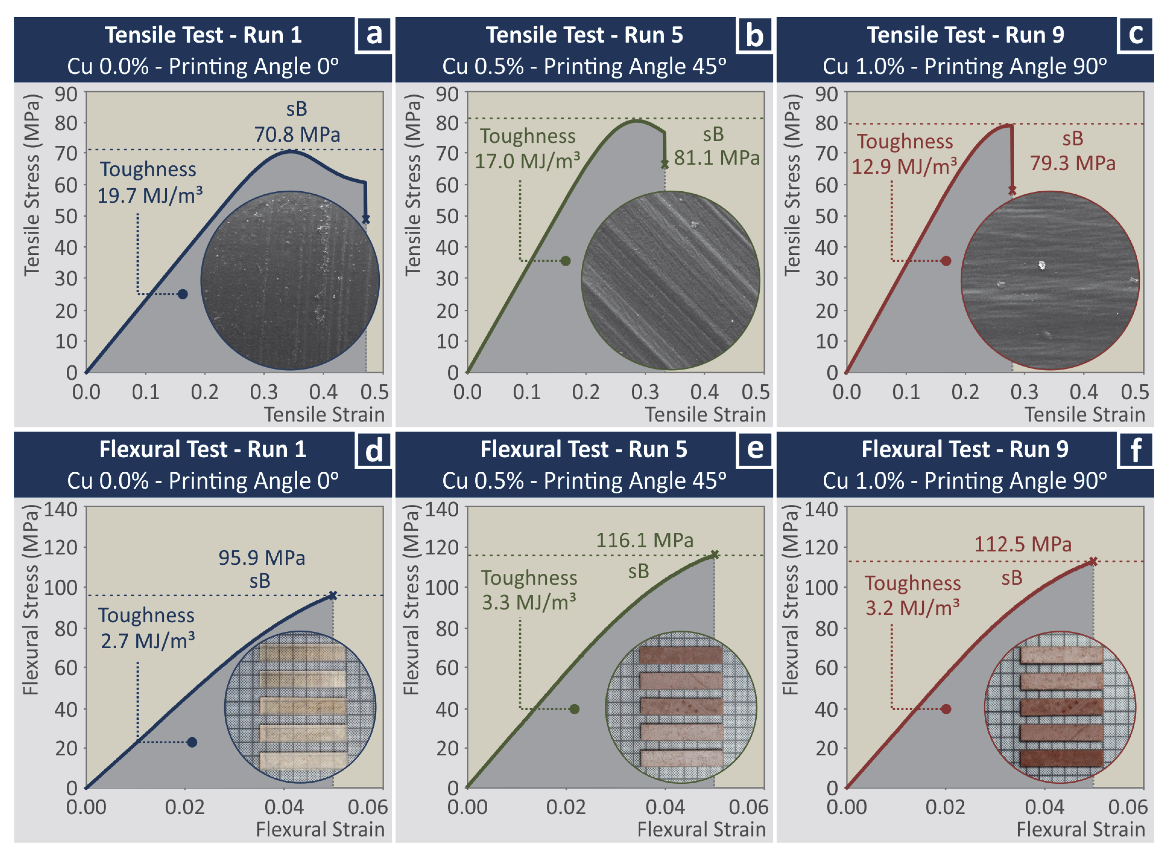
As mentioned, for the mechanical characterization of the nanocomposites, tensile and three-point bending flexural tests were carried out. Five specimens were tested for each different case studied (levels of wt.% concentration and printing angle—PA). Figure 5 presents a typical graph of a randomly selected specimen from each different sample studied (wt.% concentration and printing angle—PA). Tensile and flexural stress vs. strain graphs is presented, which were produced during the experiments. The purpose of Figure 5 is to show one of the five graphs produced in each test for three samples prepared with different parameters (first run, middle run, and last run). The aim is to show the effect of the different control parameter values on the mechanical behavior of the nanocomposites and how the different nanocomposites behave in the mechanical tests. In the inset images in the figures, microscope images from the side of the samples indicating the PA of the specimen presented in the corresponding graph are shown. In the curves produced in the flexural tests, randomly selected specimens are shown. The corresponding toughness values calculated as the integral of the stress vs. strain graph are also mentioned in each graph. The average mechanical properties calculated for each case from the experiments are presented in the statistical analysis section of the work in comparison with the corresponding control parameters.

3.4. Morphological Examination

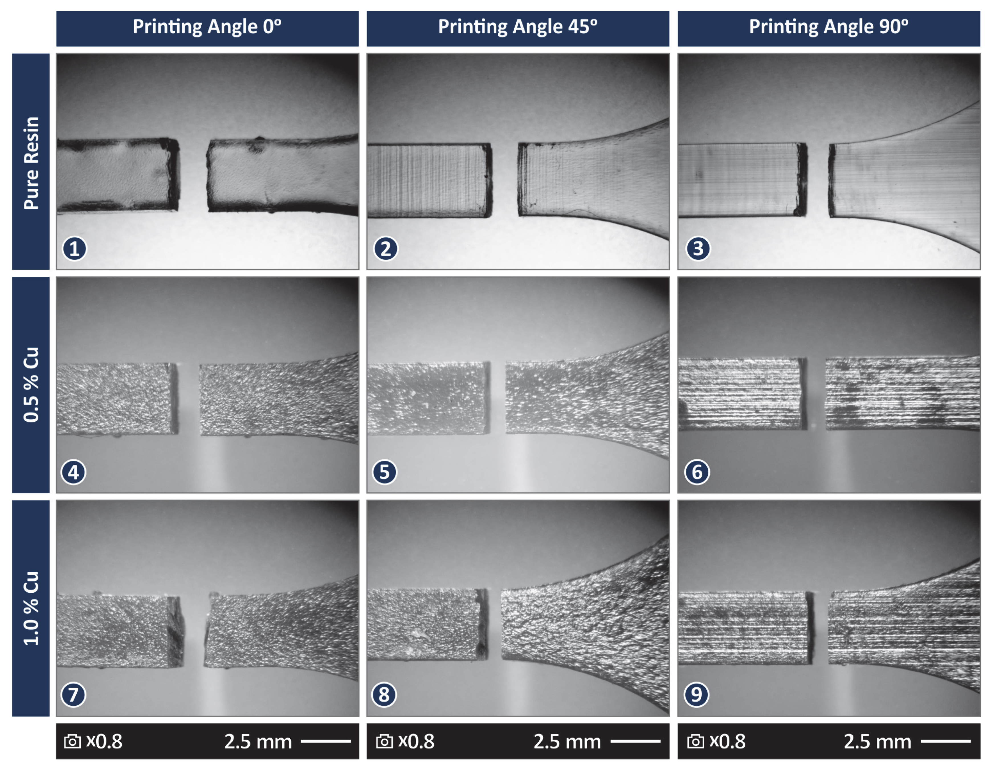
Figure 6 presents stereoscopic images from the top of the tensile samples after they fail the tests. One random sample from each different case study is presented. From the images, a qualitative evaluation can be made. The samples manufactured with the stock biomed amber material show slightly higher deformation in their fracture area when compared with the samples made with the nanocomposites, still a brittle failure is observed. This agrees with the stress vs. strain graphs presented in Figure 5. Regarding the quality of the surface, visually in the images, the samples made with the stock biomed amber material are less rough than the samples made with the nanocomposites. The samples made with the nanocomposite with 0.5 wt.% Cu show the roughest surfaces among the samples tested.
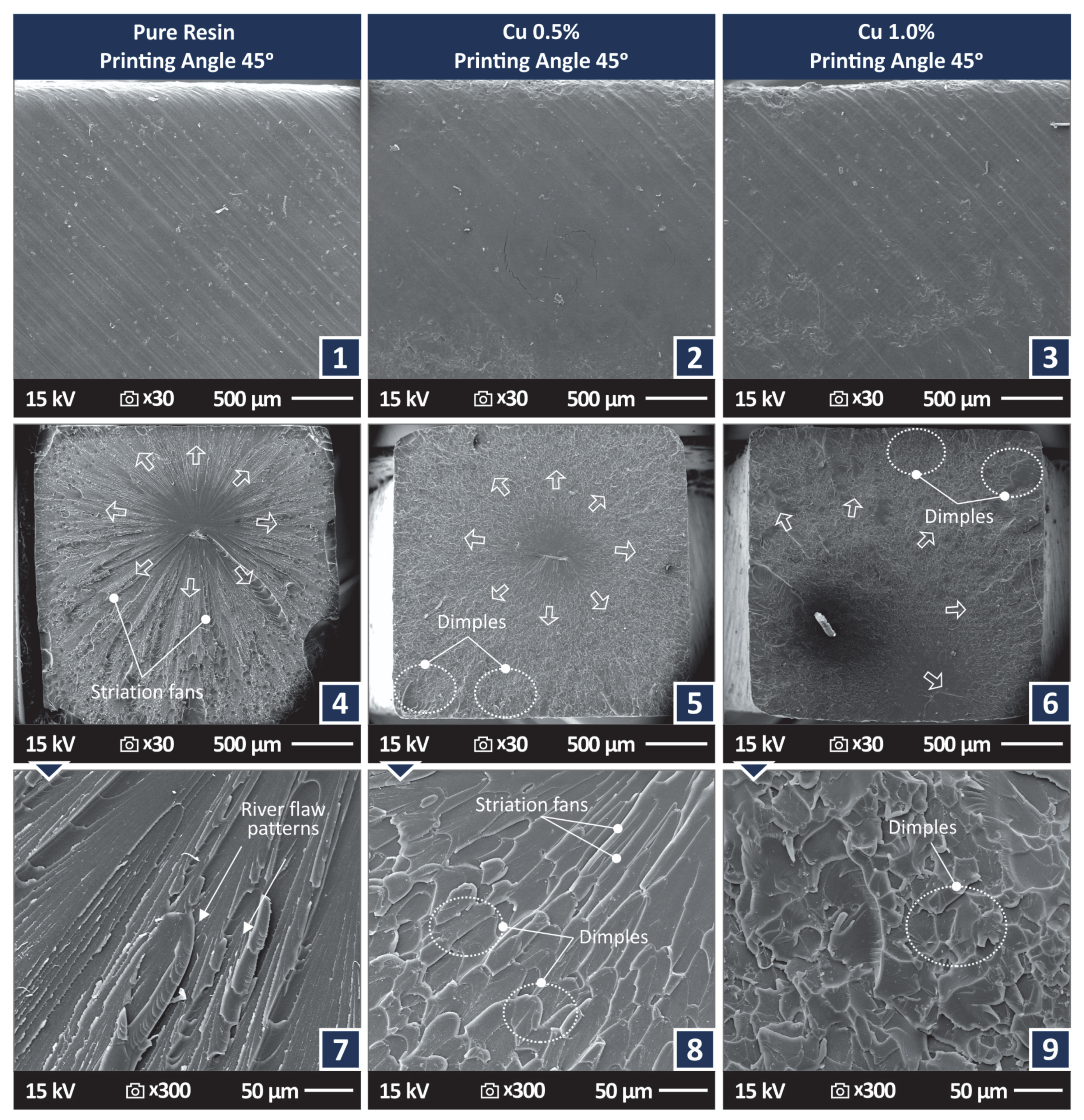
Figure 7(1)–(3) present side surface SEM images from tensile samples 3D printed with 45 degree angles with the different materials tested. The PA can be observed in the SEM images. In all samples, a 3D printing structure with no defects or voids can be observed. The remaining images of Figure 7 present the corresponding fracture area images for the aforementioned samples of Figure 7 at two different magnifications. In all samples, the evolution of the fracture during their failure is observed and indicated in the figures. The characteristic striation lines, river flow pattern, and dimples of the polymers in vat photopolymerization are observed in the figure [116].
For the sample made with the stock biomed amber material and the sample made with the 0.5 wt.% nanocomposite, the fracture started at approximately the center of the samples’ cross-section area. For the sample made with the 1.0 wt.% nanocomposite, the fracture start was off-centered. In the higher magnification images, the fracture area of the sample made with the stock biomed amber material (Figure 7(7)) shows some deformation, while the samples made with the two nanocomposites show a more brittle fracture mechanism, which agrees with the experimental graphs and the observations in the optical stereoscope.
Figure 8 shows higher magnification SEM images of 45,000× for the two nanocomposites studied. Images were also taken on the fracture surface of the tensile test samples. In these nanoscale images, no agglomerations were located in the samples, while nanoparticles were identified. Additionally, nano-cracks on the samples were spotted in the fracture area, showing somehow that the failure of the specimen was not restricted only to the fracture area, but also slightly diffused in the remaining sample’s structure. Energy Dispersive Spectroscopy (EDS) graphs were produced by analyzing regions of the fracture area in which nanoparticles were observed (Figure 8c). The EDS graphs verified the existence of nanoparticles, as the peaks of the Cu element in the produced graphs were high, indicating a high concentration of the element in the observed regions. No unexpected elements were identified in the EDS graphs and no nanoparticles agglomerations were located.

3.5. Statistical Analysis and Optimization of the Experimental Results

Table 5 and Table 6 present the average values and the deviation for the response parameters of the study related to the quality characteristics and the mechanical properties, respectively, for each experimental run. The analytic experimental results are presented in Tables S1 and S2 of the Supplementary material.
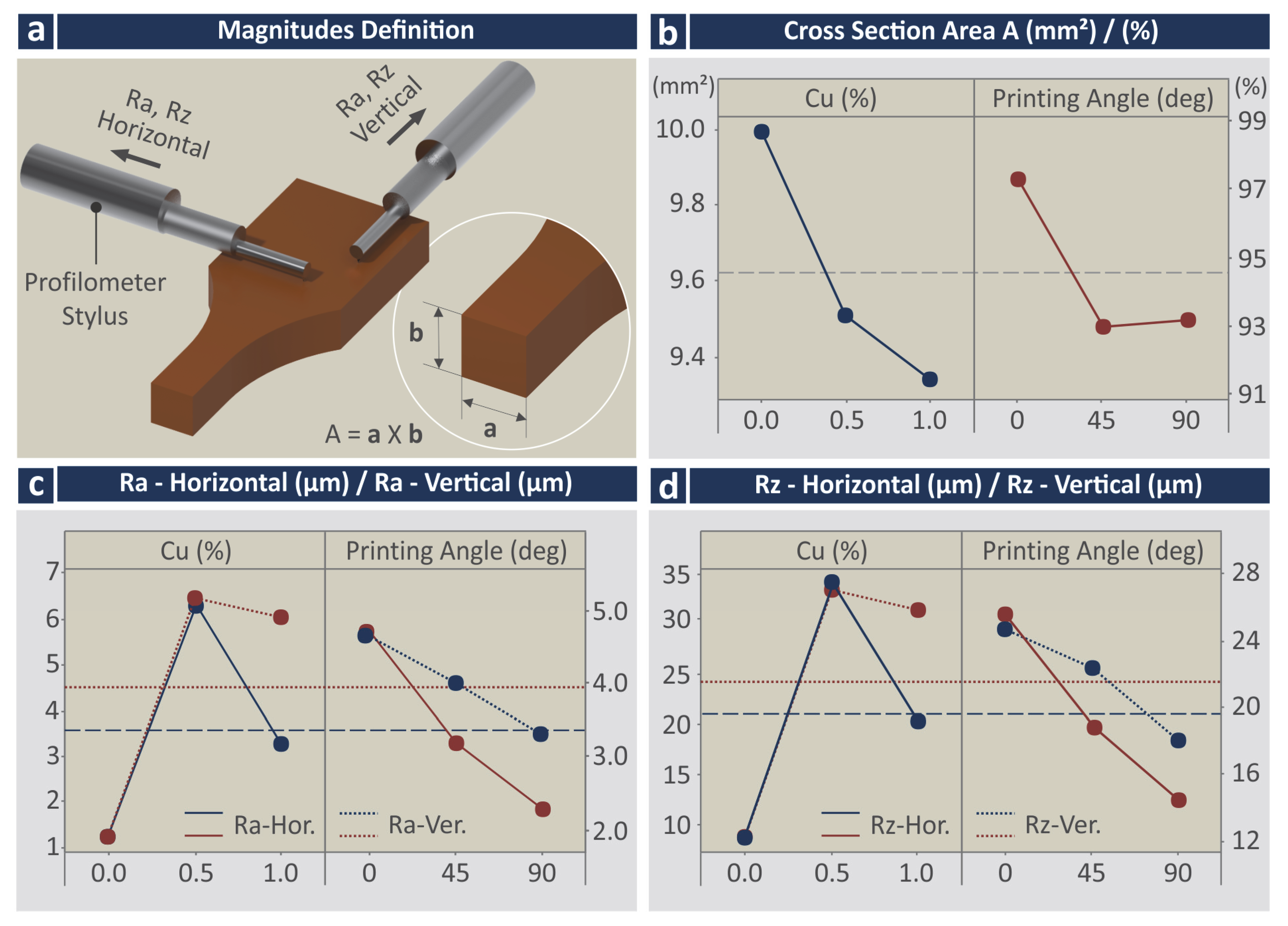
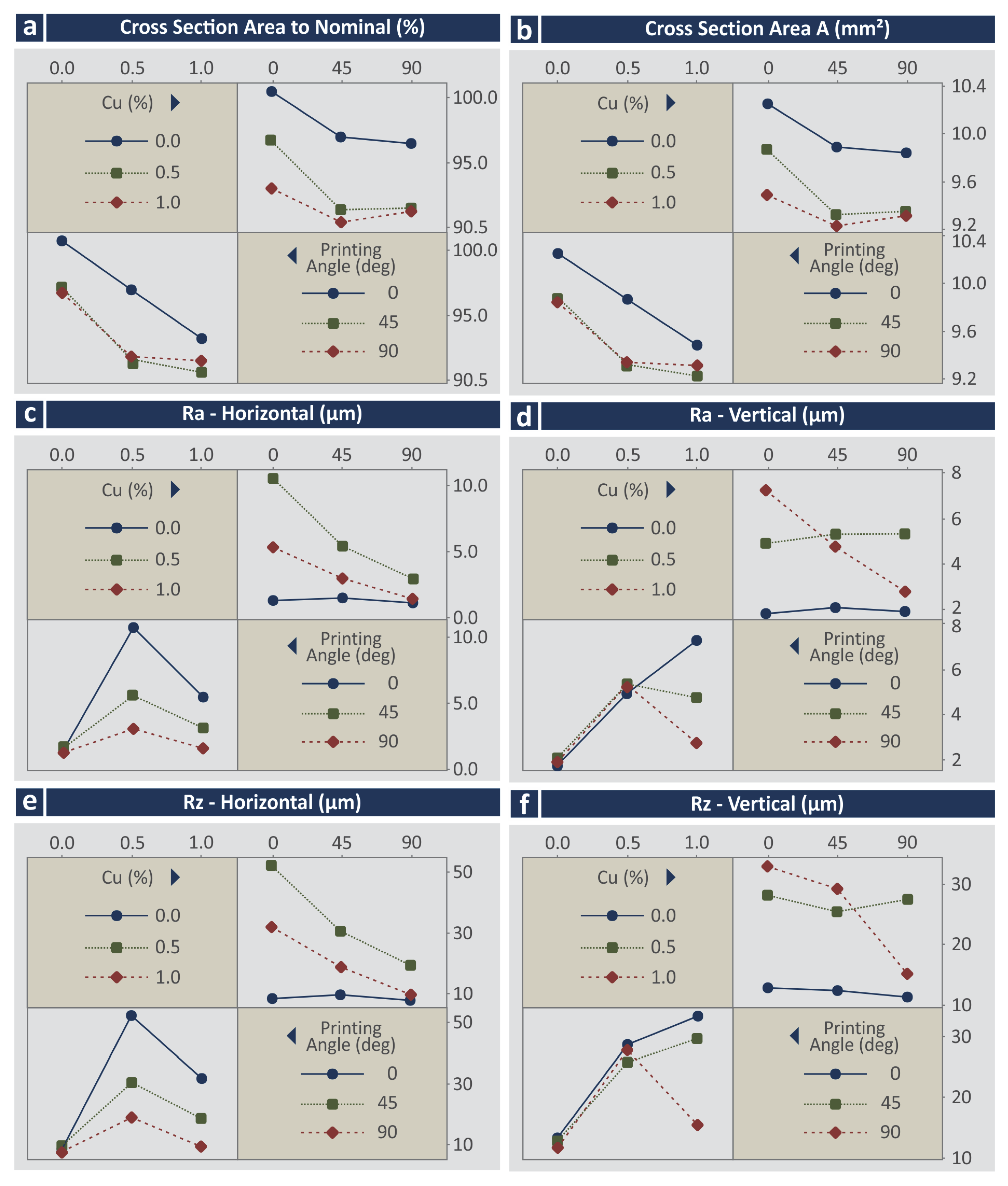
Figure 9 presents the Main Effect Plots (MEPs) for the response parameters related to the quality characteristics of the 3D printed specimens. Figure 9a illustrates how the surface roughness measurements were taken and what was measured for the cross-section area calculation in the specimens (measurements were taken with a high-quality caliper). It should be mentioned that VPP 3D parts exhibit shrinkage issues, so it was not expected to measure the dimensions of the manufactured parts higher than the nominal. Shrinkage occurred in both directions measured in the section area (not in the same amount).
In the MEPs for the cross-section area and the (%) deviation from the nominal value (Figure 9b), it can be observed that the shrinkage of the specimens is increased with the increase of the Cu concentration on the materials. Regarding the printing angle (PA), the specimens built with 0 degrees PA depict the lowest shrinkage, while the specimens built with a PA of 45- and 90-degrees depict increased shrinkage values. Regarding the surface roughness Ra, samples built with the stock biomed amber material exhibited the lowest Ra values in both measured directions, while samples built with the 0.5 wt.% Cu concentration nanocomposite exhibited the highest Ra values in both measured directions. Samples built with the 1.0 wt.% Cu nanocomposite show decreased values, but still higher than the samples built with the 0.5 wt.% Cu concentration nanocomposite. This agrees with the findings from the visual inspection of the samples in the optical stereoscope (Figure 6). Surface roughness measurements follow the same trend regarding their values in both measured directions. Regarding the surface roughness Ra vs. the PA, the 0 degrees sample showed the highest Ra values, with Ra decreasing with the increase of the PA. The same trend and observations can be made regarding the values of the measured surface roughness Rz (Figure 9d).
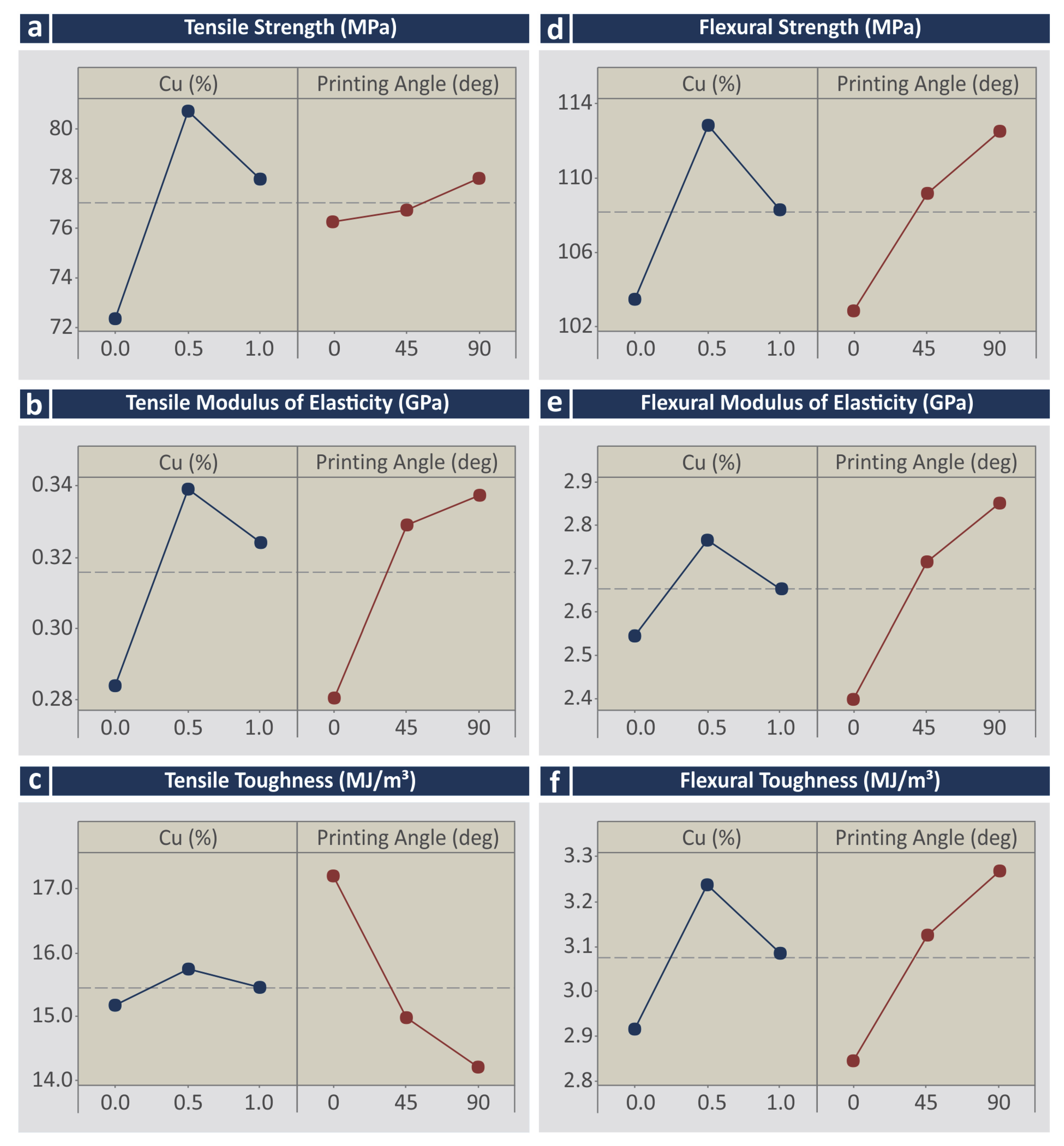
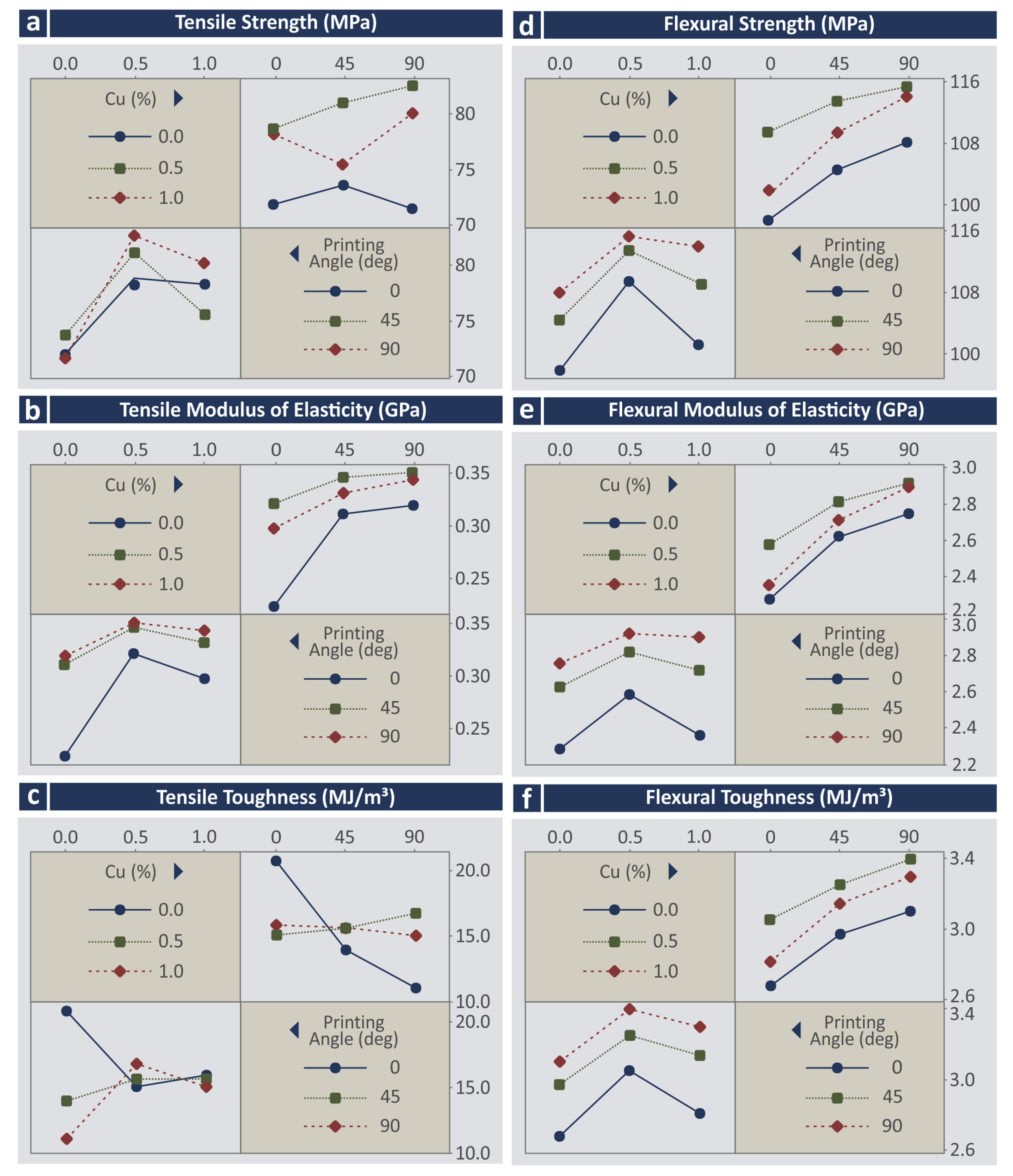
The corresponding MEPs for the response parameters related to the mechanical properties of the 3D-printed specimens are presented in Figure 10. As it can be observed, all of the response parameters (tensile strength—MPa, the tensile modulus of elasticity (GPa), tensile toughness (MJ/m3), flexural strength (MPa), the flexural modulus of elasticity (GPa), and flexural toughness (MJ/m3) follow the same trend regarding the Cu concentration on the materials. The addition of Cu increased the mechanical properties, with the highest improvement observed on the samples built with the 0.5 wt.% Cu concentration nanocomposite. The samples built with the 1.0 wt.% Cu concentration nanocomposite exhibited reduced mechanical properties that were still higher than the samples built with the stock biomed amber material. PA has no significant effect on tensile strength (Figure 10a). The increase of PA increases the tensile modulus of elasticity (GPa) (Figure 10b), the flexural modulus of elasticity (GPa) (Figure 10e), and the flexural toughness (MJ/m3) (Figure 10f), while it reduces the tensile toughness (MJ/m3) (Figure 10c).
To evaluate the synergistic and antagonistic mechanisms of the control parameters, the corresponding interaction plots were compiled (Figure 11 and Figure 12). Regarding the response parameters related to the quality characteristics of the specimens (Figure 11), in most cases, synergistic interactions can be observed between the control parameters. Only in the cases of Ra and Rz measured in the vertical direction were antagonistic relations found. The interaction plots for the mechanical properties vs. the control parameters (Figure 12) revealed antagonistic interactions for most of the tensile properties, except the tensile modulus of elasticity vs. Cu (%) in which synergistic relations were observed. For the flexural properties, synergistic relations among the control parameters were observed.

3.6. Regression and ANOVA

The Reduced Quadratic Regression Model (RQRM) for each response is calculated, according to the following Equation (1):
Y k = a k + i = 1 n b i , k x i + i = 1 n c i , k x i 2 + e k
where k represents the quality output (e.g., tensile strength, tensile modulus of elasticity, tensile toughness, flexural strength, flexural modulus of elasticity, flexural toughness, tensile specimen measured area, tensile specimen area to nominal area, horizontal and vertical Ra and Rz roughness), a is the constant value, b the coefficient of the linear terms, c the coefficients of the quadratic terms, e the error and xi the two (n = 2) control parameters, i.e., the input 3D printing independent variables.
The ANOVA table for each of the response parameters vs. the control parameters is presented in Tables S3–S14 in the Supplementary Materials of the work. In most cases, the regression values are close to or even higher than 80%, while in the case of the flexural modulus of elasticity (GPa), the flexural toughness (MJ/m3), the cross-section area (mm2), and the cross-sections area deviation (%), the regression values are higher than 90%, indicating that the models are adequate for the prediction of the corresponding response parameters. Only in the case of the tensile toughness (MJ/m3) are the regression values low (~36%), indicating that in this case the model failed to predict the response parameter and cannot be considered reliable for such calculations. For each response parameter, an equation was formed as a function of the control parameters and the equations are presented below:
A r e a _ T e n s i o n = 10.3053 1.403 · % Cu   0.01445 · PA   + 0.630   · % Cu 2 + 0.000100 · PA 2 + 0.002617 · % Cu · PA
A r e a _ 2 _ N o m = 101.270 13.79 · % Cu   0.1420 · PA   + 6.19 · % Cu 2   + 0.000986 · PA 2 + 0.02572 · % Cu · PA
R a _ H o r = 2.465 + 19.92 · % Cu   0.0436 · PA   16.08 · % Cu 2   + 0.000239 · PA 2 0.0422 · % Cu · PA
R a _ V e r = 1.388 + 12.36 · % Cu   + 0.0130 · PA   7.05 · % Cu 2   0.000025 · PA 2 0.05118 · % Cu · PA
R z _ H o r = 13.22 + 100.4 · % Cu   0.168 · PA   78.1 · % Cu 2   + 0.00092 · PA 2 0.2422 · % Cu · PA
R z _ V e r = 11.19 + 53.57 · % Cu   + 0.0617 · PA   31.87 · % Cu 2   0.000502 · PA 2 0.1816 · % Cu · PA
s B _ T e n s i o n = 72.171 + 26.71 · % Cu   0.0109 · PA   22.27 · % Cu 2   + 0.000201 · PA 2 + 0.0250 · % Cu · PA
E _ T e n s i o n = 235.54 + 206.4 · % Cu   + 1.821 · PA   140.5 · % Cu 2   0.00998 · PA 2 0.574 · % Cu · PA [ M 29 ]
T o u g h n e s s _ T e n s i o n     = 19.14 2.56 · % Cu   0.1138 · PA   1.63 · % Cu 2   + 0.000348 · PA 2 + 0.0988 · % Cu · PA
s B _ F l e x u r a l = 98.813 + 31.13 · % Cu   + 0.1568 · PA   27.67 · % Cu 2   0.000711 · PA 2 + 0.0285 · % Cu · PA
E _ F l e x u r a l = 2309.9 + 736.1 · % Cu   + 8.51 · PA   666.7 · % Cu 2   0.0433 · PA 2 + 0.782 · % Cu · PA
T o u g h n e s s _ F l e x u r a l     = 2.7006 + 1.0768 · % Cu   + 0.007251 · PA   0.9417   · % Cu 2 0.000032 · PA 2 + 0.000711 · % Cu · PA
To identify the statistical importance of each parameter, Pareto charts were formed for all the response parameters (Figures S1–S5 of the Supplementary Materials). The following statistically important parameters were found:
  • All parameters for the cross-section area to nominal (%);
  • All parameters for the cross-section area (mm2);
  • Cu, Cu2, and Cu × Deg for the Ra in the horizontal direction;
  • Cu, Cu2, and Cu × Deg for the Ra in the vertical direction;
  • Cu, Cu2, and Cu × Deg for the Rz in the horizontal direction;
  • Cu, Cu2, and Cu × Deg for the Rz in the vertical direction;
  • Cu and Cu2 for the tensile strength (MPa);
  • All parameters for the tensile modulus of elasticity (GPa);
  • Cu×Deg and Deg for the tensile toughness (MJ/m3);
  • Cu, Cu2, and Deg for the flexural strength (MPa);
  • Cu, Cu2, Deg, and Deg2 for the flexural modulus of elasticity (GPa);
  • Cu, Cu2, Deg, and Deg2 for the flexural toughness (MJ/m3).
Additionally, for each response parameter comparative, experimental vs. calculated graphs were formed and the mean absolute percentage error (MAPE) and the Durbin–Watson factor (a measurement indicator of the autocorrelation in the residuals) were calculated to identify the reliability of the equations’ results. In all response parameters, the MAPE calculated values were very acceptable (<2% and in the case of the tensile modulus of elasticity 4.15%), except, as expected the case of the tensile toughness (MJ/m3) in which the calculated MAPE value was higher (15.14%), still within acceptable limits. The calculated Durbin–Watson factors ideally should be (>2, <3) and that was the case for most response parameters, or values lower but close to 2 were calculated, which is acceptable for all response parameters.
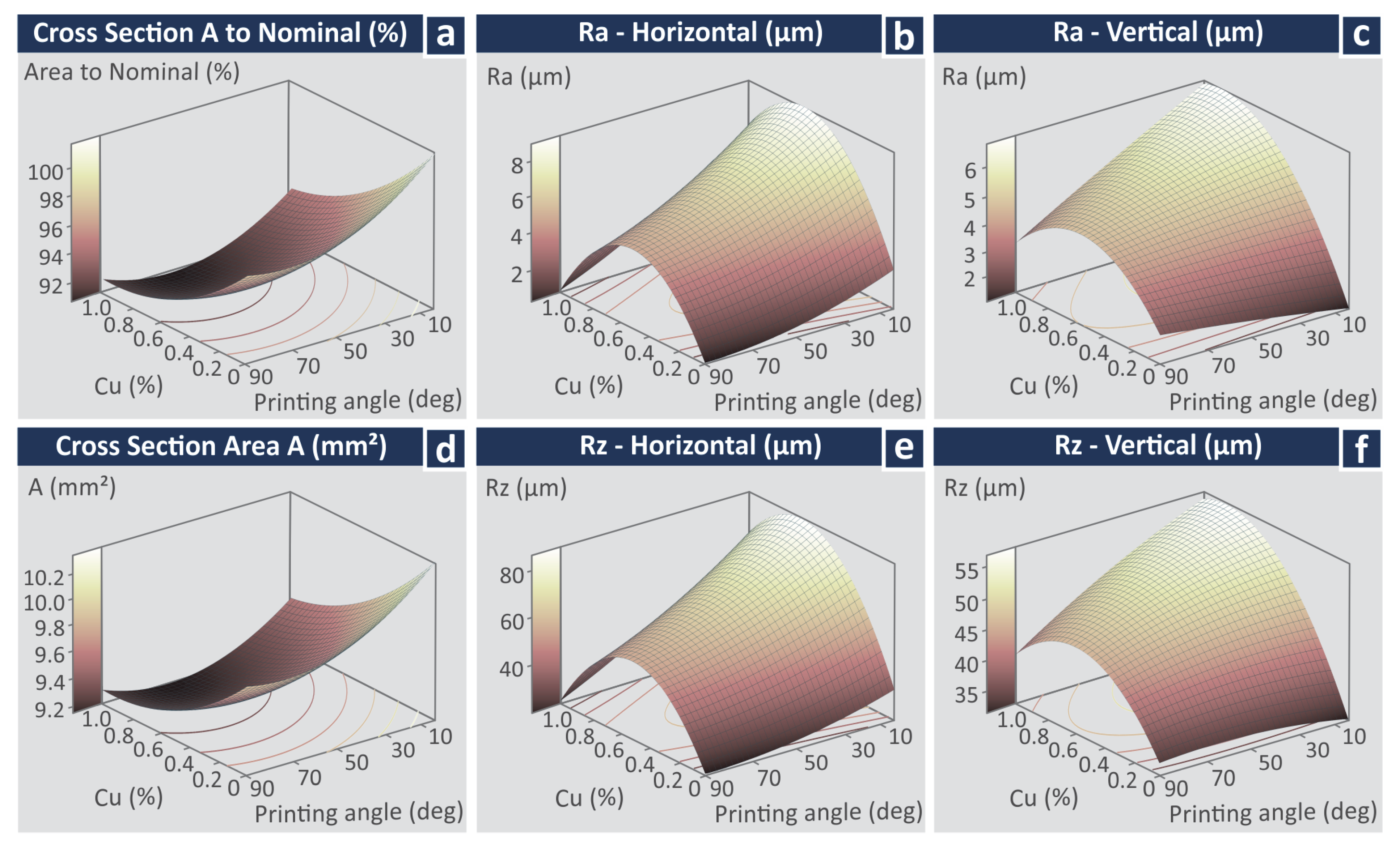
Figure 13 and Figure 14 present the experimental findings of the work as surface graphs for the response vs. the control parameters studied. Figure 13 contains the surface graphs for the response parameters related to the quality characteristics of the samples, while Figure 14 depicts the response parameters related to the mechanical properties vs. the control parameters.

3.7. Antibacterial Performance of the Nanocomposites

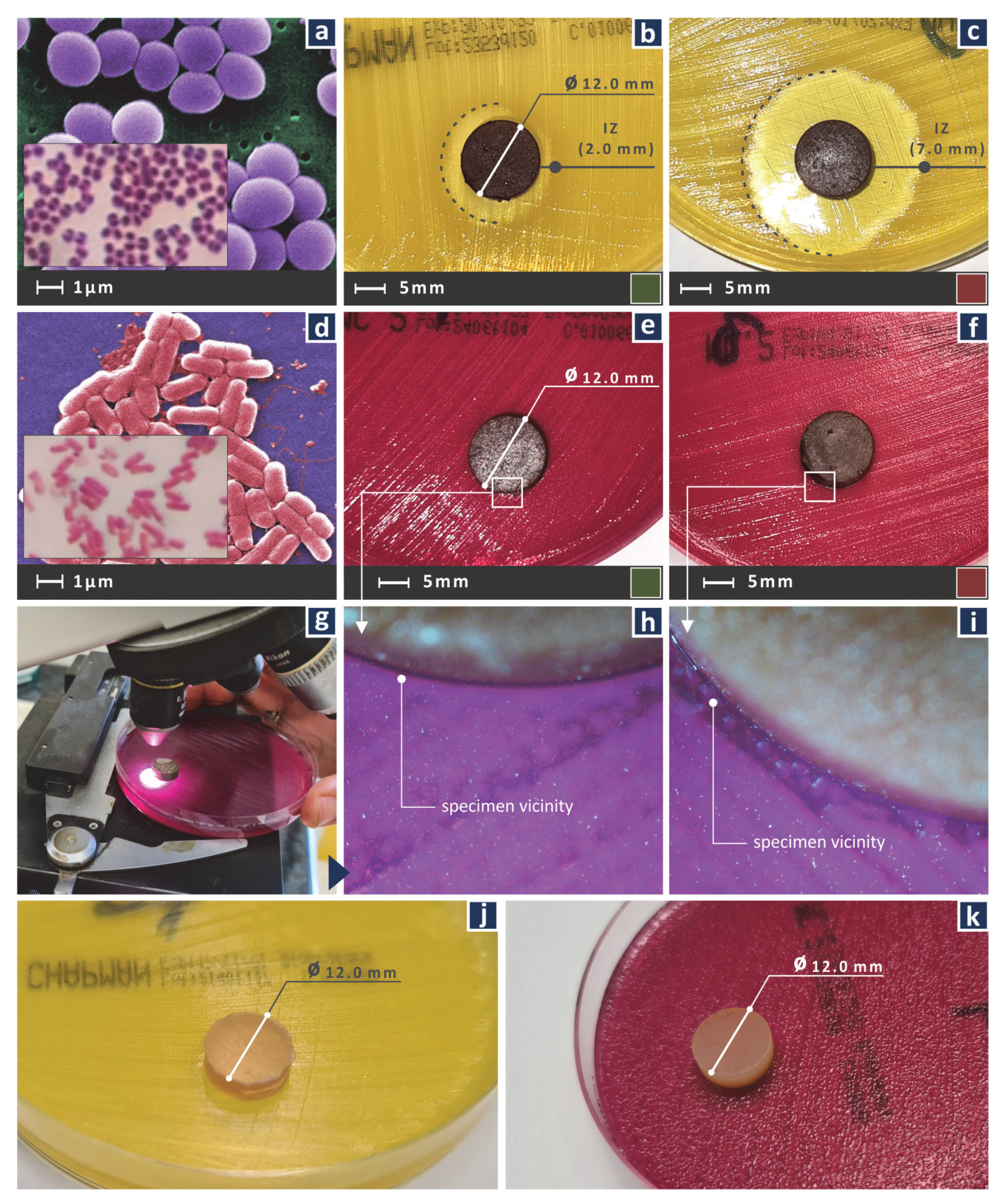
Figure 15 shows the results from the screening agar well diffusion test in the samples for the two bacteria tested, i.e., Gram-positive S. aureus and Gram-negative E. coli. More specifically, the developed inhibition zones (IZ) in the tests are presented. For the Gram-positive S. aureus, adequate width IZ was developed. As expected, the sample with the 1.0 wt.% Cu loading inhibited the Gram-positive S. aureus culture more intensively than the sample with 0.5 wt.% Cu loading, developing more than three times wider IZ. Results against Gram-negative E. coli were not as encouraging, with negligible IZ developed in both wt.% Cu loading samples. In Figure 15j the control sample is shown in the S. aureus culture, while Figure 15k shows the corresponding control sample in the E. coli culture. As expected, no inhibition zone was developed in these cases, showing that the IZs developed in the samples made with the nanocomposites were due to the addition of the Cu nanoparticles in the matrix material. Antibacterial test results are summarized in Table 7.

4. Discussion

The aim of this work was achieved. The properties of a commercial medical-grade resin for VPP were enriched, with the addition of Cu nanoparticles and the development of nanocomposites with low filler concentrations. This specific medical-grade resin (biomed amber, Formlabs Ohio Inc., Millbury, OH, USA) has not been investigated in the literature so far, especially for the enhancement of its mechanical properties and an attempt to induce in it antibacterial properties. The outcome of the work is not obvious by works in the literature employing different types of resins with Cu nanoparticles, as the effect of the Cu nanoparticles in the resin could differ. This was verified in the work, as the addition of the same Cu nanoparticles in the Formlabs Standard Clear V4 (Formlabs Inc., Somerville, MA, USA), improved 33.7 % the tensile strength of the resin [44], while in the current work, an improvement was achieved but with lower enhancement effect (11%). Additionally, the addition of the Cu nanoparticles induced a more effective antibacterial performance for both S. aureus, and E. coli bacteria in the Formlabs Standard Clear V4 (Formlabs Inc., Somerville, MA, USA) resin than in the biomed amber resin (Formlabs Inc., Somerville, MA, USA). If the antibacterial performance is the dominant parameter, higher Cu loading provides better results. Such materials can be employed in applications requiring enhanced mechanical performance and antibacterial behavior, further exploiting the advances of vat photopolymerization 3D printing. Such applications can be related to scaffolds and the medical or culinary field for cover parts, among others.
These nanocomposites exhibit a multifunctional performance, with enhanced mechanical properties, compared to the stock medical grade resin and biocidal behavior against two often studied in the literature bacteria. Such materials, according to the literature, are popular for use in scaffolds and devices for medical and culinary use. The low Cu concentration has two main advantages, the cytotoxicity of the materials is expected to be low [74], although no such studies were performed within the context of the work, as it was outside its purposes, and the increase in the cost from the addition of the Cu nanoparticles was negligible. The medical grade resin used cost approximately 350 €/L, which is 1090 g according to its density, so each gram cost 0.32 €. The Cu nanoparticles cost 718 €/Kg, which is 0.718 €/g. For the 0.5 wt.% loading nanocomposite the additional cost of the raw materials was 0.0036 €/g. So, the nanocomposites per gram cost 0.323 €/g, instead of the 0.32 €/g of the stock medical grade resin. Preparation costs need to be considered also, but it is not expected to be significant. These costs can be further reduced for industrial-scale use. Additionally, the thermal stability of the biomed amber was not affected by the addition of the Cu nanoparticles.
The average tensile and flexural strength of the stock biomed amber determined in the experiments agrees with the nominal values of the resin in its technical datasheet. The experimental results of the study cannot be correlated with the literature since no similar materials have been presented so far. Corresponding results with other medical grade resins as matrix materials [58,59] for the development of nanocomposites agree with the findings of the current work. The results of the work also agree with works employing Cu nanoparticles in vat photopolymerization [44,91] and material extrusion (MEX) 3D printing [92,93] for the development of nanocomposites with improved mechanical performance and antibacterial properties. The addition of Cu nanoparticles in the matrix material in these works has a similar effect to the findings of the current work.
The nanocomposites developed in the work exhibited sufficient biocidal performance against Gram-positive S. aureus, while the biocidal performance against Gram-negative E. coli was marginal, which requires further investigation. It can be attributed to the screening process followed and standardized methods should be applied for more solid conclusions regarding the antibacterial performance of the current work’s nanomaterials. In the work, minimum inhibitory concentration (MIC) analysis was not conducted, as it was outside the purposes of the work. This was not carried out since even the 0.5 wt.% concentration is very limited and lower concentrations would not be able to enable adequate mechanical reinforcement of the nanocomposites.
Apart from the antibacterial properties of the nanocomposites, the performance of the nanocomposites prepared herein was evaluated by two different categories of response parameters, i.e., parameters related to the quality characteristics of the 3D printed samples (dimensional accuracy and surface roughness) and parameters related to their mechanical performance (tensile and flexural mechanical properties). Two control parameters were used with three levels each and statistical modeling tools were employed, revealing the effect of each parameter and the relations between the parameters. These tools contributed to the analysis and optimization of the parameters studied. In the work, volumetric analysis was not conducted. Using the information from the actual to nominal deviation and the area measurements, volumetric information can be derived. This work focused on the measurements of the dimensions of the cross-section area and the analysis of any deviations, due to the 3D printing process, as the area of the samples affects the mechanical properties of the parts.

5. Conclusions

In this work, for the first time in the literature, a commercial medical-grade resin for VPP was reinforced with Cu nanoparticles at low concentrations, aiming also to induce antibacterial properties in the prepared nanocomposites. The aim of the work was achieved regarding the mechanical properties of the nanocomposites and partially achieved regarding the antibacterial properties. The nanocomposites inhibited the culture of the Gram-positive S. aureus, while they negligibly inhibited the culture of Gram-negative E. coli bacterium, with the process employed. The nanocomposites developed were also cost-efficient, with a multifunctional character. The nanocomposite with the 0.5 wt.% Cu loading achieved the highest mechanical performance (11% increase in the tensile strength and approximately 10% in the flexural strength), indicating that even at low concentrations the effect on the mechanical properties can be important.
The statistical analysis tool employed optimized the process and showed that both control parameters studied, i.e., wt.% Cu loading and 3D printing angle (with three levels each) have a significant effect on the two types of response parameters studied, i.e., quality parameters related to the quality of the 3D printed parts and parameters related to the mechanical properties of the materials. Following the statistical analysis, optimal dimensional accuracy is achieved with unfilled resin and 0 degrees printing angle. Optimal surface quality is achieved with unfilled resin and 90 degrees printing angle. When there is a demand for enhanced mechanical properties, nano-compounds with 0.5 wt.% Cu loading should be used, which achieved the highest mechanical response, and parts should be built with 90 degree angles.
From the regression analysis, in most cases, except for the tensile toughness (MJ/m3), the modeling proved reliable. Equations, providing reliable results, were prepared as functions of the control parameters, with direct industrial use for the calculation of the 11 response parameters studied, related to quality characteristics and the mechanical properties of the materials prepared in the work. According to the requirements of each application, specific response parameters can be optimized, while the others can be predicted so that the users can have an estimation of what values to anticipate. In future work, additional control parameters can be evaluated, the control parameter levels can be changed, and further studies related to the antibacterial performance of the nanocomposites prepared in this study can be conducted.

Supplementary Materials

The following supporting information can be downloaded at: https://www.mdpi.com/article/10.3390/jfb13040258/s1, Figure S1. Pareto chart and experimental vs. calculated (predicted) graph, for (a) tensile strength (MPa), (b) tensile modulus of elasticity (GPa), (c) tensile toughness (MJ/m3), Figure S2. Pareto chart and experimental vs. calculated (predicted) graph, for (a) flexural strength (MPa), (b) flexural modulus of elasticity (GPa), (c) flexural toughness (MJ/m3), Figure S3. Pareto chart and experimental vs. calculated (predicted) graph, for (a) cross-section area to nominal (%), (b) cross-section area (mm2), Figure S4. Pareto chart and experimental vs. calculated (predicted) graph, for (a) surface roughness Ra in the horizontal direction (μm) (b) surface roughness Ra in the vertical direction (μm), (c) surface roughness Rz in the horizontal direction (μm) (d) surface roughness Rz in the vertical direction (μm), Table S1. Measured Tensile Strength, Tensile Modulus of Elasticity, Tensile Toughness, Flexural Strength, Flexural Modulus of Elasticity, and Flexural Toughness for each experimental run and five replicas per run, Table S2. Measured Tensile Specimen Area, Tensile Specimen Area to Nominal Area, Horizontal and Vertical Ra and Rz Roughness for each experimental run and five replicas per run, Table S3. Polynomial ANOVA, Tensile Strength vs. %Cu, PA., Table S4. Polynomial ANOVA, Tensile Modulus of Elasticity vs. %Cu, PA., Table S5. Polynomial ANOVA, Tensile Toughness vs. %Cu, PA., Table S6. Polynomial ANOVA, Flexural Strength vs. %Cu, PA., Table S7. Polynomial ANOVA, Flexural Modulus of Elasticity vs. %Cu, PA., Table S8. Polynomial ANOVA, Flexural Toughness vs. %Cu, PA., Table S9. Polynomial ANOVA, Measured area of Specimen, PA., Table S10. Polynomial ANOVA, Measured Area to Nominal vs. %Cu, PA., Table S11. Polynomial ANOVA, Ra Roughness—Horizontal vs. %Cu, PA., Table S12. Polynomial ANOVA, Rz Roughness—Horizontal vs. %Cu, PA., Table S13. Polynomial ANOVA, Ra Roughness—Vertical vs. %Cu, PA., Table S14. Polynomial ANOVA, Rz Roughness—Vertical vs. %Cu, PA.

Author Contributions

Conceptualization, N.V. and M.P.; methodology, N.V. and M.P.; software, N.M. and V.M.P.; validation, N.V.; formal analysis, N.M. and V.M.P.; investigation, M.P.; resources, N.V. and V.M.P.; data curation, N.M. and V.M.P.; writing—original draft preparation, M.P.; writing—review and editing, M.P.; visualization, N.V.; supervision, N.V.; project administration, M.P.; funding acquisition, N.V. All authors have read and agreed to the published version of the manuscript.

Funding

This research received no external funding.

Institutional Review Board Statement

Not applicable.

Informed Consent Statement

Not applicable.

Data Availability Statement

The data presented in this study are available upon request from the corresponding author.

Acknowledgments

Authors would like to thank the Institute of Electronic Structure and Laser of the Foundation for Research and Technology-Hellas (IESL-FORTH) and in particular Aleka Manousaki for taking the SEM images presented in this work and the Photonic Phononic and Meta-Materials Laboratory for sharing the Raman instrumentation.

Conflicts of Interest

The authors declare no conflict of interest.

References

  1. Saini, J.S.; Dowling, L.; Kennedy, J.; Trimble, D. Investigations of the mechanical properties on different print orientations in SLA 3D printed resin. Proc. Inst. Mech. Eng. Part C J. Mech. Eng. Sci. 2020, 234, 2279–2293. [Google Scholar] [CrossRef]
  2. Hu, G.; Cao, Z.; Hopkins, M.; Lyons, J.G.; Brennan-Fournet, M.; Devine, D.M. Nanofillers can be used to enhance the thermal conductivity of commercially available SLA resins. Procedia Manuf. 2019, 38, 1236–1243. [Google Scholar] [CrossRef]
  3. Miedzińska, D.; Gieleta, R.; Małek, E. Experimental study of strength properties of SLA resins under low and high strain rates. Mech. Mater. 2020, 141, 103245. [Google Scholar] [CrossRef]
  4. Riccio, C.; Civera, M.; Grimaldo Ruiz, O.; Pedullà, P.; Rodriguez Reinoso, M.; Tommasi, G.; Vollaro, M.; Burgio, V.; Surace, C. Effects of Curing on Photosensitive Resins in SLA Additive Manufacturing. Appl. Mech. 2021, 2, 942–955. [Google Scholar] [CrossRef]
  5. Alshamrani, A.A.; Raju, R.; Ellakwa, A. Effect of Printing Layer Thickness and Postprinting Conditions on the Flexural Strength and Hardness of a 3D-Printed Resin. Biomed. Res. Int. 2022, 2022, 8353137. [Google Scholar] [CrossRef]
  6. Fry, C.; Mihalko, A.; Michael, R.; Piovesan, D. Mechanical Property Determination of a Stereolithographic Resin Subjected to Compressive Loading. Volume 3: Biomedical and Biotechnology Engineering. In Proceedings of the ASME 2018 International Mechanical Engineering Congress and Exposition, Pittsburgh, Pennsylvania, USA, 9–15 November 2018; pp. 6–11. [Google Scholar] [CrossRef]
  7. Maines, E.M.; Porwal, M.K.; Ellison, C.J.; Reineke, T.M. Sustainable advances in SLA/DLP 3D printing materials and processes. Green Chem. 2021, 23, 6863–6897. [Google Scholar] [CrossRef]
  8. Xiao, R.; Ding, M.; Wang, Y.; Gao, L.; Fan, R.; Lu, Y. Stereolithography (SLA) 3D printing of carbon fiber-graphene oxide (CF-GO) reinforced polymer lattices. Nanotechnology 2021, 32, 235702. [Google Scholar] [CrossRef]
  9. Podsiadły, B.; Skalski, A.; Rozpiórski, W.; Słoma, M. Are We Able to Print Components as Strong as Injection Molded?—Comparing the Properties of 3D Printed and Injection Molded Components Made from ABS Thermoplastic. Appl. Sci. 2021, 11, 6946. [Google Scholar] [CrossRef]
  10. Kaynak, C.; Varsavas, S.D. Performance comparison of the 3D-printed and injection-molded PLA and its elastomer blend and fiber composites. J. Thermoplast. Compos. Mater. 2018, 32, 501–520. [Google Scholar] [CrossRef]
  11. Cisneros-López, E.O.; Pal, A.K.; Rodriguez, A.U.; Wu, F.; Misra, M.; Mielewski, D.F.; Kiziltas, A.; Mohanty, A.K. Recycled poly(lactic acid)–based 3D printed sustainable biocomposites: A comparative study with injection molding. Mater. Today Sustain. 2020, 7–8, 100027. [Google Scholar] [CrossRef]
  12. Komal, U.K.; Kasaudhan, B.K.; Singh, I. Comparative Performance Analysis of Polylactic Acid Parts Fabricated by 3D Printing and Injection Molding. J. Mater. Eng. Perform. 2021, 30, 6522–6528. [Google Scholar] [CrossRef]
  13. Vidakis, N.; Petousis, M.; Vairis, A.; Savvakis, K.; Maniadi, A. A parametric determination of bending and Charpy’s impact strength of ABS and ABS-plus fused deposition modeling specimens. Prog. Addit. Manuf. 2019, 4, 323–330. [Google Scholar] [CrossRef]
  14. Vidakis, N.; Petousis, M.; Vairis, A.; Savvakis, K.; Maniadi, A. On the compressive behavior of an FDM Steward Platform part. J. Comput. Des. Eng. 2017, 4, 339–346. [Google Scholar] [CrossRef]
  15. Garcia, E.A.; Ayranci, C.; Qureshi, A.J. Material Property-Manufacturing Process Optimization for Form 2 Vat-Photo Polymerization 3D Printers. J. Manuf. Mater. Process. 2020, 4, 12. [Google Scholar] [CrossRef] [Green Version]
  16. Park, G.-S.; Kim, S.-K.; Heo, S.-J.; Koak, J.-Y.; Seo, D.-G. Effects of Printing Parameters on the Fit of Implant-Supported 3D Printing Resin Prosthetics. Materials 2019, 12, 2533. [Google Scholar] [CrossRef] [Green Version]
  17. Baino, F.; Schwentenwein, M.; Verné, E. Modelling the Mechanical Properties of Hydroxyapatite Scaffolds Produced by Digital Light Processing-Based Vat Photopolymerization. Ceramics 2022, 5, 593–600. [Google Scholar] [CrossRef]
  18. Martín-Montal, J.; Pernas-Sánchez, J.; Varas, D. Experimental characterization framework for SLA additive manufacturing materials. Polymers 2021, 13, 1147. [Google Scholar] [CrossRef]
  19. Li, M.; Yang, W.; Xu, M.; Hu, R.; Zheng, L. Study of photocurable energetic resin based propellants fabricated by 3D printing. Mater. Des. 2021, 207, 109891. [Google Scholar] [CrossRef]
  20. Pagac, M.; Hajnys, J.; Ma, Q.; Jancar, L.; Jansa, J.; Stefek, P.; Mesicek, J. A Review of Vat Photopolymerization Technology: Materials. Polymers 2021, 13, 598. [Google Scholar] [CrossRef]
  21. Arefin, A.M.E.; Khatri, N.R.; Kulkarni, N.; Egan, P.F. Polymer 3D printing review: Materials, process, and design strategies for medical applications. Polymers 2021, 13, 1499. [Google Scholar] [CrossRef]
  22. Son, J.; Lee, H. Preliminary study on polishing SLA 3D-printed ABS-like resins for surface roughness and glossiness reduction. Micromachines 2020, 11, 843. [Google Scholar] [CrossRef] [PubMed]
  23. Vidakis, N.; Petousis, M.; Vaxevanidis, N.; Kechagias, J. Surface roughness investigation of poly-jet 3D printing. Mathematics 2020, 8, 758. [Google Scholar] [CrossRef]
  24. Kechagias, J.; Chaidas, D.; Vidakis, N.; Salonitis, K.; Vaxevanidis, N.M. Key parameters controlling surface quality and dimensional accuracy: A critical review of FFF process. Mater. Manuf. Process. 2022, 37, 963–984. [Google Scholar] [CrossRef]
  25. Ling, L.; Taremi, N.; Malyala, R. A Novel Low-Shrinkage Resin for 3D Printing. J. Dent. 2022, 118, 103957. [Google Scholar] [CrossRef] [PubMed]
  26. Quan, H.; Zhang, T.; Xu, H.; Luo, S.; Nie, J.; Zhu, X. Photo-curing 3D printing technique and its challenges. Bioact. Mater. 2020, 5, 110–115. [Google Scholar] [CrossRef] [PubMed]
  27. Guttridge, C.; Shannon, A.; Sullivan, A.O.; Sullivan, K.J.O.; Sullivan, L.W.O. Impact of Increased UV Curing Time on the Curing Depth of Photosensitive Resins for 3D Printing; Research Square: Durham, NC, USA, 2022; pp. 1–20. [Google Scholar] [CrossRef]
  28. Puškar, T.; Trifković, B.; Koprivica, D.D.; Kojić, V.; Jevremović, A.; Mirković, S.; Eggbeer, D. In vitro cytotoxicity assessment of the 3D printed polymer based epoxy resin intended for use in dentistry. Vojnosanit. Pregl. 2019, 76, 502–509. [Google Scholar] [CrossRef] [Green Version]
  29. Skliutas, E.; Lebedevaite, M.; Kasetaite, S.; Rekštytė, S.; Lileikis, S.; Ostrauskaite, J.; Malinauskas, M. A Bio-Based Resin for a Multi-Scale Optical 3D Printing. Sci. Rep. 2020, 10, 9758. [Google Scholar] [CrossRef]
  30. Tappa, K.; Jammalamadaka, U. Novel biomaterials used in medical 3D printing techniques. J. Funct. Biomater. 2018, 9, 17. [Google Scholar] [CrossRef]
  31. Voet, V.S.D.; Strating, T.; Schnelting, G.H.M.; Dijkstra, P.; Tietema, M.; Xu, J.; Woortman, A.J.J.; Loos, K.; Jager, J.; Folkersma, R. Biobased Acrylate Photocurable Resin Formulation for Stereolithography 3D Printing. ACS Omega 2018, 3, 1403–1408. [Google Scholar] [CrossRef] [Green Version]
  32. Kaufmann, R.; Zech, C.J.; Takes, M.; Brantner, P.; Thieringer, F.; Deutschmann, M.; Hergan, K.; Scharinger, B.; Hecht, S.; Rezar, R.; et al. Vascular 3D Printing with a Novel Biological Tissue Mimicking Resin for Patient-Specific Procedure Simulations in Interventional Radiology: A Feasibility Study. J. Digit. Imaging 2022, 35, 9–20. [Google Scholar] [CrossRef]
  33. Guerra, A.J.; Lara-Padilla, H.; Becker, M.L.; Rodriguez, C.A.; Dean, D. Photopolymerizable Resins for 3D-Printing Solid-Cured Tissue Engineered Implants. Curr. Drug Targets 2019, 20, 823–838. [Google Scholar] [CrossRef] [PubMed]
  34. Portillo, D.J.; Bayliss, L.; Rivas, S.; Pineda, G.; Kaur, S.; Bunegin, L.; Hood, R.L. Characterizing and Tuning Perfusion Parameters Within an Innovative, Versatile Oxygenating Perfusion System. Ann. Biomed. Eng. 2021, 49, 3154–3164. [Google Scholar] [CrossRef] [PubMed]
  35. Beitler, B.; Roytman, G.R.; Parmer, G.; Tommasini, S.M.; Wiznia, D.H. Evaluating surface coatings to reduce bone cement adhesion to point of care 3D printed molds in the intraoperative setting. 3D Print. Med. 2022, 8, 1–8. [Google Scholar] [CrossRef] [PubMed]
  36. An, J.; Teoh, J.E.M.; Suntornnond, R.; Chua, C.K. Design and 3D Printing of Scaffolds and Tissues. Engineering 2015, 1, 261–268. [Google Scholar] [CrossRef] [Green Version]
  37. Feng, Z.; Li, Y.; Hao, L.; Yang, Y.; Tang, T.; Tang, D.; Xiong, W. Graphene-reinforced biodegradable resin composites for stereolithographic 3D printing of bone structure scaffolds. J. Nanomater. 2019, 2019, 9710264. [Google Scholar] [CrossRef] [Green Version]
  38. Wang, C.; Huang, W.; Zhou, Y.; He, L.; He, Z.; Chen, Z.; He, X.; Tian, S.; Liao, J.; Lu, B.; et al. 3D printing of bone tissue engineering scaffolds. Bioact. Mater. 2020, 5, 82–91. [Google Scholar] [CrossRef]
  39. Oladapo, B.I.; Zahedi, S.A.; Adeoye, A.O.M. 3D printing of bone scaffolds with hybrid biomaterials. Compos. Part B Eng. 2019, 158, 428–436. [Google Scholar] [CrossRef]
  40. Do, A.V.; Khorsand, B.; Geary, S.M.; Salem, A.K. 3D Printing of Scaffolds for Tissue Regeneration Applications. Adv. Healthc. Mater. 2015, 4, 1742–1762. [Google Scholar] [CrossRef]
  41. Xu, X.; Awad, A.; Robles-Martinez, P.; Gaisford, S.; Goyanes, A.; Basit, A.W. Vat photopolymerization 3D printing for advanced drug delivery and medical device applications. J. Control. Release 2021, 329, 743–757. [Google Scholar] [CrossRef]
  42. Bao, Y.; Paunović, N.; Leroux, J.C. Challenges and Opportunities in 3D Printing of Biodegradable Medical Devices by Emerging Photopolymerization Techniques. Adv. Funct. Mater. 2022, 32, 2109864. [Google Scholar] [CrossRef]
  43. Keßler, A.; Dosch, M.; Reymus, M.; Folwaczny, M. Influence of 3D-printing method, resin material, and sterilization on the accuracy of virtually designed surgical implant guides. J. Prosthet. Dent. 2022, 128, 196–204. [Google Scholar] [CrossRef] [PubMed]
  44. Vidakis, N.; Petousis, M.; Velidakis, E.; Mountakis, N.; Tsikritzis, D.; Gkagkanatsiou, A.; Kanellopoulou, S. Investigation of the Biocidal Performance of Multi-Functional Resin/Copper Nanocomposites with Superior Mechanical Response in SLA 3D Printing. Biomimetics 2022, 7, 8. [Google Scholar] [CrossRef] [PubMed]
  45. Guttridge, C.; Shannon, A.; O’Sullivan, A.; O’Sullivan, K.J.; O’Sullivan, L.W. Biocompatible 3D printing resins for medical applications: A review of marketed intended use, biocompatibility certification, and post-processing guidance. Ann. 3D Print. Med. 2022, 5, 100044. [Google Scholar] [CrossRef]
  46. García-Sevilla, M.; Mediavilla-Santos, L.; Ruiz-Alba, M.T.; Pérez-Mañanes, R.; Calvo-Haro, J.A.; Pascau, J. Patient-specific desktop 3D-printed guides for pelvic tumour resection surgery: A precision study on cadavers. Int. J. Comput. Assist. Radiol. Surg. 2021, 16, 397–406. [Google Scholar] [CrossRef] [PubMed]
  47. Karipott, S.S.; Fear, K.; Nelson, B.; Leguineche, K.; Lin, A.; Shekhar, S.; Guldberg, R.E.; Ong, K.G. A magnetoelastic bone fixation device for controlled mechanical stimulation at femoral fractures in rodents. Eng. Res. Express 2021, 3, 035028. [Google Scholar] [CrossRef]
  48. Burhamah, W.; Alshawaf, S.M.; Alwazzan, S.; AlYouha, S.; Al-Sabah, S. The Utilization of Three-Dimensional Printing in Creating a Surgical Instrument: An Areola Cookie Cutter. Aesthetic Surg. J. Open Forum. 2022, 4, 1–5. [Google Scholar] [CrossRef]
  49. Franchi, L.; Vichi, A.; Marti, P.; Lampus, F.; Guercio, S.; Recupero, A.; Giuntini, V.; Goracci, C. 3D Printed Customized Facemask for Maxillary Protraction in the Early Treatment of a Class III Malocclusion: Proof-of-Concept Clinical Case. Materials 2022, 15, 3747. [Google Scholar] [CrossRef]
  50. Lundquist, J.; Horstmann, B.; Pestov, D.; Ozgur, U.; Avrutin, V.; Topsakal, E. Energy-Efficient, On-Demand Activation of Biosensor Arrays for Long-Term Continuous Health Monitoring. Biosensors 2022, 12, 358. [Google Scholar] [CrossRef]
  51. Liu, L.; Dharmadhikari, S.; Spector, B.M.; Tan, Z.H.; Van Curen, C.E.; Agarwal, R.; Nyirjesy, S.; Shontz, K.; Sperber, S.A.; Breuer, C.K.; et al. Tissue-engineered composite tracheal grafts create mechanically stable and biocompatible airway replacements. J. Tissue Eng. 2022, 13, 20417314221108791. [Google Scholar] [CrossRef]
  52. Viswanath, D.I.; Liu, H.C.; Capuani, S.; Vander Pol, R.S.; Saunders, S.Z.; Chua, C.Y.X.; Grattoni, A. Engineered implantable vaccine platform for continuous antigen-specific immunomodulation. Biomaterials 2022, 281, 121374. [Google Scholar] [CrossRef]
  53. Gholizadeh, S.; Lincoln, D.M.; Allahyari, Z.; Widom, L.P.; Robert, N.; Gaborski, T.R. Effects of Oxygen Plasma Treatment on Parylene C and Parylene N Membrane Biocompatibility for Tissue Barrier Models. bioRxiv 2022. [Google Scholar] [CrossRef]
  54. Musgrove, H.B.; Catterton, M.A.; Pompano, R.R. Analytica Chimica Acta Applied tutorial for the design and fabrication of biomicrofluidic devices by resin 3D printing. Anal. Chim. Acta 2022, 1209, 339842. [Google Scholar] [CrossRef] [PubMed]
  55. Pose-d, A.; Moreta-martinez, R.; Garc, D.; Calvo-haro, J.A.; Mediavilla-santos, L. HoloLens 1 vs. HoloLens 2: Improvements in the New Model for Orthopedic Oncological Interventions. Sensors 2022, 22, 4915. [Google Scholar]
  56. Pham, Y.L.; Beauchamp, J.; Clement, A.; Wiegandt, F.; Holz, O. 3D-printed mouthpiece adapter for sampling exhaled breath in medical applications. 3D Print. Med. 2022, 8, 1–8. [Google Scholar] [CrossRef]
  57. Velentza-Almpani, A.; Ibeanu, N.; Liu, T.; Redhead, C.; Khaw, P.T.; Brocchini, S.; Awwad, S.; Bouremel, Y. Effects of Flow Hydrodynamics and Eye Movements on Intraocular Drug Clearance. Pharmaceutics 2022, 14, 1267. [Google Scholar] [CrossRef]
  58. Vidakis, N.; Petousis, M.; Michailidis, N.; Kechagias, J.D.; Mountakis, N.; Argyros, A.; Boura, O.; Grammatikos, S. High-performance medical-grade resin radically reinforced with cellulose nanofibers for 3D printing. J. Mech. Behav. Biomed. Mater. 2022, 134, 105408. [Google Scholar] [CrossRef]
  59. Vidakis, N.; Petousis, M.; Michailidis, N.; Papadakis, V.; Korlos, A.; Mountakis, N.; Argyros, A. Multi-Functional 3D-Printed Vat Photopolymerization Biomedical-Grade Resin Reinforced with Binary Nano Inclusions: The Effect of Cellulose Nanofibers and Antimicrobial Nanoparticle Agents. Polymers 2022, 14, 1903. [Google Scholar] [CrossRef]
  60. Xiang, Z.; Cao, D. Porous covalent-organic materials: Synthesis, clean energy application and design. J. Mater. Chem. A 2013, 1, 2691–2718. [Google Scholar] [CrossRef]
  61. Makowski, P.; Thomas, A.; Kuhn, P.; Goettmann, F. Organic materials for hydrogen storage applications: From physisorption on organic solids to chemisorption in organic molecules. Energy Environ. Sci. 2009, 2, 480–490. [Google Scholar] [CrossRef]
  62. Feringa, B.L.; Jager, W.F.; de Lange, B. Organic materials for reversible optical data storage. Tetrahedron 1993, 49, 8267–8310. [Google Scholar] [CrossRef]
  63. Kaur, N.; Singh, M.; Pathak, D.; Wagner, T.; Nunzi, J.M. Organic materials for photovoltaic applications: Review and mechanism. Synth. Met. 2014, 190, 20–26. [Google Scholar] [CrossRef]
  64. Yang, F.; Cheng, S.; Zhang, X.; Ren, X.; Li, R.; Dong, H.; Hu, W. 2D Organic Materials for Optoelectronic Applications. Adv. Mater. 2018, 30, 1702415. [Google Scholar] [CrossRef] [PubMed]
  65. Silva, F.F.; Mendes, L.C.; Ferreira, M.; Benzi, M.R. Degree of conversion versus the depth of polymerization of an organically modified ceramic dental restoration composite by fourier transform infrared spectroscopy. J. Appl. Polym. Sci. 2007, 104, 325–330. [Google Scholar] [CrossRef]
  66. Gajewski, V.E.S.; Pfeifer, C.S.; Fróes-Salgado, N.R.G.; Boaro, L.C.C.; Braga, R.R. Monomers used in resin composites: Degree of conversion, mechanical properties and water sorption/solubility. Braz. Dent. J. 2012, 23, 508–514. [Google Scholar] [CrossRef]
  67. De Souza Venter, S.A.; Fávaro, S.L.; Radovanovic, E.; Girotto, E.M. Hardness and degree of conversion of dental restorative compositesbased on an organic-inorganic hybrid. Mater. Res. 2013, 16, 898–902. [Google Scholar] [CrossRef] [Green Version]
  68. Mendes, L.C.; Tedesco, A.D.; Miranda, M.S. Determination of degree of conversion as function of depth of a photo-initiated dental restoration composite. Polym. Test. 2005, 24, 418–422. [Google Scholar] [CrossRef]
  69. Amirouche-Korichi, A.; Mouzali, M.; Watts, D.C. Effects of monomer ratios and highly radiopaque fillers on degree of conversion and shrinkage-strain of dental resin composites. Dent. Mater. 2009, 25, 1411–1418. [Google Scholar] [CrossRef]
  70. Barkoula, N.M.; Alcock, B.; Cabrera, N.O.; Peijs, T. Flame-Retardancy Properties of Intumescent Ammonium Poly(Phosphate) and Mineral Filler Magnesium Hydroxide in Combination with Graphene. Polym. Polym. Compos. 2008, 16, 101–113. [Google Scholar] [CrossRef]
  71. Khanna, P.K.; Gaikwad, S.; Adhyapak, P.V.; Singh, N.; Marimuthu, R. Synthesis and characterization of copper nanoparticles. Mater. Lett. 2007, 61, 4711–4714. [Google Scholar] [CrossRef]
  72. Jiang, Q.; Zhang, P.; Yu, Z.; Shi, H.; Wu, D.; Yan, H.; Ye, X.; Lu, Q.; Tian, Y. A review on additive manufacturing of pure copper. Coatings 2021, 11, 740. [Google Scholar] [CrossRef]
  73. Roccetti Campagnoli, M.; Galati, M.; Saboori, A. On the processability of copper components via powder-based additive manufacturing processes: Potentials, challenges and feasible solutions. J. Manuf. Process. 2021, 72, 320–337. [Google Scholar] [CrossRef]
  74. Hammami, I.; Gavinho, S.R.; Pádua, A.S.; Silva, J.C.; Graça, M.P.F. Copper-doped 45S5 bioactive glass for implants: Synthesis and physical-biological characterization. SSRN 2022, 1–19. [Google Scholar] [CrossRef]
  75. Ahmed, H.H.; Mohamed, S.H. Abdel-wahab Photocatalytic activity in nanostructured zinc oxide thin films doped with metallic copper. Phys. B Phys. Condens. Matter 2022, 646, 414352. [Google Scholar] [CrossRef]
  76. Bao, X.; Li, Y.; Liu, X.; Feng, Y.; Xu, X.; Sun, G.; Wang, W.; Li, B.; Li, Z.; Yang, J. Fish and Shellfish Immunology Effect of acute Cu exposure on immune response mechanisms of golden cuttlefish ( Sepia esculenta). Fish Shellfish Immunol. 2022, 130, 252–260. [Google Scholar] [CrossRef] [PubMed]
  77. Ramyadevi, J.; Jeyasubramanian, K.; Marikani, A.; Rajakumar, G.; Rahuman, A.A. Synthesis and antimicrobial activity of copper nanoparticles. Mater. Lett. 2012, 71, 114–116. [Google Scholar] [CrossRef]
  78. Yosri, N.; Khalifa, S.A.M.; Guo, Z.; Xu, B.; Zou, X.; El-Seedi, H.R. Marine organisms: Pioneer natural sources of polysaccharides/proteins for green synthesis of nanoparticles and their potential applications. Int. J. Biol. Macromol. 2021, 193, 1767–1798. [Google Scholar] [CrossRef] [PubMed]
  79. Yosri, N.; El-Wahed, A.A.A.; Ghonaim, R.; Khattab, O.M.; Sabry, A.; Ibrahim, M.A.A.; Moustafa, M.F.; Guo, Z.; Zou, X.; Algethami, A.F.M.; et al. Anti-viral and immunomodulatory properties of propolis: Chemical diversity, pharmacological properties, preclinical and clinical applications, and in silico potential against SARS-CoV-2. Foods 2021, 10, 1776. [Google Scholar] [CrossRef] [PubMed]
  80. Basay, C.P.; Paterno, E.S.; Delmo-Organo, N.; Villegas, L.C.; Fernando, L.M. Effects of Nanoformulated Plant Growth Regulator on Culturable Bacterial Population, Microbial Biomass and Enzyme Activities in Two Soil Types. Mindanao J. Sci. Technol. 2021, 19, 145–163. [Google Scholar]
  81. Ruparelia, J.P.; Chatterjee, A.K.; Duttagupta, S.P.; Mukherji, S. Strain specificity in antimicrobial activity of silver and copper nanoparticles. Acta Biomater. 2008, 4, 707–716. [Google Scholar] [CrossRef]
  82. Bogdanović, U.; Lazić, V.; Vodnik, V.; Budimir, M.; Marković, Z.; Dimitrijević, S. Copper nanoparticles with high antimicrobial activity. Mater. Lett. 2014, 128, 75–78. [Google Scholar] [CrossRef]
  83. Chatterjee, A.K.; Chakraborty, R.; Basu, T. Mechanism of antibacterial activity of copper nanoparticles. Nanotechnology 2014, 25, 135101. [Google Scholar] [CrossRef]
  84. Aguilar-Perez, D.; Vargas-Coronado, R.; Cervantes-Uc, J.M.; Rodriguez-Fuentes, N.; Aparicio, C.; Covarrubias, C.; Alvarez-Perez, M.; Garcia-Perez, V.; Martinez-Hernandez, M.; Cauich-Rodriguez, J.V. Antibacterial activity of a glass ionomer cement doped with copper nanoparticles. Dent. Mater. J. 2020, 39, 389–396. [Google Scholar] [CrossRef] [Green Version]
  85. Xu, V.W.; Nizami, M.Z.I.; Yin, I.X.; Yu, O.Y.; Lung, C.Y.K.; Chu, C.H. Application of Copper Nanoparticles in Dentistry. Nanomaterials 2022, 12, 805. [Google Scholar] [CrossRef]
  86. Marovic, D.; Par, M.; Tauböck, T.T.; Haugen, H.J.; Negovetic Mandic, V.; Wüthrich, D.; Burrer, P.; Zheng, K.; Attin, T.; Tarle, Z.; et al. Impact of Copper-Doped Mesoporous Bioactive Glass Nanospheres on the Polymerisation Kinetics and Shrinkage Stress of Dental Resin Composites. Int. J. Mol. Sci. 2022, 23, 8195. [Google Scholar] [CrossRef]
  87. Jadhav, S.D.; Goossens, L.R.; Kinds, Y.; Van Hooreweder, B.; Vanmeensel, K. Laser-based powder bed fusion additive manufacturing of pure copper. Addit. Manuf. 2021, 42, 101990. [Google Scholar] [CrossRef]
  88. Jadhav, S.D.; Dhekne, P.P.; Dadbakhsh, S.; Kruth, J.P.; Van Humbeeck, J.; Vanmeensel, K. Surface Modified Copper Alloy Powder for Reliable Laser-based Additive Manufacturing. Addit. Manuf. 2020, 35, 101418. [Google Scholar] [CrossRef]
  89. Ramirez, D.A.; Murr, L.E.; Li, S.J.; Tian, Y.X.; Martinez, E.; Martinez, J.L.; Machado, B.I.; Gaytan, S.M.; Medina, F.; Wicker, R.B. Open-cellular copper structures fabricated by additive manufacturing using electron beam melting. Mater. Sci. Eng. A 2011, 528, 5379–5386. [Google Scholar] [CrossRef]
  90. Sriraman, M.R.; Babu, S.S.; Short, M. Bonding characteristics during very high power ultrasonic additive manufacturing of copper. Scr. Mater. 2010, 62, 560–563. [Google Scholar] [CrossRef]
  91. Petousis, M.; Vidakis, N.; Velidakis, E.; Kechagias, J.D.; David, C.N.; Papadakis, S.; Mountakis, N. Affordable Biocidal Ultraviolet Cured Cuprous Oxide Filled Vat Photopolymerization Resin Nanocomposites with Enhanced Mechanical Properties. Biomimetics 2022, 7, 12. [Google Scholar] [CrossRef]
  92. Petousis, M.; Vidakis, N.; Mountakis, N.; Papadakis, V.; Kanellopoulou, S.; Gaganatsiou, A.; Stefanoudakis, N.; Kechagias, J. Multifunctional Material Extrusion 3D-Printed Antibacterial Polylactic Acid ( PLA ) with Binary Inclusions: The Effect of Cuprous Oxide and Cellulose Nanofibers. Fibers 2022, 10, 5. [Google Scholar] [CrossRef]
  93. Vidakis, N.; Petousis, M.; Michailidis, N.; Grammatikos, S.; David, C.N.; Mountakis, N.; Argyros, A.; Boura, O. Development and Optimization of Medical-Grade MultiFunctional Polyamide 12-Cuprous Oxide Nanocomposites with Superior Mechanical and Antibacterial Properties for Cost-Effective 3D Printing. Nanomaterials 2022, 12, 534. [Google Scholar] [CrossRef] [PubMed]
  94. Vidakis, N.; Petousis, M.; Mountakis, N.; Korlos, A.; Papadakis, V.; Moutsopoulou, A. Trilateral Multi-Functional Polyamide 12 Nanocomposites with Binary Inclusions for Medical Grade Material Extrusion 3D Printing: The Effect of Titanium Nitride in Mechanical Reinforcement and Copper/Cuprous Oxide as Antibacterial Agents. J. Funct. Biomater. 2022, 13, 115. [Google Scholar] [CrossRef] [PubMed]
  95. Yang, F.; Zeng, J.; Long, H.; Xiao, J.; Luo, Y.; Gu, J.; Zhou, W.; Wei, Y.; Dong, X. Micrometer copper-zinc alloy particles-reinforced wood plastic composites with high gloss and antibacterial properties for 3d printing. Polymers 2020, 12, 621. [Google Scholar] [CrossRef] [PubMed] [Green Version]
  96. Vidakis, N.; Petousis, M.; Mountakis, N.; Maravelakis, E.; Zaoutsos, S.; Kechagias, J.D. Mechanical response assessment of antibacterial PA12/TiO2 3D printed parts: Parameters optimization through artificial neural networks modeling. Int. J. Adv. Manuf. Technol. 2022, 121, 785–803. [Google Scholar] [CrossRef]
  97. Vidakis, N.; Petousis, M.; Velidakis, E.; Mountakis, N.; Tzounis, L.; Liebscher, M.; Grammatikos, S.A. Enhanced mechanical, thermal and antimicrobial properties of additively manufactured polylactic acid with optimized nano silica content. Nanomaterials 2021, 11, 1012. [Google Scholar] [CrossRef]
  98. Vidakis, N.; Petousis, M.; Velidakis, E.; Liebscher, M.; Tzounis, L. Three-Dimensional Printed Antimicrobial Objects of Polylactic Acid (PLA)-Silver Nanoparticle Nanocomposite Filaments Produced by an In-Situ Reduction Reactive Melt Mixing Process. Biomimetics 2020, 5, 42. [Google Scholar] [CrossRef]
  99. Tzounis, L.; Bangeas, P.I.; Exadaktylos, A.; Petousis, M.; Vidakis, N. Three-dimensional printed polylactic acid (PLA) surgical retractors with sonochemically immobilized silver nanoparticles: The next generation of low-cost antimicrobial surgery equipment. Nanomaterials 2020, 10, 985. [Google Scholar] [CrossRef]
  100. Bayraktar, I.; Doganay, D.; Coskun, S.; Kaynak, C.; Akca, G.; Unalan, H.E. 3D printed antibacterial silver nanowire/polylactide nanocomposites. Compos. Part B Eng. 2019, 172, 671–678. [Google Scholar] [CrossRef]
  101. Sa, L.; Kaiwu, L.; Shenggui, C.; Junzhong, Y.; Yongguang, J.; Lin, W.; Li, R. 3D printing dental composite resins with sustaining antibacterial ability. J. Mater. Sci. 2019, 54, 3309–3318. [Google Scholar] [CrossRef]
  102. Maróti, P.; Kocsis, B.; Ferencz, A.; Nyitrai, M.; Lőrinczy, D. Differential thermal analysis of the antibacterial effect of PLA-based materials planned for 3D printing. J. Therm. Anal. Calorim. 2020, 139, 367–374. [Google Scholar] [CrossRef]
  103. Vidakis, N.; Petousis, M.; Kourinou, M.; Velidakis, E.; Mountakis, N.; Fischer-Griffiths, P.E.; Grammatikos, S.; Tzounis, L. Additive manufacturing of multifunctional polylactic acid (PLA)—Multiwalled carbon nanotubes (MWCNTs) nanocomposites. Nanocomposites 2021, 7, 184–199. [Google Scholar] [CrossRef]
  104. Vidakis, N.; Petousis, M.; Velidakis, E.; Mountakis, N.; Fischer-Griffiths, P.E.; Grammatikos, S.; Tzounis, L. Fused Filament Fabrication Three-Dimensional Printing Multi-Functional of Polylactic Acid/Carbon Black Nanocomposites. C 2021, 7, 52. [Google Scholar] [CrossRef]
  105. Du, B.D.; Van Phu, D.; Quoc, L.A.; Hien, N.Q. Synthesis and Investigation of Antimicrobial Activity of Cu2O Nanoparticles/Zeolite. J. Nanoparticles 2017, 2017, 7056864. [Google Scholar] [CrossRef] [Green Version]
  106. Malas, A.; Isakov, D.; Couling, K.; Gibbons, G.J. Fabrication of High Permittivity Resin Composite for Vat Photopolymerization 3D Printing: Morphology, Thermal, Dynamic Mechanical and Dielectric Properties. Materials 2019, 12, 3818. [Google Scholar] [CrossRef] [PubMed] [Green Version]
  107. Kasprzak, C.; Brown, J.R.; Feller, K.; Scott, P.J.; Meenakshisundaram, V.; Williams, C.; Long, T. Vat Photopolymerization of Reinforced Styrene–Butadiene Elastomers: A Degradable Scaffold Approach. ACS Appl. Mater. Interfaces 2022, 14, 18965–18973. [Google Scholar] [CrossRef]
  108. Medellin, A.; Du, W.; Miao, G.; Zou, J.; Pei, Z.; Ma, C. Vat Photopolymerization 3D Printing of Nanocomposites: A Literature Review. J. Micro Nano-Manufacturing 2019, 7, 031006. [Google Scholar] [CrossRef]
  109. Resta, V.; Quarta, G.; Lomascolo, M.; Maruccio, L.; Calcagnile, L. Raman and Photoluminescence spectroscopy of polycarbonate matrices irradiated with different energy 28Si+ ions. Vacuum 2015, 116, 82–89. [Google Scholar] [CrossRef]
  110. Giordano, D.; Russell, J.K.; González-García, D.; Bersani, D.; Dingwell, D.B.; Del Negro, C. Raman spectroscopy from laboratory and proximal to remote sensing: A tool for the volcanological sciences. Remote Sens. 2020, 12, 805. [Google Scholar] [CrossRef] [Green Version]
  111. Stuart, B.H. Temperature studies of polycarbonate using Fourier transform Raman spectroscopy. Polym. Bull. 1996, 36, 341–346. [Google Scholar] [CrossRef]
  112. Zimmerer, C.; Matulaitiene, I.; Niaura, G.; Reuter, U.; Janke, A.; Boldt, R.; Sablinskas, V.; Steiner, G. Nondestructive characterization of the polycarbonate—Octadecylamine interface by surface enhanced Raman spectroscopy. Polym. Test. 2019, 73, 152–158. [Google Scholar] [CrossRef]
  113. Lin, Z.N.; Guo, X.M.; He, Z.P.; Liang, X.R.; Wang, M.M.; Jin, G. Thermal degradation kinetics study of molten polylactide based on Raman spectroscopy. Polym. Eng. Sci. 2021, 61, 201–210. [Google Scholar] [CrossRef]
  114. Makarem, M.; Lee, C.M.; Kafle, K.; Huang, S.; Chae, I.; Yang, H.; Kubicki, J.D.; Kim, S.H. Probing cellulose structures with vibrational spectroscopy. Cellulose 2019, 26, 35–79. [Google Scholar] [CrossRef]
  115. Peris-Díaz, M.D.; Łydżba-Kopczyńska, B.; Sentandreu, E. Raman spectroscopy coupled to chemometrics to discriminate provenance and geological age of amber. J. Raman Spectrosc. 2018, 49, 842–851. [Google Scholar] [CrossRef]
  116. Singh, S.S.; Chakraborty, P.; Kitey, R. Deformation characteristics of glass-filled epoxy composite under compression: Role of filler shape and volume fraction. Polym. Compos. 2019, 40, 4726–4741. [Google Scholar] [CrossRef]
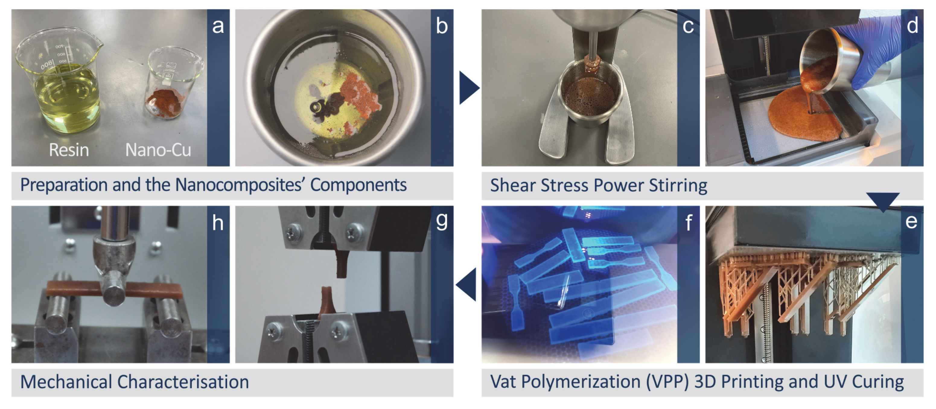
Figure 1. The steps of the methodology followed in the work are (a) raw materials, (b) mixing of the raw materials in the weight-to-weight concentration, (c) shear stress power stirring, (d) placing the mixture in the vat photopolymerization 3D printer, (e) 3D printing of the specimens for mechanical testing, (f) UV curing of the specimens, (g) tensile testing, (h) three-point-bending flexural test.
Jfb 13 00258 g001
Figure 2. Cu nanopowder: (a) 5000× SEM image of the Cu nanoparticles, (b) 100,000× SEM image of the Cu nanoparticles, (c) EDS graph on the region shown in (b).
Jfb 13 00258 g002
Figure 3. (a) Weight loss vs. temperature graph, (b) Weight loss rate vs. temperature graph.
Jfb 13 00258 g003
Figure 4. (a) Raman spectra, EDS graphs (b) Biomed amber pure, (c) Biomed amber 0.5 wt.% Cu, (d) Biomed amber 1.0 wt.% Cu. The legend shows which graph corresponds to which material, according to the color of the graph.
Jfb 13 00258 g004
Figure 5. Tensile and flexural stress vs. strain graphs from one randomly selected specimen for each case (a) tensile test of biomed amber pure 3D printed at 0 degree angle, (b) tensile test of biomed amber 0.5 wt.% Cu, 3D printed at 45 degree angle, (c) tensile test of biomed amber 1.0 wt.% Cu, 3D printed at 90 degree angle, (d) flexural test of biomed amber pure 3D printed at 0 degree angle, (e) flexural test of biomed amber 0.5 wt.% Cu, 3D printed at 45 degree angle, (f) flexural test of biomed amber 1.0 wt.% Cu, 3D printed at 90 degree angle.
Jfb 13 00258 g005
Figure 6. Stereoscope images at 0.8× magnification (1) Biomed amber pure, 0 degree 3D printing angle, (2) Biomed amber pure, 45 degree 3D printing angle, (3) Biomed amber pure, 90 degree 3D printing angle, (4) Biomed amber 0.5 wt.% Cu, 0 degree 3D printing angle, (5) Biomed amber 0.5 wt.% Cu, 45 degree 3D printing angle, (6) Biomed amber 0.5 wt.% Cu, 90 degree 3D printing angle, (7) Biomed amber 1.0 wt.% Cu, 0 degree 3D printing angle, (8) Biomed amber 1.0 wt.% Cu, 45 degree 3D printing angle, (9) Biomed amber 1.0 wt.% Cu, 90 degree 3D printing angle.
Jfb 13 00258 g006
Figure 7. SEM images for samples 3D printed with 45 degree angles. Side surface at 30× magnification (1) Biomed amber pure, (2) Biomed amber 0.5 wt.% Cu, (3) Biomed amber 1.0 wt.% Cu, Fracture surface at 30× magnification (4) Biomed amber pure, (5) Biomed amber 0.5 wt.% Cu, (6) Biomed amber 1.0 wt.% Cu, Fracture surface at 300× magnification (7) Biomed amber pure, (8) Biomed amber 0.5 wt.% Cu, (9) Biomed amber 1.0 wt.% Cu. The arrows show the beginning of the fracture and how it evolved.
Jfb 13 00258 g007
Figure 8. SEM images at 45,000× magnification on the fracture surface of tensile test samples made with the nanocomposites prepared in the work (a) Biomed amber 0.5 wt.% Cu, (b) Biomed amber 1.0 wt.% Cu, (c) EDS graph acquired on the region indicated in (b).
Jfb 13 00258 g008
Figure 9. Main effects plots vs. control parameters (Cu concentration and printing angle) (a) surface roughness and area measurements’ location, (b) cross-section area (mm2/%), (c) surface roughness Ra (μm) horizontal and vertical measurements, (d) surface roughness Rz (μm) horizontal and vertical measurements.
Jfb 13 00258 g009
Figure 10. Main effects plots vs. control parameters (Cu concentration and printing angle) (a) tensile strength (MPa), (b) tensile modulus of elasticity (GPa), (c) tensile toughness (MJ/m3), (d) flexural strength (MPa), (e) flexural modulus of elasticity (GPa), (f) flexural toughness (MJ/m3).
Jfb 13 00258 g010
Figure 11. Interaction plots vs. control parameters (Cu concentration and printing angle) (a) cross-section area to nominal (%), (b) cross-section area (mm2), (c) surface roughness Ra (μm) horizontal, (d) surface roughness Ra (μm) vertical, (e) surface roughness Rz (μm) horizontal, (f) surface roughness Rz (μm) vertical.
Jfb 13 00258 g011
Figure 12. Interaction plots vs. control parameters (Cu concentration and printing angle) (a) tensile strength (MPa), (b) tensile modulus of elasticity (GPa), (c) tensile toughness (MJ/m3), (d) flexural strength (MPa), (e) flexural modulus of elasticity (GPa), (f) flexural toughness (MJ/m3).
Jfb 13 00258 g012
Figure 13. Surface graphs vs. control parameters (Cu concentration and printing angle) (a) cross-section area to nominal (%), (b) cross-section area (mm2), (c) surface roughness Ra (μm) horizontal, (d) surface roughness Ra (μm) vertical, (e) surface roughness Rz (μm) horizontal, (f) surface roughness Rz (μm) vertical.
Jfb 13 00258 g013
Figure 14. Surface graphs vs. control parameters (Cu concentration and printing angle) (a) tensile strength (MPa), (b) tensile modulus of elasticity (GPa), (c) tensile toughness (MJ/m3), (d) flexural strength (MPa), (e) flexural modulus of elasticity (GPa), (f) flexural toughness (MJ/m3).
Jfb 13 00258 g014
Figure 15. (a) S. aureus, (b) inhibition zone of the biomed amber 0.5 wt.% Cu developed in the S. aureus culture, (c) inhibition zone of the biomed amber 1.0 wt.% Cu developed in the S. aureus culture, (d) E. coli, (e) inhibition zone of the biomed amber 0.5 wt.% Cu developed in the E. coli culture, (f) inhibition zone of the biomed amber 1.0 wt.% Cu developed in the E. coli culture, (g) inspection on the microscope of the specimen in the Petri dish with the E. coli culture, (h) higher magnification microscope image of the biomed amber 0.5 wt.% Cu sample, (i) higher magnification microscope image of the biomed amber 1.0 wt.% Cu sample, (j) pure biomed amber used as a control against S. aureus, (k) pure biomed amber used as a control against E. coli.
Jfb 13 00258 g015
Table 1. Nanocomposite elements.
#Filler Consideration wt.% CuResin
10.0Biomed Amber
20.5Biomed Amber
31.0Biomed Amber
Table 2. Full factorial design: control parameters and levels.
RunFiller Consideration wt.% CuPrinting Angle/PA (deg.)
10.00
20.045
30.090
40.50
50.545
60.590
71.00
81.045
91.090
Table 3. Major Raman peaks identified and their related assignments.
Wavenumber (cm−1)Raman Peak Assignment
756O-C(O)-O stretching [109]
778Si-O stretching [110], O-C(O)-O stretching [111]
820phenyl ring vibration [111,112]
878ν[O−(C=O)−O], ν(C−CH3), r(CH3), ν(ring) [109,111,113]
938C-H bending [109,111]
1200C-O-C stretching [109]
1243C-O-C symmetric stretch [109]
1294C-O-C symmetric stretch [109,111] or CH2 [112]
1364C–C-H, C-O–H, and O-C-H [114]
1449CH3 bending [109,111,113]
1638v (C=C) [115]
1723ν (C=O) [115]
2935CH2 asymmetric stretching [114]
2953CH2 asymmetric stretching [114]
Table 4. Increased Raman peaks in samples with Cu particles and their related assignments.
Wavenumber (cm−1)Raman Peak AssignmentChange
756O-C(O)-O stretchingStrong increase
778Si-O stretchingStrong increase
820phenyl ring vibrationStrong increase
878ν[O−(C=O)−O], ν(C−CH3), r(CH3), ν(ring)Strong increase
938C-H bendingSmall increase
967Antisymmetric stretching of Si-O A new and strong peak
1122νs(C−C)T A new and small peak
1200smallSmall increase
1243smallSmall increase
Table 5. Mean Average Values and Standard Deviations of measured Tensile Specimen Area, Tensile Specimen Area to Nominal Area, Horizontal and Vertical Ra, and Rz Roughness for each experimental run.
RunCross Section Area (mm2)Area to Nom [%]Ra-Hor. (μm)Rz-Hor. (μm)Ra-Ver. (μm)Rz-Ver. (μm)
110.25 ± 0.05100.73 ± 0.451.27 ± 0.078.46 ± 0.621.77 ± 0.3212.88 ± 2.76
29.89 ± 0.1097.19 ± 0.951.49 ± 0.049.82 ± 0.392.04 ± 0.1812.50 ± 1.14
39.84 ± 0.0396.70 ± 0.281.16 ± 0.218.00 ± 0.881.86 ± 0.0811.42 ± 0.19
49.87 ± 0.1196.95 ± 1.1210.56 ± 0.5952.20 ± 14.654.88 ± 0.8228.20 ± 2.17
59.32 ± 0.0891.59 ± 0.755.42 ± 0.3930.60 ± 3.585.28 ± 0.9225.40 ± 6.77
69.34 ± 0.0891.78 ± 0.802.92 ± 0.3619.20 ± 1.305.30 ± 1.0927.40 ± 3.71
79.48 ± 0.0993.19 ± 0.915.34 ± 0.4232.00 ± 12.517.24 ± 0.8133.00 ± 3.67
89.22 ± 0.0390.64 ± 0.342.98 ± 0.5818.80 ± 2.684.72 ± 0.7329.20 ± 5.02
99.31 ± 0.0491.48 ± 0.391.43 ± 0.209.74 ± 2.022.72 ± 0.5915.20 ± 4.76
Table 6. Mean Average Values and Standard Deviations of measured Responses for Tensile Strength, Tensile Modulus of Elasticity, Tensile Toughness, Flexural Strength, Flexural Modulus of Elasticity, and Flexural Toughness for each experimental run.
RunsB Tension (MPa)E Tension (MPa)Toughness Tension (MJ/m3)sB Flexural (MPa)E Flexural (MPa)Toughness Flexural (MJ/m3)
171.91 ± 1.03222.04 ± 20.7720.73 ± 2.5797.86 ± 0.592275.98 ± 22.192.68 ± 0.02
273.68 ± 0.58310.31 ± 11.0313.87 ± 0.98104.49 ± 2.332616.88 ± 80.582.97 ± 0.08
371.49 ± 1.47319.12 ± 14.9710.97 ± 2.13108.06 ± 1.792746.75 ± 63.123.10 ± 0.06
478.63 ± 1.96320.85 ± 16.0614.97 ± 1.24109.42 ± 1.522573.82 ± 38.043.05 ± 0.04
580.96 ± 0.74345.99 ± 12.1015.53 ± 1.40113.49 ± 2.482811.18 ± 68.653.26 ± 0.07
682.53 ± 0.24350.18 ± 10.4416.69 ± 1.11115.37 ± 2.632911.61 ± 75.713.40 ± 0.09
778.20 ± 1.14297.76 ± 14.0415.84 ± 0.30101.27 ± 0.802350.87 ± 24.042.81 ± 0.03
875.53 ± 2.73330.86 ± 7.9815.56 ± 6.19109.33 ± 2.512710.62 ± 60.433.14 ± 0.06
980.04 ± 0.58343.17 ± 2.5314.97 ± 1.78114.03 ± 1.112892.06 ± 73.773.30 ± 0.06
Table 7. Antibacterial test results.
Nano Compound wt.% CuS. aureus IZ (mm)E. coli IZ (mm)
0.00.00.0
0.52.0~0.5
1.07.0~0.5
Publisher’s Note: MDPI stays neutral with regard to jurisdictional claims in published maps and institutional affiliations.