Abstract
The magnetic field distribution along the radius and height in the working chamber of a hydrocyclone with a radial magnetic field is studied. One of the most important parameters of magnetic hydrocyclones is the magnetic field distribution along the radius and height of the working chamber. It is necessary for calculating the coagulation forces and the magnetic force affecting the particle or flocculus. The magnetic field strength was calculated through magnetic induction, measured by a teslameter at equal intervals and at different values of the supply DC current. The obtained values for the magnetic field strength are presented in the form of graphs. The field distribution curves produced from the dependences found earlier were constructed. The correlation coefficients were calculated. It was proven that the analyzed dependences could be used in further calculations of coagulation forces and magnetic force, because theoretical and experimental data compared favourably with each other. The distribution along the radius and height in the cylindrical part of the magnetic hydrocyclone was consistent with data published in the scientific literature.
1. Introduction
Magnetic hydrocyclones are effective in use when fast cleaning of large amounts of lubricating and cleaning fluids is required. However, the scope is not limited to this case. Magnetic hydrocyclones can be successfully used to extract ferromagnetic particles from the waste process liquid, to obtain iron powders and enrich iron ores, etc. [1]. Recently, in order to increase the efficiency of trapping mechanical impurities, superposition of electric fields is used [2]. A magnetic hydrocyclone is one of such devices. There are various designs of these devices, the classification of which is shown in Figure 1.
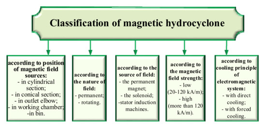
Figure 1.
Classification of magnetic hydrocyclones.
Electromagnetic hydrocyclones with a superposed magnetic field in the cylindrical part of the body are the most widely used, i.e., with a radial magnetic field, known as the Fricker hydrocyclone (Figure 2a) and with an external magnetic field, known as the Watson hydrocyclone (Figure 2b). One of the most important parameters of devices used for cleaning viscous media from magnetic impurities is the distribution of the magnetic field in the working chamber. To calculate the coagulation forces and the magnetic force acting on a particle or floccula, it is necessary to know the magnetic field strength at each point of the working chamber [3]. In the Fricker hydrocyclone, a stator of a DC motor is used as a source of a magnetic field, if it is required to create a continuous magnetic field, or a stator of an asynchronous motor, if it is required to create a rotating magnetic field [4].
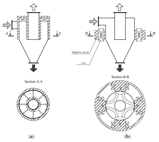
Figure 2.
The Fricker hydrocyclone (a) and the Watson hydrocyclone (b).
For the purpose of this paper, the distribution of an inhomogeneous magnetic field in the cylindrical part of a magnetic Fricker hydrocyclone will be analyzed. The complexity of the assessment lies in the fact that the field strength varies both in the radius of the apparatus and in height. The objective is to verify experimentally the dependencies obtained previously.
2. Materials and Methods
To verify the accuracy of the compiled dependence, the magnetic field was measured in experimental samples of magnetic hydrocyclones. The magnetic field strength was assessed through magnetic induction, measured by a teslameter at equal intervals and at different values of the supply DC. Magnetic field was measured using an EM4305 teslameter (TU U 33.2-00226098-022-2001) at the walls of the magnetic circuit in the plane with the magnetic circuit at the outer the walls of the apparatus.
Issues related to the distribution of the magnetic field in an electromagnetic hydrocyclone have been considered by many scientists [1,2,3,5,6,7]. The work by J. Chen shows the experimental data on the change in the magnetic field strength along the radius [8]. However, they lack analytical expressions for determining the field strength in a hydrocyclone. In addition, his work shows graphs of changes in field strength in the working chamber only along the radius, while the field also changes with the height of the apparatus. The work by V. I. Prosvirnin gives a more complete picture of the distribution of the magnetic field by experimental measurement of the magnetic field in the cylindrical part of the hydrocyclone by the radius and height of the apparatus (Figure 2) [9]. The article [2] gives an analytical expression of the criteria for evaluating magnetic hydrocyclones based on the assessment of the magnetic field in the working field [10].
3. Results
V. I. Prosvirnin proposed the following formula for changing the magnetic field strength of the Fricker hydrocyclone:
where H0 is the value of the magnetic field in the output (maximum intensity), A/M; R0 is the radius of the outlet, m; R is the radius at which the field strength value is to be calculated, m.
As a source of information on the change in the magnetic field strength along the radius, the data by J. Chen [11,12,13,14] were used. When comparing the data obtained empirically with Formula (1), it can be seen that for small values of tension, they are in good agreement with each other (Figure 3a). However, with a significant increase in the current in the coil (Figure 3b), the relative error between the experimental and theoretical readings can be up to 90%. Thus, to apply the Formula (1) is unacceptable for significant values of the magnetic field strength.
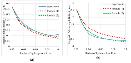
Figure 3.
The change in magnetic field strength along the radius at various currents in the winding: (a) I = 1 A; (b) I = 8 A.
Formula (1) can be upgraded so that it takes into account the above disadvantage:
where N is the empirical coefficient, which can be found from the following relation:
where H1 is the intensity of the magnetic field in the point with the radius R1, A/M.
For the most accurate results, H1 should be measured at the wall of the cylindrical portion of the hydrocyclone. Despite the fact that the calculation of devices for separating magnetic particles from viscous and fluid media has been studied by many authors, we believe that it is necessary to experimentally find the magnetic field strength at the nodal points.
Formula (1) is a special case of the Formula (2) with n = 1.
As the expression H(R), either (2) and (3) or the other empirical formula may be used:
where H1 is the magnetic field strength at the wall of the cylindrical part of the hydrocyclone; R1 is the radius of the cylindrical part of the hydrocyclone; n1 is the coefficient taking into account the curvature of the graph.
The analogy of Formula (4) with the transition process of the inertial link of the first order is obvious. Based on this, we can safely say that the value of R1/n1 is an analogy of the time constant T and the coefficient n1 = 3 ÷ 5, because transient time lasts 3 ÷ 5T. Obviously, the greater is the curvature of the distribution of the magnetic field along the radius, the greater is the value of the coefficient n1.
The boundary conditions are as follows:
- with R = R0: H(R) = H0;
- with R = R1: , as n1 takes on a value more than 3, i.e., and the second term can be neglected due to its smallness, therefore H(R) = H1.
The results of applying Formula (4) are given in Figure 4.
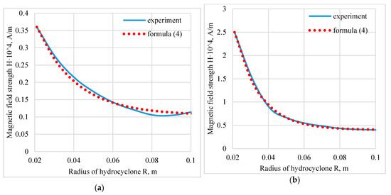
Figure 4.
Change in magnetic field strength along the radius at various currents in the winding: (a) I = 1 A, n1 = 4; (b) I = 8 A, n1 = 5.7.
As an expression H(Z) the authors use the formula compiled by analogy with the previous:
where H2 is the magnetic field strength at the bottom of the hydrocyclone; Z1 is the height of the cylindrical part of the hydrocyclone; n2 is the coefficient taking into account the curvature of the graph.
Z1 is selected approximately 1/3 of the distance between the source of the magnetic field and the end of the magnetic circuit. As a source of information on the change in the magnetic field intensity with height, we use the data by V. I. Prosvirnin [10]. Graphs showing the data obtained with the Formula (6) and the experimental data are shown in Figure 5.
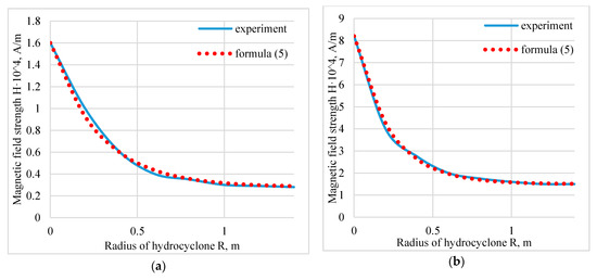
Figure 5.
Change in magnetic field strength in height at various currents in the winding: (a) I = 10 A, n1 = 5; (b) I = 40 A, n1 = 6.
The authors propose the following model of a change in the magnetic field in the chamber along the radius and the height of the hydrocyclone:
where H0-H3 are the magnetic field strengths which are measured at the specified points (Figure 6).
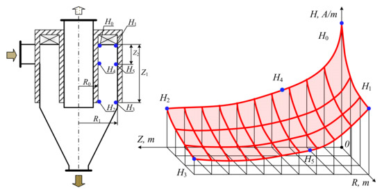
Figure 6.
The changes in the magnetic field strength in the hydrocyclone working chamber.
>> R1 = [0.021, 0.031, 0.041, 0.051, 0.061, 0.071, 0.081, 0.091, 0.101];
>> Exp1 = [2.5, 1.5, 0.86, 0.65, 0.54, 0.48, 0.43, 0.41, 0.4];
>> For1 = Exp1(1)*(R1(1)./R1);
>> For2 = Exp1(1)*(R1(1)./R1).^1.35;
>> plot(R1, Exp1, ’b-’);
>> hold on;
>> plot(R1, For1, ’r--’);
>> plot(R1, For2, ’m:’);
>> hold off;
>> grid;
>> title(’The change in magnetic field strength along the radius at various currents in the winding: (a) I = 1 A; (b) I = 8 A’);
>> xlabel(’Radius of hydrocyclone R, m’);
>> ylabel(’Magnetic field strength H*10^4, A/m’);
>> text(R1(9), Exp1(9),’\leftarrow experiment’);
>> text(R1(9), For1(9),’\leftarrow Formula (1)’);
>> text(R1(9), For2(9),’\leftarrow Formula (2)’);
For the coefficient n to be determined in a more accurate way, its arithmetic mean of n1 and n2 may be taken. To do this, one should take the value of the magnetic field at points H4 and H5, located at a distance of 1/3 of the total height of the magnetic circuit, as it is most likely that one will find the true value of the coefficients at this height:
The results of modeling with H0 = 2.5 × 10⁴ A/M, H1 = 1 × 10⁴ A/M, H2 = 0.5 × 10⁴ A/M, H3 = 0.3 × 10⁴ A/M, n = 5 are given in Figure 7.
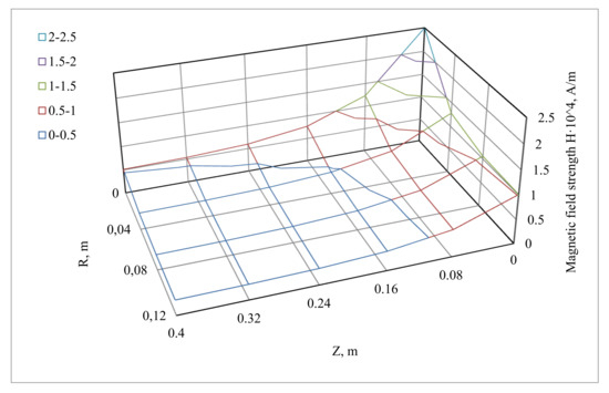
Figure 7.
The change in the magnetic field strength in the working chamber of the hydrocyclone, calculated by the Formula (6).
The model for changing the magnetic field strength in the working chamber along the radius and height of the hydrocyclone can be simplified using the Formula (2).
The simplified formula will be as follows:
To verify the dependencies in the laboratory, an electromagnetic hydrocyclone was tested. The magnetic field in the separation zone was measured with a teslameter F 4354/1 in various sections along the radius and height of the cylindrical part. Figure 8 shows the dependences of the magnetic field strength H on the height of the cyclone h measured on the outer surface of the outlet pipe (Figure 8a) and on the inner surface of the cyclone body (Figure 8b). The field is constant in absolute value along the greater part of the cyclone height hц (0.4–1.6 m) − 1.6 m). It reaches 1.8 × 10⁴ A/m (up to 200 E). Therefore, it is sufficient for the coagulation of ferromagnetic particles.
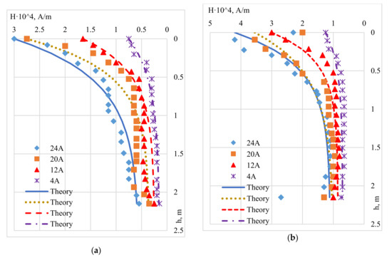
Figure 8.
The distribution of the magnetic field in an electromagnetic hydrocyclone on the outer surface of the outlet pipe (a) and the inner surface of the hydrocyclone body (b) at different currents.
The data obtained experimentally were verified with theoretical studies based on Formula (9). The maximum and minimum field values were taken as the initial and final values of the field strength (without taking into account the small curvature of the field in the lower part and inaccuracies in the measurements). The correlation coefficient between experiment and theory is presented in Table 1.

Table 1.
The coefficient of correlation between the experiments and the theory.
As it can be seen from Table 1, Formula (9) may be used with the high accuracy.
4. Discussion
The study presents mathematical models that display the change in the magnetic field in the Fricker hydrocyclone working chamber. Experimental research of the distribution of magnetic field strength in the hydrocyclone working chamber with a radial magnetic field in radius and height was conducted. The data obtained were compared with theoretical ones. In most cases, the correlation coefficient between the experiment and the theory was not less than 0.95, i.e., a high degree of similarity. The empirically produced data coincide with the previously given dependence of the field changes in the cylindrical part of the apparatus, required for calculating coagulation forces and magnetic force.
Author Contributions
Conceptualization, B.A.; methodology, B.A.; software, R.D.; validation, R.D.; formal analysis, S.C.; investigation, B.A.; resources, B.A.; data curation, B.A.; writing—original draft preparation, B.A.; writing—review and editing, R.D.; visualization, R.D.; supervision, B.A. All authors have read and agreed to the published version of the manuscript.
Funding
This research was funded by grant of the State Council of Crimea to young scientists of the Republic of Crimea.
Conflicts of Interest
The authors declare no conflict of interest.
References
- Chen, G. Design and Analysis of Magnetic Hydrocyclone; McGill University: Montreal, QC, Canada, 1989. [Google Scholar]
- Avdeyev, B. Development of criteria for a magnetic hydrocyclones. In Proceedings of the MATEC Web Conference International Conference on Modern Trends in Manufacturing Technologies and Equipment (ICMTMTE 2017), Kerch, Russia, 11–15 September 2017; Kerch State Maritime Technological University: Kerch, Russia, 2017; Volume 129, p. 06012. [Google Scholar] [CrossRef][Green Version]
- Avdeyev, B.; Masyutkin, E.; Golikov, S.; Sokolov, S.; Gavrilov, V. Calculation of efficiency curve of magnetic hydrocyclone. In Proceedings of the 2017 IEEE Conference of Russian Young Researchers in Electrical and Electronic Engineering (EIConRus), St. Petersburg, Russia, 1–3 February 2017; 2017; pp. 1225–1228. [Google Scholar] [CrossRef]
- Avdeyev, B.; Prosvirnin, V.; Dema, R. Calculation of magnetic devices cleaning coolants in the agro–industrial complex. In Proceedings of the MATEC Web of Conferences, “International Conference on Modern Trends in Manufacturing Technologies and Equipment (ICMTMTE 2018)”, Sevastopol, Russia, 10–14 September 2018; Volume 224, p. 05003. [Google Scholar] [CrossRef]
- Zhukov, V.; Masyutkin, E.; Avdeyev, B. The application of mathematical modeling for the development of devices as an example of viscous fluid purification from magnetic impurity. In Proceedings of the IOP Conference Series: Materials Science and Engineering, Tomsk, Russia, 27–29 October 2016; IOP Publishing Ltd.: Bristol, UK, 2017; Volume 177, p. 012015. [Google Scholar] [CrossRef]
- Sokolova, E.A.; Aslanov, G.A.; Sokolov, A.A. Modern approach to storing 3d geometry of objects in machine engineering industry. In Proceedings of the IOP Conference Series: Materials Science and Engineering, Tomsk, Russia, 27–29 October 2016; p. 177(012036). [Google Scholar]
- Dema, R.R.; Amirov, R.N.; Kalugina, O.B. Determining the parameters effecting the work of the lubricants supplying system at wide-strip hot rolling. In Lecture Notes in Mechanical Engineering; Springer International Publishing: Cham, Switzerland, 2019; pp. 929–937. [Google Scholar]
- Sokolov, S.; Zhilenkov, A.; Chernyi, S.; Nyrkov, A.; Glebov, N. Hybrid neural networks in cyber physical system interface control systems. Bull. Electr. Eng. Inf. 2020, 9. [Google Scholar] [CrossRef]
- Premaratne, W.A.P.J.; Rowson, N.A. Development of a Magnetic Hydro-cyclone Separation for the Recovery of Titanium from Beach Sands. Phys. Sep. Sci. Eng. 2003, 12, 215–222. [Google Scholar] [CrossRef]
- Donskoi, E.; Suthers, S.P.; Campbell, J.J.; Raynlyn, T. Modelling and optimization of hydrocyclone for iron ore fines beneficiation-using optical image analysis and iron ore texture classification. Int. J. Miner. Process 2008, 87, 106–119. [Google Scholar] [CrossRef]
- Ali-Zade, P.; Ustun, O.; Vardarli, F.; Sobolev, K. Development of an electromagnetic hydrocyclone separator forpurification of wastewater. Water Environ. J. 2008, 22, 11–16. [Google Scholar] [CrossRef]
- Sokolov, S.; Zhilenkov, A.; Chernyi, S.; Nyrkov, A.; Mamunts, D. Dynamics Models of Synchronized Piecewise Linear Discrete Chaotic Systems of High Order. Symmetry 2019, 11, 236. [Google Scholar] [CrossRef]
- Chernyi, S. Techniques for selecting topology and implementing the distributed control system network for maritime platforms. AKCE Int. J. Graphs Comb. 2018, 15, 219–223. [Google Scholar] [CrossRef]
- Zhilenkov, A.; Chernyi, S.; Sokolov, S.; Nyrkov, A. Intelligent autonomous navigation system for UAV in randomly changing environmental conditions. J. Intell. Fuzzy Syst. 2020, 1–7. [Google Scholar] [CrossRef]
© 2020 by the authors. Licensee MDPI, Basel, Switzerland. This article is an open access article distributed under the terms and conditions of the Creative Commons Attribution (CC BY) license (http://creativecommons.org/licenses/by/4.0/).