Article

Gap Size Dependence of Atomistic-Resolved Peptide Bond Signals by Tunneling Current Across Nano-Gaps of Graphene Nano-Ribbons

Dipartimento di Scienze di Base e Applicate per l’Ingegneria, University of Rome “La Sapienza”, Via A. Scarpa 14–16, 00161 Rome, Italy
*
Author to whom correspondence should be addressed.
Computation 2020, 8(2), 29; https://doi.org/10.3390/computation8020029
Submission received: 17 March 2020 / Revised: 2 April 2020 / Accepted: 3 April 2020 / Published: 14 April 2020
(This article belongs to the Section Computational Chemistry)

Abstract

:
According to the recent literature, it has been demonstrated that the atomistic scale recognition of amino acids and peptide-bonds in polypeptides and proteins is in principle possible by measuring the tunneling current flowing across a narrow nano-gap in graphene nano ribbons during the peptide translocation. In this paper, we concentrate on the tunneling current signal properties measured for nano-gaps of different sizes. Using the non equilibrium Green function method based on the density functional theory, we have studied the tunneling current for larger gap sizes that can be actually realized according to the present state of the art sub-nanometer nano-pore and nano-gap technology. Also in these cases the peptide bond can be still recognized, the obtained signal being well within the measurable range of the current. The signal shapes undergo a change from a double peak feature per peptide bond for narrow gaps to a structured single peak signal per peptide bond for wider gaps. The reason is related to the different orbital overlap range of the two contributions giving rise to the original double peak signal for narrow gaps.

1. Introduction

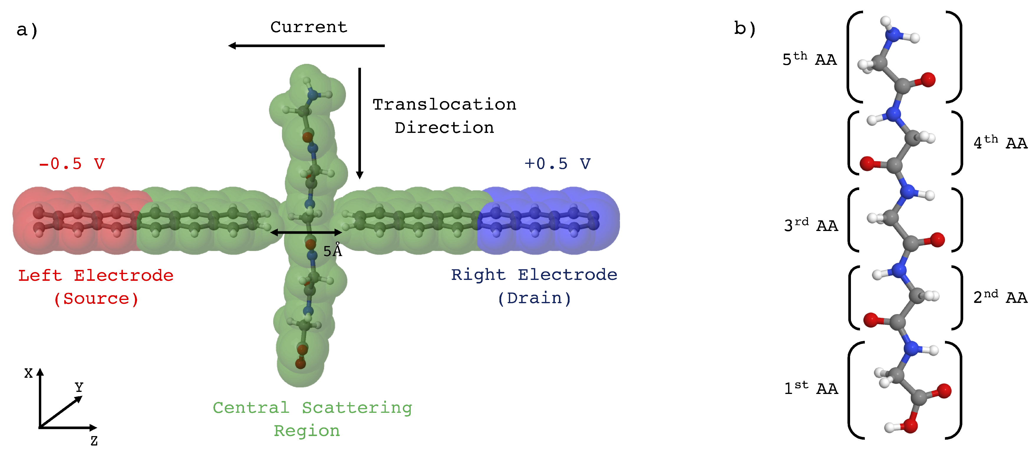
The importance of identifying the sequence and the 3-D structure of proteins is crucial to understand their function and behavior within living organisms; for instance, mis-folding of proteins is believed to be related to neurodegenerative diseases such as Parkinson’s and Alzheimer. Current methods require long sequencing times that represent a serious bottleneck for the needs of the rising importance of proteomics. Then, fast and efficient techniques (especially for large protein chains) are required and solid-state nanopores and nanogaps are emerging as promising tools for single molecule analysis [1,2,3]. In this framework, a new sequencer consisting of arrays of nano-gaps between graphene nano-ribbons has recently been proposed [4], as schematically represented in Figure 1a, exploiting the ideal 2D structure of the leads that allows an atomistic resolution sensing. While the molecule (in this case an amino acids chain) is led to translocate through the gap between the two leads, a tunneling current is induced to flow across the leads where a voltage bias is applied, thus allowing in principle the atomistic recognition of the specific portion of the molecule right in the middle of the gap. The collected signal could be processed and employed to obtain the primary structure of a peptide or a protein. A Density Functional Theory (DFT) based ab initio study, in conjunction with the Non Equilibrium Green Function (NEGF) method [5,6] and the Landauer-Büttiker approach [7], has evidenced clear peptide bond fingerprints made of two well defined current peaks of the order of magnitude of nA in the case of glycine poly-peptides translocating across a 5 Å wide nano-gap [4]. The same ideal nano-gap device has been considered to study also an-elastic phenomena that are ignored in the DFT-NEGF model: inelastic electcron tunneling spectra have revealed that that phonon assisted tunneling events and non linear I-V characteristics are important issues and that the non-linear features related to these phenomena allow the identification of peptide bond and amino-acids side chains as well [8]. The most advanced current nano-technological processes have allowed the manufacturing of stable graphene 1 nm wide nanogaps [9] and even sub-nanometer gaps with other materials [10]. However the realization of stable 5 Å nano-gaps, as the ones employed in the previous proof of principles studies on the amino-acid recognition by tunneling current, is still to come. Hence, in order to get closer to nanogap configurations practically achievable on the basis of the present technological capabilities, it is important to try to enlarge the gap size and to investigate further the effect of the gap size on the tunneling current signal. The present work is therefore devoted to study, employing the above mentioned DFT-NEGF approach, the change of the transport properties of the system composed by the peptide and the graphene nanoribbon as the nano-gap size is increased. Therefore, while we have re-calculated with a denser resolution the current signal for a 5 Å nano-gap, we have extended the study of the tunneling current signal for new nano-gaps of 6 Å and 7 Å widths with the same augmented resolution. We have focussed our study on the paradigmatic case of a Gly homo-peptide.

2. Theoretical Method

The ideal device is schematically drawn in Figure 1. Two semi-infinite narrow zig-zag graphene nanorobbons [11] 2-ZGNR are employed as electrodes. It is important to evidence that the electronic ground state of such ribbons is a semi-conducting ferromagnetic state [12,13]; however, the metallic unpolarized configurations is reported to be stable when a bias is applied and in presence of ballistic conduction [14,15]. Moreover it is known that the spin polarized ground state undergoes a transition to semi-metallic conduction properties when the ZGNR is doped with N atoms [16] or when a transverse electric field is applied [17]. Then we have chosen the unpolarized metallic phase of the hydrogenated ZGNR as a paradigmatic case of metallic or half-metallic ideal 2D graphene based electrodes. The metallic behavior of the electrodes employed in the present case is evidenced in Figure 2.
Because the aim of the present article is to study the tunneling current signal by increasing the gap size, we have used three sub-nanometers gaps of respectively 5, 6 and 7 Å.
The gap devices have been fully relaxed in the context of DFT using the Quantum ESPRESSO package [18]: electronic structures are calculated in the framework of a plane-wave basis set expansion, using a plane-wave energy cutoff of 70 Ry and an artificial smearing of 0.005 Ry. PBE (Perdew-Burke-Ernzerhof) [19] functional is used for the electron exchange and correlation potential V x c [ n ( r ) ] and norm-conserving pseudopotetials built with the Troullier-Martins scheme [20] are employed to reduce the number of electrons that are treated explicitly. Self-consistent calculation are performed until the convergence threshold of 0.001 a.u. for the total force was achieved.
The initial stage was aimed to collect the homopeptide configurations during the translocation across the gap. This stage has been performed through non-equilibrium steered classical molecular dynamics (SMD) simulations [21] in water with a total number of atoms N = 27 , 322 . The SMD simulations have been performed at T = 300 K constant temperature using the Berendsen thermostat and a constant velocity steering protocol ( v = 0.001 Å/fs). The Gly homopeptide has been translocated across the gap five times in sequence employing the periodic boundary conditions perpendicularly to the GNR plane. It is important to evidence that we are only dealing with completely linearized zig-zag configuration of the peptide: a larger peptide or protein should be eventually led to translocate across the nano-gap after complete de-naturation and only its primary structure is analyzed.
Then we have selected those configurations having meaningful groups located in the gap and in the GNR plane, namely the carboxyl ( C O ) and the amino ( N H ) groups (that are bonded together in the peptide bond), the side chain ( S C ) and the middle-bond configurations between these three groups; water molecules have been removed [4,22] and structures have been further relaxed at T = 0 K, in the context of the density functional theory (DFT), using the SIESTA package [5]. The necessity of this relaxing stage in the context of DFT arises for two main reasons: the first is that the interaction between the ZGNR leads and the peptide during the classical steered MD is basically incorrect due to absence of the electronic (or band structure) part of the interaction between the atoms that might be important especially for distributed wave functions such as the ones of the pseudo- π ZGNR orbitals; secondly the peptide is a little bit strained at the end of the steered MD step due to the large value of the velocity that, for computational reasons, has been employed: this strain needs to be relaxed. In this stage the threshold for the maximum module of the force acting on the atoms was set to 0.1 eV/Å in order to approach a local energy minimum and keep part of the thermal ionic disorder of the initial configuration; the RMSD measured between the quantum relaxed and the SMD configurations is of the order of RMSD ≈ 3.38 Å (RMSD/atom 2.9 × 10 2 Å). In Figure 3 it can be appreciated the change of the atomic positions after this relaxation stage.
Split-double- ζ basis set augmented with polarization orbitals (DZP) are employed for H, O, C and N atoms, using a mesh cutoff of 250 Ry, PBE (Perdew-Burke-Ernzerhof) [19] functional for the electron exchange-correlation potential and norm-conserving Troullier-Martins pseudopotentials [20]. As mentioned, quantum transport calculations have been performed in the context of DFT-NEGF using the TRANSIESTA code [5,23]; the basis set, the electron exchange and correlation potential functional and pseudopotentials are the same used in the previous structural relaxation step.
According to the DFT-NEGF method, the calculation of the transport properties is obtained starting from a block decomposed Hamiltonian:
H = H L + Σ L V L 0 V L H S V R 0 V R H R + Σ R ,
where H L ( R ) and H S are, respectively, the decoupled Hamiltonians of the left (right) electrode and the scattering region, V L ( R ) represents the interaction of left (right) electrode with the scattering region and Σ L ( R ) is the self-energy of the left (right) lead that describes a complex re-normalization of the electrons energy due to the coupling of the left (right) lead with the semi-infinite electrodes.
For an external bias voltage V applied along the z direction, the current I ( V ) is given by Landauer-Büttiker formula [6]
I ( V ) = 2 e h + d ε T ( ε , V ) × f ( ε μ L ) f ( ε μ R ) ,
where f ( ε ) is the Fermi-Dirac distribution function and μ L ( R ) is the electrochemical potential of the left(right) electrode. T ( ε , V ) is the transmission coefficient that is calculated from the Hamiltonian of Equation (1), with the external bias voltage V included in the interaction terms, and is defined as:
T ( ε ) = Tr G ( ε ) Γ L ( ε ) G ( ε ) Γ R ( ε ) ,
where G ( ε ) = lim η 0 + ( ε + i η H ) 1 is the Green’s function of the system and Γ L ( R ) ( ε ) = i [ Σ L ( R ) ( ε ) Σ L ( R ) ( ε ) ] is the left(right) coupling function [24]. All DFT and quantum transport calculations have been carried out in dry ambient, since the presence of water does not affect the transport properties of the ZGNR nanogap because of the hyrdophobic character of graphene [22]. Moreover, the sizes of the gap considered prevent the passage at the same time of the peptide chain and of water molecules. Although DFT is a ground state theory and not a steady-state one, the DFT-NEGF scheme is the most popular approach for steady-state transport in nanostructures and has been successfully applied in many cases often giving current values close to the ones obtained with other formally correct methods [25,26].

3. Results and Discussion

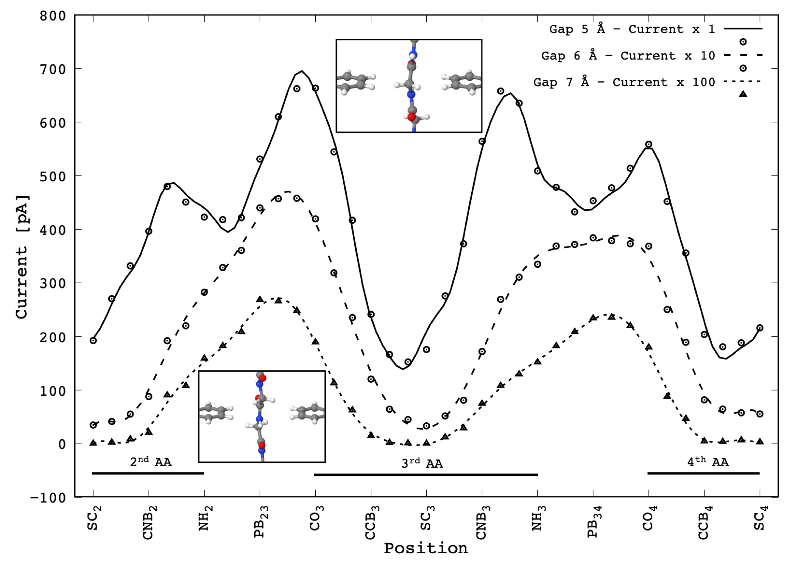
As already mentioned, we have calculated the tunneling current and the transport properties of the system for different gap sizes of 5, 6 and 7 Å. The translocating molecule is a peptide composed by five amino acids but only the central three are taken into account for the present results: indeed the first and the fifth amino acids of the peptide chain are adjacent to the C and the N-terminal groups whose lone pairs could affect the measured current (see Figure 1). The chosen bias between the electrodes is 1 V, that is a common value found in literature in systems concerning tunneling currents or molecular junction [27,28,29]. We have not observed any distortion or problem due to the employed bias, neither for the atomistic structure nor for the electron density and wave-functions. However we are aware that the employed bias could represent a problem in real measurements with ZGNR electrodes due to the large electric field in the gap: enlarging the gap, as we are reporting here, is certainly beneficial for this aspect but further studies are needed, and will be planned, to reduce the bias without affecting too much the level of the current signal. In Figure 4 are reported the current signals calculated for the translocating Gly peptide across the gap with different widths. Each value of the calculated signal have been obtained in quasi-static conditions, that is an idealized quasi-stationary translocation dynamics where the atoms have been relaxed at T = 0 K at each translocation stage as described in Section 2. In the present case we have improved the method employed to obtain the current signal point by point with respect to the recent data published elsewhere [4]: the current values calculated for the positions between two adjacent relaxed configurations were averaged from the ones obtained by a rigid translation of the peptide from the adjacent relaxed configurations.
The reported curves show that the current signal decreases, as expected, by about one order of magnitude with the gap-size increase by 1 Å. Then the maximum current measured decreases from the order of magnitude of ≈1 nA to ≈10 pA. It should be stressed that in any case the current levels predicted are well within the range of measurable currents. The signal measured for the 5 Å gap is in good agreement with that reported elsewhere [4], which was obtained with a coarser sampling grid—the two peaks signal corresponding to each PB during the translocation is basically the same except for the peak height ratio of the second PB which is probably due to the thermal fluctuation during the SMD. We remind that the minima occurring when the Gly side chains (or better the C H 2 group that includes the α -carbon and the hydrogen side chain) are in the middle of the gap ( S C 1 , S C 2 and S C 3 configurations) are fingerprints of the PB being contributed by just the N H groups involved in two adjacent PBs [4].
What is interesting is the change of the signal shape as the gap size is increased—in these cases the two peaks features are lost and just one broad structured peak per PB is evidenced. We remind that the double peak feature found in the 5 Å gap case is due to the coupling of the upper and lower side chains in correspondence with the C O and N H groups in the middle of the gap.
It is important to show that the calculated signal is obtained from a completely de-naturated peptide being characterized by its zig-zag primary structure only and no secondary structure. Therefore the current signal in Figure 4 does not apply in the case of peptides or proteins organized in a secondary structure such as α -helix or β -sheet—in these cases, the situation would be completely different and the atomistic resolution and amino-acid sequencing is unlikely with the present device setup.
For a better comprehension of the current signals observed, the transmission functions of the system for the C N B 3 and P B 34 configurations have been analyzed in the case of the 5 Å and 7 Å wide gaps and are shown in Figure 5. Here both the configurations show the same overall behavior—the contributions to the current are mainly due to the states in the energy range 0.2 e V ε 0.5 e V . This rise corresponds to the energy shift of the pseudo- π HOMO band of the left lead up to the same energy of the right lead pseudo- π * LUMO band [4]. Furthermore, the channel decomposition of the transmission matrix evidences the presence of just one transmission channel for all the configurations here considered with no exception. The disappearance of the characteristic double peak is related to the drop of the C N B 3 transmission function peak in the 7 Å wide gap case causing an inversion of the peak hierarchy with respect to the same configuration in the 5 Å wide gap case. The same, but at a lesser extent, occurs also for the 6 Å wide gap (not reported).
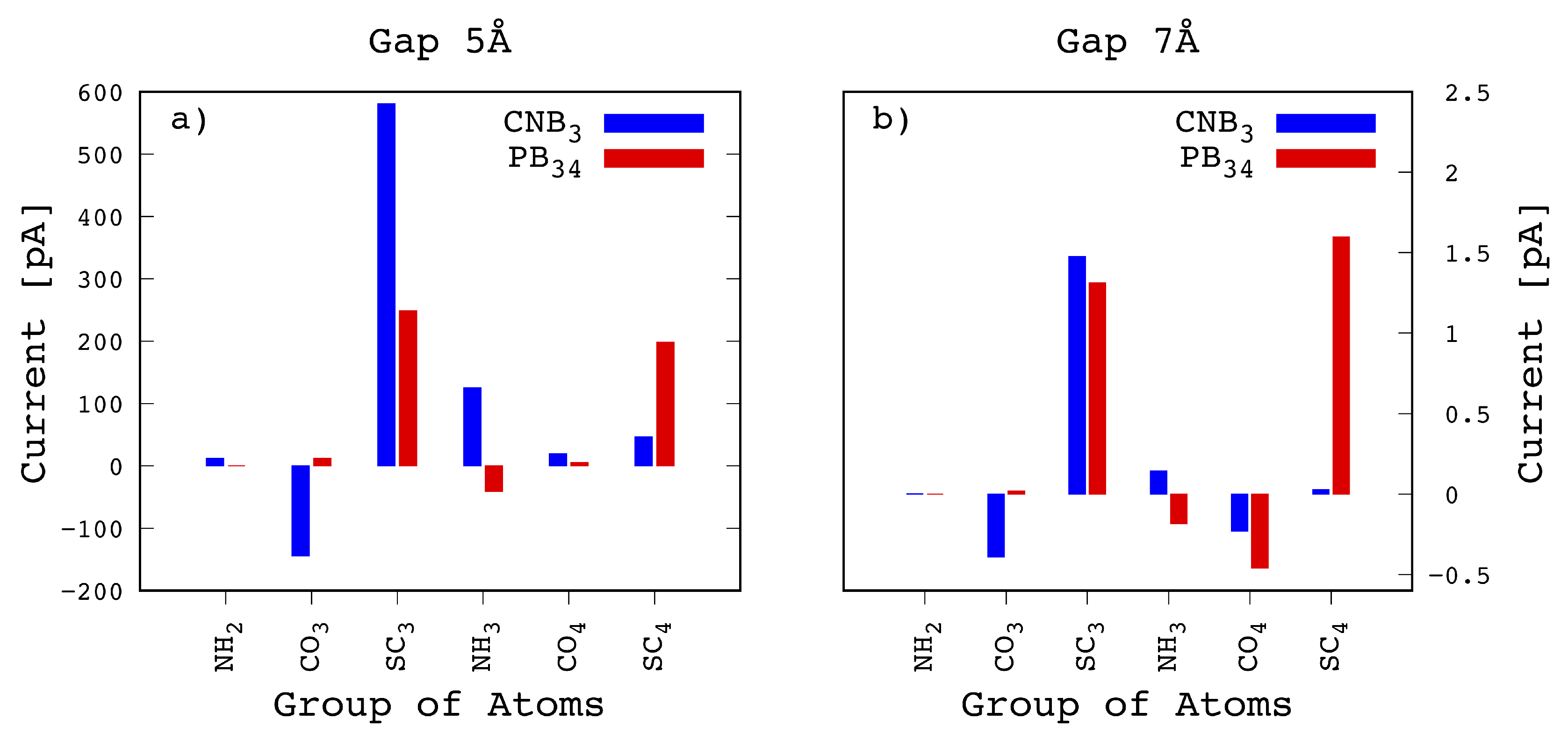
Bond current formulation [30,31,32] gives the access to the knowledge on the atomic sites that play important roles in the transport phenomena. To study the current flows, each section of the peptide chain, and each amino-acid as well, has been ideally decomposed into chemically meaningful atomic groups, namely the C O and the N H groups involved in the PBs, the side chain and the C H chemical group that includes the C- α carbon [4]. In the Gly case, the side chain and C H group are grouped together into the C H 2 group. Then we calculated the current due to the electrons injected from the left lead (that is at a negative bias) into the chemical groups of interest depending on the configuration chosen. The calculated injected local currents, grouped in chemical groups, are reported in Figure 6. Here we have considered the two different configurations already considered in Figure 5, namely C N B 3 and P B 34 , being the ones corresponding to the double peak signal in the 5 Å wide gap device. From Figure 6a it emerges that the main contribution to the first peak comes from from S C 3 with a very intense peak of 580 pA, which is larger than the sum of the two main contributions from the S C 3 and S C 4 (respectively of 248 and 198 pA) calculated for the P B 34 configuration. This is the reason why for the 5 Å gap the tunneling current is characterized by the double peak feature. In Figure 6b the same configurations is reported for the case of the 7 Å wide gap. In this case we see that the S C 3 contribution to the current drops down to similar values as the S C 3 and S C 4 ones for the P B 34 configuration. Moreover we also see that the N H atomic contribution to the transmission, that is minoritary but not negligible in the C N B 3 case for the 5 Å wide gap, is largely reduced for the 7 Å wide gap. As a consequence the double peak feature disappears as already evidenced in Figure 4.
The reasons behind this behavior can be understood by looking at the projected non-equiilibrium density of states. In Figure 7 are reported the non equilibrium density of states projected onto the states belonging to the nearby side chains of the C N B 3 and P B 34 configurations for the 5 Å (Figure 7a) and 7 Å (Figure 7b) gap cases. The right hand piece of the PDOS curves is related to the left spectral density matrix that accounts for the electron injection from the left lead into the central region; as we can see, the PDOS on the S C 3 and S C 4 groups keep the same shape in both the cases whatever the gap size. However concerning the intensity, while for P B 34 we just observe an almost equal intensity reduction for S C 3 and S C 4 with the gap size, in the C N B 3 case the PDOS hierarchy reverses and the S C 3 contribution drops well below the S C 4 one indicating a poor injection from the left lead across S C 3 that was the major contribution for the C N B 3 case in the 5 Å gap. This indicates a poor superposition of the orbitals of S C 3 with the pseudo- π and pseudo- π * GNR orbitals that degrades as soon as the gap size increases.
4. Conclusions

In conclusion, we have studied the gap size dependence of the tunneling current signal obtained during a Gly homopeptide translocation across the two semi-infinite hydrogenated graphene nano ribbons electrodes. The tunneling current signal has been predicted on the basis of DFT-NEGF theory of transport in low dimensional structures. Most importantly it is seen that by increasing the gap size from 5 Å to 7 Å, notwithstanding the current intensity dropping by two orders of magnitude, it still remains well within the measurable range being of the order of tens of pA. This is a key factor for the practical realization of the proposed device and technique because the largest gap size employed is within the present capability of the current state of the art sub-nanometer pore or gap technology. Secondly, we have evidenced that the double peak signal, that characterizes the peptide bond in a 5 Å wide gap, is reduced to a single wide peak signal per peptide bond for the larger 6 and 7 Å gaps. More precisely we observe that the peak related to the P B 34 positions survives while the one corresponding to the C N B 3 configurations drops rapidly and becomes a side satellite of the main peak. The analyses of the local current and the projected non-equilibrium density of states reveals that the range of the orbital superposition involving S C 3 is much shorted for the C N B 3 configuration than for P B 34 one. This behavior is related to different positions of the S C 3 side chain with respect to the ZGNR plane, and to the lobes of the pseudo- π and pseudo- π * GNR orbitals as well, for the two cases. Then the two contributions to the original double peak in the 5 Å gap case are due to orbital overlaps of different ranges.

Author Contributions

T.C. and G.Z. have contributed equally to the work for conceptualization, writing, data curation, analysis, investigation, methodology. Both authors have read and agreed to the published version of the manuscript.

Funding

This research received no external funding.

Acknowledgments

A minor part of the calculations here presented have been run in the CRESCO/ENEAGRID High Performance Computing infrastructure [33]. We acknowledge CRESCO/ENEAGRID the and its staff for this. CRESCO/ENEAGRID High Performance Computing infrastructure is funded by ENEA, the Italian National Agency for New Technologies, Energy and Sustainable Economic Development and by Italian and European research programmes, see http://www.cresco.enea.it/english for~information.

Conflicts of Interest

The authors declare no conflict of interest.

Abbreviations

The following abbreviations are used in this manuscript:
ZGNRZig-zag Graphene Nano-Ribbon
DFTDensity Functional Theory
NEGFNon Equilibrium Green Function
GGAGeneralized Gradient Approximation
PBEPerdew-Burke-Ernzerhof
HOMOHighest Occupied Molecular Orbital
LUMOLowest Unccupied Molecular Orbital
SMDSteered Molecular Dynamics
PBPeptide Bond
PDOSProjected Density Of States

References

  1. Goyal, G.; Lee, Y.B.; Darvish, A.; Ahn, C.W.; Kim, M.J. Hydrophilic and size-controlled graphene nanopores for protein detection. Nanotechnology 2016, 27, 495301. [Google Scholar] [CrossRef] [PubMed] [Green Version]
  2. Sordan, R.; Traversi, F.; Russo, V. Logic gates with a single graphene transistor. Appl. Phys. Lett. 2009, 94, 51. [Google Scholar] [CrossRef] [Green Version]
  3. Prasongkit, J.; Grigoriev, A.; Pathak, B.; Ahuja, R.; Scheicher, R.H. Transverse conductance of DNA nucleotides in a graphene nanogap from first principles. Nano Lett. 2011, 11, 1941–1945. [Google Scholar] [CrossRef] [PubMed] [Green Version]
  4. Rossini, A.E.; Gala, F.; Chinappi, M.; Zollo, G. Peptide bond detection via graphene nanogaps: A proof of principle study. Nanoscale 2018, 10, 5928–5937. [Google Scholar] [CrossRef] [PubMed]
  5. Soler, J.; Artacho, E.; Gale, J.; García, A.; Junquera, J.; Ordejón, P.; Sánchez-Portal, D. The SIESTA method for ab initio order-N materials simulation. J. Phys. Condens. Matter 2002, 14, 2745–2779. [Google Scholar] [CrossRef] [Green Version]
  6. Stokbro, K.; Taylor, J.; Brandbyge, M.; Mozos, J.L.; Ordejón, P. Theoretical study of the nonlinear conductance of Di-thiol benzene coupled to Au(111) surfaces via thiol and thiolate bonds. Comput. Mater. Sci. 2002, 27, 151–160. [Google Scholar] [CrossRef]
  7. Landauer, R. Spatial variation of currents and fields due to localized scatterers in metallic conduction. IBM J. Res. Dev. 1957, 1, 223–231. [Google Scholar] [CrossRef]
  8. Zollo, G.; Rossini, A.E. Vibration assisted electron tunneling through nano-gaps in graphene nano-ribbons for amino-acid and peptide bond recognition. Nanoscale Adv. 2019, 1, 3547–3554. [Google Scholar] [CrossRef]
  9. Heerema, S.J.; Dekker, C. Graphene nanodevices for DNA sequencing. Nat. Nanotechnol. 2016, 11, 127. [Google Scholar] [CrossRef] [Green Version]
  10. Kennedy, E.; Dong, Z.; Tennant, C.; Timp, G. Reading the primary structure of a protein with 0.07 nm3 resolution using a subnanometre-diameter pore. Nat. Nano 2016, 11, 968–976. [Google Scholar] [CrossRef]
  11. Dubois, S.M.; Zanolli, Z.; Declerck, X.; Charlier, J.C. Electronic properties and quantum transport in Graphene-based nanostructures. Eur. Phys. J. B 2009, 72, 1–24. [Google Scholar] [CrossRef]
  12. Son, Y.W.; Cohen, M.L.; Louie, S.G. Energy Gaps in Graphene Nanoribbons. Phys. Rev. Lett. 2006, 97, 216803. [Google Scholar] [CrossRef] [PubMed] [Green Version]
  13. Li, Y.Y.; Chen, M.X.; Weinert, M.; Li, L. Direct experimental determination of onset of electron–electron interactions in gap opening of zigzag graphene nanoribbons. Nat. Commun. 2014, 5, 4311. [Google Scholar] [CrossRef] [PubMed]
  14. Gunlycke, D.; Areshkin, D.A.; Li, J.; Mintmire, J.W.; White, C.T. Graphene Nanostrip Digital Memory Device. Nano Lett. 2007, 7, 3608–3611. [Google Scholar] [CrossRef]
  15. Li, Z.; Qian, H.; Wu, J.; Gu, B.L.; Duan, W. Role of Symmetry in the Transport Properties of Graphene Nanoribbons under Bias. Phys. Rev. Lett. 2008, 100, 206802. [Google Scholar] [CrossRef] [Green Version]
  16. Li, Y.; Zhou, Z.; Shen, P.; Chen, Z. Spin Gapless Semiconductor?Metal?Half-Metal Properties in Nitrogen-Doped Zigzag Graphene Nanoribbons. ACS Nano 2009, 3, 1952–1958. [Google Scholar] [CrossRef]
  17. Son, Y.W.; Cohen, M.L.; Louie, S.G. Half-metallic graphene nanoribbons. Nature 2006, 444, 347–349. [Google Scholar] [CrossRef] [Green Version]
  18. Giannozzi, P.; Baroni, S.; Bonini, N.; Calandra, M.; Car, R.; Cavazzoni, C.; Ceresoli, D.; Chiarotti, G.L.; Cococcioni, M.; Dabo, I.; et al. QUANTUM ESPRESSO: A modular and open-source software project for quantum simulations of materials. J. Phys. Condens. Matter 2009, 21, 395502. [Google Scholar] [CrossRef]
  19. Perdew, J.; Burke, K.; M. Ernzerhof. Generalized Gradient Approximation Made Simple. Phys. Rev. Lett. 1996, 77, 3865–3868. [Google Scholar] [CrossRef] [Green Version]
  20. Troullier, N.; Martins, J. Efficient pseudopotentials for plane-wave calculations. Phys. Rev. B 1991, 43, 1993. [Google Scholar] [CrossRef]
  21. Phillips, J.C.; Braun, R.; Wang, W.; Gumbart, J.; Tajkhorshid, E.; Villa, E.; Chipot, C.; Skeel, R.D.; Kale’, L.; Schulten, K. Scalable Molecular Dynamics with NAMD. J. Comput. Chem. 2005, 26, 1781–1802. [Google Scholar] [CrossRef] [Green Version]
  22. Feliciano, G.; Sanz-Navarro, C.; Coutinho Neto, M.; Ordejón, P.; Scheicher, R.H.; Rocha, A.R. Capacitive DNA Detection Driven by Electronic Charge Fluctuations in a Graphene Nanopore. Phys. Rev. Appl. 2015, 3, 034003. [Google Scholar] [CrossRef]
  23. Stokbro, K.; Taylor, J.; Brandbyge, M.; Ordejón, P. TranSIESTA—A Spice for Molecular Electronics. Ann. N. Y. Acad. Sci. 2003, 1006, 212–226. [Google Scholar] [CrossRef]
  24. Datta, S. Electronic Transport in Mesoscopic Systems; Cambridge Studies in Semiconductor Physics and Microelectronic Engineering; Cambridge University Press: Cambridge, UK, 1995. [Google Scholar]
  25. Liu, S.; Nurbawono, A.; Zhang, C. Density Functional Theory for Steady-State Nonequilibrium Molecular Junctions. Sci. Rep. 2015, 5, 15386. [Google Scholar] [CrossRef] [PubMed] [Green Version]
  26. Yam, C.; Zheng, X.; Chen, G.; Wang, Y.; Frauenheim, T.; Niehaus, T.A. Time-dependent versus static quantum transport simulations beyond linear response. Phys. Rev. B 2011, 83, 245448. [Google Scholar] [CrossRef] [Green Version]
  27. Zhao, Y.; Ashcroft, B.; Zhang, P.; Liu, H.; Sen, S.; Song, W.; Im, J.; Gyarfas, B.; Manna, S.; Biswas, S.; et al. Single-molecule spectroscopy of amino acids and peptides by recognition tunnelling. Nat. Nanotechnol. 2014, 9, 466–473. [Google Scholar] [CrossRef] [PubMed]
  28. McFarland, H.L.; Ahmed, T.; Zhu, J.X.; Balatsky, A.V.; Haraldsen, J.T. First-Principles Investigation of Nanopore Sequencing Using Variable Voltage Bias on Graphene-Based Nanoribbons. J. Phys. Chem. Lett. 2015, 6, 2616–2621. [Google Scholar] [CrossRef] [PubMed] [Green Version]
  29. Reed, M.A.; Zhou, C.; Muller, C.J.; Burgin, T.P.; Tour, J.M. Conductance of a Molecular Junction. Science 1997, 278, 252–254. [Google Scholar] [CrossRef] [Green Version]
  30. Solomon, G.C.; Herrmann, C.; Hansen, T.; Mujica, V.; Ratner, M.A. Exploring local currents in molecular junctions. Nat. Chem. 2010, 2, 223–228. [Google Scholar] [CrossRef]
  31. Todorov, T.N. Tight-binding simulation of current-carrying nanostructures. J. Phys. Condens. Matter 2002, 14, 3049. [Google Scholar] [CrossRef]
  32. Papior, N.; Lorente, N.; Frederiksen, T.; García, A.; Brandbyge, M. Improvements on non-equilibrium and transport Green function techniques: The next-generation transiesta. Comput. Phys. Commun. 2017, 212, 8–24. [Google Scholar] [CrossRef] [Green Version]
  33. Ponti, G.; Palombi, F.; Abate, D.; Ambrosino, F.; Aprea, G.; Bastianelli, T.; Beone, F.; Bertini, R.; Bracco, G.; Caporicci, M.; et al. The role of medium size facilities in the HPC ecosystem: The case of the new CRESCO4 cluster integrated in the ENEAGRID infrastructure. IEEE HPCS 2014, 6903807, 1030–1033. [Google Scholar]
Figure 1. (a) atomistic model of peptide sequencing using a 2-ZGNR nanogap device. The amino acids chain translocates through the gap formed by the two hydrogenated semi-infinite graphene nanoribbons. Provided a bias is applied between the electrodes, a transverse tunneling current flows thus carrying the atomistic resolution information on the piece of the peptide in the gap [4]. The gap size in this scheme is 5 Å but in this study we have considered gap sizes ranging from 5 to 7 Å. (b) All the calculations were conducted on the paradigmatic case of a homopeptide with five glycine residues translocating through the gap. Only the central three amino-acids of the peptide chain have been considered for the present study, the extreme ones being too close to the C and the N-terminal groups whose lone pairs could affect the measured current.
Computation 08 00029 g001
Figure 2. Band structure of the spin unpolarized state of the 2-ZGNR employed as metallic electrodes in the present setup.
Computation 08 00029 g002
Figure 3. Example of a DFT relaxation pattern at the second stage of the protocol described in the text. Here we represent the NH 3 configuration case (see Section 3): (a) initial atomic positions; (b) final atomic positions.
Computation 08 00029 g003
Figure 4. Tunneling current signals flowing across the 2-ZGNR nano-gap devices of different sizes (5 Å, 6 Å, 7 Å) with an applied bias of Δ V = 1 V during the translocation of the Gly penta-peptide through the nano-gap. The labels in the x-axis represent the atomic groups that are located in the middle of the gap during the translocation— C O i , N H i and S C i are the configurations with, respectively, the carbonyl, the amine and the side chain group belonging i-th amino acid right in the center of the nano-gap. Similarly for C N B i and C C B i with reference to the C-N and the C-C middle bonds of the i-th amino acid and for P B i j that indicates the peptide bond between the i-th with the j-th amino acid. Only the three central amino acids are considered (see text). The scale factors of the current signals for the 5, 6 and 7 Å wide gaps are respectively 1, 10 and 100. All the curves have minima with the side-chain located in the middle of the gap ( S C 2 , S C 3 and S C 4 configurations, see text). Note how the characteristic double peak [4] per peptide bond evolves into a broad structured peak, centered at P B 23 and P B 34 , as the gap size is increased.
Computation 08 00029 g004
Figure 5. Transmission functions related to the configurations C N B 3 and P B 34 for two different gap size: 5 Å (a) and 7 Å (b). In both the cases, the states that contributes most to the transport are the ones in the energy range [0.2 eV ϵ 0.5 eV]. The gap size affects the transmission function hierarchy: for the widest gap (b) the transmission function hierarchy of the P B 34 and C N B 3 configurations is opposite to that obtained for the narrowest gap (a).
Computation 08 00029 g005
Figure 6. Bond current decomposition of C N B 3 and P B 34 configurations for two different gap sizes 5 Å (a) and 7 Å (b). For the narrowest gap, the injection into the S C 3 for C N B 3 is very large, being also larger than the sum of the injection into S C 3 and S C 4 for P B 34 . For the widest gap the injection into the S C 3 groups drops for C N B 3 .
Computation 08 00029 g006
Figure 7. Projected Density of States of the system related to the configurations C N B 3 and P B 34 for two different nano-gap sizes: 5 Å (left) and 7 Å (right). In both cases, the most relevant contribution to the transmission is given by S C 3 and S C 4 . However while S C 3 and S C 4 PDOS maintain the same hierarchy for P B 34 at both the gap sizes, in the C N B 3 this circumstance does not occur and there is a change of hierarchy.
Computation 08 00029 g007