
Article

AI-Driven Thermodynamic Evaluation of Beta-Type Stirling Engine Using CFD Simulation and Numerical Calculations


by
Amir H. Shahriari
1,2,
Majid Monajjemi
3,* and
Fatemeh Mollaamin
4
1
Department of Computer Engineering, Central Tehran Campus, Islamic Azad University, Tehran 1496969191, Iran
2
Department of Computing, Macquarie University, Sydney, NSW 2109, Australia
3
Department of Biology, Faculty of Science, Kastamonu University, Kastamonu 37100, Turkey
4
Department of Biomedical Engineering, Faculty of Engineering and Architecture, Kastamonu University, Kastamonu 37150, Turkey
*
Author to whom correspondence should be addressed.
Computation 2026, 14(6), 119; https://doi.org/10.3390/computation14060119
Submission received: 27 April 2026 / Revised: 17 May 2026 / Accepted: 21 May 2026 / Published: 22 May 2026
(This article belongs to the Section Computational Engineering)

Abstract

This study presents an AI-assisted thermodynamic and computational fluid dynamics (CFD) evaluation of a β-type Stirling engine to improve its thermal efficiency and indicated power output. The engine performance was investigated using Restricted Dimensions Thermodynamics (RDT), the Schmidt thermodynamic model, and three-dimensional CFD simulations under various operating and geometric conditions. Key parameters including rotational speed, phase angle, piston diameter, displacer stroke, porosity, and charged pressure were systematically analyzed to determine their influence on engine behavior. A feed-forward artificial neural network (ANN) trained using the Levenberg–Marquardt optimization algorithm was integrated with CFD-generated datasets to predict engine performance and accelerate the optimization process. The AI-assisted optimization was coupled with the Variable Step-size Simplified Conjugate Gradient Method (VSCGM) to identify near-optimal operating conditions while reducing computational cost. Simulation results demonstrated that the optimization process improved the indicated power from 180.33 W to 185.44 W and increased thermal efficiency from 10.32% to 11.54%. The results also showed close agreement between predicted and experimental pressure–temperature profiles, confirming the reliability of the proposed methodology. Furthermore, CFD analyses revealed that increasing piston diameter and optimizing porosity enhanced heat transfer and pressure distribution within the engine chambers, resulting in improved thermodynamic performance. The proposed AI-driven framework provides a reliable and computationally efficient approach for the design and optimization of advanced β-type Stirling engines operating under realistic thermal conditions.

1. Introduction

1.1. Stirling Engine Features

Stirling engines are closed-cycle regenerative heat engines capable of converting thermal energy into mechanical work through cyclic compression and expansion of a working fluid under different temperature levels [1,2,3]. Because the heat source is external, Stirling engines can operate using various energy sources such as solar energy, biomass, geothermal energy, and industrial waste heat [4,5,6]. These engines are recognized for their high thermal efficiency, low noise and vibration, fuel flexibility, and environmentally friendly operation compared with conventional internal combustion engines [7]. Among the three major Stirling engine configurations (α-, β-, and γ-type), the β-type Stirling engine [5] has attracted considerable attention because both the piston and displacer are housed within a single cylinder, reducing mechanical complexity and minimizing sealing problems at high temperatures. In addition, the β-type configuration offers improved thermal reliability and compactness, making it suitable for small-scale power generation and waste heat recovery applications [5]. Subsequent research, including work by Kaushik et al. [8], incorporated mechanical and thermal losses along with finite heat capacities, demonstrating that realistic efficiency predictions require consideration of both heat and work irreversibility. Several studies have investigated the thermodynamic and fluid dynamic behavior of Stirling engines using analytical, numerical, and experimental approaches [8,9,10,11]. Classical thermodynamic models such as the Schmidt model [12] and finite-time thermodynamics have been widely applied to estimate pressure variations, heat transfer characteristics, and thermal efficiency. Recent developments in computational fluid dynamics (CFD) have enabled more accurate simulation of oscillatory flow, pressure distribution, and heat transfer processes within Stirling engine chambers and regenerators. Previous studies demonstrated that engine performance is strongly affected by parameters such as piston diameter, phase angle, rotational speed, porosity, dead volume, and charging pressure. Hou et al. [13] designed a thermo acoustic double-acting Stirling electrical generator for electrical generators and energy recovery systems. The β-type engine incorporates a single cylinder housing both a piston and a displacer [14]. Although many investigations have focused on thermodynamic modeling or CFD simulations independently, limited studies have integrated CFD analysis with artificial intelligence (AI)-based optimization techniques for β-type Stirling engines. Furthermore, previous works rarely addressed the simultaneous optimization of geometric and operating parameters under realistic thermal and flow conditions. Conventional optimization methods generally require large computational effort and extensive iterative simulations, especially when multiple nonlinear parameters interact simultaneously. Recently, artificial intelligence and machine learning methods have emerged as powerful tools for engineering optimization problems involving nonlinear thermodynamic systems. AI models can identify complex relationships between design variables and engine performance while significantly reducing computational time [15,16]. By combining CFD-generated datasets with machine learning algorithms, it becomes possible to predict engine behavior more accurately and accelerate the optimization process. Therefore, the present study proposes an integrated AI-assisted CFD and thermodynamic framework for evaluating and optimizing the performance of a β-type Stirling engine. The Restricted Dimensions Thermodynamics (RDT) model, Schmidt thermodynamic analysis, and three-dimensional CFD simulations are combined with an artificial neural network (ANN) trained using the Levenberg–Marquardt optimization algorithm. In addition, the Variable Step-size Simplified Conjugate Gradient Method (VSCGM) is employed to optimize non-monotonic design parameters including rotational speed, phase angle, piston diameter, displacer stroke, and porosity. AI-based optimization can enhance cylinder placement, flow channel design, and regenerator efficiency, providing a balance between power density and thermal performance (Figure 1 and Table 1). Recent years have witnessed significant progress in the modeling and optimization of Stirling engines through the combined use of thermodynamic analysis, computational fluid dynamics (CFD), and data-driven methods. CFD-based investigations have become increasingly important for resolving complex transient phenomena such as oscillatory compressible flow; conjugate heat transfer, and regenerator losses, which are difficult to capture using simplified thermodynamic models alone. In 2024 a recent comprehensive review by Lain et al. [17], emphasized that modern Stirling engine simulations often require multi-physics coupling, including turbulence modeling, moving mesh techniques, and porous media formulations for regenerators, highlighting the increasing reliance on CFD for realistic engine prediction and design improvement. In parallel, machine learning and artificial intelligence (AI) methods have emerged as powerful tools for accelerating CFD-based design and optimization processes. Recent studies demonstrate that artificial neural networks (ANNs) and hybrid AI frameworks can effectively learn nonlinear relationships between engine parameters and performance outputs, such as power, efficiency, and pressure evolution, significantly reducing the computational cost associated with iterative numerical simulations (Masoumi et al., 2024) [18]. Moreover, broader CFD–ML integration studies show that surrogate modeling and data-driven regression techniques are increasingly being used for inverse design and real-time prediction in complex fluid systems, including thermodynamic cycles (Wang et al., 2024) [19]. For Stirling engine systems specifically, recent research has explored optimization strategies combining evolutionary algorithms and neural networks to improve performance under multi-variable constraints. These approaches confirm that coupling thermodynamic simulation with AI-based optimization can enhance convergence speed and identify near-optimal configurations more efficiently than traditional gradient-based methods (Zhou et al., 2023) [20]. Additionally, systematic reviews indicate a growing research trend toward integrating renewable energy systems with intelligent computational frameworks, particularly for waste heat recovery applications using Stirling engines (Zhang et al., 2023) [21]. Despite these advances, most existing studies either focus on CFD-based thermodynamic analysis or AI-based surrogate modeling independently. Fully integrated frameworks that combine high-fidelity CFD simulations with machine-learning-driven optimization for β-type Stirling engines remain limited. This gap highlights the need for unified hybrid methodologies capable of simultaneously improving prediction accuracy, reducing computational cost, and optimizing both geometric and operational parameters under realistic operating conditions.
The main objectives of this study are summarized as follows: (a) to develop a thermodynamic and CFD-based model for analyzing β-type Stirling engine performance; (b) to investigate the effects of geometric and operating parameters on indicated power and thermal efficiency; (c) to integrate AI-based prediction methods with CFD-generated datasets for rapid performance estimation; (d) to optimize engine design parameters using the VSCGM optimization technique; (e) to improve engine performance while reducing computational cost and simulation time. The proposed methodology provides a data-driven and computationally efficient framework for the design and optimization of advanced Stirling engines and contributes to the development of intelligent thermodynamic systems for sustainable energy applications.

1.2. Thermodynamic Model of Stirling Engine

The Stirling cycle consists of four thermodynamic processes that the working fluid undergoes during operation. First, the gas expands isothermally while absorbing heat from a high-temperature source. It then passes through a regenerator, where it is cooled at nearly constant volume, transferring heat to the regenerator for use in the next cycle. During compression, the gas is compressed isothermally in a space maintained at a constant low temperature, releasing heat to the cold sink. Finally, the gas flows back through the regenerator, absorbing heat previously stored during the cooling process before returning to the expansion space. In this cycle, the working fluid is compressed in the cold region and expanded in the hot region. A fixed mass of gas is alternately heated and expanded, then cooled and compressed, allowing thermal energy to be converted into mechanical work. The greater the temperature difference between the hot and cold reservoirs, the higher the thermal efficiency, with the maximum theoretical efficiency equal to that of a Carnot cycle. The Stirling engine operates as a closed system with a fixed mass of working fluid. Unlike in other piston engines, no gas enters or leaves the system, and no valves are required. Nevertheless, like all heat engines, it completes a cycle consisting of four essential processes: heating, expansion, cooling, and compression. The dynamic system determines the pistons’ movements, from which their displacements can be calculated for the thermodynamic model based on the volumes of expansion relative to pressure variations. Additionally, the pressure fluctuations and mass transfer in each chamber can be estimated using the following equations:
d P i = γ P i ( d V e i T h e i + d V c i T c k i ) V e i T h e i +   V c i T c k i + γ ( V h T h i +   n = 1 n r V h T h i   + V k T k i )
d m e , c i = P i d V e , c i + 1 γ V e , c i d P i R g a s T h e , c k i
d m h , r , k i = V h , r , k i d P i R g a s T h , r , k i
where superscripts and subscripts are expressed as: γ = specific ratio (J/kg·K); i = time step; e = expansion chamber; h = heater; c = compression chamber; k = cooler; n = node number of regenerator; r = regenerator; nr = maximum node number of regenerator; dP = pressure variation (Pa); dV = volume variation (m3). Moreover, the transport parameters of the operating fluid, which has a dynamic viscosity and thermal conductivity, can be modeled versus temperature and pressure according to empirical equations [22]. Since the amounts of transport parameters vary within the operating range of the Stirling engine and are needed for the calculation of heat transfer within the engine, the heat transfer coefficients should be extracted according to the literature [23,24] as well the following equation:
dU + dW = dQ + dH,
where dQ = change in heat transfer (J) dU = change in internal energy (J) dV = volume variation (m3), and dW = change in pressure work (J). The energy equation for operating fluid in each sub-chamber as well as the energy equation for the regenerator can yield the heat transfer between the solid state and working fluid. Consequently, the operating average pressure of the next step for each zone can be estimated using the ideal gas equation of state. For helium as the operating fluid, the engine has a working temperature and pressure above its critical temperature and critical pressure (around 1.5%.), so, with good approximation, we are able to use the ideal gas equation of state instead of the real gas equation in our model.
T e , c i + 1 = m e , c i m e , c i + 1 T e i + 1 c v m e , c i + 1 [ d Q e , c i + d H e , c i 1 2 P e , c i + P e , c i + 1 d V e , c i ]
T h , r , k i + 1 = m h , r , k i m h , r , k i + 1 T h , r , k i + 1 c v m h , r , k i + 1 [ d Q h , r , k i + d H h , r , k i ]
T r m i + 1 = T r m i d Q r m r m c p , r m
P i + 1 = m t o t a l R g a z V e i + 1 T e i + 1 + V h T h i + 1 + n = 1 n r V r T r i + 1 + V k T k i + 1 + V c i + 1 T c i + 1
where T = temperature (K); cv = constant volume specific heat (J/kg·K); m = mass (kg); V = volume (m3); R = gas constant; rm = wire mesh of regenerator; cp = constant pressure specific heat (J/kg·K); supposing pressure losses in the cylinder due to fast expansion and contraction of flow channels, they can be measured using the following equation and the friction coefficient can be obtained according to the information in the literature [25,26].
P e = P + 0.5 P e + 2 P h + P r + P e , h + P h , r
P c = P + 0.5 P c + 2 P k + P r P r , k P k , c
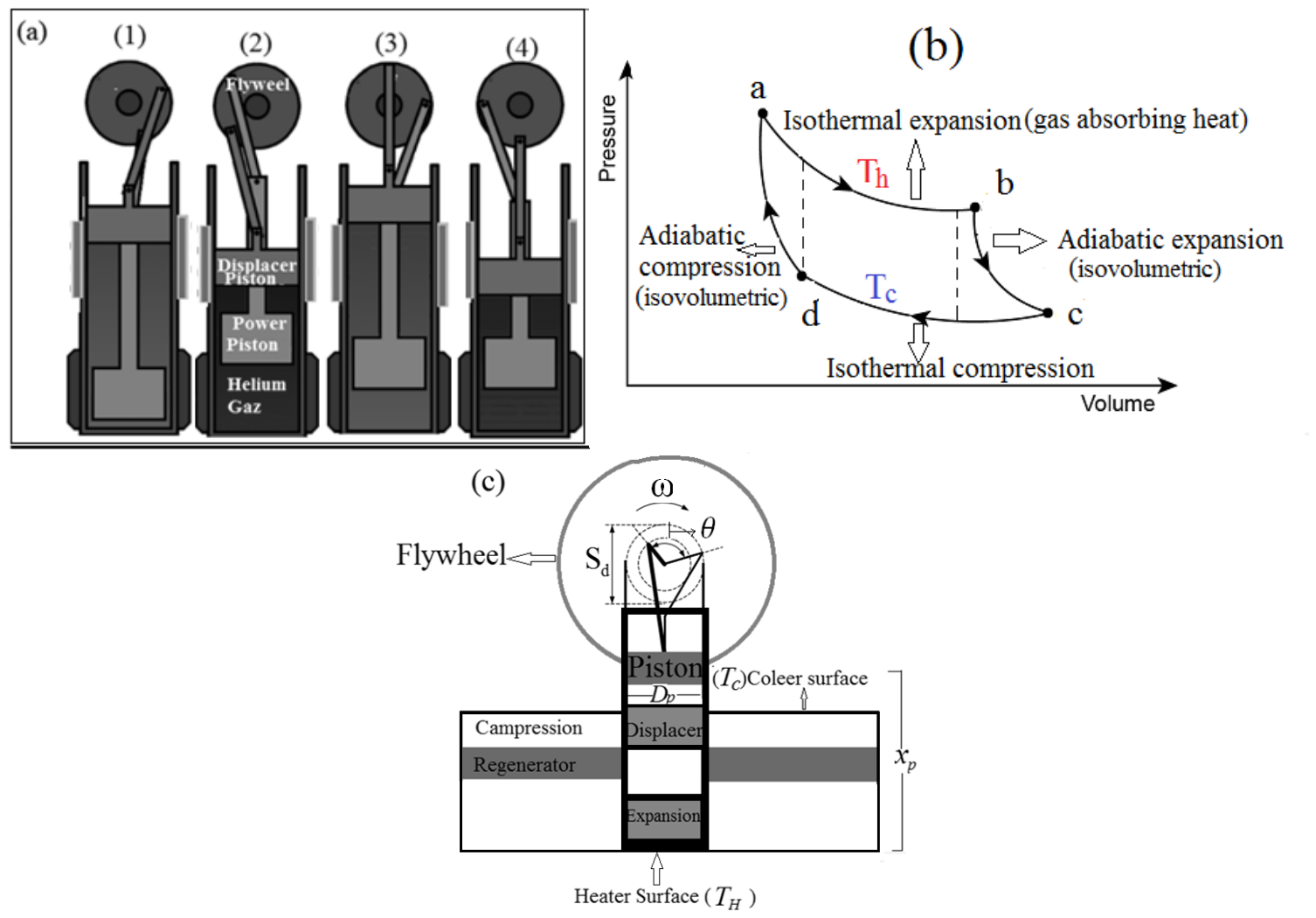
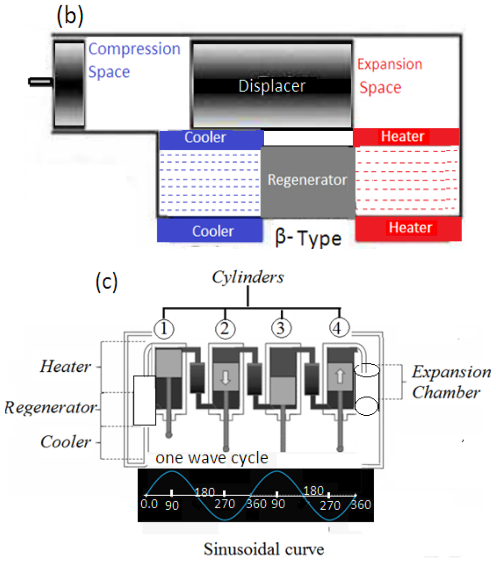
Consequently, according to Equations (9) and (10), through pressures measurements, calculating the forces on each piston’s surface can be easily accomplished through the dynamic approach. The β-type Stirling engine consists of a single cylinder containing both a power piston and a displacer, connected to a common shaft. The power piston is loosely fitted to minimize friction and prevent energy loss from the expanding working fluid. The engine operates by transferring the working gas between the hot and cold regions of the cylinder. When the gas moves toward the hot end, it expands and pushes the piston outward, producing useful work. As the gas shifts to the cold end, it contracts, allowing the piston to return. Unlike the α-type engine, the β-type avoids problems associated with hot moving seals, resulting in improved durability and efficiency (Figure 1). During operation, the displacer is first driven toward the hot side by the flywheel, causing the gas to occupy the cold region and cool. Since the cylinder volume remains nearly constant, the gas pressure decreases. The power piston then compresses the gas as it moves inward while the displacer remains near the cold end. Some of the gas gradually flows back toward the hot end, absorbing heat and increasing the pressure at nearly constant volume. Once the pressure reaches its peak, the gas expands isothermally at the hot end, pushing the piston outward and delivering work to the flywheel. Heat transfer through the cylinder wall ensures that the expansion remains nearly isothermal. As the cycle continues, the gas is displaced toward the cold end, causing the pressure to drop. The piston moves inward while the displacer returns to the cold region, compressing the gas in a nearly isothermal manner and completing the cycle. By integrating the displacer and piston within a single cylinder, the β-type Stirling engine reduces frictional losses and eliminates the need for multiple hot seals. This design promotes smoother thermodynamic cycles, enhances reliability, and is particularly suitable for small-scale or experimental applications. Efficient control of gas movement between the hot and cold ends allows the engine to produce continuous power with minimal energy loss.

2. Materials and Methods

2.1. Methodology

2.1.1. CFD Numerical Procedure, Boundary Conditions, Validation, and Accuracy

The three-dimensional CFD simulations were performed using ANSYS FLUENT v14.5 to investigate the thermo-fluid behavior of the β-type Stirling engine under transient operating conditions. The computational domain included the expansion chamber, compression chamber, regenerator, heat exchanger regions, and moving piston–displacer assembly. A dynamic mesh technique was employed to model the periodic motion of the piston and displacer during engine operation. The governing equations for mass, momentum, and energy conservation were solved using a pressure-based transient solver with second-order discretization schemes to improve numerical accuracy. The working fluid was assumed to be compressible helium behaving as an ideal gas. Turbulence effects were modeled using the realizable k–ε turbulence model because of its robustness and suitability for oscillatory internal flows with moderate Reynolds numbers. Pressure–velocity coupling was achieved using the SIMPLE algorithm. Convergence criteria for continuity, momentum, turbulence, and energy equations were set to 10−5 for all residuals, while the energy residual was reduced below 10−6 to ensure thermal convergence during each time step. The computational mesh consisted of structured, and hybrid hexahedral-dominant cells generated to accurately capture the moving boundaries and heat transfer regions. Mesh refinement was applied near the piston walls, regenerator surfaces, and heat exchanger interfaces where strong thermal and velocity gradients occurred. Three different grid densities were examined to perform the grid independence analysis. The mesh contained approximately 0.42 million cells, the medium mesh contained 0.78 million cells, and the fine mesh contained approximately 1.15 million cells. The difference in predicted indicated power and thermal efficiency between the medium and fine meshes was less than 1.8%, indicating that the medium mesh provided sufficient numerical accuracy with reduced computational cost. Consequently, the medium grid was selected for all subsequent simulations. The expansion chamber wall was maintained at a constant hot-side temperature of 450 K, while the compression chamber wall was fixed at 300 K to represent the cooling condition. The displacer walls were considered adiabatic to minimize additional thermal losses. Moving wall boundary conditions were imposed on the piston and displacer surfaces according to the prescribed sinusoidal motion profiles. Periodic operating conditions were simulated until cyclic steady-state behavior was achieved. The CFD model was validated using experimental data available in the literature for β-type Stirling engines operating under comparable thermal conditions. In particular, the pressure–volume (P–V) diagrams, thermal efficiency, and indicated power predictions were compared with the experimental measurements reported by Dobre et al. and Cheng and Huang. The comparison demonstrated good agreement between numerical and experimental results, with deviations generally below 5% for pressure amplitude and thermal efficiency predictions. Furthermore, the predicted transient pressure profiles at different crankshaft angles closely matched the experimental trends reported in the literature, confirming the reliability and predictive capability of the developed CFD model.

2.1.2. Restricted Dimensions Thermodynamics (RDT) Approach

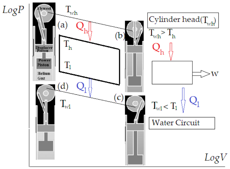
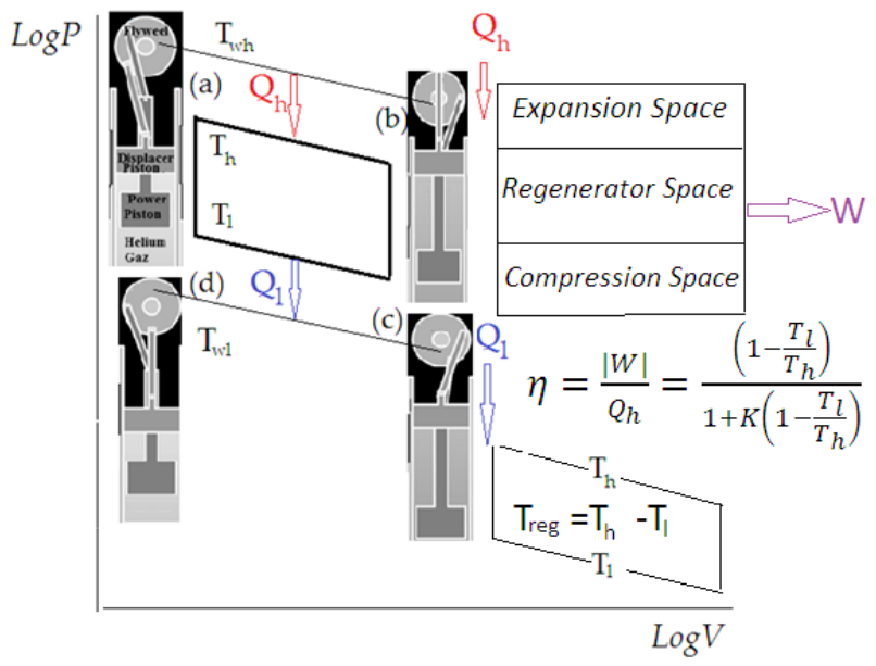
The RDT approach accounts for finite time, geometric sizes, and motion speed in Stirling engines, incorporating internal and external irreversibility [27]. It considers finite heat exchanger contact, limited heat transfer surfaces, mechanical motion constraints, and imperfect regeneration [28]. Engines are characterized by maximum pressure (Pmax), maximum volume (Vmax), heat exchanger properties, and rotational speed, which directly affect heat and mass transfer. Martaj et al. [29] argue that machines following Carnot-like cycles are best characterized using the maximum pressure (Pmax) and maximum volume (Vmax) rather than parameters such as heat exchanger conductance or efficiency. Moreover, rotational speed should be treated as a primary variable, since both heat and mass transfer are directly influenced by it. In the model discussed here, the primary sources of irreversibility are the temperature gradients within the heat exchangers and the inefficiencies in regeneration. The two reservoir wall temperatures are denoted by Twh and Twl. The working fluid absorbs heat Qh,rev at the high temperature Th and releases heat Ql,rev at the low temperature Tl. The network output, W, of the cycle is given by the difference between these heated quantities (see Figure 2).
In an ideal Stirling cycle, from a thermodynamic perspective (Equations (1)–(10)), the amounts of heat exchanged during the isothermal processes in the heat exchangers are as follows:
Q h . r e v   o r   Q a b = P m a x V m a x L n ε ε = E ε
Q h . r e v = Q a b = m R T l L n ε = P m a x V m a x L n ε ε T l T h = E ε T l T h
Here, R and m represent the gas constant and the mass of the working gas, respectively.
The heat is fully transferred from the hot volume to the cold volume and vice versa, neglecting any dead volume. The compression ratio is denoted by ε, while P m a x and V m a x indicate the maximum pressure and maximum volume of the cycle. E ε , represents the reference energy in the RDT model; when the regeneration is perfect, the heat absorbed by the regenerator during the d–a transformation and released during the reversible b–c process is expressed as:
Q r e g e n e r a t o r o r Q r e g = m C v T h T l = m R T h γ 1 1 T l T h = P m a x V m a x ε ( γ 1 ) 1 T l T h
where C v and γ denote the specific heat at constant volume and the adiabatic exponent of the working gas, respectively. With imperfect regeneration ( η r e g < 1 ), additional heat Q p , r e g , must be supplied from the source to the working gas.
Q p , r e g = E ε K 1 T l T h = ( 1 η r e g ) Q T , r e g
K = 1 η r e g L n ε ( γ 1 )
Hence, the total heat Q h supplied to the working gas is the sum of the heat delivered during the isothermal process, Q h . r e v and the additional heat, Q p , r e g required due to imperfect regeneration. Similarly, the total heat Q l rejected from the gas is the sum of the heat released isothermally, Q l . r e v , and the same additional heat, Q p , r e g .
The work per cycle, W, is the algebraic sum of the delivered heat (+) and released heat (−), and it is expressed as follows:
W = Q h   | Q l |   And   η = | W | Q h = 1 T l T h 1 + K 1 T l T h
For the ideal Stirling cycle, the quantities of heat transferred during the isothermal processes in the heat exchangers can be expanded, as shown in Figure 3 and Table 2.
Datasets reported by Dobre et al. [30] and Cheng and Huang [31] were employed for detailed measurements of pressure–volume behavior, thermal efficiency, operating temperatures, and heat transfer characteristics under moderate-temperature operating conditions using helium as the working fluid. These experimental results (Table 2) were used to evaluate the predictive capability of the proposed RDT, Schmidt, CFD, and AI-assisted optimization framework. Furthermore, the pressure–volume (P–V) characteristics obtained from the numerical simulations were compared with the experimental diagrams available in the literature to verify the reliability and consistency of the proposed methodology. The close agreement between numerical predictions and experimental observations confirms the suitability of the developed hybrid CFD–AI model for analyzing and optimizing β-type Stirling engine performance.
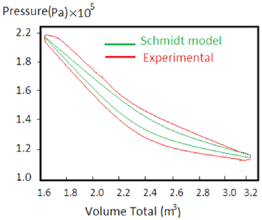
Here, β-type Stirling engine performance was analyzed by assuming the compression spaces are isothermal and the working gas behaves as an ideal gas. Geometric and functional parameters were determined using the “CassyLab” acquisition program, which applies an algorithm based on engine rotational speed, a primary variable in this study. Experimentally, the correlation between the global heat exchange coefficient h and engine speed n was established as h = 4.0079 n1.98, h = 4.0079 [32]. It is notable that the heat transfer coefficient (h) for beta-type Stirling engines varies significantly based on operating speed, gas type, and geometry, typically ranging from roughly 50 to over (W/m2K) on the working fluid side. Key findings indicate impingement is the primary heat transfer mechanism, and the convective coefficient for air is often predicted around 447 (W/m2K). Two thermodynamic models were applied to calculate energy transfer and overall efficiency, while the Schmidt model provided instantaneous variables such as pressure, temperature, volume, and mass, enabling a detailed P-V representation of the cycle. Indicated mechanical work was obtained through numerical integration over the full cycle, and the resulting P-V diagrams were compared with experimental data for the initial conditions summarized in Table 2 and Figure 4.

2.2. Artificial Intelligence (AI) Techniques

The study examined engine performance dependence on rotational speed using two analytical approaches: Restricted Dimensions Thermodynamics (RDT) and the Schmidt model with imperfect regeneration. The RDT method is particularly innovative because it expresses energy exchanges as functions of practical design parameters such as maximum pressure, volume, compression ratio, and source temperatures, which are critical for engineering design. Meanwhile, the Schmidt model tracks the evolution of pressures, volumes, masses, energy exchanges, and irreversibility with respect to crankshaft angle. Key irreversibility arises from imperfect regeneration and temperature differences between the gas and heat exchanger walls. Artificial intelligence (AI) techniques were integrated to optimize parameter estimation and model calibration. Machine learning algorithms analyzed experimental data to refine predictions of heat transfer coefficients and efficiency under varying rotational speeds. This approach enhances model fidelity and allows rapid simulation of multiple operating scenarios, providing engineers with actionable insights during the design stage. Comparison between analytical models and experimental results revealed close agreement, with minor discrepancies attributed to friction and aerodynamic losses not accounted for in the models. Overall, integrating AI with traditional thermodynamic methods offers a promising pathway for enhancing the predictive accuracy and efficiency of Stirling engine design. Table 3 shows the comparison of predicted and experimental pressure and temperature at selected crankshaft angles, demonstrating the predictive accuracy of the AI-assisted Schmidt model.

3. Results

3.1. CFD Model

The current simulation was conducted using ANSYS FLUENT (v14.5) [33], as detailed in the following subsections. The computational model incorporates transport equations for mass, momentum, and energy. Additionally, the turbulent kinetic energy and its dissipation are evaluated, with results compared against the optimal outcomes obtained from the VSCGM optimizer. The governing equations for continuity, momentum, and energy, considering the equation of state ( P = ρ R T   o r   P V = m R T ) , are expressed in
Equations (11), (12), and (13), respectively:
ρ T + . ρ u = 0
ρ u t + . ρ u u = P + . [ μ . u i x j + u j x i + λ . δ i j   . u k x j k ]
ρ E t + . [ ρ E + P u ] = . [ ( λ + c p μ t P r t ) t
where ρ , μ , λ, and δ i j are velocity, density, dynamic viscosity, bulk viscosity coefficient, and Kronecker delta, respectively. According to the Stokes hypothesis, λ can be written as
λ = 3 2   μ
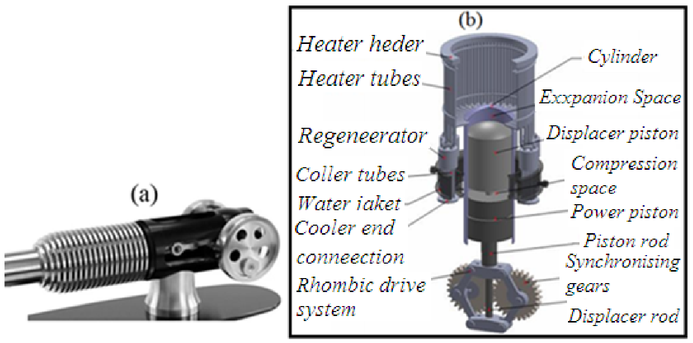
In this study, the flow is treated as oscillatory, viscous, compressible, and Newtonian, following a Cartesian coordinate system (Figure 5a). Flow variables, including velocity, temperature, and pressure, are decomposed into ensemble-averaged quantities denoted as u, T, and p (Figure 5b). Three-dimensional CFD simulations were performed using a numerical module as described in the literature [34]. The engine model, along with its relevant parameters, is illustrated in Figure 5c. The engine domain is divided into three primary regions: the expansion chamber, compression chamber, and regenerator. The expansion chamber interfaces with a high-temperature heat source at the bottom, while the compression chamber is cooled via a heat sink at the top. The regenerator, positioned between the two chambers, recycles heat from the hot working fluid, improving thermal efficiency. Moving components, including the piston and displacer, are connected to a flywheel to facilitate motion. Detailed information regarding the coefficients used in Equations (11)–(13), boundary conditions, and fluid properties is provided in [26]. Key geometric and operating parameters for the baseline engine are listed in Table 4, with additional geometry and operating details according to Figure 5c summarized in Table 5. The baseline engine considered is the KS18 β-type Stirling engine, a 100 W-class device (www.stirlingengine.co.uk), referenced in [35] (Figure 6a). This engine was optimized using the Variable Step-size Simplified Conjugate Gradient Method (VSCGM), illustrated in Figure 6b. The VSCGM is an enhanced version of the traditional SCGM, featuring adaptive step sizes and increments, which reduces the number of iterations required to reach an optimal solution. CFD simulations were employed to validate the optimization results. The β-type Stirling engine analyzed in this study operates as a low-temperature-differential engine, suitable for applications such as waste heat recovery. Typical operating temperatures range from 300 K to 450 K, with some cases reaching up to 600 K [36].
In this study, the performance of a beta-type Stirling engine was investigated using both thermodynamic approaches and computational fluid dynamics (CFD) simulations. The analysis focused on two primary metrics: the indicated power output (W) and thermal efficiency (ε), which were treated as key indicators of engine performance. Stirling engines are typically characterized using pressure–volume (P–V) diagrams, which capture the behavior of the working fluid during the expansion and compression phases. By combining pressure measurements with their corresponding chamber volumes over a full cycle, it is possible to derive an empirical expression for the engine’s indicated power. This relationship can be written as:
W = ω 60 [ P c d V c + P e d V e         &       ε = W Q
Here, ∮ denotes the integral over a complete thermodynamic cycle, Pc and Pe are the pressures in the compression and expansion chambers, respectively, and Q, represents the average heat input per cycle. Thermal efficiency ε is therefore determined by the ratio of indicated power to heat input. Experimental and numerical datasets were generated by simulating the engine under various configurations. Engine parameters were systematically varied, as summarized in Table 4, to obtain a wide range of operational conditions. The resulting data included both the power output and the corresponding thermal efficiency. For neural network training, a total of 100 datasets were compiled, of which 20 representative configurations are listed in Table 5.

3.2. Comprehensive Flowchart of CFD + AI-Enhanced Optimization

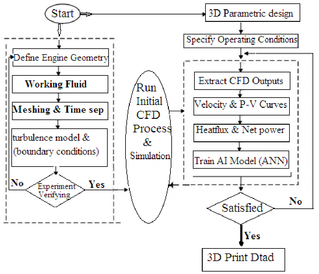
The optimization framework developed in this study integrates computational fluid dynamics (CFD) simulations with artificial intelligence techniques to improve the thermodynamic performance of the beta-type Stirling engine. The proposed methodology combines numerical simulations, data-driven modeling, and iterative optimization in a unified workflow capable of reducing computational cost while maintaining prediction accuracy. Initially, CFD simulations are conducted to evaluate the thermal and fluid dynamic behavior of the engine under different operating conditions. The numerical outputs are subsequently employed to train an artificial intelligence model that can rapidly estimate engine performance for newly generated design conditions. This hybrid CFD–AI strategy enables efficient exploration of the design space and supports the identification of improved engine configurations with enhanced power output and thermal efficiency. The overall procedure adopted in the present work is summarized in Figure 7, which presents the comprehensive flowchart of the CFD and AI-enhanced optimization framework.
The optimization process begins with the initialization of the principal engine design variables and operating parameters. These parameters include piston displacement, displacer geometry, regenerator dimensions, hot- and cold-side temperatures, working fluid conditions, engine speed, and pressure characteristics. Appropriate ranges for these variables are selected according to thermodynamic limitations, previously reported Stirling engine studies, and the geometrical constraints of the investigated beta-type configuration. Defining these parameters at the beginning of the workflow ensures that the optimization process remains physically realistic while providing sufficient flexibility for performance enhancement. Following the initialization stage, detailed CFD simulations are performed to determine the baseline thermodynamic and fluid flow behavior of the engine. The CFD model evaluates important performance indicators such as thermal efficiency, pressure variation, cyclic work, heat transfer characteristics, and power output. In addition, the transient flow structures and temperature distributions inside the expansion and compression spaces are examined to better understand the influence of geometric and operational parameters on engine behavior. The CFD results generated during this stage provide reliable high-fidelity data that form the basis of the subsequent artificial intelligence training procedure. After completing the CFD simulations, the obtained numerical results are systematically stored to establish a comprehensive training database. Each dataset entry contains the selected input design parameters together with the corresponding performance metrics predicted by the CFD model. This database represents the relationship between engine geometry, operating conditions, and thermodynamic response. The quality and diversity of the generated dataset are critical because they directly affect the prediction capability of the artificial intelligence model developed later in the workflow. To accelerate the optimization process, an artificial intelligence model is then constructed using the CFD-generated database. In the revised manuscript, the adopted AI approach is explicitly identified as a feed-forward artificial neural network (ANN). The ANN model was selected because of its capability to capture highly nonlinear relationships between input variables and engine performance characteristics. Unlike conventional regression techniques, ANN models can efficiently approximate complex thermodynamic interactions and multidimensional dependencies commonly observed in Stirling engine systems. The feed-forward ANN used in this work was trained using the Levenberg–Marquardt optimization algorithm. This training algorithm was chosen due to its fast convergence behavior and strong numerical stability when handling nonlinear engineering datasets. The Levenberg–Marquardt method combines the advantages of the gradient descent approach and the Gauss–Newton optimization technique, allowing the network to minimize prediction errors effectively during training. As a result, the developed ANN model achieved accurate prediction capability while requiring significantly lower computational time compared with repeated CFD simulations. Additional methodological details concerning the ANN implementation have also been incorporated into the revised manuscript. The network architecture, including the number of hidden layers and neurons, has been clearly specified to improve reproducibility and transparency. Furthermore, the activation functions used within the hidden and output layers are described to demonstrate how nonlinear mapping between design parameters and performance indicators was established. The manuscript additionally explains the normalization procedure applied to the input and output datasets before the training stage to improve training stability and prediction accuracy of the ANN model.

3.3. Levenberg–Marquardt ANN Implementation

The neural network model was implemented using the Levenberg–Marquardt optimization algorithm [37], which requires the input data to be weighted and normalized using corresponding matrices [38,39]. The network consists of multiple layers of interconnected neurons, where the output of each neuron can serve as input to subsequent layers [40]. Each neuron calculates a linear combination of its inputs, adds a bias term, and applies a transfer function (x) to generate its output. Mathematically, this process is described by:
a = f W p + b
where p is the input vector containing normalized engine parameters, W is the matrix of connection weights, b is the bias vector, and a is the neuron output. The input vector p consists of the following parameters, all extracted from Table 5.
P = [ Ω P c h θ d p x p S d φ T H T C ] × W 1,1 . . . . . . . W 9,1   . W 2,2 . . . . . . . . . W 3,3 . . . . . . . . . W 4,4 . . . . . . . . . W 5,5 . . . . . . . . . W 6,6 . . . . . . . . . W 7,7 . . . . . . . . . W 8,8 . W 1,9 . . . . . . . W 9,9 + [ b 1 b 2 b 3 b 4 b 5 b 6 b 7 b 8 b 9 ] = [ a 1 a 2 a 3 a 4 a 5 a 6 a 7 a 8 a 9 ]  
Here Ω is the rotational speed, Pch the charge pressure, θ the phase angle, dp the piston diameter, xp the equilibrium piston position, Sd the displacer stroke, ϕ the working gas porosity, and TH and TC are the heating and cooling temperatures, respectively. The neural network outputs are the predicted engine performance parameters [ a = w ε ] .

4. Discussion

Using the matrix formulation of inputs, weights, biases, and outputs, the network efficiently maps engine operating conditions to performance metrics. This approach ensures that the model can generalize beyond the training data, providing accurate estimates of both power output and thermal efficiency across a wide range of operating scenarios. Consequently, the methodology presented here offers a robust framework for predicting Stirling engine performance and optimizing design parameters using CFD-generated datasets in combination with neural network modeling. The weight matrix “w” represents the strength of connections between the input layer and the output layer (or the next hidden layer): each w i , j defines the weight connecting the j th input parameter to the ith neuron in the layer. The bias vector b introduces an adjustable offset for each neuron: the network outputs, corresponding to engine performance, are written as:
A   =   [ a 1 a 2 a 3 a 4 a 5 a 6 a 7 a 8 ]   =   f   ( WP   +   b )
where f(x) is the activation function applied elementwise. Specifically, a1 and a2 correspond to predicted power output (w) and thermal efficiency ε , respectively.
The remaining outputs may correspond to internal states or intermediate predictions, depending on the network design. The full network computation can therefore be compactly written as:
a 1 a 2 a 9 = f W 1 , 1 W 1 , 2 W 1 , 9 W 2 , 1 W 2 , 2 W 2 , 9 W 9 , 1 W 9 , 2 W 9 , 9 Ω P c h θ d p x p S d ϕ T H T C + b 1 b 2 b 9
The presented matrices act as direct solution providers, supplying numerical data regarding thermal efficiency and indicated power output of a beta Stirling engine. In the second iteration of the optimization process, the objective function is defined, and the design parameters are updated using the Variable Step-size Conjugate Gradient Method (VSCGM). Iterations continue until the objective function reaches a minimum, indicating an optimal configuration. The objective function is formulated based on two critical performance metrics: the indicated power output and thermal efficiency. Among the nine design parameters considered, some exhibit a monotonic relationship with engine performance. For instance, increasing the charged pressure or the heating temperature consistently enhances both indicated power and thermal efficiency. These parameters can therefore be categorized into two distinct groups: monotonically related variables (such as charged pressure and heating temperature) and non-monotonically related variables (including rotation speed, phase angle, piston diameter, displacer stroke, and porosity) (Table 6).
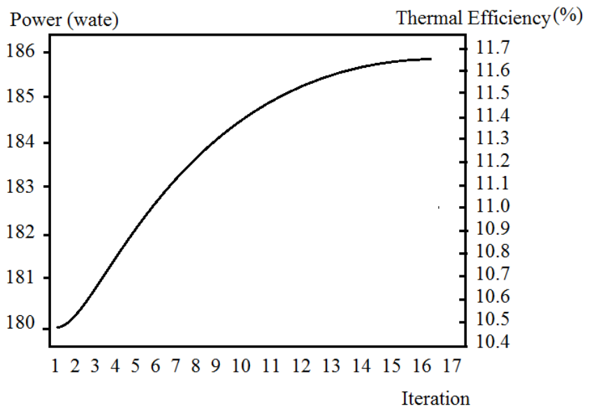
Non-monotonic parameters are particularly significant for simulation studies, as optimizing these variables often yields more precise and actionable results. The results indicate that the optimization process can enhance power output from 180.33 W to 185.44 W, (Figure 8) while thermal efficiency increases from 10.32% to 11.54% (Figure 8). These improvements demonstrate that the optimization process provides valuable insights for engine designers, facilitating data-driven decisions that maximize performance. Figure 7 and Figure 8 from the simulation illustrate the optimization dynamics. For instance, the baseline case completes 20 iterations, during which the objective function steadily declines, while indicated power and thermal efficiency increase.
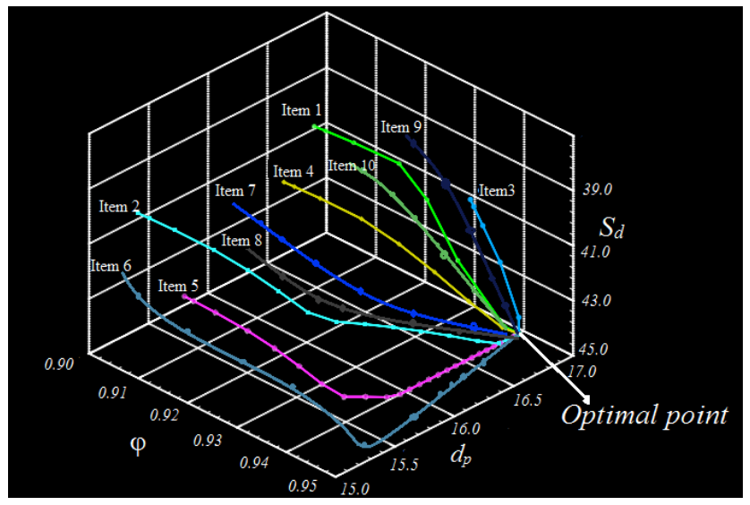
Additionally, multiple trajectories from spatially scattered initial points converge to a single optimal point in the design variable space, confirming the robustness and reliability of the VSCGM-based optimization. Computational fluid dynamics (CFD) simulations integrated with the VSCGM optimizer enable detailed analysis of P–V curves.
According to Figure 9 as well as the CFD simulation results summarized in Table 5, the significant influence of geometric and operating parameters on the thermodynamic performance of the β-type Stirling engine can be demonstrated. Variations in rotational speed, charged pressure, piston diameter, displacer stroke, phase angle, and porosity directly affected both the indicated power output and thermal efficiency. In general, increasing the charged pressure and piston diameter improved engine performance because larger working fluid mass and expanded swept volume enhanced pressure development during the expansion process. For example, increasing the piston diameter from 15 cm to 17 cm increased the indicated power from approximately 180 W to over 220 W under similar operating conditions. Similarly, moderate increases in charged pressure contributed to higher pressure amplitudes inside the expansion chamber, resulting in improved work output. The results also indicate that porosity plays an important role in heat transfer and regenerator effectiveness. Lower porosity values improved thermal efficiency by increasing the heat exchange interaction between the working fluid and the regenerator matrix. However, excessive reduction in porosity may increase flow resistance and pressure losses, which can negatively affect engine operation. The influence of rotational speed was found to be nonlinear. At moderate rotational speeds, improved convective heat transfer enhanced engine performance was recorded, whereas excessively high speeds reduced the available heat transfer time within the cycle, limiting thermal efficiency. Similar behavior has been reported in previous experimental and CFD studies of β-type Stirling engines available in the literature. The phase angle between the piston and displacer also strongly affected pressure evolution and cyclic work production. Configurations operating near 90° phase angle generally produced better thermal performance because they provided more favorable synchronization between compression and expansion processes. Furthermore, variations in displacer stroke modified the gas transfer rate between hot and cold regions, influencing pressure distribution and temperature uniformity within the engine chambers. Overall, the results presented in Table 5 confirm that engine performance depends on the coupled interaction between thermal, geometric, and flow parameters. The CFD-generated datasets provide valuable information for AI-assisted optimization and demonstrate that proper adjustment of non-monotonic parameters can significantly improve both thermal efficiency and indicated power. These findings are consistent with previously published thermodynamic and experimental investigations of β-type Stirling engines and support the reliability of the proposed hybrid CFD–AI methodology.
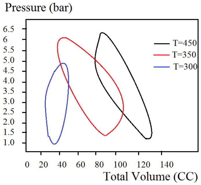
By calculating the area under these curves, the engine’s efficiency can be compared with the ideal Carnot efficiency (Figure 10). Optimization leads to a significant expansion of the P–V diagram area due to gradual increases in piston diameter, which shifts the compression chamber area to the right. This change not only increases swept volume and compression ratio but also enhances pressure during expansion, raising the Reynolds number and improving heat transfer. Consequently, the working gas temperature approaches the wall temperature, contributing to a monotonic increase in thermal efficiency. The indicated power of the engine is derived from the P–V diagram using the relation:
P(piston) = ω/2π∮PdA
where A is the enclosed area of the curve. For these simulations, only nine parameters were varied, periodic boundary conditions were applied, the displacer walls were treated as adiabatic, and piston walls were maintained at 300 K. Iterations were continued until the average cyclic gas temperature reached approximately 450 K, ensuring accurate thermal performance predictions.
Combining AI-based optimization with experimental and simulation data significantly improves the precision of Stirling engine design, allowing engineers to make informed decisions efficiently. This approach demonstrates the potential of data-driven methodologies in advancing thermodynamic system performance.
Table 7 directly links AI predictions with the simulation process, showing a clear path for using AI in engineering optimization. It also highlights how AI can reduce computational cost while maintaining accuracy. The “AI-predicted optimized value” is derived from a trained AI model combining historical simulation data and parametric trends. “Simulated optimized value” represents the result from the actual VSCGM iterative optimization. The close agreement between AI predictions and simulation results shows how AI can accelerate design optimization by suggesting near-optimal starting points, reducing the number of iterations needed. Improvement (%) is calculated relative to the initial design in terms of thermal efficiency and indicated power. In an ideal β-type Stirling cycle, the thermodynamic behavior of the working gas is analyzed assuming the compression spaces are isothermal and the gas behaves ideally. During the isothermal processes, the heat exchanged can be expressed according to Equations (11)–(16). The optimization results presented in Table 7 demonstrate the effectiveness of the AI-assisted optimization framework in predicting near-optimal operating conditions for the β-type Stirling engine. A close agreement is observed between the AI-predicted optimized values and the final simulated optimization results obtained using the Variable Step-size Simplified Conjugate Gradient Method (VSCGM). The small differences between predicted and simulated values confirm the capability of artificial neural network (ANN) model to accurately capture the nonlinear relationships between engine parameters and thermodynamic performance. Among the investigated parameters, rotational speed exhibited a significant influence on both indicated power and thermal efficiency. The AI model predicted an optimal rotational speed of approximately 1615 rpm, while the numerical optimization converged to 1620 rpm, resulting in an indicated power of about 185 W and thermal efficiency near 11.5%. This behavior indicates that moderate increases in rotational speed improve convective heat transfer and pressure development inside the expansion chamber. However, excessively high rotational speeds may reduce the available time for heat exchange, limiting further efficiency improvements. The optimization of phase angle also showed a strong effect on cyclic pressure evolution and piston–displacer synchronization. The AI-assisted model predicted an optimal phase angle close to 91°, which is highly consistent with the simulated optimum of 92°. This confirms that phase relationships near 90° provide favorable thermodynamic conditions for efficient compression and expansion processes. The displacer stroke optimization results indicate that moderate increases in stroke length improve gas transport between hot and cold regions, enhancing thermal interaction and pressure stability. In addition, porosity optimization demonstrated that lower porosity values slightly improved thermal efficiency due to enhanced heat transfer effectiveness within the regenerator matrix. Nevertheless, extremely low porosity values may increase pressure losses and flow resistance, highlighting the importance of balancing thermal and fluid dynamic effects during optimization. Overall, the results in Table 7 confirm that the proposed AI-assisted optimization framework can efficiently identify near-optimal design conditions while significantly reducing computational effort. The agreement between AI predictions and CFD/VSCGM simulation results demonstrates the reliability of integrating machine learning techniques with thermodynamic and CFD analyses for advanced Stirling engine optimization.
The total heat supplied (Qh) and rejected (Ql) account for both the isothermal exchange and regenerator inefficiency. The work per cycle is the algebraic difference between delivered and rejected heat. The average total values of thermodynamic and geometric parameters of the β-type Stirling engine, as mentioned by AI, are listed in Table 8.
The average values listed in Table 8 summarize the principal thermodynamic and geometric parameters of the optimized β-type Stirling engine. These parameters were obtained using the integrated AI-assisted thermodynamic and the CFD optimization framework. The results indicate that the selected operating conditions provide stable thermal performance and improved heat transfer characteristics while maintaining acceptable pressure and flow behavior inside the engine chambers.
Based on these averages, AI-assisted optimization of non-monotonic parameters, including rotation speed, piston diameter, displacer stroke, phase angle, and porosity, was integrated with thermodynamic modeling to improve performance. By predicting near-optimal starting points, AI reduced iterations and guided the VSCGM optimizer to maximize indicated power and efficiency.

5. Conclusions

This study demonstrates a comprehensive methodology for optimizing the performance of a β-type Stirling engine by integrating thermodynamic analysis, numerical simulations, and AI-assisted design. The engine’s thermodynamic behavior was examined using idealized models, including the RDT and Schmidt approaches, to quantify heat exchange, work output, and thermal efficiency. The results indicate that, under ideal conditions, the Stirling cycle efficiently converts thermal energy into mechanical work, with the heat transferred during isothermal processes and the effectiveness of regeneration playing critical roles in overall performance. Optimization of non-monotonic design parameters such as rotation speed, piston diameter, displacer stroke, phase angle, and porosity was achieved using the Variable Step-size Conjugate Gradient Method (VSCGM). By integrating AI predictions, the optimization process converged more rapidly, providing near-optimal initial estimates and significantly reducing computational effort. Simulation results demonstrate an increase in indicated power from 180.33 W to 185.44 W and an improvement in thermal efficiency from 10.32% to 11.54%, highlighting the effectiveness of AI-assisted optimization. Thermodynamic analysis confirmed that enhancements in piston diameter and stroke directly influence the compression ratio, expansion pressure, and Reynolds number, resulting in improved heat transfer and closer alignment of the working gas temperature with wall temperatures. Moreover, combining experimental correlations for heat transfer coefficients with CFD-based P–V analyses provided a robust framework for validating simulation outcomes against physical data. Overall, the integration of AI with classical thermodynamic and numerical models offers a powerful approach for accelerating design decisions and enhancing performance. The methodology presented not only improves engine efficiency and power output but also provides a systematic, data-driven framework for future Stirling engine research, allowing designers to make informed decisions in complex multi-variable optimization problems.

Author Contributions

Conceptualization, M.M. and A.H.S.; methodology, M.M.; software, F.M.; validation, M.M., A.H.S. and F.M.; investigation, M.M. and A.H.S.; resources, A.H.S.; data duration, M.M.; writing—original draft preparation, F.M.; writing—review and editing, M.M.; visualization, F.M. and A.H.S.; supervision, M.M.; project administration, M.M. All authors have read and agreed to the published version of the manuscript.

Funding

This research received no external funding.

Data Availability Statement

The original contributions presented in this study are included in the article. Further inquiries can be directed to the corresponding author.

Acknowledgments

The authors thank the department of computer engineering, CT.C Islamic Azad University, Tehran, Iran, and Kastamonu University.

Conflicts of Interest

The authors declare no conflicts of interest.

References

  1. Ulloa, C.; Porteiro, J.; Eguía, P.; Pousada-Carballo, J. Application model for a Stirling engine micro-generation system in caravans in different European locations. Energies 2013, 6, 717–732. [Google Scholar] [CrossRef] [Scilit]
  2. Costa, S.C.; Tutar, M.; Barreno, I.; Esnaola, J.A.; Barrutia, H.; García, D.; González, M.A.; Prieto, J.I. Experimental and numerical flow investigation of Stirling engine regenerator. Energy 2014, 72, 800–812. [Google Scholar] [CrossRef] [Scilit]
  3. Aksoy, F.; Karabulut, H.; Çınar, C.; Solmaz, H.; Özgören, Y.Ö.; Uyumaz, A. Thermal performance of a Stirling engine powered by a solar simulator. Appl. Therm. Eng. 2015, 86, 161–167. [Google Scholar] [CrossRef] [Scilit]
  4. Ferreira, A.C.; Silva, J.; Teixeira, S.; Teixeira, J.C.; Nebra, S.A. Assessment of the Stirling engine performance comparing two renewable energy sources: Solar energy and biomass. Renew. Energy 2020, 154, 581–597. [Google Scholar] [CrossRef] [Scilit]
  5. Cheng, C.H.; Yang, H.S.; Keong, L. Theoretical and experimental study of a 300-W beta-type Stirling engine. Energy 2013, 59, 590–599. [Google Scholar] [CrossRef] [Scilit]
  6. Sánchez, D.; Chacartegui, R.; Torres, M.; Sánchez, T. Stirling based fuel cell hybrid systems: An alternative for molten carbonate fuel cells. J. Power Sources 2009, 192, 84–93. [Google Scholar] [CrossRef] [Scilit]
  7. Li, Z.; Haramura, Y.; Kato, Y.; Tang, D. Analysis of a high performance model Stirling engine with compact porous-sheets heat exchangers. Energy 2014, 64, 31–43. [Google Scholar] [CrossRef] [Scilit]
  8. Kaushik, S.C.; Kumar, S. Finite time thermodynamic evaluation of irreversible Ericsson and Stirling heat engines. Energy Convers. Manag. 2001, 42, 295–312. [Google Scholar] [CrossRef] [Scilit]
  9. Andresen, B. Finite-time thermodynamics and thermodynamic length. Rev. Gen. Therm. 1996, 35, 647–650. [Google Scholar] [CrossRef] [Scilit]
  10. Senft, J.R. Theoretical limits on the performance of Stirling engines. Int. J. Energy Res. 1998, 22, 991–1000. [Google Scholar] [CrossRef]
  11. De Vos, A. Efficiency of some heat engines at maximum-power conditions. Am. J. Phys. 1985, 53, 570–573. [Google Scholar] [CrossRef] [Scilit]
  12. Donzis, D.A.; Aditya, K.; Sreenivasan, K.R.; Yeung, P.K. The Turbulent Schmidt Number. J. Fluids Eng. 2014, 136, 060912. [Google Scholar] [CrossRef] [Scilit]
  13. Hou, M.; Wu, Z.; Yu, G.; Hu, J.; Luo, E. A thermoacoustic Stirling electrical generator for cold exergy recovery of liquefied nature gas. Appl. Energy 2018, 226, 389–396. [Google Scholar] [CrossRef] [Scilit]
  14. Féniès, G.; Formosa, F.; Ramousse, J.; Badel, A. Double acting Stirling engine: Modeling, experiments and optimization. Appl. Energy 2015, 159, 350–361. [Google Scholar] [CrossRef] [Scilit]
  15. González-Plaza, E.; García, D.; Prieto, J.-I. A Revision of Empirical Models of Stirling Engine Performance Using Simple Artificial Neural Networks. Inventions 2023, 8, 88. [Google Scholar] [CrossRef] [Scilit]
  16. Shahryar Zare, A.R.; Tavakolpour-saleh, A.; Aghahosseini, A.; Sangdani, M.H.; Mirshekari, R. Design and optimization of Stirling engines using soft computing methods: A review. Appl. Energy 2021, 283, 116258. [Google Scholar] [CrossRef] [Scilit]
  17. Laín, S.; Villamil, V.; Vidal, J.R. CFD Simulation of Stirling Engines: A Review. Processes 2024, 12, 2360. [Google Scholar] [CrossRef] [Scilit]
  18. Masoumi, A.P.; Tavakolpour-Saleh, A.R.; Bagherian, V. Performance investigation of an active free-piston Stirling engine using ANN and firefly optimization algorithm. Heliyon 2024, 10, e28387. [Google Scholar] [CrossRef] [Scilit]
  19. Wang, H.; Cao, Y.; Huang, Z.; Liu, Y.; Hu, P.; Luo, X.; Song, Z.; Zhao, W.; Liu, J.; Sun, J.; et al. Recent Advances on Machine Learning for CFD: A Survey. arXiv 2024, arXiv:2408.12171. [Google Scholar] [CrossRef] [Scilit]
  20. Zhou, X.; Xu, X.; Ouyang, X.; Huang, J. Convective meta-thermal concentration for Stirling engine efficiency improvement. arXiv 2023, arXiv:2306.07813. [Google Scholar] [CrossRef] [Scilit]
  21. Zhang, L.; Han, K.; Wang, Y.; Zhu, Y.; Zhong, S.; Zhong, G. A Bibliometric analysis of Stirling engine and in-depth review of its application for energy supply systems. Energy Rev. 2023, 2, 100048. [Google Scholar] [CrossRef] [Scilit]
  22. Kuehl, H.D. Numerically efficient modelling of non-ideal gases and their transport properties in Stirling cycle simulation. In Proceedings of the 17th International Stirling Engine Conference and Exhibition (ISEC), Newcastle upon Tyne, UK, 24–26 August 2016; pp. 572–579. [Google Scholar]
  23. Ackermann, R.A. Cryogenic Regenerative Heat Exchangers; Springer Science & Business Media: Berlin/Heidelberg, Germany, 2013. [Google Scholar]
  24. Rohsenow, W.M.; Hartnett, J.P.; Cho, Y.I. Handbook of Heat Transfer; McGraw-Hill: New York, NY, USA, 1998; Volume 3. [Google Scholar]
  25. Barron, R.F.; Nellis, G.F. Cryogenic Heat Transfer; CRC Press: Boca Raton, FL, USA, 2017. [Google Scholar]
  26. Johnson, R.W. Handbook of Fluid Dynamics; CRC Press: Boca Raton, FL, USA, 2016. [Google Scholar]
  27. Feidt, M. Optimal use of energy systems and processes. Int. J. Exergy 2008, 5, 500–531. [Google Scholar] [CrossRef] [Scilit]
  28. Rochelle, P. LDT Stirling engine simulation and optimization using finite dimension thermodynamics. In Proceedings of the 12th International Stirling Engine Conference, Durham, UK, 7–9 September 2005; pp. 358–366. [Google Scholar]
  29. Martaj, N.; Bennacer, R.; Grosu, L.; Savarese, S.; Laaouatni, A. LTD Stirling engine with regenerator. Numerical and experimental study. Mech. Ind. 2017, 18, 305. [Google Scholar] [CrossRef] [Scilit]
  30. Dobre, C.; Grosu, L.; Costea, M.; Constantin, M. Beta Type Stirling Engine. Schmidt and Finite Physical Dimensions Thermodynamics Methods Faced to Experiments. Entropy 2020, 22, 1278. [Google Scholar] [CrossRef] [Scilit]
  31. Cheng, C.-H.; Huang, J.-S. Development of a Beta-Type Moderate-Temperature-Differential Stirling Engine Based on Computational and Experimental Methods. Energies 2020, 13, 6029. [Google Scholar] [CrossRef] [Scilit]
  32. Badescu, V.; Popescu, G.; Feidt, M. Model of optimized solar heat engine operating on Mars. Energy Convers. Manag. 1999, 40, 813–819. [Google Scholar] [CrossRef] [Scilit]
  33. ANSYS, Inc. ANSYS FLUENT Theory Guide, Release 17.0; ANSYS, Inc.: Canonsburg, PA, USA, 2016. [Google Scholar]
  34. de Oliveira, M.; Saltara, F.; Jackson, A.; Parsons, M.; Carmo, B.S. Three-Dimensional CFD Simulations of the Flow Around an Infinitely Long Cylinder from Subcritical to Postcritical Reynolds Regimes Using DES. Fluids 2026, 11, 26. [Google Scholar] [CrossRef] [Scilit]
  35. Cheng, C.H.; Phung, D.T. Numerical and experimental study of a compact 100-W-class β-type Stirling engine. Int. J. Energy Res. 2021, 45, 6784–6799. [Google Scholar] [CrossRef] [Scilit]
  36. Cheng, C.H.; Le, Q.T.; Huang, J.S. Numerical prediction of performance of a low temperature—Differential gamma-type Stirling engine. Numer. Heat Transf. Part A Appl. 2018, 74, 1770–1785. [Google Scholar] [CrossRef] [Scilit]
  37. Hagan, M.T.; Menhaj, M. Training feed-forward networks with the Marquardt algorithm. IEEE Trans. Neural Netw. 1994, 5, 989–993. [Google Scholar] [CrossRef] [Scilit]
  38. Lera, G.; Pinzolas, M. Neighborhood based Levenberg-Marquardt algorithm for neural network training. IEEE Trans. Neural Netw. 2002, 13, 1200–1203. [Google Scholar] [CrossRef] [Scilit] [PubMed]
  39. Yu, H.; Wilamowski, B.M. Levenberg-Marquardt training. Ind. Electron. Handb. 2011, 5, 1. [Google Scholar]
  40. Jang, J.S.R.; Sun, C.T.; Mizutani, E. Neuro-Fuzzy and Soft Computing: A Computional Approach to Learning and Machine Intelligence; Prentice-Hall: Upper Saddle River, NJ, USA, 1997; pp. 226–250. [Google Scholar]
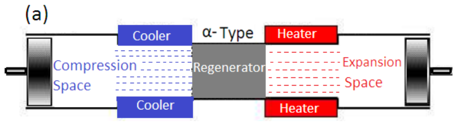
Figure 1. A schematic diagram of a Stirling engine; (a): the α-type engine features two separate cylinders, each containing a piston; (b): the β-type engine incorporates a single cylinder housing both a piston and a displacer; (c): a double-acting Stirling engine including 4 pistons and sinusoidal curve.
Computation 14 00119 g001aComputation 14 00119 g001b
Figure 2. β-type Stirling engine during creating work (w) from high-temperature to low-temperature transformation.
Computation 14 00119 g002
Figure 3. The Carnot cycle; quantities of heat transferred during the isothermal processes in the heat exchangers.
Computation 14 00119 g003
Figure 4. P-V diagram of isothermal transformation for Schmidt model and experimental model.
Computation 14 00119 g004
Figure 5. (a) β -type Stirling engine model including 4 steps between power piston and displacer piston; (b) Carnot cycle of Stirling engine cycle; (c) orientation and parameters of a β -type Stirling engine.
Computation 14 00119 g005
Figure 6. A scheme of a Stirling engine assembled: (a) outer design; (b) inside components.
Computation 14 00119 g006
Figure 7. Flowchart of the CFD–AI-integrated optimization framework for the beta-type Stirling engine.
Computation 14 00119 g007
Figure 8. Power and thermal efficiency with the number of optimized iterations.
Computation 14 00119 g008
Figure 9. A stable simulation with different initial guesses of 10 items from Table 5.
Computation 14 00119 g009
Figure 10. Instantaneous pressure versus volume for item 2 under three temperatures.
Computation 14 00119 g010
Table 1. Three primaries Stirling engine types α, β, and γ according to their distinct operational characteristics and mechanical arrangements.
Engine TypeCylinder ArrangementPiston/
Displacer
Dead VolumePower OutputHot Seal ChallengeAI Optimization Focus
α-type2 cylindersDouble-acting pistonsLowMedium-HighYesCrankshaft & flywheel design, phase angle optimization
β-typeSingle cylinderPiston + displacerLowMediumNoDisplacer motion, pressure and heat transfer optimization
γ-typeSeparate cylindersPiston + displacerMediumHighNoCylinder placement, flow channel, and heat exchanger optimization
Thermodynamic Processes and AI-Assisted Analysis
Engine TypeModeled ProcessesHeat Transfer FocusAI ContributionEfficiency Impact
α-typeIsothermal, adiabatic, realisticRegenerator and coolerOptimize piston dynamics, flow, and heat transferMedium-High
β-typeIsothermal, adiabatic, realisticCompression/expansion zonesDisplacer trajectory prediction, pressure managementMedium
γ-typeIsothermal, adiabatic, realisticSeparation of expansion/compression spacesCylinder placement, flow path, and regenerator optimizationHigh
Table 2. β-type Stirling cycle, the quantities of heat transferred during the isothermal processes.
Heat
Exchange Surface (cm2)
Low
Exchange Surface (cm2)
Minimum Volume
(cm3)
Maximum
Volume
(cm3)
Diameter of Piston
(cm)
Diameter of Stroke Piston (cm) φ 0
190.5369.5189 326 5.94.9105
Rotation speed (rot/s) Q h   (J) Q l   (J) T w h T w l P m a x   (atm)Heat transfer coefficient
(W/m2K)
4.598.157.24203002.280
ExperimentalRDT modelSchmidt Model
W (J) η % W (J) η % W (J) η %
5.155.210.3310.419.19.3
Table 3. Comparison of predicted and experimental pressure and temperature at selected crankshaft angles, demonstrating the predictive accuracy of the AI-assisted Schmidt model.
Crankshaft Angle (°)Pressure Predicted (MPa)Pressure Experimental (MPa)Temperature Predicted (K)Temperature Experimental (K)
00.80.82310312
902.12.05540538
1803.43.45790795
27021.95520525
Engine Speed n (rot/s)Heat Transfer Coefficient h (W/m2K)Efficiency (%)
515038
1020041
1525042
4.58035
Table 4. Baseline parameters.
VariablesSignUnitsValue
Diameter of pistondp(cm)15
Phase θ(deg.)90
Rotational speed ω(rpm)120
Porosity φ-0.95
Displacer of stroke Sd(mm)45
Stroke pistonSp(mm)70
Charged pressure Pch(bar)4.5
High temperature TH(K)450
Cold temperature TC(K)300
Equilibrium position of piston xp(cm)20.5
Working fluidHelium
Efficiency ε(%)17.23
Power W(Wate)170.84
Table 5. CFD calculation results.
Itemω (rpm)Pch (bar)θ (deg.)dp (cm)xp (cm)Sd (mm)TH (K)TC (K)φ(W)ε (%)
11204.5901520.5454503000.95180.3310.32
21204.5901520.5454503000.90185.4411.54
31304.5901620.5444503000.90200.0510.23
41104.5901520.4454503000.95199.4410.58
51205.0901720.5404503000.93205.5411.22
61204.5901520.3424503000.90210.3310.05
71305.0901720.4434503000.93220.5410.29
81105.5951620.3414503000.92188.5410.99
91105.5951720.4424503000.93187.3410.23
101205.5951620.4414503000.96190.3411.09
111105.5951520.5454503000.91200.3510.24
121005.51001620.6434503000.94178.3411.03
131004.01001720.4444503000.94201.8810.21
141104.51001520.3404503000.95205.2210.39
15904.01001520.4454503000.90210.3210.66
16906.0901620.4434503000.90198.4511.22
17905.0901620.3394503000.90188.4410.33
18806.0901720.4434503000.91193.239.99
191005.0901620.5424503000.92184.3310.45
20806.0901720.5454503000.90200.19.99
Table 6. Optimization of non-monotonically parameters.
ParameterSignUnitsInitial DesignRanges BoundedValue Optimization
Piston diameter dp(cm)1515–1715
Phase angle θ(deg.)9090–10090
Rotation speed ω(rpm)12080–120120
Porosity φ-0.950.90–0.950.90
Displacer stroke Sd(mm)4539–4545
Table 7. Comparison of AI-predicted and simulated optimization results for non-monotonic parameters.
ParameterInitial ValueAI-Predicted Optimized ValueSimulated Optimized ValueIndicated Power (W)Thermal Efficiency (%)Improvement (%)
Rotation speed (rpm)150016151620185.211.55.3
Phase angle (°)909192185.311.525.4
Piston diameter (mm)5051.852185.411.545.5
Displacer stroke (mm)4041.742185.411.545.5
Porosity (%)0.250.2650.27185.411.545.5
Table 8. Average thermodynamic and geometric parameters of the β-type Stirling engine obtained from AI-assisted optimization.
ParameterSymbolUnitAverage Value
Hot heat exchange surface(Ah)cm2190.5
Cold heat exchange surface(Ac)cm2369.5
Minimum volume(V{min})cm3189
Maximum volume(V{max})cm3326
Piston diameter(dp)cm5.9
Stroke diameter(Sp)cm4.9
Phase angle(phi0)degree105
Rotation speed(n)rot/s4.5
Maximum temperature(Th)K420
Minimum temperature(Tc)K300
Maximum pressure(P{max})atm2.2
Heat transfer coefficient(h)W/m2K80
Disclaimer/Publisher’s Note: The statements, opinions and data contained in all publications are solely those of the individual author(s) and contributor(s) and not of MDPI and/or the editor(s). MDPI and/or the editor(s) disclaim responsibility for any injury to people or property resulting from any ideas, methods, instructions or products referred to in the content.