Abstract
This paper presents a multi-constraint topology optimization strategy for rudder structures, integrating additive manufacturing (AM)-related overhang angle and flutter-performance considerations. To the best of our knowledge, this is the first study to couple AM overhang control with mass center (flutter) steering in a single density-based formulation for flight control rudder structures. The approach incorporates constraints on structural volume fraction, overhang angle for AM, and mass center positioning to address multi-function design objectives—structural lightweighting, stiffness, aerodynamic stability, and manufacturability. A build-direction-aware projection filter and a smooth Heaviside mass center constraint are introduced to enforce these requirements during every optimization iteration. The resulting layout converges to a sandwich-type rudder with balanced mechanical performance and AM feasibility. Simulation results show that enforcing overhang constraints reduces support material usage by 46.9% and residual deformation by 14.2%, significantly enhancing AM feasibility. Additionally, introducing center-of-mass constraints improves flutter velocity from 3327 m s−1 to 3759 m s−1, indicating a 6.84% increase over conventional optimization and demonstrating improved dynamic stability. These simultaneous gains in manufacturability and aeroelastic safety, achieved without post-processing, underline the novelty and practical value of the proposed constraint set. The strategy thus offers a practical and efficient design method for high-performance, AM-friendly rudder structures with superior mechanical and aerodynamic characteristics, and it can be readily extended to other mission-critical AM components.
1. Introduction
Rudder structures are essential components in systems requiring high-speed flight and precise control. Their design demands a balance between lightweight construction, high load-bearing capacity, and good flutter performance. Structural optimization provides an effective approach for tailoring material distribution to meet these performance objectives, enhancing stiffness while adhering to mass constraints. As typical thin-walled configurations, stiffened structures offer the combined benefits of low weight and high rigidity, making them ideal for aerospace, marine, and other high-performance engineering applications where structural efficiency is of critical importance.
Topology optimization has been widely applied in various engineering fields, particularly in the aerospace industry. Alain Remouchamps [1] proposed a two-level optimization method that combines topology optimization with geometric parameter adjustment to enhance the structural performance and design flexibility of aircraft pylon structures. Zhu [2] explored the integration of compliance-based topology optimization with detailed size and shape optimization in the design of aircraft components. Kang [3] investigated the reformulation of the topology optimization problem for microsatellite structures into a compliance minimization design under mass moment of inertia constraints, aiming to improve attitude control efficiency while maintaining structural performance. Hansen [4] proposed a multilevel optimization method that integrates evolutionary strategies with finite element-based gradient optimization to achieve concurrent optimization of size and topology for complex aerospace structures. Wang [5] proposed a two-stage optimization framework, in which the stiffened panel is partitioned into characteristic deformation subregions and the stiffener layout is optimized, significantly enhancing the load-bearing capacity of the structure under compressive loading. Zhu [2] summarized the latest developments in topology optimization technologies applied to the design of aircraft and aerospace structures. Due to the highly complex structural forms typically generated by topology optimization, conventional manufacturing methods often struggle to realize such designs or are unable to manufacture them. As a layer-by-layer fabrication method, additive manufacturing (3D printing) offers significant advantages for producing complex geometries with high precision and design flexibility.
Although additive manufacturing (3D printing) eliminates the need for molds or fixtures, which greatly simplifies the fabrication process and enables efficient production of complex, non-standard geometries, it also introduces specific process-related constraints. For example, during the printing process, there is a maximum allowable overhang angle for the bottom surfaces of components (typically between 40° and 50°). When the underside surface angle falls below this threshold, support structures are required to prevent collapse or warping during fabrication [6]. In addition, the removal of support structures not only results in material waste but also reduces production efficiency, particularly when dealing with enclosed structures, where support removal becomes even more challenging. Therefore, it is essential to incorporate manufacturing constraints into the early stages of structural design to achieve seamless integration between design and fabrication. Driven by this approach, an increasing number of studies have integrated additive manufacturing constraints (such as the overhang constraint) with topology optimization to enhance the manufacturability of optimized structures. He [7] proposed a method that incorporates overhang constraints into both layout and geometry optimization processes, achieving self-supporting designs while further improving computational efficiency. Vanek [8] performed topology optimization of the length and size of support structures based on adjusted printing orientations, achieving further reduction in branched support structures. Langelaar [9] developed a self-supporting mathematical model based on the maximum density of support regions. However, this method is limited by the type of mesh elements and can only enforce an overhang constraint of 45 degrees. Luo [10] proposed a self-supporting topology optimization method based on the density-based approach, aiming to control the minimum overhang angle of enclosed cavities and address the issue of enclosed voids that may arise after optimization. Gaynor [11] achieved self-supporting topology design based on the SIMP method by employing a density projection approach, where only elements satisfying the overhang angle constraint are projected as solid elements. Han [12] conducted topology optimization using the BESO method based on hybrid additive–subtractive manufacturing technology, comprehensively considering self-supporting constraints from additive manufacturing and milling constraints from subtractive manufacturing, thereby achieving self-supporting structural designs with higher dimensional accuracy.
On the other hand, the rational control of the center of mass is also of critical importance in engineering practice. Zhou [13] established a mathematical model for the topology optimization of continua considering mass and inertia properties, and applied it to both static and eigenfrequency problems. In addition, center of mass control is also regarded as an effective method for flutter suppression in aircraft design. Li [14] analyzed the effects of slider structural parameters, such as axial position, lateral offset, and mass ratio, on the trim angle of attack for aircraft. The results indicated that aerodynamic drag and the offset of the center of mass from the longitudinal axis of the body are the two necessary factors for generating the trim angle of attack. Tang [15] studied the influence of center of mass position on the dynamic characteristics of stratospheric airships. The results showed that slight perturbations of the center of mass not only alter the damping characteristics of the pitching motion but also affect the frequency response of the yaw attitude. Flutter, as a form of self-excited vibration that may be triggered under high-altitude and high-speed conditions, exhibits non-decaying amplitude over time and, in extreme cases, can lead to structural failure. Mu [16] investigated active control methods to modify the structural stiffness, while Zhang [17] utilized the unique mechanical properties of metamaterials to alleviate flutter issues partially; however, such approaches often suffer from high costs and implementation complexity. Cao [18] proposed an improved level set method incorporating center of mass constraints to achieve structural lightweighting, and applied this method to the optimization of a trapezoidal rudder. Numerical analysis demonstrated that adjusting the center of mass position can have a positive impact on flutter suppression performance. Phongkumsing [19] improved the flutter resistance of bridge structures by placing specific counterweights to adjust the center of mass position, thereby reducing aerodynamic moments. Overall, center of mass control not only helps optimize the spatial distribution of structural mass but also effectively adjusts the inertial properties of the system.
This study focuses on the design of the rudder structure and performs topology optimization using the density-based method. Through structural analysis, key additive manufacturing constraints, including build direction, maximum overhang angle limitation, and mass center control, are incorporated while ensuring structural stiffness. The optimized rudder sandwich structure simultaneously achieves high structural performance and manufacturability. This reduces the reliance on support structures during printing and improves both manufacturing efficiency and the structural engineering applicability.
2. Optimization Method
The skin surface of the rudder structure exhibits noticeable curvature and deviation from a single horizontal plane. As a result, using a standard build direction shown in Figure 1a would lead to extensive overhangs that are difficult to support effectively. Additionally, the internal stiffeners in traditional sandwich-type rudder designs typically extend radially from the rudder control shaft toward the outer surface in a branched pattern, further complicating support requirements when printing in the vertical direction. To address these challenges, this study adopts the build direction shown in Figure 1b as the principal printing orientation. This orientation aligns better with the geometry of the rudder structure, minimizes the warp deformation, improves skin surface quality, and significantly reduces the need for supporting materials, thereby enhancing overall manufacturing efficiency.
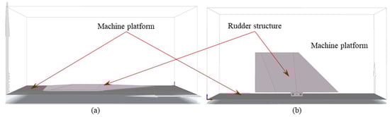
Figure 1.
Build direction for the rudder structure: (a) build direction 1 for the rudder, (b) build direction 2 for the rudder.
2.1. Additive Manufacturing-Related Overhang Constraints
During the additive manufacturing process, components are fabricated layer by layer along the build direction, typically perpendicular to the machine platform. The overhang angle refers to the angle formed between an overhanging surface and the plane of the machine platform. According to current additive manufacturing process standards, when the overhang angle is greater than a critical range of approximately 40° to 50°, the structure can be printed without the need for support. However, if the overhang angle is smaller than this threshold, additional support structures are required to prevent geometric instability, such as sagging or warping. As shown in Figure 2, when the overhang angle exceeds the critical overhang angle, the component can be printed directly without supports. Conversely, when the overhang angle is smaller than the critical angle, support structures are necessary to ensure the part quality and the stability of the printing process [20]. In the layer-by-layer additive manufacturing process, the printability of a material point largely depends on whether adequate support exists beneath it. Within the finite element framework, each material point corresponds to a finite element. In this work, the projection function-based overhang constraint [21] is used.
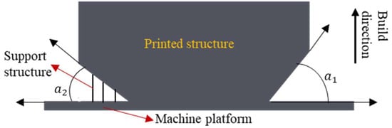
Figure 2.
Schematic illustration of overhang angles and support structures.
In this method, three variables are used, which are , , and Si. indicates whether material is retained at a given location, and represents “material placement variable”, which determines whether material will be projected to the density design variable space, which is defined as
To quantitatively evaluate whether a finite element is adequately supported during the layer-by-layer manufacturing process, the equivalent support indicator is calculated as follows:
where T is the threshold value, which varies between 0 and 1. is a projection parameter. is a penalization parameter. is the average of the material placement variables, ϕ, for a particular point, i, and is defined in the following equation:
where ws is the support region weighting function, and j is a counter of ϕ in the support neighborhood set, .
2.2. Mass Center Constraint
For the rudder structure, the mass center position has a significant effect on the flutter performance. Appropriately adjusting the structural mass distribution can enhance the overall stability and vibration resistance. For the topology optimization problem based on the density method, a class of smooth characteristic functions is usually introduced over the design region to represent the existence of the material ( is a design variable), and then the expression for the mass center in the continuous domain is constructed.
For this purpose, the structural mass center can be defined as the mass-weighted average of the material distribution, which is mathematically expressed as follows:
where is the position vector.
To avoid the numerical discontinuities inherent to a step function, is approximated by the following smoothed Heaviside projection:
Here, is the projection steepness controlling the smoothness of the transition, and is the threshold parameter (typically ). In the numerical implementation, a continuation scheme gradually increases (e.g., from 1 to 24) during the optimization so that evolves from a smooth approximation to a near-binary indicator, thus ensuring both numerical stability and crisp final boundaries.
When the value of approaches 1, indicating the presence of solid material; otherwise, it approaches 0, corresponding to a void region.
In the practical finite element implementation, the above integral relations can be transformed into a discrete weighted average form for numerical evaluation.
In the above equation, represent the density, volume, and mass center coordinate of the element, respectively is the normalized weight; and is the total number of elements. To control the position of the mass center during optimization, the following inequality is used:
This constraint characterizes the distance between the computed mass center and the target position in terms of global integral deviation and ensures that it remains within an acceptable tolerance . This helps maintain structural stability during the topology evolution process.
2.3. Mathematical Optimization Model
According to practical requirements, the topology optimization mathematical model for the rudder structure, based on minimum compliance under a volume constraint, can be formulated as follows:
where is the design variable; is the structural compliance; is the load vector; is the nodal displacement vector; is the global stiffness matrix; is the element displacement vector for the i-th element; is the element stiffness matrix; is the penalty function; is the volume in optimization process; is the Initial structural volume; is the Volume upper limit; is the volume of i-th element; is the volume fraction; is the lower bound of the design variable; is the upper bound of the design variable; is the overhang surface angle of element e; is the threshold corresponding to the overhang critical angle, here set as 45°; is the mass center position of the optimized structures; is the lower bound of the mass center position; and is the upper bound of the mass center position.
In this work, the density-based method is used to identify the structural configuration. The SIMP-based material interpolation scheme is used to obtain the material layout; thus, Young’s modulus can be expressed as
where is a small value to avoid numerical instabilities; is the elastic modulus of the solid material; is the design variable, which is the density of the i-th element; when = 1, it indicates that the element is solid; when = 0, it represents the absence of material, corresponding to a void element. is the penalty factor.
To avoid mesh dependency in the topology optimization problem, the Helmholtz-type partial differential equation (PDE) filter is utilized [22]:
where is the filtered design variable and is the filter radius. To reduce the gray area (intermediate density) between solids and fluids, the hyperbolic tangent projection method is applied to the filter design field [23]:
where is the output design variable. is the projection threshold parameter, here . And is a parameter controlling the projection steepness, set .
Firstly, the design domain is given an initial guess. In this study, a uniform density field with a density value of 0.45 is used as an initial guess. Secondly, based on the initial guess, the finite element analysis is used to solve the governing equations. Thirdly, the objective function and constraints are computed. Finally, a sensitivity analysis is conducted, and design variables are updated. The optimization iteration stops when the following condition is satisfied:
Figure 3 is the workflow of the topology optimization design procedure. First, the design model is discretized into a finite element model, and a design variable is assigned to each element. Next, the structural compliance of the component is computed by solving the governing equations. The sensitivities of the objective and constraint functions are then evaluated, and the design variables are updated until convergence is achieved. The convergence criterion is that the change in the objective function between two successive iterations is smaller than the prescribed tolerance.
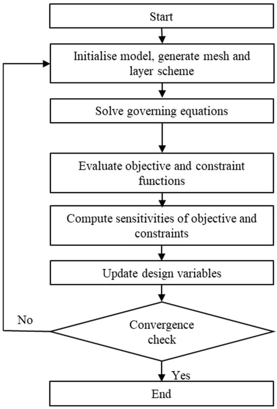
Figure 3.
Topology optimization design flowchart.
2.4. Design Procedure
The optimal material layout can be obtained by solving the mathematical optimization model expressed in Equation (5). The proposed topology optimization process for the rudder structure is illustrated in Figure 4, which contains the following steps:
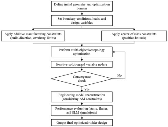
Figure 4.
Design flowchart of proposed topology optimization method considering additive manufacturing-related overhang and mass center constraints.
- (1)
- Define the design domain for the rudder structure and the design variables, then set the boundary and load conditions.
- (2)
- Define an overhang constraint based on the additive manufacturing build direction to ensure both manufacturing feasibility and set the allowable range for the mass center position to improve the flutter performance.
- (3)
- A topology optimization model is then formulated, incorporating constraints on volume, stiffness, manufacturing adaptability, and center of mass regulation. The model is solved using the SIMP method, with design variables iteratively updated until the performance objectives are satisfied and convergence is achieved.
- (4)
- Upon completion of the optimization process, engineering modeling is performed. Practical manufacturing requirements, including additive manufacturing constraints, are fully considered to generate a final sandwich-type rudder structure that achieves both high structural performance and manufacturability.
3. Design Verification
3.1. Design of the Rudder Based on the Proposed Method
The cross-section of the solid-core rudder structure is shown in Figure 5a. The rudder structure is divided into three parts, which are the surface skin, the internal solid-core region, and the rudder shaft. Among these, the internal solid region serves as the design domain for topology optimization, while the skin and the shaft are non-design domains. The total weight of the solid-core rudder structure is 1.514 kg. Titanium alloy is used as the structural material, and its properties are listed in Table 1. The applied aerodynamic-and-inertial-load case corresponds to the worst-case operating condition (maximum dynamic pressure) within the flight envelope. The loads are applied on the surface of the rudder, the load direction is perpendicular to the surface, and the magnitude of the load gradually decreases from the leading edge to the trailing edge [24]. All six degrees of freedom of the cylindrical holes at the rudder shaft are constrained, as shown in Figure 5b.
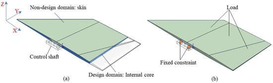
Figure 5.
The rudder structure: (a) cross-sectional view, (b) boundary condition.

Table 1.
Material properties of the control surface structure.
Based on the mathematical model shown in Equation (5), the optimization model for the design of rudder structures with high flutter performance is created. In order to minimize the usage of supporting materials, the overhang constraint is typically set to 45° relative to the x-axis to enhance self-supporting capability. To improve the flutter performance, the mass center is constrained in the X-axis direction during the optimization process, with values ranging from −250 mm to 12.5 mm (based on the center of mass coordinate from the empirical design). In addition, the minimum feature size is set to 15 mm.
Based on the above optimization mathematical model and parameters, topology optimization for the rudder structure is performed, with its iteration histories shown in Figure 6. The left vertical axis is the objective function, and the horizontal axis indicates the iteration steps. In addition, the figure also shows intermediate results corresponding to the 40th, 80th, 120th, and the final convergence iteration steps. In the optimization process, the internal material layout grows towards the leading and trailing edge, and finally, a tree-like structural configuration is obtained. Based on the optimized material layout shown in Figure 7a, the engineering-designed rudder structure is shown in Figure 7b, and the angle of the stiffener meets the 45° overhang angle constraint relative to the horizontal machine platform. The mass of the optimized rudder structure is 0.875 kg. The structural features shown in Figure 7b, which feature a tree-like high-stiffness and manufacturable stiffener layout, demonstrate the advantages of the proposed topology optimization method.
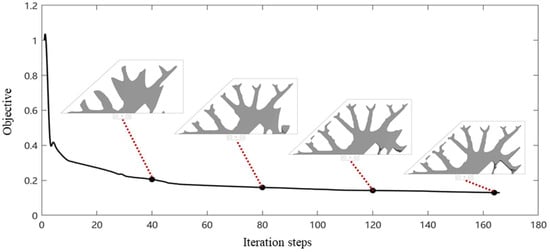
Figure 6.
The iteration histories of the topology optimization.
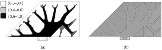
Figure 7.
The optimization result: (a) the material layout, (b) post-processed geometry model.
3.2. Comparative Case Studies
To demonstrate the advantages and effectiveness of the proposed optimization model for rudder structures design, two benchmark cases are conducted, and the results are compared with state-of-the-art methods. For the two comparative examples, one is topology optimization without considering both the overhang and location of center of mass constraints, which is denoted as Comparative case study 1. The mathematical model for the optimization is as follows:
The other comparative example is topology optimization considering only the overhang constraint, which is denoted as Comparative case study 2. The mathematical model for the optimization is as follows:
Both of the examples are based on the same design parameters except for the optimization model. The optimized results are shown in Figure 8a and Figure 8b, respectively. The result of Comparative case study 1, shown in Figure 8a, has a mass of 0.857 kg, while the result of Comparative case study 2, shown in Figure 8b, has a mass of 0.887 kg. From the material layout, it can be found that the Comparative case study 2, which considers the overhang constraint, has enhanced self-supporting capability, reduces the need for additional support material, and improves manufacturability of the rudder.
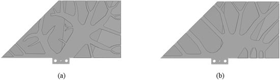
Figure 8.
Design results: (a) Comparative case study 1, (b) Comparative case study 2.
3.3. Performance Comparison
3.3.1. Comparison of Mass Center
The mass centers of each optimized rudder structure are shown in Figure 9. The distance from the mass center to the rotation axis is for the Comparative case study 1, and the distance is for the Comparative case study 2, which considers the overhang constraint. It should be noted that these designs do not account for mass center constraints. The mass center is changed to when considering both of overhang and mass center constraints. Compared with the result of Comparative case study 2, the mass center moves forward by 17.49% after introducing mass center constraints. When comparing with the result of Comparative case study 1, the mass center moves backward by 0.24%, but shows better manufacturability performance. These comparison results demonstrate the effectiveness of the consideration of the mass center constraint to control the mass center of the optimized structure. This also highlights the necessity of integrating mass center constraints alongside manufacturing constraints to achieve a more balanced and effective design.
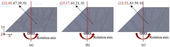
Figure 9.
Mass center of different design results: (a) mass center of Comparative case study 1, (b) Mass center of Comparative case study 2, (c) mass center of result obtained by proposed optimization model.
3.3.2. Comparison of Static Performance
Under the same boundary conditions, static analysis for the three different design results is conducted. The simulation results are shown in Figure 10, in which the maximum displacement of the Comparative case study 1 is 16.368 mm, that of the Comparative case study 2 with the overhang constraint is 16.399 mm, and that of the one with the overhang and mass center constraints is 16.547 mm. Compared with the Comparative case study 1, the maximum displacement of Comparative case study 2 increases about 0.19%, while the maximum displacement of the rudder structure obtained by the proposed optimization model increases by 1.08%. The results show that the proposed optimization model integrates the design of other functions while maintaining structural stiffness and achieves the design of a multifunctional structure.
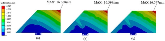
Figure 10.
Displacement nephogram of different design results: (a) displacement nephogram of Comparative case study 1, (b) displacement nephogram of Comparative case study 2, (c) displacement nephogram of result obtained by proposed optimization model.
3.3.3. Comparison of Flutter Performance
The flutter analysis of the three different rudder structures is performed using the p–k method. The boundary condition constrains the six degrees of freedom of the circular holes shown in Figure 5b, and the flight speed is 6 Mach. In the p–k root-locus calculation, we track the eigen-pairs at every speed; the first bending (B1) and second torsional (T2) mode shapes are identified from their modal strain-energy content and used to interpret the instability mechanism. The analysis results are shown in Figure 11, and the critical flutter speed can be determined by evaluating the intersection point in the v-g (velocity-damping) and v-f (velocity-frequency) diagram. At the critical velocity, the B1 and T2 curves in Figure 11 coalesce in frequency, and their damping simultaneously changes sign, confirming a classical bending—torsion coupled flutter rather than a single-mode divergence. This explicit consideration of mode shapes and natural frequencies ensures that the chosen V_F is physically meaningful, not a mere velocity bound. From Figure 11, the flutter speed of the Comparative case study 1 is 3518 m/s, and that of Comparative case study 2 is 3327 m/s. Compared with Comparative case study 1, the flutter speed of Comparative case study 2 decreases by 5.42%. When both the overhang and mass center constraints are considered, the flutter speed increases significantly to 3759 m/s, and has a 6.84% improvement over the Comparative case study 1. These results indicate that the Comparative case study 2, which only considers the overhang constraint, has the worst flutter performance; this is because its mass is far from the rotation axis. By relocating the mass centroid closer to the torsional axis, the combined-constraint design shifts the B1–T2 coupling to a higher speed and thereby enhances aeroelastic stability. The consideration of mass center constraints can effectively affect the flutter performance of the rudder and enhance the aerodynamic stability of the structure.
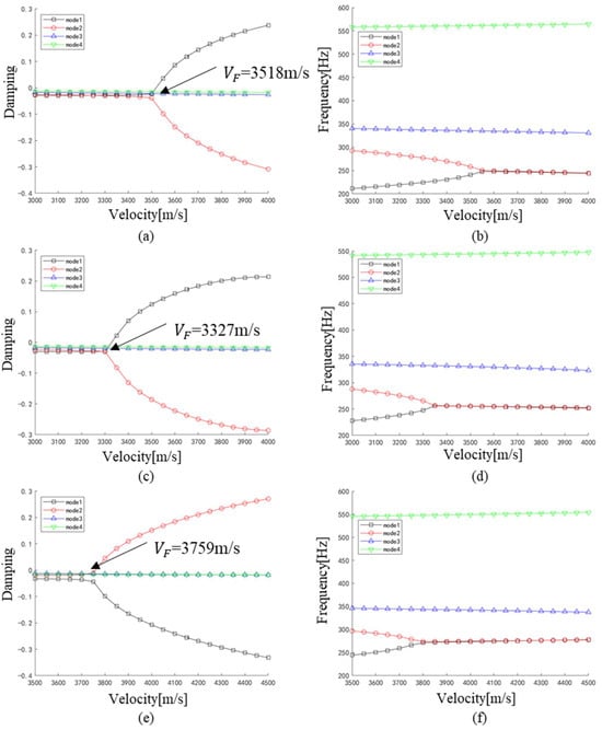
Figure 11.
Flutter analysis results: (a,b) are the v-g and v-f diagrams for the Comparative case study 1, (c,d) are the v-g and v-f diagrams for the Comparative case study 2, and (e,f) are the v-g and v-f diagrams for the optimal result obtained by the proposed method.
3.3.4. Comparison of Manufacturing Process Simulation
The additive manufacturing process simulation of Selective Laser Melting (SLM) was conducted for the three different rudder structures to verify the manufacturability. Ti-6Al-4V was used as the material, and inherent strains (−0.0131, −0.0102, 0.0165) were applied to each element layer by layer using the element birth–death technique [25]. As illustrated in Figure 12, the left column of subfigures shows the rudder structures and their supports, while the right column of subfigures displays the results of residual deformation. For Comparative case study 1, about 0.32 kg of internal support material should be added to manufacture this optimized rudder structure, and the maximum residual deformation is 1.20 mm. For Comparative case study 2, the maximum residual deformation decreases to 1.19 mm, and the support material is significantly reduced to 0.17 kg because of the overhang constraint. When both the overhang and mass center constraints are applied, the residual deformation is further reduced to 1.03 mm, while the support material remains at 0.17 kg. It can be concluded that compared with Comparative case study 1, the consideration of overhang and mass center constraints leads to a 14.2% reduction in maximum residual deformation and a 46.9% reduction in support material usage, thereby improving manufacturing efficiency.
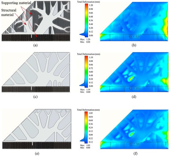
Figure 12.
Schematic of sandwich rudder support structure with SLM simulated residual displacement cloud: (a,b) are optimized rudder structure with supporting and residual deformation nephogram for the Comparative case study 1, (c,d) are optimized rudder structure with supporting and residual deformation nephogram for the Comparative case study 1, and (e,f) are optimized rudder structure with supporting and residual deformation nephogram for the optimal result obtained by proposed method.
3.3.5. Discussion
According to the performance comparison in Table 2, the rudder structure of Comparative case study 1 exhibits the minimum maximum displacement of 16.368 mm, indicating superior stiffness compared with other design cases. The consideration of additive manufacturing-related overhang constraints results in a slight reduction in stiffness, but the optimized structures still show high stiffness performance for practical engineering applications.
Table 2.
Analysis of comparative performance metrics for different constrained sandwich rudders.
In terms of flutter performance, the Comparative case study 1 has a critical flutter speed of 3518 m/s. The flutter speed of Comparative case study 2, which considers the overhang constraint, decreases to 3327 m/s due to the rearward shift in the mass center. When both overhang and mass center constraints are considered, the mass distribution is optimized, and the center of mass shifts forward, the flutter speed increases to 3759 m/s, and shows an improvement of 6.85% over the Comparative case study 1. This demonstrates that the mass center constraint can effectively improve the flutter performance.
From a manufacturing perspective, the consideration of additive manufacturing-related overhang constraints improves self-supporting capability. As a result, support material usage is reduced by 46.9%, and manufacturing efficiency is significantly improved. Additionally, SLM simulation shows that the maximum residual deformation is reduced by 14.2% when both the overhang and mass center constraints are applied, further verifying the effectiveness of the proposed method.
In summary, the proposed topology optimization approach—integrating overhang and mass center constraints—improves the manufacturability and dynamic performance of the rudder structure while preserving fundamental structural stiffness. This approach provides a practical and effective solution for the engineering design of high-performance, additively manufacturable rudder components.
4. Conclusions
In this study, a topology optimization approach for multifunctional rudder structure design is proposed based on the density-based method. Both overhang angle and mass center constraints were simultaneously integrated into the optimization mathematical model to achieve optimized rudder structures with lightweight, enhanced additive manufacturing adaptability and high flutter performance. The main conclusions are as follows:
- (1)
- This study incorporates additive manufacturing overhang constraints into the density-based topology optimization formulation. Self-supporting rudder structures with high stiffness are obtained. The simulation results indicate that the maximum displacement increases by only 1.08% compared to the result of conventional design without overhang constraint, whereas the maximum residual deformation is reduced by 14.2%, and support material usage is decreased by 46.9%. These improvements greatly enhance printing stability and material utilization.
- (2)
- The synergistic integration of mass center constraints with AM-oriented overhang constraints achieves dual optimization: (1) controlled mass redistribution—the mass center deviation is limited to 0.24%; (2) significant improvements in rudder flutter performance, demonstrating 6.85% improvement in flutter analysis, and the critical flutter speed increases from 3327 m/s to 3759 m/s, thereby enhancing aerodynamic stability.
In summary, the developed optimization framework effectively improves additive manufacturing compatibility and flutter performance of rudder structures while maintaining structural stiffness. It provides a practical and implementable strategy for the design of high-performance rudder structures and demonstrates strong potential for engineering applications.
Author Contributions
Conceptualization, H.Z. and X.D.; methodology, H.Z., S.S. and X.D.; software, S.S.; validation, S.S., J.Y. and M.X.; formal analysis, S.S. and M.X.; investigation, H.Z. and S.S.; resources, H.Z. and X.D.; data curation, S.S.; writing—original draft preparation, H.Z. and S.S.; writing—review and editing, H.Z. and S.S.; visualization, S.S. and J.Y.; supervision, H.Z. and X.D.; project administration, H.Z. and X.D.; funding acquisition, H.Z. All authors have read and agreed to the published version of the manuscript.
Funding
This research was funded by National Natural Science Foundation of China grant number 52375257, Shanghai Pujiang Program grant number 24PJD073.
Data Availability Statement
The paper contains an adequate amount of details on the methodology and implementation. All the data generated or analyzed during this study are included in this paper. The data that support the findings of this study are available from the corresponding author upon reasonable request.
Conflicts of Interest
The authors declare that they have no known competing financial interests or personal relationships that could have appeared to influence the work reported in this paper.
References
- Remouchamps, A.; Bruyneel, M.; Fleury, C.; Grihon, S. Application of a bi-level scheme including topology optimization to the design of an aircraft pylon. Struct. Multidiscip. Optim. 2011, 44, 739–750. [Google Scholar] [CrossRef]
- Zhu, J.H.; Zhang, W.H.; Xia, L. Topology Optimization in Aircraft and Aerospace Structures Design. Arch. Comput. Methods Eng. 2016, 23, 595–622. [Google Scholar] [CrossRef]
- Kang, Z.; Wang, X.; Wang, R. Topology optimization of space vehicle structures considering attitude control effort. Finite Elem. Anal. Des. 2009, 45, 431–438. [Google Scholar] [CrossRef]
- Hansen, L.U.; Horst, P. Multilevel optimization in aircraft structural design evaluation. Comput. Struct. 2007, 86, 104–118. [Google Scholar] [CrossRef]
- Wang, B.; Hao, P.; Li, G.; Tian, K.; Du, K.; Wang, X.; Zhang, X.; Tang, X. Two-stage size-layout optimization of axially compressed stiffened panels. Struct. Multidiscip. Optim. 2014, 50, 313–327. [Google Scholar] [CrossRef]
- Kranz, J.; Herzog, D.; Emmelmann, C. Design guidelines for laser additive manufacturing of lightweight structures in TiAl6V4. J. Laser Appl. 2014, 27, S14001. [Google Scholar] [CrossRef]
- He, L.; Gilbert, M.; Johnson, T.; Pritchard, T. Conceptual design of AM components using layout and geometry optimization. Comput. Math. Appl. 2019, 78, 2308–2324. [Google Scholar] [CrossRef]
- Vanek, J.; Galicia, J.A.G.; Benes, B. Clever support: Efficient support structure generation for digital fabrication. Comput. Graph. Forum 2014, 33, 117–125. [Google Scholar] [CrossRef]
- Langelaar, M. An additive manufacturing filter for topology optimization of print-ready designs. Struct. Multidiscip. Optim. 2017, 55, 871–883. [Google Scholar] [CrossRef]
- Luo, Y.; Sigmund, O.; Li, Q.; Liu, S. Additive manufacturing oriented topology optimization of structures with self-supported enclosed voids. Comput. Methods Appl. Mech. Eng. 2020, 372, 113385. [Google Scholar] [CrossRef]
- Gaynor, A.T.; Guest, J.K. Topology optimization considering overhang constraints: Eliminating sacrificial support material in additive manufacturing through design. Struct. Multidiscip. Optim. 2016, 54, 1157–1172. [Google Scholar] [CrossRef]
- Han, S.Y.; Xu, B.; Zhao, L.; Xie, Y.M. Topology optimization of continuum structures under hybrid additive-subtractive manufacturing constraints. Struct. Multidiscip. Optim. 2019, 60, 2571–2595. [Google Scholar] [CrossRef]
- Zhou, P.; Ou, G.; Du, J. Topology optimization of continua considering mass and inertia characteristics. Struct. Multidiscip. Optim. 2019, 60, 429–442. [Google Scholar] [CrossRef]
- Li, R.; Gao, C.; Jing, W.; Qian, Y. Moving mass control and performance analysis for aerospace vehicle. J. Astronaut. 2010, 31, 2165–2171. [Google Scholar]
- Tang, J.; Bai, S.; Xie, W.; Wu, J.; Jiang, H.; Sun, Y. Analysis of Influence of Stratospheric Airship’s Key Parameter Perturbation on Motion Mode. Aerospace 2023, 10, 329. [Google Scholar] [CrossRef]
- Xusheng, M.; Rui, H.; Qitong, Z.; Haiyan, H. Machine learning-based active flutter suppression for a flexible flying-wing aircraft. J. Sound Vib. 2022, 529, 116916. [Google Scholar] [CrossRef]
- Xiaopeng, Z.; Yuewu, W.; Wei, Z. Vibration and flutter characteristics of GPL-reinforced functionally graded porous cylindrical panels subjected to supersonic flow. Acta Astronaut. 2021, 183, 89–100. [Google Scholar] [CrossRef]
- Cao, Q.; Dai, N.; Bai, J.; Dai, H. A dimensionality reduction optimization method for thin-walled parts to realize mass center control and lightweight design. Eng. Optim. 2024, 57, 1291–1307. [Google Scholar] [CrossRef]
- Phongkumsing, S.; Wilde, K.; Fujino, Y. Analytical study on flutter suppression by eccentric mass method on FEM model of long-span suspension bridge. J. Wind Eng. Ind. Aerodyn. 2001, 89, 515–534. [Google Scholar] [CrossRef]
- Wang, D.; Yang, Y.; Yi, Z.; Su, X. Research on the fabricating quality optimization of the overhanging surface in SLM process. Int. J. Adv. Manuf. Technol. 2013, 65, 1471–1484. [Google Scholar] [CrossRef]
- Andrew, T.G.; Johnson, T.E. Eliminating occluded voids in additive manufacturing design via a projection-based topology optimization scheme. Addit. Manuf. 2020, 33, 101149. [Google Scholar] [CrossRef]
- Lazarov, S.B.; Sigmund, O. Filters in topology optimization based on Helmholtz-type differential equations. Int. J. Numer. Methods Eng. 2011, 86, 765–781. [Google Scholar] [CrossRef]
- Wang, F.; Lazarov, S.B.; Sigmund, O. On projection methods, convergence and robust formulations in topology optimization. Struct. Multidiscip. Optim. 2011, 43, 767–784. [Google Scholar] [CrossRef]
- Wang, Q.; Ding, X.; Shi, X.; Li, H.; Zhang, H. Concurrent topology optimization for double-skin stiffened structures considering external shape and modal characteristics. Struct. Multidiscip. Optim. 2025, 68, 49. [Google Scholar] [CrossRef]
- Yan, X.; Yang, R.; Lian, G.; Jie, Y. Residual deformation prediction in metal 3D printing process based on modified inherent strain theory. Appl. Laser 2023, 43, 29–36. [Google Scholar]
Disclaimer/Publisher’s Note: The statements, opinions and data contained in all publications are solely those of the individual author(s) and contributor(s) and not of MDPI and/or the editor(s). MDPI and/or the editor(s) disclaim responsibility for any injury to people or property resulting from any ideas, methods, instructions or products referred to in the content. |
© 2025 by the authors. Licensee MDPI, Basel, Switzerland. This article is an open access article distributed under the terms and conditions of the Creative Commons Attribution (CC BY) license (https://creativecommons.org/licenses/by/4.0/).