Article

Pentaband Dual-Polarized Antenna for Multiservice Wireless Applications

1
Department of Electronics and Communication Engineering, Koneru Lakshmaiah Education Foundation, Vaddeswaram 522302, AP, India
2
Department of Electronics and Communication Engineering, Gokaraju Rangaraju Institute of Engineering and Technology, Hyderabad 500090, TS, India
*
Author to whom correspondence should be addressed.
Computation 2023, 11(4), 76; https://doi.org/10.3390/computation11040076
Submission received: 26 February 2023 / Revised: 28 March 2023 / Accepted: 3 April 2023 / Published: 8 April 2023

Abstract

:
This paper presents a novel design for and an experimental study of a dual-polarized quad-port MIMO antenna. The design achieves resonance at five distinct frequency bands with reduced mutual coupling. The design includes a single annular ring slot, four truncated rectangular corners, and a truncated aperture to improve resonance behavior. The design is then extended to a four-port MIMO antenna by including a ground-plane slit to enhance isolation between antenna elements at the center resonance band. The antenna achieves resonances at 5 distinct bands, ranging from 1.5 to 8.4 GHz, with significant mutual coupling reductions. The resonances of the quad-port pentaband MIMO antenna are achieved at 1.55 GHz (1.5–1.65 GHz), 2.5 GHz (2.4–2.7 GHz), 5.2 GHz (5–5.85), 7.3 GHz (7.1–7.4), and 8.15 GHz (7.9–8.4), with respective mutual coupling reductions of 27 dB, 37 dB, 21 dB, 29 dB, and 21 dB. Additionally, the 3 dB axial ratio bandwidth (ARBW) is observed at 6.5% (1.5–1.6 GHz) and 15% (2.4–2.7 GHz) in 2 distinct bands, and the envelope correlation coefficient and diversity gain are calculated within the specified band range. Experimental measurements of the prototype for the quad-port antenna are conducted, with excellent agreement found between the results and the simulations.

1. Introduction

Wireless communication has become an integral part of modern society, and as the demand for wireless services continues to grow, industries are seeking ways to provide reliable and efficient wireless communication across multiple frequency bands [1,2,3,4]. Multiband technology has emerged as a solution to this problem, as it allows for the use of multiple frequency bands simultaneously, thereby improving spectral efficiency, increasing channel capacity, and reducing multipathing. One type of antenna that is particularly useful for multiband operation is the printed patch antenna. Printed patch antennas are cost-effective, are easy to implement, and can communicate across multiple bands, making them an attractive option for wireless communication applications. However, to fully realize the benefits of multiband technology, it is essential to combine it with multiple-input–multiple-output (MIMO) systems [5]. MIMO technology enables high spectral efficiency, high data rates, and reliable communication between sending and receiving terminals. Compared to a single antenna, MIMO systems offer significant advantages, making them crucial components of modern wireless communication [6,7,8].
As the demand for wireless communication continues to grow, there has been a significant increase in the development of multiband MIMO antenna concepts for existing wireless systems in recent years [9,10]. However, designing MIMO antennas presents a primary challenge of reducing the coupling between adjacent antenna elements [11]. Reducing the coupling between antenna elements is essential, as it directly impacts the system’s throughput [12]. Therefore, various decoupling strategies have been explored in the literature, including using a slit on the ground plane, neutralization lines, parasitic structures, frequency-selective surfaces, and artificial metamaterials.
For instance, some researchers have proposed using slots on the ground plane to achieve decoupling in dual-band MIMO antennas [13], while others have applied the neutralization technique to ultrawideband structures to reduce mutual coupling [14,15]. However, these decoupling methods have limitations and may not be suitable for all applications. Other researchers have proposed more complex decoupling strategies, such as using parasitic structures, frequency-selective surfaces, and artificial metamaterials [16,17,18]. These designs are generally used for single narrow-band applications and utilize multilayer structures, making the design more complex.
In previous studies, researchers have explored multiband MIMO antennas with dual ports [19,20,21,22,23] and quad/multiport ports [24,25,26,27,28,29]. The dual-port antenna design proposed in [19] utilized a defective ground and parasitic element to create a dual-band antenna suitable for WLAN applications. In another study [20], stubs were integrated into the feedline and ground plane to achieve 20 dB isolation in tri-arm triple-band MIMO operation. In a third design [21], researchers proposed 3 iterations of a hexagonal aperture on a hexagonal patch for pentaband applications, which achieved over 21 dB isolation with a defective ground.
More recently, a study focused on a planar log-periodic array that achieved 23.5 dB of element isolation without decoupling structures for Ku/K-band wireless communications [22]. This design utilized a log-periodic antenna element and a specific feed network to realize multiband MIMO performance without decoupling structures. Additionally, an E-shaped compact MIMO antenna was proposed for pentaband applications [23], although it achieved very low isolation.
Compared to dual-port models, achieving high isolation in multi-port antennas becomes more challenging as the number of elements increases due to increased coupling effects. One approach to achieving high isolation among antenna elements is to incorporate circular and rectangular slots on a square-shaped patch, which was used to achieve 16 dB isolation below 6 GHz across the three operating bands of 5G [24]. In another design, a square-ring slot radiator was used to develop a triple-band antenna for 4G and 5G mobile terminals, achieving 16 dB isolation [25]. Similarly, an asymmetric co-planar strip G-shaped structure was proposed for another triple-band antenna with 18 dB isolation [27]. Additionally, a four-element antenna for quad-band applications that used meander-line-based radiators exhibited more than 22 dB isolation [28]. Another approach involves the use of decoupling networks to improve isolation between antenna elements. For example, a six-element four-band MIMO antenna was proposed for IoT/WLAN/Sub-6 GHz/X-band applications, utilizing a decoupling network [29]. However, this design achieved a low level of isolation. It is important to note that all the approaches mentioned above employed linear polarization (LP).
Recently, circular polarization (CP) has gained attention as a promising technique to enhance the performance of MIMO antennas in wireless communications. CP MIMO antennas have been reported to offer advantages such as reduced fading and better channel capacity compared to LP MIMO antennas [30]. Therefore, developing CP MIMO antennas with high isolation is a promising avenue for future research. Several CP MIMO antennas have been proposed in the literature, including dual circular polarization [31,32]. However, there are only a few research papers that demonstrate simultaneous LP and CP in single multiband MIMO antennas [33,34,35]. Dual-polarization antennas enable multiband operations with high isolation between nearly radiating bands, leading to better reception.
For instance, a tri-band MIMO antenna was proposed to cover the LP GSM band, WLAN band, and WiMAX band with CP [33]. In another triple-band MIMO design, the first two bands use LP, and the third band uses CP [34]. Furthermore, a meander-line pentaband MIMO antenna with circular polarization was proposed for mobile satellite services and internet-of-things applications [35]. However, despite these advancements, there is still a need to provide dual polarization that covers other frequency bands. This can be achieved through further research and development of CP MIMO antennas with high isolation, which will lead to better performance in wireless communication systems [33,34,35].
In the search for high-performing antennas for wireless communication applications, a new design has emerged that offers both circular polarization and multiband capabilities. The proposed design presented in this study offers a simple yet effective solution to achieving pentaband coverage with dual circular polarization. The design uses a rectangular patch with an asymmetric edge slot, truncated to create a triple band, and an annular ring slot with stepped apertures of different sizes to achieve pentaband coverage. This design is a significant improvement over previous designs that have only demonstrated either LP or CP in single- or dual-band MIMO antennas. For instance, the proposed design covers navigation, WLAN, and fixed/mobile satellite communication applications with a slight deviation in the resonance frequency without disrupting the bands. Moreover, the proposed design is also extended to quad-port MIMO, where a ground slit is incorporated to achieve over 20 dB of isolation. The diversity parameters of the proposed dual-polarized antenna design, such as the envelope correlation coefficient (ECC) and diversity gain (DG), show that the design is well-suited for MIMO applications. A comparison of the proposed design with existing cited references is provided in Table 1.
The table compares various dual-polarized antennas with the proposed design in terms of dimensions, operating bands, number of ports, polarization, and isolation. The antennas in the table operate with dual-, triple-, quad-, and pentaband coverages and have LP or CP polarizations. The proposed design is a pentaband dual-polarized antenna with 4 ports and achieves an isolation of 21 dB. The dimensions of the proposed antenna are 62 × 62 × 1.6 mm3. The proposed design offers a competitive performance compared to the other designs in the table.

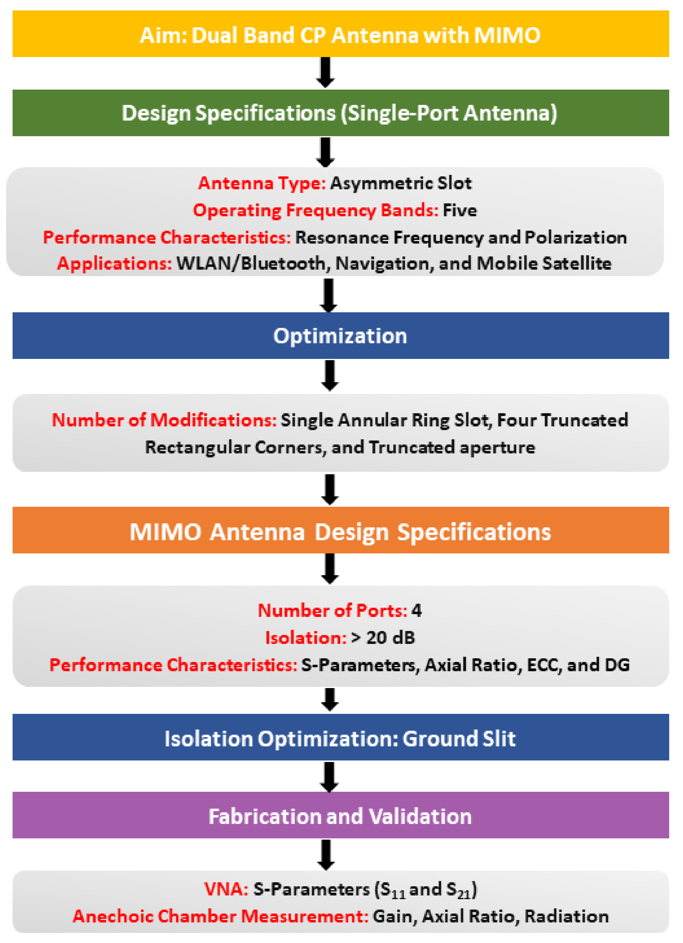
2. Proposed Antenna Configuration and Description

Figure 1 provides a systematic representation of the various stages involved in the design process of the dual-polarized pentaband antenna. It highlights the various stages that were followed, including the initial design and simulation phase, followed by the fabrication and testing of the antenna. The design process involved various stages, including the selection of the antenna type, defining the operating frequency range, antenna geometry optimization, simulation, and prototyping. Furthermore, the subsequent sub-section elaborates on the design process and results of a multiband antenna geometry with a single port. It provides detailed insights into the optimization process and performance characteristics of the antenna. Following this, the next sub-section discusses the geometry and characteristics of the quad-port configuration, highlighting the diversity performance of the proposed MIMO antenna.

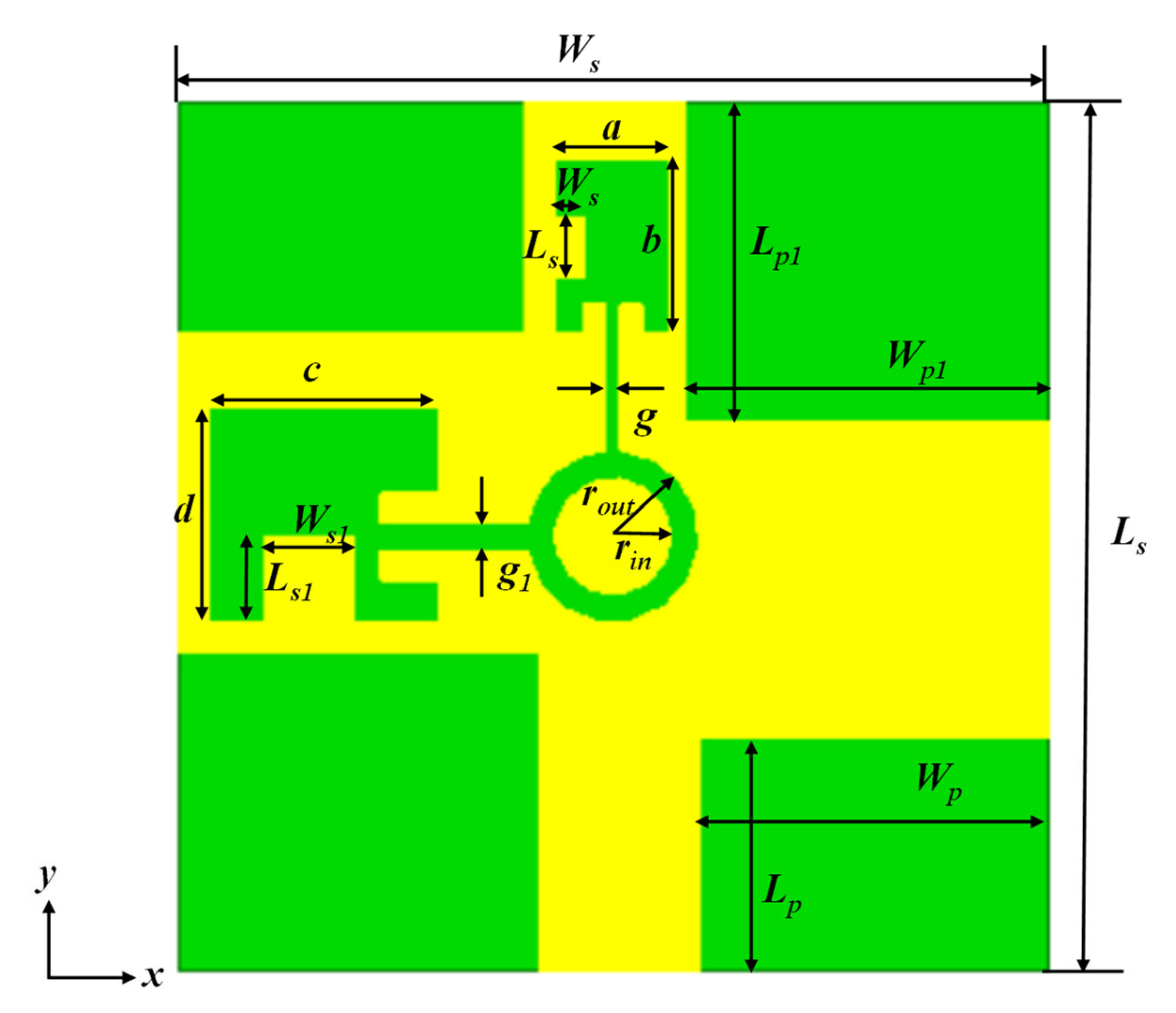
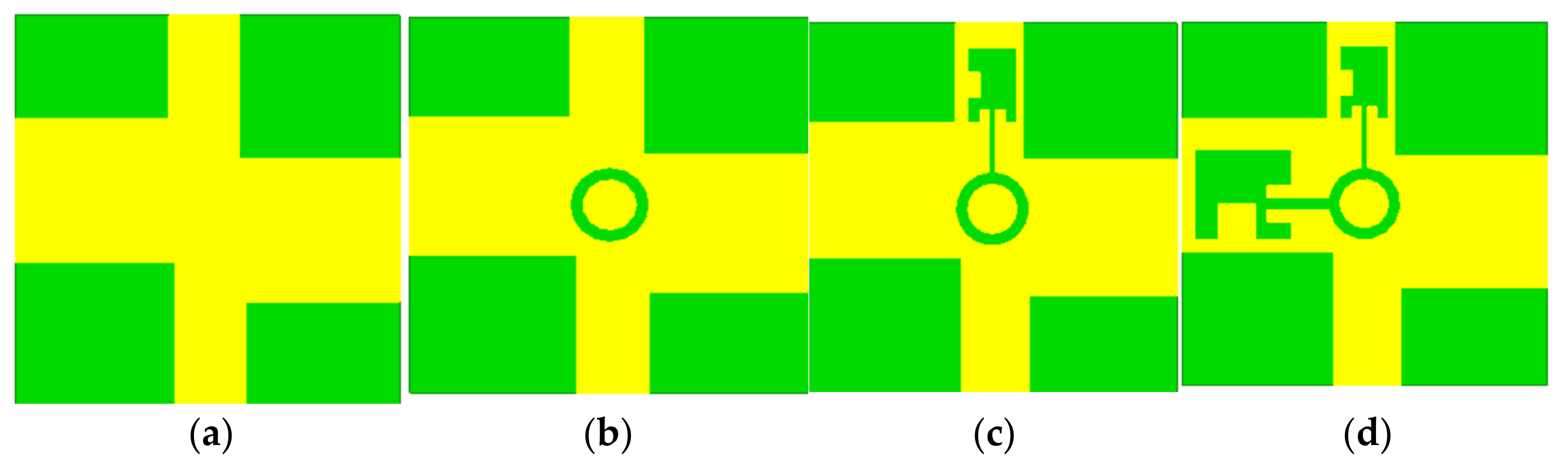
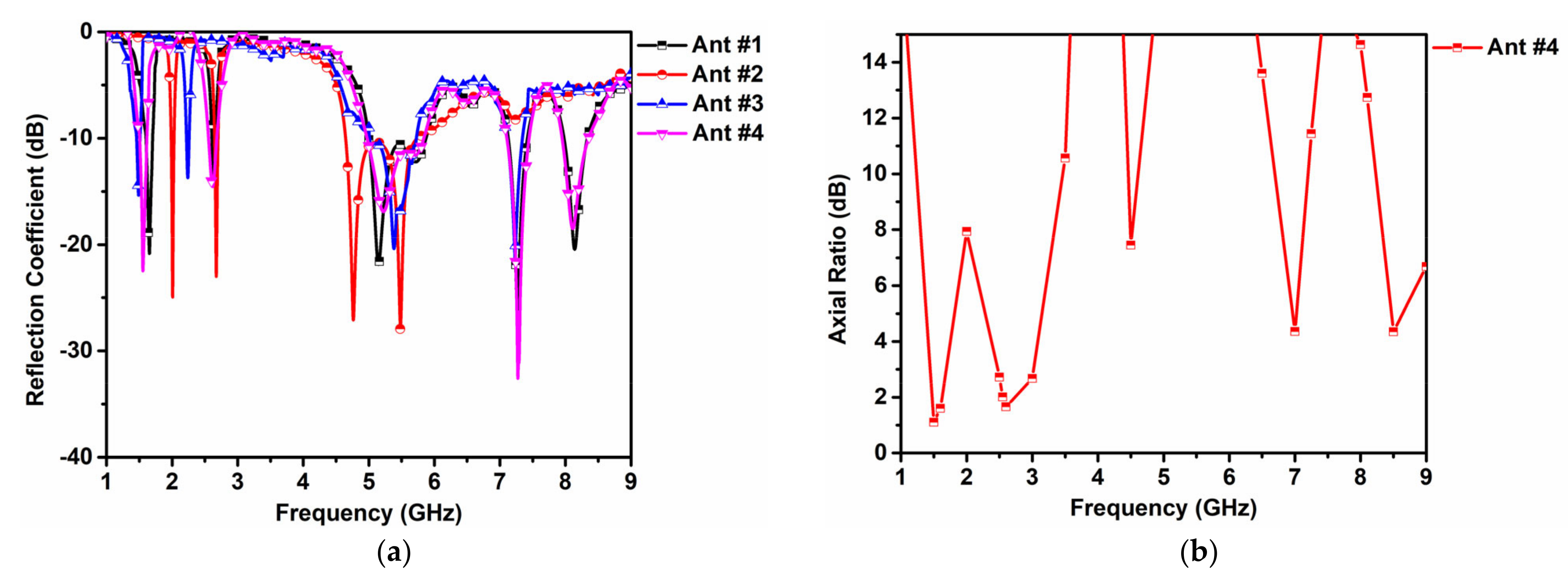
2.1. Single-Port Antenna Element

Figure 2 illustrates the proposed geometry of the single-port antenna designed for pentaband resonance characteristics. The design includes an asymmetric truncated slot and a stepped aperture of different sizes at the quadrature position on the patch. By etching the asymmetric truncated slots on the patch, three resonance frequencies are produced. Additionally, inserting an annular ring improves the bandwidth of the third band. To achieve pentaband performance, a stepped aperture configuration is etched on the top and left portion of the patch, and the slot is extended to the annular slot. It is essential to note that the proposed design’s unique geometry is crucial in achieving pentaband resonance characteristics. The asymmetric truncated slots, stepped aperture configuration, and annular ring all work together to produce the desired frequency response. The geometry is designed on an FR-4 substrate with a relative permittivity of 4.4 and overall dimensions of 30 × 30 × 1.6 mm3. A ground plane is located on the opposite side of the substrate to cover the entire substrate. Table 2 in this paper provides further information on the design parameters and their respective dimensions.
The pentaband resonance approach achieves multiband operation by manipulating the current distribution on the patch antenna using different configurations of slots and apertures. The design process presented in Figure 3 demonstrates how this approach can be used to achieve five resonance frequencies in a single antenna. The design process begins with an initial step wherein a square patch is truncated asymmetrically to operate at the triple-resonance frequency, as shown in Figure 3a. This truncated patch is called Ant #1. In the second step, an annular ring slot is added to Ant #1 to modify the current distribution, resulting in a shift of the triple-resonance characteristics towards the lower-frequency side and dual resonances in the third band. The modified patch is called Ant #2, and it is shown in Figure 3b.
In the third step, Ant #2 is further modified by etching a stepped aperture configuration to form Ant #3, generating four resonance frequencies and shifting the lower two resonance bands further down. Figure 3c depicts Ant #3 after this step. Finally, in the last step, a fifth resonance band is added by creating another stepped aperture configuration in Ant #3, as shown in Figure 3d. This final design is the proposed pentaband antenna.
In Figure 4a, the reflection coefficients obtained from the simulation for Ants #1 to #4 are shown. The reflection coefficient is a measure of how much energy is reflected back from the antenna, and it is related to the antenna’s impedance. The resonance frequency of an antenna is the frequency at which the reflection parameter is minimum, indicating that the antenna is effectively matched to the transmission line. Ant #1 exhibits resonance frequencies at 2.4 GHz (2.38 GHz–2.45 GHz), 3.5 GHz (3.35 GHz–3.65 GHz), and 6.3 GHz (6 GHz–6.6 GHz), while Ant #2 operates at 2 GHz, 2.7 GHz, and 5.4 GHz bands. Ant #3 and Ant #4 exhibit 2 additional resonances at the higher-frequency side at 7.3 GHz and 8.4 GHz, with a slight shift in the lower 2 frequency bands.
The pentaband antenna design achieves impedance bandwidths of 9.5% (1.5–1.65 GHz), 15% (2.4–2.7 GHz), 15.6 % (5–5.85 GHz), 4 % (7.1–7.4), and 6 % (7.9–8.4) in 5 separate bands. The antenna also provides circular polarization (CP) at 2 distinct bands with an ARBW of 6.5% (1.5–1.6 GHz) and 15% (2.4–2.7 GHz).
In Figure 4b, the axial ratio performance for the designated bands is shown. The pentaband antenna demonstrates stable and uniform CP across all 5 resonance bands with a maximum axial ratio of 3.3 dB. This suggests that the proposed design is suitable for a wide range of wireless communication applications that require high performance and versatility.
Further, the CP behavior of the proposed antenna is analyzed using the surface current distribution, as shown in Figure 5. The figure shows the CP bands at 1.5 GHz and 2.6 GHz. From the current distribution in Figure 5a, it is observed that the current on the top middle portion of the patch rotates in an anticlockwise direction over time, with different phases of 0°, 90°, 180°, and 270° at 1.5 GHz from left to right, respectively. This rotating current distribution generates a circular polarization in the radiated field. Additionally, the top left portion of the patch also exhibits current distribution in the same direction at 2.5 GHz, indicating that the antenna possesses CP characteristics at this frequency as well.
The CP performance of the proposed antenna is further analyzed in terms of the ARBW, as shown in Figure 4b. The ARBW is 6.5% (1.5–1.6 GHz) and 15% (2.4–2.7 GHz), indicating that the antenna provides CP at 2 distinct frequency bands. The ARBW refers to the range of frequencies over which the magnitude of the ratio of the major and minor axes of the ellipse that describes the polarization of the radiated field remains below a certain threshold, typically 3 dB.

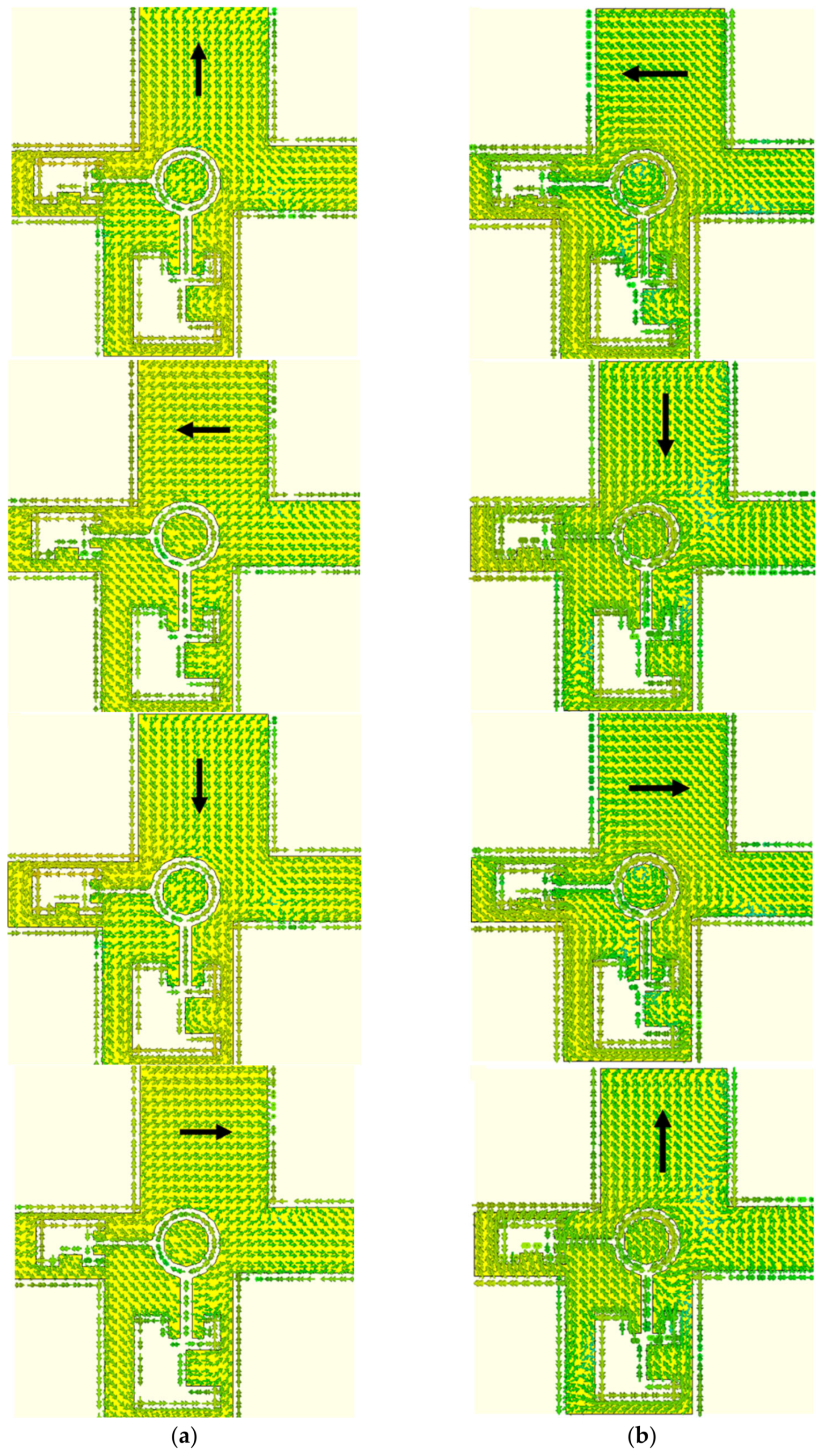
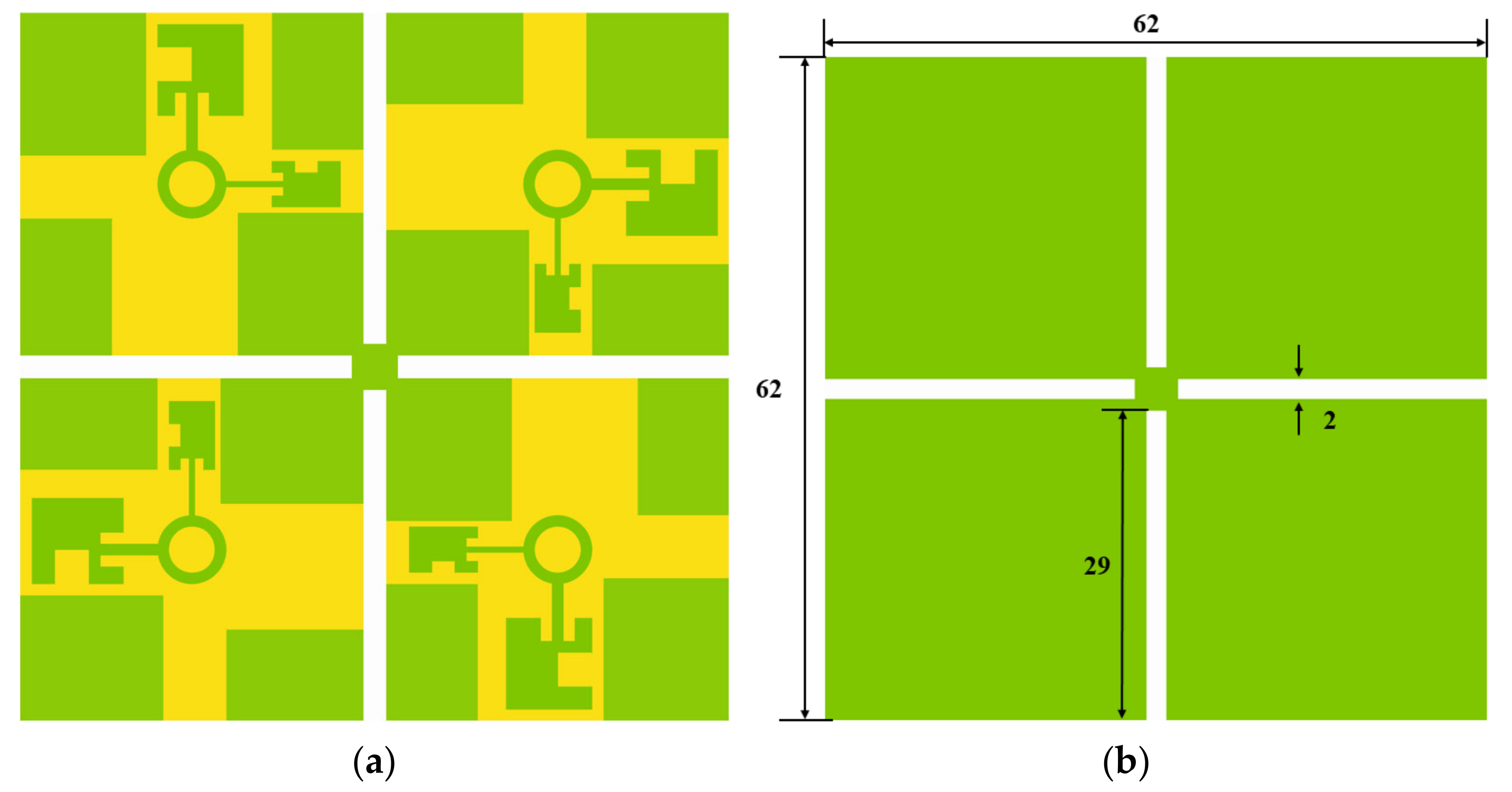
2.2. Quad-Port Antenna Design

The single-port antenna design shown in Figure 6a has undergone a significant expansion to achieve a quad-port configuration, with overall dimensions of 62 × 62 mm2. To ensure that the antenna elements remain well separated without the presence of a large gap between them, the orientation of the elements has been adjusted. In this extended MIMO configuration, all bands are effectively isolated, except for the 5 GHz band, which presented a challenge in terms of achieving the necessary isolation. To overcome this challenge, a ground slit has been incorporated on the back side of the radiating element, as depicted in Figure 6b. This modification has proven effective in enhancing isolation for all bands, resulting in a high-performing quad-element antenna design.
To assess the performance of the quad-port antenna, simulations were conducted by exciting one port and applying matched loads to the other ports. The scattering parameters were nearly identical across all antenna elements and similar to those of the single-element response. The S-parameter characteristics with and without a ground slit are depicted in Figure 7. In Figure 7, the S12 parameter measures the power transmitted from one port of the antenna to another, and it should be typically less than −20 dB for effective isolation between the ports. Case #1 represents the MIMO antenna with a full ground plane, while Case #2 features a slotted ground plane. The introduction of a ground slit did not affect the reflection behavior, as observed from S11. However, the mutual coupling between ports 1 and 4 in Case #1 at 5.15 GHz was less than 15 dB. By adding a half-wavelength ground slit, the coupling was reduced by over 8 dB from Case #1. Based on analyzing the specific resonance characteristics of the quad-port pentaband MIMO antenna, the 5 distinct frequency bands, as listed at 1.55 GHz (1.5–1.65 GHz), 2.5 GHz (2.4–2.7 GHz), 5.2 GHz (5–5.85 GHz), 7.3 GHz (7.1–7.4 GHz), and 8.15 GHz (7.9–8.4 GHz), achieve their respective mutual coupling reductions at around 27 dB, 37 dB, 21 dB, 29 dB, and 21 dB, respectively. The isolation between the antenna elements was also greater than 20 dB in all resonance bands, indicating good performance. The antenna’s overall dimensions for the quad-element design measured 62 × 62 mm2, and the orientation of the elements ensured they remained well separated without a large gap between them.
ζ i j = | S i i * S i j + S j i * S j j | 2 ( 1 ( | S i i | 2 + | S i j | 2 ) ) ( 1 ( | S j j | 2 + | S j i | 2 ) )
δ i j = | 4 π R i ( θ , ϕ ) ( θ , ϕ ) R j | 2 | 4 π ( θ , ϕ ) R i | 2 d Ω | 4 π ( θ , ϕ ) R j | 2 d Ω
The ζ i j is a correlation between antenna elements, which is denoted by R i ( θ , ϕ ) , which refers to the ith port of the radiation pattern, and the Hermitian product symbol is a dot (•). A desirable value for ECC is less than 0.5. As illustrated in Figure 8, the calculated 4-port antenna’s ECC values for all port combinations in the designated band are less than 0.05 in all resonating bands. This low-value criterion is necessary to ensure that the signal-to-noise ratio remains unaffected in a diversity scenario. This situation is also associated with the investigation of another parameter known as DG, which identifies signals traveling over multiple paths and originating from the same transmitter.
DG is defined as the ratio of the total received power from all the antennas to the received power from a single antenna. It provides insight into the effectiveness of the MIMO system in improving signal quality and reducing the effects of fading and interference. The optimal value of DG should be 10 dB. The antenna demonstrates satisfactory diversity performance, as seen in Figure 9, where Equation (3) has been employed to calculate DG [38].
D G = 10 1 | ζ i j | 2

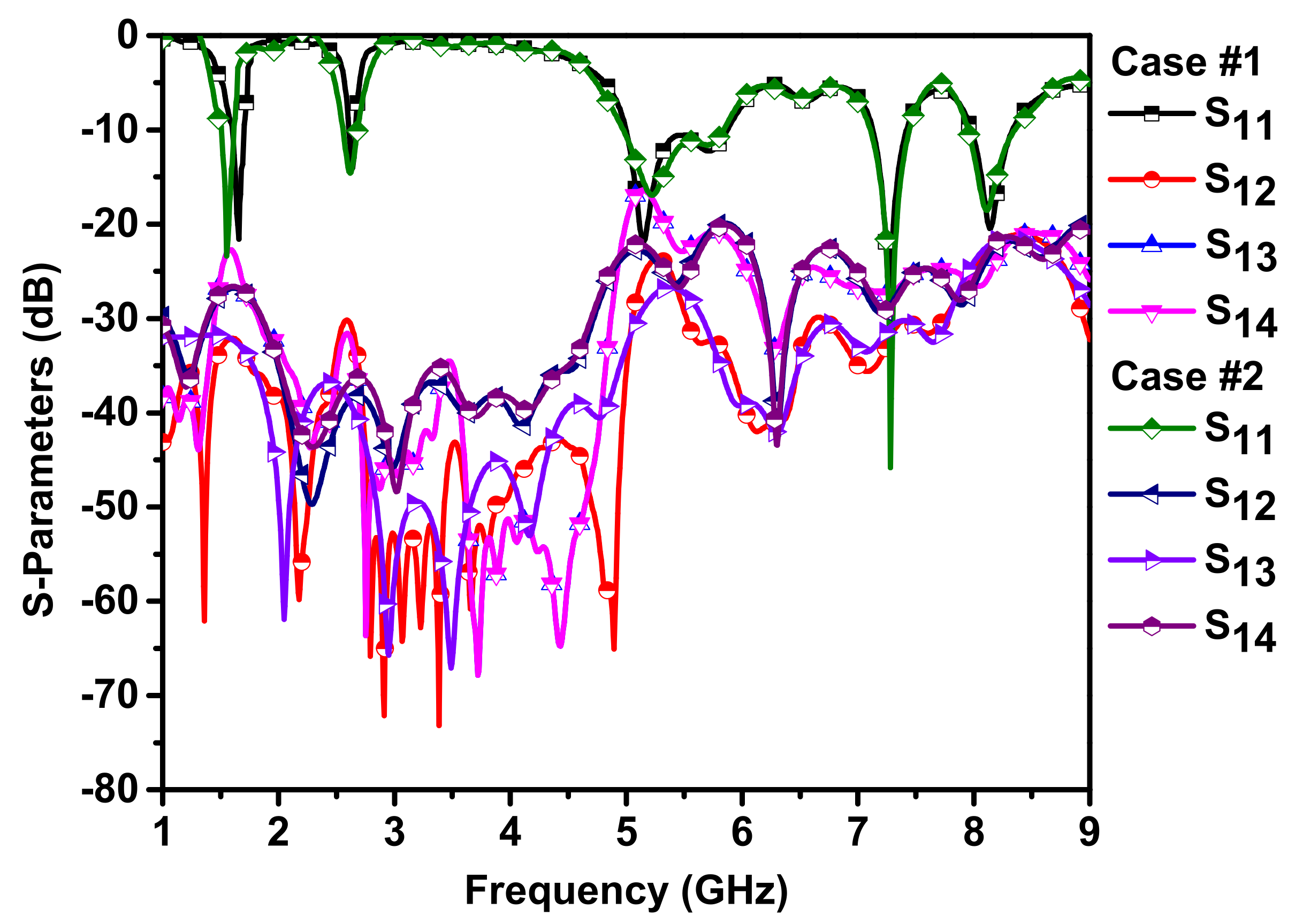
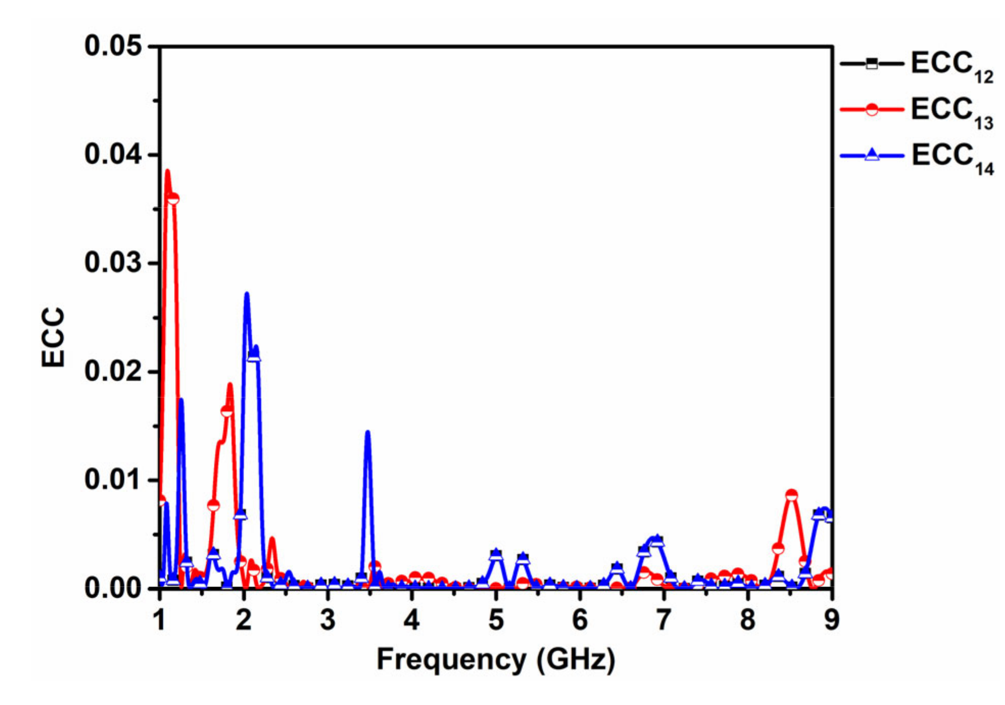
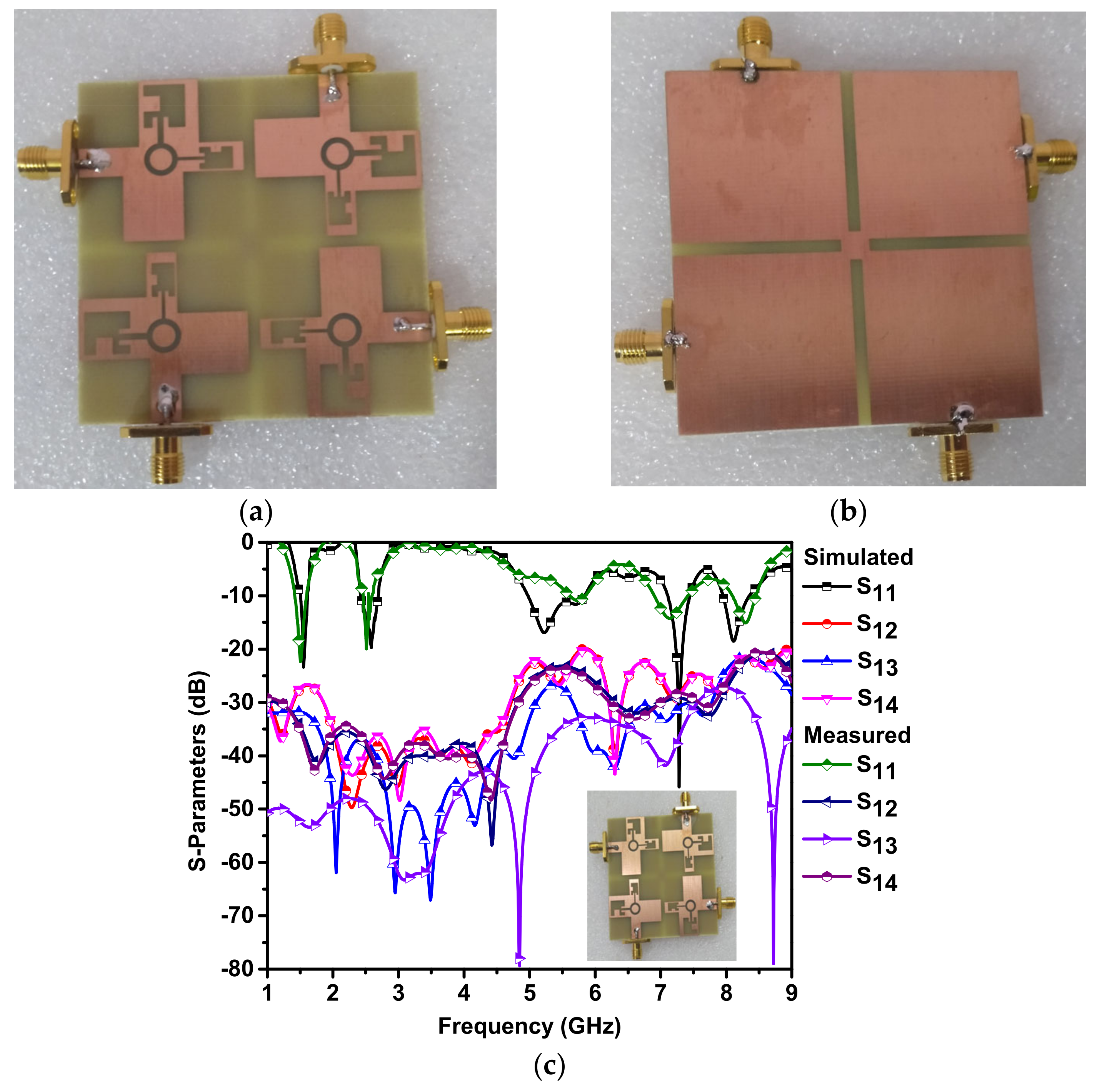
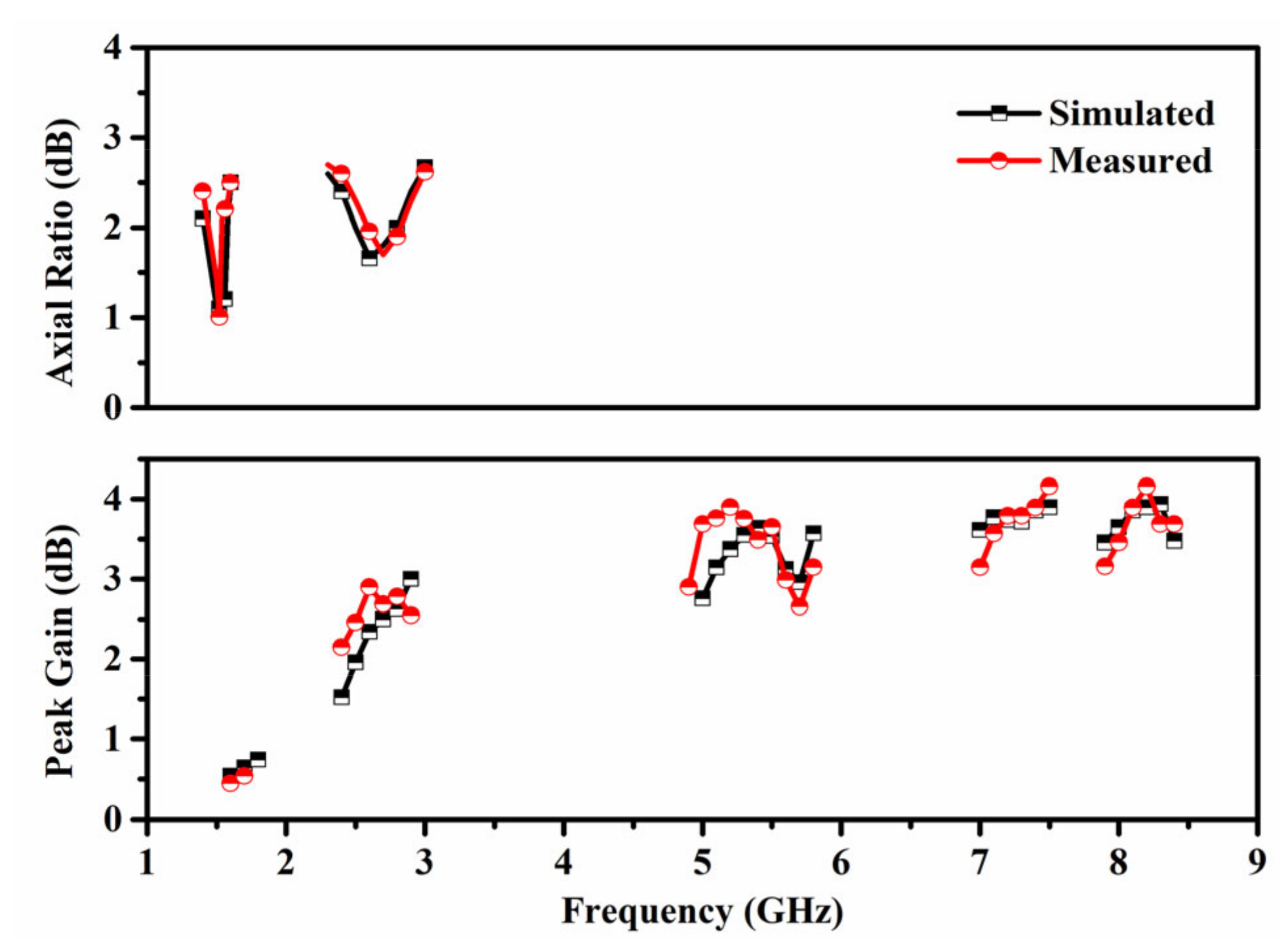
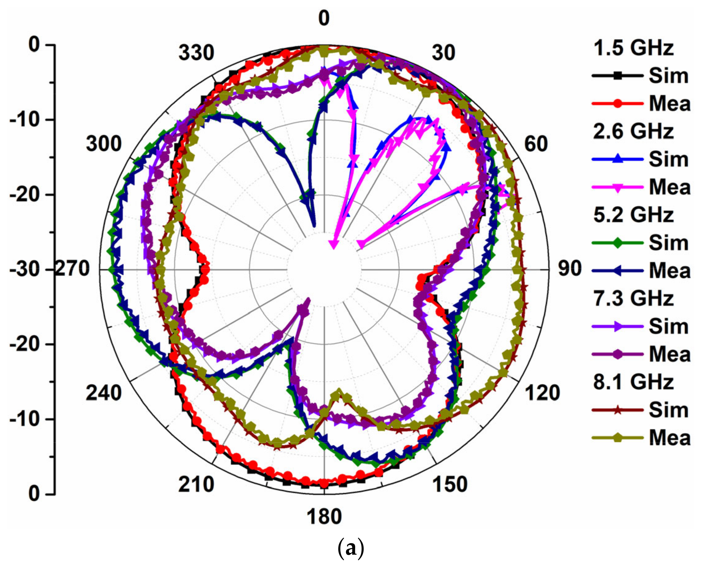
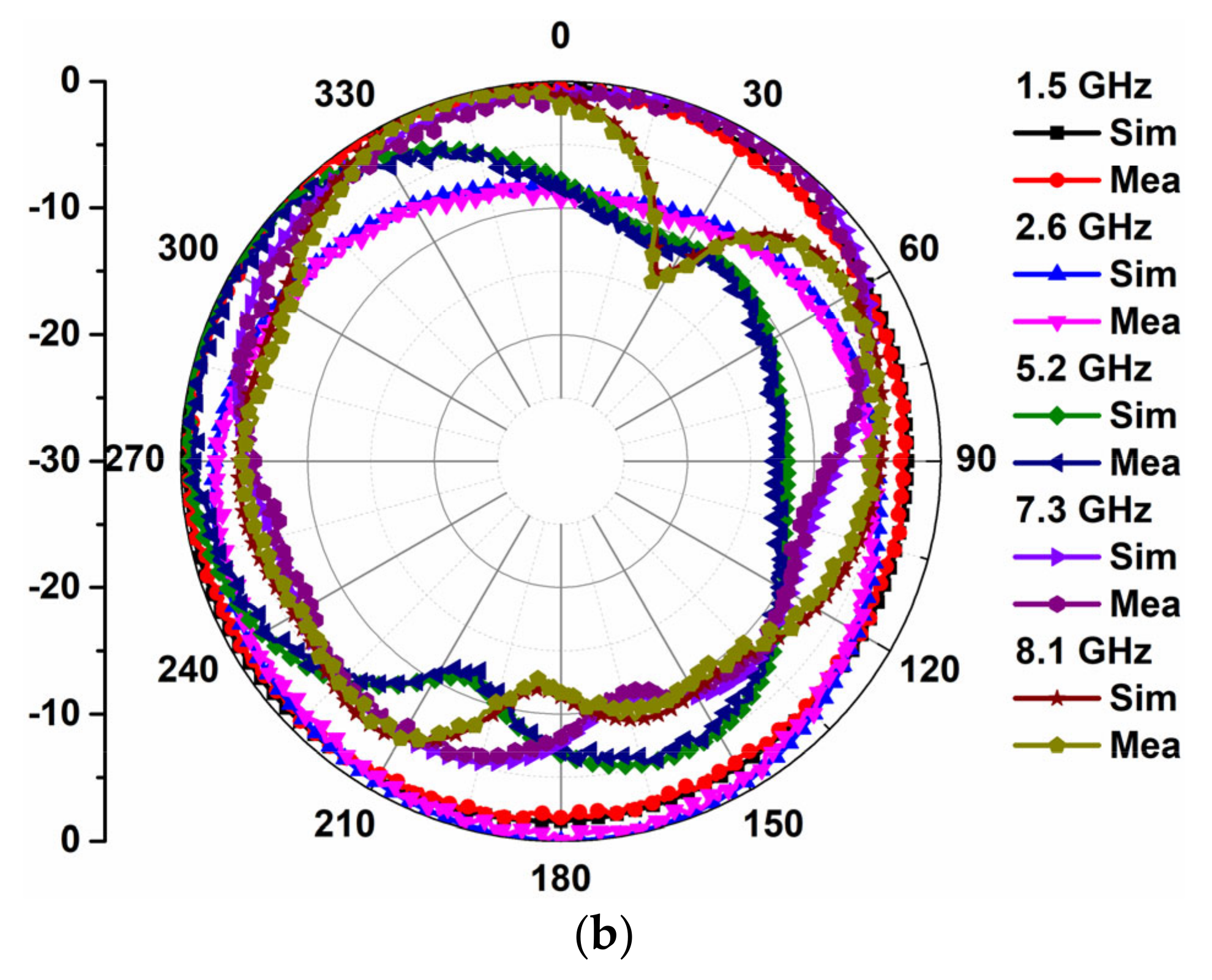
3. Experimental Validation

The MIMO antenna prototype has been fabricated on an FR-4 substrate and underwent testing. The fabricated photograph of the antenna and the simulation and measurement of S-parameters are shown in Figure 10. The S-parameter was measured using an Anritsu S820E vector network analyzer (VNA). In the measurement process for the proposed antenna, the first step involved calibration of the VNA using a standard calibration kit to ensure accurate measurements. The VNA calibration process accounted for the losses and delays associated with the cables and connectors used in the measurement setup. After calibration, the S-parameter was measured by connecting the antenna to the VNA through a coaxial cable and performing a frequency sweep from 2 GHz to 9 GHz. The measurement results were then compared with the simulated S- parameter to validate the design. The simulation predicts impedance bandwidths of 0.15 GHz, 0.3 GHz, 0.85 GHz, 0.3 GHz, and 0.5 GHz for the 5 resonance bands at 1.55 GHz, 2.5 GHz, 5.2 GHz, 7.3 GHz, and 8.15 GHz, respectively. Also, at the third resonance frequency (5.2 GHz), there are notable differences between the simulated and measured results, which could be attributed to the presence of the ground slit. Manufacturing tolerances in the ground slit’s production process could lead to variations in its width and length, resulting in changes in the electromagnetic field distribution within the structure. These changes may, in turn, impact the reflection and transmission of signals through the device, leading to discrepancies between the simulation and measurement results. Although the measured resonance bands deviate slightly from the simulation, the results indicate the feasibility of the proposed antenna for multiple-frequency bands.
The 3 dB ARBW and peak gain were also evaluated, and the simulation and measurement results are shown in Figure 11. At 1.55 GHz and 2.6 GHz, the simulated axial ratios are 1.05 and 1.65, respectively, and the measured axial ratio is in good agreement with the simulation results. Moreover, the peak gain values for the 5 resonance frequency bands are 0.55 dBi, 2.5 dBi, 3.65 dBi, 3.85 dBi, and 3.9 dBi, respectively. Furthermore, the measured gain is relatively similar to the simulated gain.
The directional properties of the MIMO antenna proposed in this paper were evaluated by measuring and simulating its radiation patterns at various frequencies. The results, as shown in Figure 12, demonstrate that the antenna exhibits bidirectional and omnidirectional patterns in both the E-plane and H-plane at lower frequencies. At higher frequencies, the E-plane pattern displays a main lobe in the +z direction, while the H-plane deviates slightly from +z and has a null at 30°. At 2.6 GHz, both the E-plane and H-plane patterns are in the -z-direction. For the other 2 frequencies, there are deviations from the +z direction, and a sharp null is observed between 0° and 30°. Overall, the directional properties of the antenna make it suitable for use in a variety of wireless applications that require reliable and consistent signal transmission and reception across multiple frequency bands.

4. Conclusions

This study introduced a novel MIMO antenna design that exhibits dual-band CP and operates in five distinct frequency bands, making it ideal for a variety of applications, including navigation, WLAN/Bluetooth, and fixed/mobile satellites. The approach of achieving multiband operation by manipulating the current distribution on the patch antenna using different configurations of slots and apertures is also discussed. A ground-plane slit is also included to enhance isolation between antenna elements at the center resonance band. The measurement process involves calibration of the vector network analyzer using a standard calibration kit and performing a frequency sweep from 2 GHz to 9 GHz. The experimental results show that the antenna has impedance bandwidths of 9.5%, 15%, 15.6%, 4%, and 6% in the pentaband, confirming the simulation results. The proposed antenna also demonstrates a maximum gain of 3.9 dBi and good diversity performance, with an ECC value below 0.004 and a DG value of 9.8 dB, which ensures that the signal-to-noise ratio is not compromised in a diversity scenario. This design has significant improvements over previous designs that have only demonstrated LP or CP in single- or dual-band MIMO antennas. These results suggest that the proposed MIMO antenna is a promising candidate for use in various wireless communication systems.

Author Contributions

Conceptualization, A.U.; methodology, A.U.; software, A.U.; validation, A.U; investigation, V.A.; resources, V.A.; data curation, V.A.; writing—original draft preparation, A.U.; writing—review and editing, A.U.; visualization, A.U.; supervision, V.A.; project administration, V.A.; funding acquisition, A.U. All authors have read and agreed to the published version of the manuscript.

Funding

This research received no external funding.

Data Availability Statement

No data availability statement.

Conflicts of Interest

The authors declare no conflict of interest.

References

  1. Lee, Y.C.; Sun, J.S. A New Printed Antenna for Multiband Wireless Applications. IEEE Antennas Wirel. Propag. Lett. 2008, 8, 402–405. [Google Scholar]
  2. Kumar, R.; Kamatham, Y.; Peddakrishna, S.; Gaddam, A. CPW-Fed Penta Band Monopole Antenna for Multiservice Wireless Applications. Adv. Technol. Innov. 2021, 1, 66–76. [Google Scholar] [CrossRef]
  3. Huang, H.; Liu, Y.; Zhang, S.; Gong, S. Multiband Metamaterial-Loaded Monopole Antenna for WLAN/WiMAX Applications. IEEE Antennas Wirel. Propag. Lett. 2014, 14, 662–665. [Google Scholar] [CrossRef]
  4. Kollipara, V.; Peddakrishna, S.; Kumar, J. Planar EBG Loaded UWB Monopole Antenna with Triple Notch Characteristics. Int. J. Eng. Technol. Innov. 2021, 11, 294–304. [Google Scholar] [CrossRef]
  5. Yang, L.; Li, T.; Yan, S. Highly Compact MIMO Antenna System for LTE/ISM Applications. Int. J. Antennas. Propag. 2015, 2015, 1–10. [Google Scholar] [CrossRef]
  6. Papamichael, V.C.; Karadimas, P. Performance Evaluation of Actual Multielement Antenna Systems under Transmit Antenna Selection/Maximal Ratio Combining. IEEE Antennas Wirel. Propag. Lett. 2011, 10, 690–692. [Google Scholar] [CrossRef]
  7. Sanayei, S.; Nosratinia, A. Antenna Selection in MIMO Systems. IEEE Commun. Mag. 2004, 42, 68–73. [Google Scholar] [CrossRef]
  8. Ehrenborg, C.; Gustafsson, M. Fundamental bounds on MIMO antennas. IEEE Antennas Wirel. Propag. Lett. 2017, 17, 21–24. [Google Scholar] [CrossRef]
  9. Pouyanfar, N.; Ghobadi, C.; Nourinia, J.; Pedram, K.; Majidzadeh, M. A compact multi-band MIMO antenna with high isolation for C and X bands using defected ground structure. Radio Eng. 2018, 27, 686–693. [Google Scholar] [CrossRef]
  10. Kollipara, V.; Peddakrishna, S. Quad-Port Circularly Polarized MIMO Antenna with Wide Axial Ratio. Sensors 2022, 22, 7972. [Google Scholar] [CrossRef]
  11. Zhang, S.; Chen, X.; Pedersen, G.F. Mutual coupling suppression with decoupling ground for massive MIMO antenna arrays. IEEE Trans. Veh. Technol. 2019, 68, 7273–7282. [Google Scholar] [CrossRef]
  12. Nadeem, I.; Choi, D.Y. Study on mutual coupling reduction technique for MIMO antennas. IEEE Access 2018, 7, 563–586. [Google Scholar] [CrossRef]
  13. Chiu, C.Y.; Xu, F.; Shen, S.; Murch, R.D. Mutual coupling reduction of rotationally symmetric multiport antennas. IEEE Trans. Antennas Propag. 2018, 66, 5013–5021. [Google Scholar] [CrossRef]
  14. Zhang, S.; Pedersen, G.F. Mutual coupling reduction for UWB MIMO antennas with a wideband neutralization line. IEEE Antennas Wirel. Propag. Lett. 2015, 15, 166–169. [Google Scholar] [CrossRef]
  15. Kayabasi, A.; Toktas, A.; Yigit, E.; Sabanci, K. Triangular Quad-Port Multi-Polarized UWB MIMO Antenna with Enhanced Isolation Using Neutralization Ring. AEU Int. J. Electron. Commun. 2018, 85, 47–53. [Google Scholar] [CrossRef]
  16. Maddio, S.; Pelosi, G.; Righini, M.; Selleri, S.; Vecchi, I. Mutual Coupling Reduction in Multilayer Patch Antennas via Meander Line Parasites. Electron. Lett. 2018, 54, 922–924. [Google Scholar] [CrossRef]
  17. Hassan, T.; Khan, M.U.; Attia, H.; Sharawi, M.S. An FSS Based Correlation Reduction Technique for MIMO Antennas. IEEE Trans. Antennas Propag. 2018, 66, 4900–4905. [Google Scholar] [CrossRef]
  18. Wang, Z.; Zhao, L.; Cai, Y.; Zheng, S.; Yin, Y. A Meta-Surface Antenna Array Decoupling (MAAD) Method for Mutual Coupling Reduction in a MIMO Antenna System. Sci. Rep. 2018, 8, 3152. [Google Scholar] [CrossRef]
  19. Wu, W.; Zhi, R.; Chen, Y.; Li, H.; Tan, Y.; Liu, G. A Compact Multiband MIMO Antenna for IEEE 802.11 a/b/g/n Applications. Prog. Electromagn. Res. Lett. 2019, 84, 59–65. [Google Scholar] [CrossRef]
  20. Chaudhari, A.A.; Gupta, R.K. A Simple Tri-Band MIMO Antenna Using a Single Ground Stub. Prog. Electromagn. Res. C 2018, 86, 191–201. [Google Scholar] [CrossRef]
  21. Rao, P.S.; Kamili, J.B.; Prasad, A.M. Compact Multi-Band MIMO Antenna with Improved Isolation. Prog. Electromagn. Res. M 2017, 62, 199–210. [Google Scholar]
  22. Fakharian, M.M.; Alibakhshikenari, M.; See, C.H.; Abd-Alhameed, R. A High Gain Multiband Offset MIMO Antenna Based on a Planar Log-Periodic Array for Ku/K-Band Applications. Sci. Rep. 2022, 12, 4044. [Google Scholar] [CrossRef]
  23. Nezhad, S.M.A.; Hassani, H. Penta-Band Printed Monopole Antenna for MIMO Applications. Prog. Electromagn. Res. C 2018, 84, 241–254. [Google Scholar] [CrossRef]
  24. Krishnamoorthy, R.; Desai, A.; Patel, R.; Grover, A. 4-Element Compact Triple Band MIMO Antenna for Sub-6 GHz 5G Wireless Applications. Wirel. Netw. 2021, 27, 3747–3759. [Google Scholar] [CrossRef]
  25. Ojaroudi, P.N.; Jahanbakhsh, B.H.; Al-Yasir, Y.I.; Ullah, A.; Abd-Alhameed, R.A.; Noras, J.M. Multi-Band MIMO Antenna Design with User-Impact Investigation for 4G and 5G Mobile Terminals. Sensors 2019, 19, 456. [Google Scholar] [CrossRef]
  26. Naidu, P.V.; Saiharanadh, A.; Maheshbabu, D.; Kumar, A.; Vummadisetty, N. Design and Performance Analysis of G-Shaped Compact ACS Fed 4-Port MIMO Antenna for Triple Frequency Band Applications. Prog. Electromagn. Res. C 2021, 112, 55–68. [Google Scholar] [CrossRef]
  27. Ikram, M.; Nguyen-Trong, N.; Abbosh, A. Multiband MIMO Microwave and Millimeter Antenna System Employing Dual-Function Tapered Slot Structure. IEEE Trans. Antennas Propag. 2019, 67, 5705–5710. [Google Scholar] [CrossRef]
  28. Nej, S.; Ghosh, A.; Ahmad, S.; Ghaffar, A.; Hussein, M. Compact Quad Band MIMO Antenna Design with Enhanced Gain for Wireless Communications. Sensors 2022, 22, 7143. [Google Scholar] [CrossRef]
  29. Sharma, D.; Kanaujia, B.K.; Kumar, S. Compact Multi-Standard Planar MIMO Antenna for IoT/WLAN/Sub-6 GHz/X-Band Applications. Wirel. Netw. 2021, 27, 2671–2689. [Google Scholar] [CrossRef]
  30. Wen, H.; Qi, Y.; Weng, Z.; Li, F.; Fan, J. A Multiband Dual-Polarized Omnidirectional Antenna for 2G/3G/LTE Applications. IEEE Antennas Wirel. Propag. Lett. 2017, 17, 180–183. [Google Scholar] [CrossRef]
  31. Kumar, S.; Lee, G.H.; Kim, D.H.; Choi, H.C.; Kim, K.W. Dual circularly polarized planar four-port MIMO antenna with wide axial-ratio bandwidth. Sensors 2020, 20, 5610. [Google Scholar] [CrossRef]
  32. Jamal, M.Y.; Li, M.; Yeung, K.L. Isolation enhancement of closely packed dual circularly polarized MIMO antenna using hybrid technique. IEEE Access 2020, 8, 11241–11247. [Google Scholar] [CrossRef]
  33. Parbat, R.S.; Tambe, A.R.; Kadu, M.B.; Labade, R.P. Dual polarized triple band 4 × 4 MIMO antenna with novel mutual coupling reduction approach. In Proceedings of the 2015 IEEE Bombay Section Symposium (IBSS), Mumbai, India, 10–11 September 2015; pp. 1–6. [Google Scholar]
  34. Mohanty, A.; Behera, B.R. CMA assisted 4-port compact MIMO antenna with dual-polarization characteristics. AEU Int. J. Electron. Commun. 2021, 137, 153794. [Google Scholar] [CrossRef]
  35. Saxena, G.; Awasthi, Y.K.; Jain, P. Four-element pentaband MIMO antenna for multiple wireless applications including dual-band circular polarization characteristics. Int. J. Microw. Wirel. Technol. 2022, 14, 465–476. [Google Scholar] [CrossRef]
  36. Blanch, S.; Romeu, J.; Corbella, I. Exact representation of antenna system diversity performance from input parameter description. Electron. Lett. 2003, 39, 705–707. [Google Scholar] [CrossRef]
  37. Hallbjorner, P. The significance of radiation efficiencies when using S-parameters to calculate the received signal correlation from two antennas. IEEE Antennas Wirel. Propag. Lett. 2005, 4, 97–99. [Google Scholar] [CrossRef]
  38. Schwartz, M.; Bennett, W.R.; Stein, S. Communication Systems and Techniques; McGraw-Hill: New York, NY, USA, 1966. [Google Scholar]
Figure 1. Systematic representation of the design process.
Computation 11 00076 g001
Figure 2. Single-port pentaband antenna geometry.
Computation 11 00076 g002
Figure 3. Step-wise design procedure for achieving multiband operation. (a) Ant #1, (b) Ant #2, (c) Ant #3, and (d) Ant #4.
Computation 11 00076 g003
Figure 4. Single element pentaband reflection coefficient of Ants #1 to #4. (a) Reflection coefficient (b) axial ratio.
Computation 11 00076 g004
Figure 5. Surface current distribution of proposed antenna at 1.5 GHz and 2.6 GHz. (a) 1.5 GHz, (b) 2.6 GHz.
Computation 11 00076 g005
Figure 6. Quad-port pentaband antenna, (a) top and (b) bottom.
Computation 11 00076 g006
Figure 7. Pentaband MIMO antenna S-parameters comparison with and without a ground plane. In order to evaluate the diversity performance of the MIMO antenna, several parameters are considered, including ECC and DG. ECC can be calculated using either the covariance matrix or the correlation coefficient matrix. The covariance matrix represents the covariance between the received signals at different antenna elements, whereas the correlation coefficient matrix represents the correlation coefficient between the received signals. The correlation coefficient is normalized to values between −1 and 1 and can be obtained by dividing the covariance matrix by the product of the standard deviations of the signals received by the antennas. In the context of wireless applications, ECC is a critical diversity parameter that can provide insights into the correlation between antennas. Essentially, ECC quantifies the interaction among the antenna elements using either Equation (1) or Equation (2) [36,37].
Computation 11 00076 g007
Figure 8. ECC of the quad-port antenna.
Computation 11 00076 g008
Figure 9. DG of the quad-port antenna.
Computation 11 00076 g009
Figure 10. Fabricated prototype and S-parameter validation comparison. (a) Top, (b) bottom, and (c) simulated and measured S-parameter comparison.
Computation 11 00076 g010
Figure 11. Quad-port antenna simulated axial ratio and gain comparison with measured results.
Computation 11 00076 g011
Figure 12. Simulated and measured radiation pattern comparison. (a) E-Plane and (b) H-plane.
Computation 11 00076 g012aComputation 11 00076 g012b
Table 1. Comparison of pentaband MIMO antenna with the antennas in the literature.
RefAntenna Dimensions
w × l × h
(mm3)
Operating Bands
(GHz)
No. of PortsPolarization
(LP/CP)
Isolation
(dB)
[19]50 × 30 × 1.59Dual2LP24,27
[20]38 × 37 × 1.6Triple2LP20
[21]64 × 35 × 1.6Multi2LP32.79
[22]55 × 45 × 1.57Quad2LP23.5
[23]29.5 × 27 × 0.8Penta2LP16
[24]-- × -- × 1.6Triple4LP16
[25]150 × 75 × 1.6Triple4LP17
[26]46 × 46 × 1.6Triple4LP18
[27]104 × 104 × 0.5Triple8LP16
[28]80 × 70 × 1.6Quad4LP22
[29]117 × 65 × 0.762Penta6LP14.5
[33]165 × 165 × 1.6Triple4CP41
[34]60 × 60 × 1.6Triple4Dual15
[35]50 × 70 × 0.762Penta4Dual17
Prop.
work
62 × 62 × 1.6Penta4Dual21
Table 2. Geometrical parameters of the single-port antenna.
ParameterWsLsWpLpWp1Lp1abg
Value (mm)303012.511128460.5
Parametercdg1WsLsWs1Ls1rinrout
Value (mm)87.51123323
Disclaimer/Publisher’s Note: The statements, opinions and data contained in all publications are solely those of the individual author(s) and contributor(s) and not of MDPI and/or the editor(s). MDPI and/or the editor(s) disclaim responsibility for any injury to people or property resulting from any ideas, methods, instructions or products referred to in the content.

