Abstract
Waste heat recovery is one of the main practices used to reduce the carbon footprint of the industrial sector regarding environmental concern. The supercritical carbon dioxide (s-CO2) cycle is one of the most attractive heat-to-power technologies; due to the abrupt variation in CO2 properties in the vicinity of its critical point, small compression work is required and finally a high cycle efficiency is achieved. In the literature, among the various proposed layouts, the recompression s-CO2 Brayton cycle is considered to be the most efficient one. The most critical component of such a cycle is definitely the main compressor, as the related usual design procedures have been developed in the past for ideal gas as a working fluid. This study presents a methodology for the preliminary design of a centrifugal compressor with a vaned diffuser, suitable for fulfilling the desired operating requirements of a particular supercritical CO2 recompression Brayton cycle. Furthermore, it demonstrates the numerical investigation of the three-dimensional (3D) flow phenomena occurring in it, focusing on the investigation of possible condensation. To this end, a one-dimensional flow model was developed to provide information regarding the geometry of the compressor and predict its prospective performance. Commercial computational fluid dynamics (CFD) software was then employed to examine the three-dimensional flow. The effect of accuracy in the evaluation of real gas properties approaching the critical point was examined, showing that a look-up table with more points around the critical point can reduce the numerical relative error by up to 0.3% for the value of specific heat capacity. In addition, the possibility of condensation occurrence was investigated at the impeller’s inlet, where the flow is accelerated. The supersaturation pressure ratio was defined and implemented in order to identify regions where static pressure is lower than saturation pressure, possibly leading to local two-phase flow.
1. Introduction
During the last few decades, the world has been transforming from coal burning to clean energy, adopting cleaner, reliable and more efficient power systems. Supercritical carbon dioxide (s-CO2) Brayton cycles constitute a promising power conversion technology that exploits waste heat recovery, converting the heat received by a thermal source to electricity.
Such cycles have increasingly attracted research interest during the last few years because of the efficiencies that they achieve (up to 50%), especially for turbine inlet temperatures over 500 °C. These closed-loop Brayton cycles take advantage of the abrupt variation in CO2 properties near their critical point (304.13 K, 7.38 MPa) (Figure 1), resulting in a reduction in compression work and finally a more efficient system. The supercritical carbon dioxide cycles for power generation were first proposed by Feher [1], while, in 1969, Angelino [2] examined different configurations of s-CO2 cycles, providing performance results for each layout, and concluded that the thermal efficiency of the recompression cycle can be comparable with that of a Rankine cycle. Lately, the s-CO2 Brayton cycle has regained the attention of the research community as CO2 is free of regulations for non-eco-friendly working fluids, constituting one of the state-of-the-art power conversion cycles. The interest for supercritical CO2 Brayton cycles was revived at the dawn of the 2000s, when Dostal et al. [3] studied an s-CO2 Brayton cycle as an alternative for the cooling of a nuclear reactor. Since then, the majority of research studies on s-CO2 Brayton cycles concern cycle operation simulation and the design of cycle components.
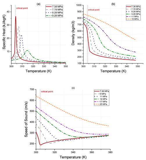
Figure 1.
Carbon dioxide’s (a) specific heat, (b) density, and (c) speed of sound as a function of temperature.
As a result of the aforementioned advantages, there is continuously growing research on s-CO2 power cycles, focusing on the design optimization of critical components, such as the involved turbomachinery and heat exchangers, as well as improvements in the thermodynamic cycle toward the commercialization of this technology [4]. The compressor constitutes one of the most critical components of the cycle. Developing a compressor that can stably work over a wide operational range helps us to ensure a robust operation of the whole engine. Supercritical carbon dioxide power cycles demand high compressor efficiencies at design and off-design operating points, as variations in the aerodynamic performance of the compressor may significantly affect the whole cycle performance and control; this is due to the aforementioned abrupt variation in the working fluid properties near the critical point and the subsequent risk for two-phase flow. Therefore, the design and performance prediction of a compressor operating with supercritical CO2 is one of the most significant challenges for the commercialization of this power generation technology. At this moment, there are no established power plants operating with supercritical CO2. Nevertheless, some small test rigs, such as those in SANDIA NL in USA, Institute of Applied Energy in Japan, Korea Advanced Science and Technology in South Korea and Brunel University in UK [5], have been developed in order to examine the operating technology, employing different types of turbomachinery, such as the screw or dynamic type. Ahn et al. [6] presented a design consideration for one of the first experimental loops, while Bae et al. [7] presented an analysis of the operation of the same test rig close to the critical point. Moreover, much research has been focused on the effect of critical components on the whole system performance, such as the compressor [8,9] and the heat exchangers [10].
Although significant progress has been made in the design of turbomachinery operating with conventional gases behaving as ideal ones, only recently has the research interest focused on high-density or supercritical fluids, where the ideal gas assumption does not hold. The sharp variation in thermodynamic properties of CO2 in a region around the critical point, where the compressors operate, demands careful design to ensure a safe operation and high-efficiency performance. Though one-dimensional models are commonly used for the design of compressors, a detailed CFD model can predict the aerodynamics of the flow field much better and provide significant information to improve the compressor performance. For example, Yao et al. [11] proposed a one-dimensional design methodology and investigated how it can be applied to 500 kWe and 5 MWe recompression cycles, concluding that a higher mass flow rate would lead to a higher turbomachinery efficiency in the 5 MWe cycle and that the reduction stator loss contributes to an improvement in the turbomachinery efficiency. Moreover, Liu et al. [12] presented a study concerning the preliminary design of axial and centrifugal compressors and validated the results of their design against CFD simulations.
An important issue that may be faced in a supercritical CO2 compression system is the possible occurrence of condensation due to the vicinity of the working fluid states at the compressor inlet with the critical point of CO2. While most s-CO2 compressors are designed to operate as single-phase machines, when approaching the critical point of CO2, it becomes difficult to clearly distinguish if the behavior of the fluid is closer to that of a compressible or incompressible gas. In order to avoid the possibility of two-phase flow, which may occur at the impeller’s leading-edge region where the velocity of the flow increases (in terms of absolute velocity), the thermodynamic conditions at the entry of the compressor are usually slipped away from the critical point on purpose. As a consequence, the required compression work increases and, subsequently, the s-CO2 cycle efficiency is reduced.
There are not many investigations concerning the design of turbomachines with fluids working close to their critical points. Most such studies rely on the use of one-dimensional flow models, incorporating real gas effects, in order to predict the possibility of condensation whenever in the vicinity of a critical point. Firstly, at the Sandia NL test facility, the performance of a centrifugal compressor using supercritical CO2 operating near its critical point was presented by Wright et al. [13], and it was found that any potential effects from the two-phase flow may not have a significant impact on the compressor. Monge [14] conducted research on the factors that may result in condensation during compressor operation, proposing an upper limit for flow acceleration. Pecnik et al. [15] examined the possibility of two-phase flow taking place in the impeller of a centrifugal compressor that operates near the critical point of CO2 by handling the possible condensation of the fluid as being in the equilibrium condition. De Lorenzo et al. [16] also employed the homogeneous equilibrium model and achieved successfully simulating the two-phase water–steam flow under transient conditions. Moreover, a study was presented by Baltadjiev et al. [17] taking into account the properties variation in the fluid in the metastable region and the condensation when the flow is under conditions out of equilibrium, also proposing a criterion for condensation occurrence.
Real gas effects near the critical point were investigated by Ameli et al. [18], examining the accuracy of the relevant property tables that were constructed for their numerical models, as well as how two-phase flow is created at the impeller leading edge. More recently, Guo et al. [19] investigated the influence of real gas properties of supercritical CO2 on the one-dimensional isentropic compression process. A study presented by Saravi et al. [20] focused on the aerodynamics of the compressor diffuser, taking into account the real gas effects in order to achieve the compressor target operating conditions and improve its performance in the supercritical region. Lately, Lettieri et al. [21] presented a study about models concerning equations of state (EOSs) and how they can predict the condensation in supercritical compressors. In the past decades, several equation-of-state models have been examined, achieving different accuracy levels that depend on the range of thermodynamic states of interest for CO2. Lüdtke [22] presented a study comparing various common real gas models and exhibiting a deviation from experimental data of less than 2%. However, the Span–Wagner (SW) model [23], being developed in 1996 particularly for carbon dioxide, is considered nowadays, according to the literature, to be the most widespread and accurate model for estimating the properties of CO2. This is an EOS model developed for real gases, expressed in terms of Helmholtz energy, and covering the states contained in the range from the triple point to the state corresponding to a temperature of 1100 K and a pressure of 80 MPa. Baltadjiev et al. [17] also compared the various EOS models, focusing on the region around the critical point, indicating that they all present an acceptable accuracy in the case of a compressor operating in the supercritical CO2 region; however, simulating the operation closer to the critical point, the SW model was claimed as the most well-proposed. Finally, Zhao et al. [24] presented a selection procedure for EOS and how it can affect the design of the compressor and its operational performance.
In light of the above, the main goal of this paper is to present a methodology for the preliminary design of a centrifugal compressor with a vaned diffuser, suitable for fulfilling the desired operating requirements of a particular supercritical CO2 recompression Brayton cycle and demonstrating the subsequent numerical investigation of the three-dimensional (3D) flow phenomena occurring in it. The preliminary design relies on the use of an in-house one-dimensional (1D) tool, while commercial CFD software was implemented for the numerical simulation of the full 3D flow through the compressor. Since, according to the thermodynamic cycle, the compressor inlet conditions are close to the critical state of CO2, the possibility of local condensation and the subsequent occurrence of two-phase flow was investigated at the region of the impeller leading edge, where the absolute flow is accelerated. The real gas approximation was considered, examining how this affects the numerical prediction of the compressor performance, as well as the possibility of condensation. In particular, the effect of real gas properties in the pseudo-critical region on the accuracy of the numerical solution was studied with respect to the grid density of the tabulated data close to the critical point. This study may be used as a guide to evaluate the compressor performance for the desired inlet and outlet conditions and to examine the possibility of redesigning the blade angle of the leading edge in order to avoid the possibility of condensation and improve the compressor efficiency. In this context, the present work consists of the first step of the authors toward the direction of performing, in the long-term, in-depth research on the state-of-the-art topic of compressor design optimization suitable for the supercritical carbon dioxide cycle.
2. Design Methodology
Figure 2 presents the layout of a supercritical CO2 closed-loop Brayton cycle with recompression [25] and the corresponding temperature–entropy diagram. The main compressor that was under consideration in the present study was a single-stage centrifugal compressor (denoted by C1 in Figure 2), and is one of the most critical components of such a cycle. The process of recompression improves cycle efficiency; to this end, a second compressor was implemented (named re-compressor and denoted by C2 in Figure 2). In this cycle, the flow is split into two parts before entering the pre-cooler; one of the two parts is compressed in the second compressor C2 without entering the pre-cooler in order to overcome the pinch-point problem. The latter is concerned with the fact that the temperature gradient does not ensure a stable heat transfer between the two sides of the CO2 (hot and cold), mainly for the low-temperature recuperator (LTR). The two flows (coming from the LTR and C2) are then mixed and the total flow is driven to the high-temperature recuperator (HTR) in order to be further heated before the whole fluid enters the heater. The superheated CO2 exiting the turbine is cooled down in two stages: firstly at the HTR and then at the LTR. After preheating is completed, the flow is split into two flows: the main part of it continues to the precooler (state 8a in Figure 2) and then to the main compressor C1, whereas the smaller part of the working fluid flows to the re-compressor C2 (8b in Figure 2).
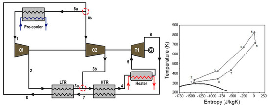
Figure 2.
Layout of the recompression s-CO2 Brayton cycle.
This s-CO2 Brayton cycle was designed for a net power production of approximately 122 MWth, with a turbine inlet temperature of 550 °C and a high cycle pressure of 20 MPa. For the thermodynamic design of the cycle, the turbomachinery components were considered to operate with an isentropic efficiency equal to 80% for the two compressors (main compressor C1 and re-compressor C2), and 90% for the turbine (T1). The total mass CO2 flowrate of the cycle is 620 kg/s; 60% of it flows through the large compressor (C1), whereas the remaining 40% is driven through the second compressor C2 (the split ratio is 0.6). The design parameters of this cycle are summarized in Table 1.

Table 1.
Specifications used for the recompression s-CO2 Brayton cycle.
The main compressor (C1) was selected to be of radial design due to its higher pressure rise per stage, the lower volume flow and wider operational range used to perform a variation in the properties of the supercritical carbon for the operation near the critical state of CO2. A fully developed one-dimensional design tool was employed to simulate the centrifugal compressor’s operation, combining performance parameters and pressure loss coefficients based on correlations by the literature. The design process consisted of two parts, corresponding to the solution of a direct problem first and then of an inverse problem, as was proposed by Monge [14]. The direct problem was set up for a centrifugal compressor used by SNL with known geometric characteristics. Its solution, in terms of predicted conditions at the compressor’s exit, was validated against Sandia’s results [13], as presented in Table 2. Hence, for the inverse problem, the same equations were used in a different way to estimate the geometric parameters based on the specified thermodynamic quantities of the cycle. The preliminary design method proposed by Balje [26] provides estimations for design parameters, employing the specific speed Ns and the specific diameter Ds to define some basic flow and geometric characteristics to reach a maximum efficiency (Equations (1) and (2) below), namely the number of stages, rotational speed, impeller diameter and stage efficiency. The values of the design parameters for the main centrifugal compressor of the cycle were selected to result in a specific speed (Ns) and specific diameter (Ds) with values of approximately 0.6 and 4, respectively, which lead to a high efficiency of the centrifugal compressor. The thermodynamic conditions, such as the density and specific enthalpy difference, that are used to define the tip diameter of the compressor and the rotational speed come from the thermodynamic analysis of the preceded cycle. The estimated design parameters of the compressor are presented in Table 3.

Table 2.
Design parameters for the recompression s-CO2 Brayton cycle.

Table 3.
Centrifugal compressor’s design parameters.
All of the parameters of Table 3 were used as the input to the design model of the compressor; the latter was built as an in-house code. Afterwards, the velocity triangles and blade geometry were defined based on the geometry design input (impeller diameter and length). The flow quantities and main dimensions were evaluated at each sub-system of the compressor depicted in Figure 3. The flow was considered to be axial and uniform at the inlet of the impeller, since no inlet guides exist. At the exit of the impeller, the slip factor was estimated based on the Wiesner expression [27], while the diffuser was considered to have vanes with a wedge shape.
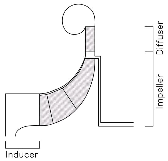
Figure 3.
Meridional view of a centrifugal compressor stage.
Finally, the design process takes into consideration the pressure losses in the compressor components, as they are calculated by loss models that update the initial assumed value of efficiency (from Balje diagram) until convergence. The results of this preliminary design methodology are presented in Table 4 for both the impeller and diffuser of the compressor, summarizing the geometrical characteristics of the main compressor. The shrouded impeller includes eleven main blades and eleven splitter blades, while the diffuser has 19 wedge-shaped vanes.

Table 4.
Geometry of the designed compressor.
The loss models considered for the performance prediction of the compressor were classified into internal and external ones [28] and are shown in Table 5. In particular, the generated irreversibilities of the fluid flowing through the impeller’s passage were modeled using internal loss models, whereas the non-isentropic losses occurring outside the impeller were modeled using the external (parasitic) losses. The solution of the inverse problem begins with the estimation of the mean diameter. Next, a hub-to-tip ratio is assumed; here, the hub-to-tip ratio at the inlet was considered to be equal to 0.4 in order to avoid a static inlet pressure in the two-phase zone. The velocity triangles were estimated at the exit of the inducer and the pressure loss at the exit of the inducer was estimated, and the other conditions were subsequently estimated. These conditions are supposed to be the inlet for the impeller, where efficiency is assumed. From the velocity triangles, the efficiency was estimated at the outlet of the impeller, and the process was repeated until the convergence of the assumed and calculated values of efficiency.

Table 5.
Formulas used to estimate pressure loss mechanisms for centrifugal compressor design and related references.
The procedure then continued to the next components of the compressor. This procedure was repeated until convergence in the stage efficiency. The flowchart of the design procedure is shown in Figure 4.
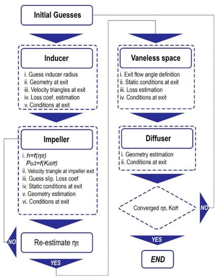
Figure 4.
One-dimensional mean-line design methodology.
3. Set-Up of the CFD Model
3.1. Geometry and Mesh
Based on the preliminary design of the compressor flow path by means of the 1D model, the final 3D geometry of the compressor was produced by employing the commercial blade modeler software BladeGen [32], which allows us to create and modify appropriately different types of turbomachinery. The design of the compressor was divided into two separate models: one for the impeller and the other for the diffuser. Both models were then assembled to simulate the operation of the whole compressor.
For the mesh generation, the commercial software TurboGrid [33] was used, implementing a finer mesh near the blade surface and a coarser one toward the center of the flow. Automatic topology and meshing methods were used, resulting in a high-quality mesh that avoids the “negative volume problem” (i.e., the creation of distorted cells that are identified by the fact that they have negative volume), which would possibly occur by using the traditional mesh generation method. Figure 5 presents aspects of the meshes that were derived by the meshing tool for the aerodynamic analysis of the impeller and diffuser, respectively.
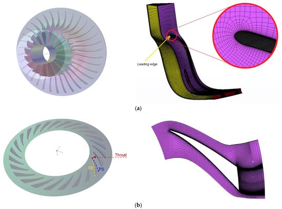
Figure 5.
Final geometry and mesh of the (a) blade and impeller passage, and (b) diffuser vane.
3.2. Mesh Independence Study
A mesh sensitivity study is necessary to ensure the independence of the results on the mesh size. The number of total nodes was investigated to examine the impact of the mesh refinement on the solution. To this end, the average values of flow temperature and density at the outlet were defined to be the indicative quantities. Table 6 presents these values as calculated by the various grids of different size. According to this table, both the outlet temperature and density exhibit relatively small deviations as the mesh gets thicker. The third mesh, with a total number of nodes equal to , is considered suitable as a compromise between the mesh size and solution accuracy, and this was finally adopted for the numerical simulation.

Table 6.
Properties variation at the outlet as the number of nodes increases.
3.3. Boundary Conditions
The commercial CFD solver CFX 18.1 [33], employing 3D Navier–Stokes equations, was adopted to perform all of the numerical simulations. For the computational method, based on a finite-volume approach, an implicit compressible formulation with second-order spatial discretization was used. The shear stress transport (SST) variant of the two-equation k-ω model was implemented to close the Reynolds-averaged Navier–Stokes equations. Steady-state CFD simulations were performed. For all calculations, the average y+ value was kept close to unity within the boundary layer. The reference pressure was set to zero and the rotational speed was equal to 7549 rpm. The heat transfer model for this study was selected as the total energy, including the option of viscous work. The total inlet temperature and pressure were selected as the inlet boundary conditions and are presented in Table 3. In particular, a stationary type of boundary condition was set at the inlet, where the initial turbulence intensity was chosen to be 5% and turbulence length scale 5% of the inlet mean diameter estimated from the 1D model.The mass flow was defined as a boundary condition for the outlet, also as stationary, while an active mass flow outlet constraint was set up. A smooth wall was assumed for the entire investigation. For the impeller, rotating boundary conditions were considered for its moving part, while the stationary parts of the compressor, namely the extended inlet, shroud and vaned diffuser, were specified as counter-rotating walls. Interfaces were set up within the tip clearance region. The modeling of a single passage was selected to save computational time; therefore, a component periodicity was selected, setting up periodic interfaces at the outer sides of the selected passage, which were modeled with the multiple reference frame (MRF) method between rotating and stationary domains. The convergence criteria of the calculation were based on the reduction in the RMS of momentum and energy residuals below 10−4, as well as the reduction in the RMS of the mass residual, stage polytropic efficiency and pressure coefficient below 10−6.
3.4. Real Gas Effect
The working fluid properties directly affect the solution of the Navier–Stokes equations. Thus, the consideration of real gas, employing the suitable equation of state for CO2 instead of that of perfect gas, is key to accurately solving the continuity, momentum and energy equations. However, the real gas properties of CO2 are not included in CFX libraries. These were included in an external look-up table, namely the real gas properties (RGPs) file, which was generated in-house on purpose and was coupled with the flow solver. The lookup tables include the metastable vapor region as defined by the thermodynamic model. Table 7 exhibits the deviation in the density between the model proposed by Span–Wagner (SW), which is considered as the most accurate for CO2 in the literature, and other models for carbon dioxide for conditions around the critical point. It is noticed that the model with the most significant deviation from the SW model is that of perfect gas, but none of the other EOSs deviate less than 13% with respect to the SW one.

Table 7.
Relative difference in CO2 density between Span–Wagner model and various EOS models for conditions of 7.69 MPa and 304.3 K.
Nine main properties were included in the real gas properties (RGPs) table: specific entropy, specific enthalpy, speed of sound, specific volume, specific heat at constant pressure and volume, dynamic viscosity, thermal conductivity and partial derivative of pressure with respect to specific volume at constant temperature. In order to produce the look-up table, a proprietary MATLAB code was developed that utilized fluid properties obtained from the NIST Refprop [34] database and applied the Span–Wagner model. The RGP table was generated within a temperature range of 290 to 400 K and a pressure range of 5 to 25 MPa, encompassing the entire operating range of the compressor and eliminating the need for extrapolations during the simulation. Additionally, in order to improve the accuracy of modeling CO2 behavior close to the critical point and address simulation instabilities arising from CO2’s significantly nonlinear behavior in the pseudo-critical region, an RGP table was designed with additional values in this region. This enables the solver to interpolate the properties between points of the table; thus, the solution accuracy could be affected by the number and distance of various states registered in the database, referring to the region in the vicinity of the critical point. In order to attain a suitably accurate solution, the RGP table with the required number of parameters was analyzed. Multiple ‘interpolating’ grids were selected and adopted in the examined region, augmenting the number of values in this area from 100 up to 600 points and evaluating variations in the specific heat capacity. Figure 6 illustrates the table’s precision at a constant pressure of 7.69 MPa, which corresponds to the compressor inlet pressure.
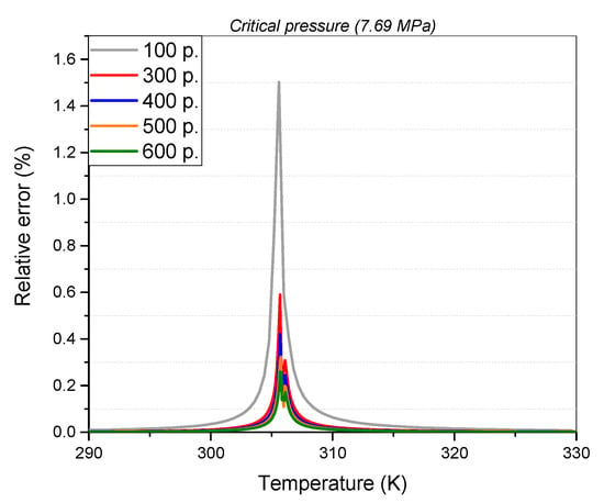
Figure 6.
Relative error of specific heat (cp) in the region around the critical point for pressure of 7.69 MPa as the points of the look-up table increase.
4. Results and Discussion
After carrying out the numerical simulations and performing the appropriate post-processing, the thermodynamic and aerodynamic characteristics of the flow for the design operating point of the compressor were examined. This section demonstrates the variation in the internal flow field of the supercritical CO2 along the impeller and diffuser paths. Moreover, the possibility of two-phase flow at the compressor inlet was investigated because of the vicinity of the inlet total temperature to the critical point.
Firstly, a comparison between the results of the mean-line analysis by the developed software tool and the CFD results is presented in Table 8 in terms of characteristic quantities that arise from the simulations. There is a very good agreement between the CFD analysis and the 1D model, exhibiting a maximum deviation of 2.5% found for the total pressure at the outlet.

Table 8.
Comparison between 1D mean-line and numerical results for validation.
Figure 7a illustrates a lateral view of the impeller showing the distribution of the total pressure at mid-span, while Figure 7b illustrates the total pressure at mid-span of the diffuser. The mean total pressure at the impeller outlet was calculated to be approximately 21 MPa, whereas its value at the diffuser outlet was 19.7 MPa.
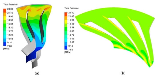
Figure 7.
Total pressure: (a) lateral view at impeller mid-span; (b) blade-to-blade view at diffuser mid-span.
Similarly, Figure 8a,b depict the field of the total temperature at mid-span along the impeller and the diffuser, respectively. The impeller outlet total temperature was estimated as 329.8 K and a similar value was predicted for the total temperature at the diffuser outlet.
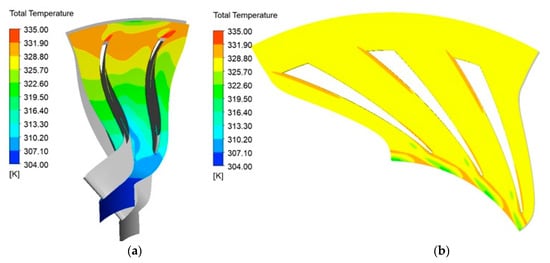
Figure 8.
Total temperature: (a) lateral view at impeller mid-span; (b) blade-to-blade view at diffuser mid-span.
As discussed above, the possibility of two-phase flow at the leading edge of the impeller was investigated due to the acceleration of CO2 being in supercritical state. Due to flow acceleration along the blade suction flow path, close to its leading edge, the sequence of working fluid states may cross the saturation curve, making it possible for condensation to exist. Figure 9 presents such a situation in a pressure–temperature diagram, showing how the flow from point A may cross the saturation curve passing to point C in the two-phase region, where liquid and vapor phases coexist. In the present study, an attempt was made to identify areas of potential condensation occurrence by examining the flow acceleration and pressure distribution at the blade.
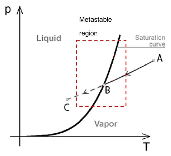
Figure 9.
Pressure–temperature diagram showing the process of condensation due to pressure drop.
Figure 10 illustrates the Mach number for the relative component of the velocity in a blade-to-blade view along the passages of the impeller and diffuser. It is observed that the flow accelerates along the blade’s pressure side at the leading-edge region as the relative Mach number increases. In order to examine the impact of this increase on the static pressure variation, Figure 11 presents the corresponding distribution of static pressure along the impeller and diffuser. As expected, in the region of flow acceleration, pressure locally decreases, and, due to the vicinity of inlet CO2 conditions to its critical state, the appearance of condensation at that region of the impeller is possible.
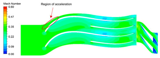
Figure 10.
Blade-to-blade view of Mach number distribution.
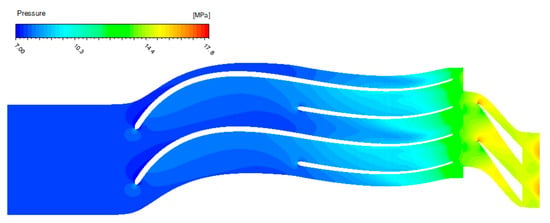
Figure 11.
Blade-to-blade view of static pressure field.
The Span–Wagner equation of state is accurate only in the stable region, whereas its extrapolation into the metastable region leads to unreliable results even from a qualitative point of view since the thermodynamic properties cannot be defined by this EOS. When the flow accelerates, a local expansion takes place. If the expansion process continues (condensation does not take place in an equilibrium state), the fluid is in a metastable region. Therefore, the fluid properties had to be calculated by CFX based on the values of the spinodal curves, showing local stability with respect to small fluctuations. In order to determine regions of possible condensation, the local value of the static pressure ratio was used as an indicator; ratio values lower than unity dictate regions of possible condensation. Figure 12 presents the contours of this ratio at the leading edge region of the blade suction side.
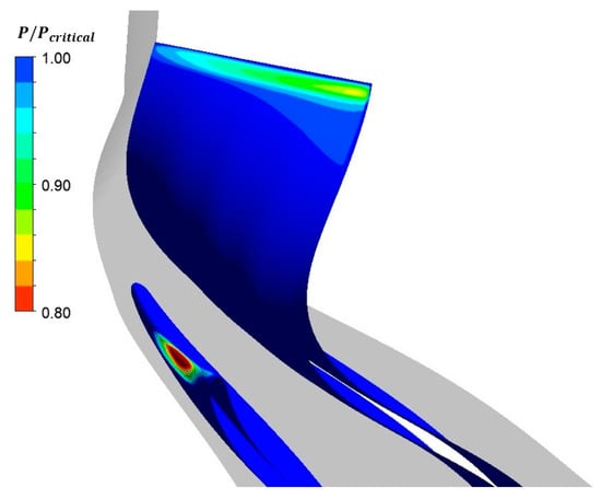
Figure 12.
Contours of the local flow ratio of pressure to saturation pressure at the leading edge of the suction side.
Furthermore, the creation of local super-volumes by means of stacking neighboring grid volumes that exhibit a ratio value lower than unity was implemented in order to visually locate the regions of potential supersaturation where condensation could start. These super-volumes are depicted in Figure 13, according to which, the extent of the possible two-phase flow region seems to be rather restricted and is considered to not be significant. However, a small change in the operating conditions, such as higher values of the compressor flow coefficient or higher rotational speeds, can increase the extent of this region and make it significant.
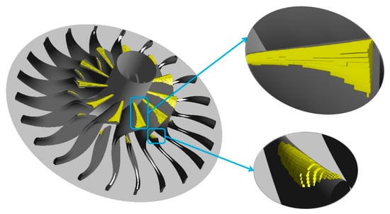
Figure 13.
Regions of possible condensation depicted as super-volumes at the leading edge of the main blade.
5. Conclusions
A preliminary design of the main centrifugal compressor of a recompression s-CO2 Brayton cycle was presented; this compressor is required to operate close to the critical point so as to minimize the compression work. A one-dimensional model was developed, utilizing pressure loss correlations available in the literature, concerning air as the working fluid. The model was validated against experimental results in predicting outlet conditions of a CO2 compressor with known geometry and inlet conditions (direct problem). The same model was then implemented to calculate the main geometric characteristics of a compressor with known inlet and outlet conditions (inverse problem). These conditions were dictated by a thermodynamic analysis of the aforementioned cycle. Subsequently, a fully three-dimensional numerical simulation of the designed centrifugal compressor was performed, considering a real gas behavior for CO2, instead of an ideal one.
The requirement of compressor operation in the vicinity of the critical point is crucial since small changes in flow properties there may result in significant changes in its performance. Thus, the accuracy of Span–Wagner EOS in evaluating real gas properties near the critical point was studied. In particular, the effect of the number of points used around the critical point in the look-up table was assessed. The use of 600 points was demonstrated to reduce the relative error to 0.3% compared to the use of 100 points. Minimizing the error in that region leads to smaller fluctuations in gas properties, which is expected to provide more credible CFD results.
Furthermore, the possibility of condensation at the leading edge of the impeller suction side was investigated, where local flow acceleration and a subsequent decrease in pressure and the speed of sound are expected. In order to identify regions of possible two-phase flow, the local ratio of flow pressure to saturation pressure was utilized. By demonstrating iso-surfaces of this ratio, possible two-phase regions were identified, confirming that the flow along the upper part of the impeller inlet may operate at risk of condensation.
The present work by the authors aimed to be a first step toward developing, in the long-term, numerical tools and knowledge for in-depth research on flow characteristics and the design optimization of compressors suitable for supercritical carbon dioxide cycles. A challenging objective for future research will be the redesign of the blade leading edge for avoiding the possibility of condensation, enhancing the margin of stable supercritical operation and improving the overall compressor efficiency.
Author Contributions
Conceptualization, A.A.G.; methodology, A.A.G. and D.G.K.; software, G.R.K.A.; validation, G.R.K.A. and A.A.G.; formal analysis, G.R.K.A. and A.A.G.; investigation, G.R.K.A., A.A.G. and D.G.K.; resources, I.E.S.; data curation, G.R.K.A.; writing—original draft preparation, A.A.G.; writing—review and editing, D.G.K. and I.E.S.; visualization, G.R.K.A. and A.A.G.; supervision, D.G.K. and I.E.S. All authors have read and agreed to the published version of the manuscript.
Funding
This research received no external funding.
Conflicts of Interest
The authors declare no conflict of interest.
Nomenclature
| A | Passage area (m2) | Δhs | Enthlapy difference (kJ/kg) |
| cp | Spec. heat capacity (J/kgK) | ρ | Density (kg/m3) |
| c | Absolute velocity (m/s) | σ | Slip factor |
| dt | Tip diameter (m) | Ω | Rotational speed (Hz) |
| Kdiff | Parameter of the diffuser’s curvature effect | ω | Pressure loss |
| lch | Channel width (m) | Subscripts | |
| L | Impeller length (m) | 1 | Inducer |
| Mass flow rate (kg/s) | 2 | Impeller inlet | |
| m | Meridional coordinate | 3 | Impeller outlet |
| Pr | Prandtl number | 4 | Diffuser inlet |
| ri | Radius (m) | 5 | Diffuser outlet |
| Re | Reynolds number | b | Impeller blade |
| t | Blade thickness (m) | ch | Channel |
| w | Relative velocity (m/s) | rad | Radial coordinate |
| Z | Number of vanes | d | Diffuser blade |
| Greek symbols | Abbreviations | ||
| α | Flow angle with tangential direction | s-CO2 | Supercritical carbon dioxide |
| β | Blade angle with tangential direction | LTR/HTR | Low/high-temperature recuperator |
References
- Feher, E.G. The Supercritical Thermodynamic Power Cycle. Energy Convers. 1968, 8, 85–90. [Google Scholar] [CrossRef]
- Angelino, G. Carbon Dioxide Condensation Cycles for Power Production. J. Eng. Power 1968, 90, 287–295. [Google Scholar] [CrossRef]
- Dostal, V.; Driscoll, M.J.; Hejzlar, P. High-Performance Supercritical Carbon Dioxide Cycle for Next-Generation Nuclear Reactors. Nucl. Technol. 2017, 154, 265–282. [Google Scholar] [CrossRef]
- Ehsan, M.M.; Awais, M.; Lee, S.; Salehin, S.; Guan, Z.; Gurgenci, H. Potential Prospects of Supercritical CO2 Power Cycles for Commercialisation: Applicability, Research Status, and Advancement. Renew. Sustain. Energy Rev. 2023, 172, 113044. [Google Scholar] [CrossRef]
- Bianchi, G.; Saravi, S.S.; Loeb, R.; Tsamos, K.M.; Marchionni, M.; Leroux, A.; Tassou, S.A. Design of a High-Temperature Heat to Power Conversion Facility for Testing Supercritical CO2 Equipment and Packaged Power Units. Energy Procedia 2019, 161, 421–428. [Google Scholar] [CrossRef]
- Ahn, Y.; Lee, J.; Kim, S.G.; Lee, J.I.; Cha, J.E.; Lee, S.-W. Design Consideration of Supercritical CO2 Power Cycle Integral Experiment Loop. Energy 2015, 86, 115–127. [Google Scholar] [CrossRef]
- Bae, S.J.; Ahn, Y.; Lee, J.; Kim, S.G.; Baik, S.; Lee, J.I. Experimental and Numerical Investigation of Supercritical CO2 Test Loop Transient Behavior near the Critical Point Operation. Appl. Therm. Eng. 2016, 99, 572–582. [Google Scholar] [CrossRef]
- Clementoni, E.M.; Cox, T.L.; King, M.A. Off-Nominal Component Performance in a Supercritical Carbon Dioxide Brayton Cycle. J. Eng. Gas Turbines Power 2016, 138, 11703. [Google Scholar] [CrossRef]
- Xu, P.; Zou, Z.; Fu, C. Aerodynamic Design Considerations for Supercritical CO2 Centrifugal Compressor with Real-Gas Effects. Energy Convers. Manag. 2022, 271, 116318. [Google Scholar] [CrossRef]
- Meshram, A.; Jaiswal, A.K.; Khivsara, S.D.; Ortega, J.D.; Ho, C.; Bapat, R.; Dutta, P. Modeling and Analysis of a Printed Circuit Heat Exchanger for Supercritical CO2 Power Cycle Applications. Appl. Therm. Eng. 2016, 109, 861–870. [Google Scholar] [CrossRef]
- Yao, L.; Zou, Z. A One-Dimensional Design Methodology for Supercritical Carbon Dioxide Brayton Cycles: Integration of Cycle Conceptual Design and Components Preliminary Design. Appl. Energy 2020, 276, 115354. [Google Scholar] [CrossRef]
- Liu, Z.; Luo, W.; Zhao, Q.; Zhao, W.; Xu, J. Preliminary Design and Model Assessment of a Supercritical CO2 Compressor. Appl. Sci. 2018, 8, 595. [Google Scholar] [CrossRef]
- Wright, S.A.; Radel, R.F.; Vernon, M.E.; Rochau, G.E.; Pickard, P.S. Operation and Analysis of a Supercritical CO2 Brayton Cycle; Sandia Report, No. SAND2010-0171; United States Department of Energy: Washington, DC, USA, 2010. [Google Scholar]
- Monge Brenes, B. Design of Supercritical Carbon Dioxide Centrifugal Compressors. Ph.D. Thesis, Universidad de Sevilla, Sevilla, Spain, 2014. [Google Scholar]
- Pecnik, R.; Rinaldi, E.; Colonna, P. Computational Fluid Dynamics of a Radial Compressor Operating with Supercritical CO2. J. Eng. Gas Turbines Power 2012, 134, 122301. [Google Scholar] [CrossRef]
- De Lorenzo, M.; Lafon, P.; Di Matteo, M.; Pelanti, M.; Seynhaeve, J.-M.; Bartosiewicz, Y. Homogeneous Two-Phase Flow Models and Accurate Steam-Water Table Look-up Method for Fast Transient Simulations. Int. J. Multiph. Flow 2017, 95, 199–219. [Google Scholar] [CrossRef]
- Baltadjiev, N.D.; Lettieri, C.; Spakovszky, Z.S. An Investigation of Real Gas Effects in Supercritical CO2 Centrifugal Compressors. J. Turbomach. 2015, 137, 91003. [Google Scholar] [CrossRef]
- Ameli, A.; Turunen-Saaresti, T.; Backman, J. Numerical Investigation of the Flow Behavior Inside a Supercritical CO2 Centrifugal Compressor. In Proceedings of the ASME Turbo Expo 2016: Turbomachinery Technical Conference and Exposition, Seoul, Republic of Korea, 13–17 June 2016. [Google Scholar] [CrossRef]
- Gou, J.L.; Zhang, K.L.; Ma, C.; Huang, C.H.; Chen, K.; Li, B.M. Numerical Investigation on Property Effects in a Low Speed Supercritical Carbon Dioxide Centrifugal Compressor. In Proceedings of the IOP Conference Series: Earth and Environmental Science; IOP Publishing: Bristol, UK, 2019; Volume 354, p. 12076. [Google Scholar]
- Saravi, S.S.; Tassou, S.A. Diffuser Performance of Centrifugal Compressor in Supercritical CO2 Power Systems. Energy Proc. 2019, 161, 438–445. [Google Scholar] [CrossRef]
- Lettieri, C.; Paxson, D.; Spakovszky, Z.; Bryanston-Cross, P. Characterization of Nonequilibrium Condensation of Supercritical Carbon Dioxide in a de Laval Nozzle. J. Eng. Gas Turbines Power 2018, 140, 41701. [Google Scholar] [CrossRef]
- Lüdtke, K.H. Process Centrifugal Compressors; Springer: Berlin/Heidelberg, Germany, 2003; Chapter 2. [Google Scholar]
- Span, R.; Wagner, W. A New Equation of State for Carbon Dioxide Covering the Fluid Region from the Triple-point Temperature to 1100 K at Pressures up to 800 MPa. J. Phys. Chem. Ref. Data 1996, 25, 1509–1596. [Google Scholar] [CrossRef]
- Zhao, Q.; Mecheri, M.; Neveux, T.; Privat, R.; Jaubert, J.-N. Selection of a Proper Equation of State for the Modeling of a Supercritical CO2 Brayton Cycle: Consequences on the Process Design. Ind. Eng. Chem. Res. 2017, 56, 6841–6853. [Google Scholar] [CrossRef]
- Correa, F.; Barraza, R.; Soo Too, Y.C.; Vasquez Padilla, R.; Cardemil, J.M. Optimized Operation of Recompression SCO2 Brayton Cycle Based on Adjustable Recompression Fraction under Variable Conditions. Energy 2021, 227, 120334. [Google Scholar] [CrossRef]
- Balje, O.E. Turbomachines—A Guide to Design, Selection, and Theory; John Wiley & Sons: Hoboken, NJ, USA, 1981; ISBN 0-471-06036-4. [Google Scholar]
- Wiesner, F.J. A Review of Slip Factors for Centrifugal Impellers. J. Eng. Power. 1967, 89, 558–566. [Google Scholar] [CrossRef]
- Oh, H.W.; Yoon, E.S.; Chung, M.K. An Optimum Set of Loss Models for Performance Prediction of Centrifugal Compressors. Proc. Inst. Mech. Eng. Part A J. Power Energy 1997, 211, 331–338. [Google Scholar] [CrossRef]
- Aungier, R.H. Centrifugal Compressors: A Strategy for Aerodynamic Design and Analysis; ASME Press: New York, NY, USA, 2019. [Google Scholar] [CrossRef]
- Monje, B.; Sánchez, D.; Savill, M.; Pilidis, P.; Sánchez, T. A Design Strategy for Supercritical CO2 Compressors. In Proceedings of the ASME Turbo Expo 2014: Turbine Technical Conference and Exposition; American Society of Mechanical Engineers, Düsseldorf, Germany, 16–20 June 2014; p. V03BT36A003. [Google Scholar]
- Schlichting, H.; Kestin, J. Boundary Layer Theory; Springer: Berlin/Heidelberg, Germany, 1961; Volume 121. [Google Scholar]
- Ansys Inc. ANSYS BladeGen, Release 18.2 Users Guide; Technical Report; Ansys: Canonsburg, PA, USA, 2017. [Google Scholar]
- Ansys Inc. Ansys Inc. Ansys Academic Research, Release 18.1. In Advanced Analysis Guide, Coupled Field Analysis Guide, Release 17.1 Doc; Ansys: Canonsburg, PA, USA, 2017. [Google Scholar]
- Lemmon, E.W.; Huber, M.L.; McLinden, M.O. NIST Reference Fluid Thermodynamic and Transport Properties—REFPROP; U.S. Department of Commerce: Gaithersburg, MD, USA, 2013. [Google Scholar]
Disclaimer/Publisher’s Note: The statements, opinions and data contained in all publications are solely those of the individual author(s) and contributor(s) and not of MDPI and/or the editor(s). MDPI and/or the editor(s) disclaim responsibility for any injury to people or property resulting from any ideas, methods, instructions or products referred to in the content. |
© 2023 by the authors. Licensee MDPI, Basel, Switzerland. This article is an open access article distributed under the terms and conditions of the Creative Commons Attribution (CC BY) license (https://creativecommons.org/licenses/by/4.0/).