1. Introduction
In recent decades, there has been a tendency not only to increase the efficiency of electric machines (EM), but also to decrease their mass-dimensional indices per unit of power. As a rule, this is carried out by the optimization of calculations and the use of three-dimensional modeling of physical processes (electromagnetic, mechanical, temperature, ventilation, etc.), as well as the emergence of new materials with improved parameters, which allows reduction of the weight of turbogenerator units.
Today, in Ukraine, almost 74% of electrical energy is produced at thermal and nuclear power plants, where turbogenerators are in operation. The service lives of most turbogenerators have already expired, and others are on the verge of expiration; this is due to long-term insufficient financing of the energy industry. At the same time, EM operating modes are complicated by uneven loads in the electrical network, which cause both generator overload (transition to emergency modes of operation, due to malfunction of generators at stations or an increase in the amount of consumed energy), and their shutdown (decrease in the amount of consumed energy). The solution to this problem is the partial modernization of already existing units with an increase in their capacity and the parallel, step-by-step replacement of the rest of the outdated machines with more powerful and lighter ones.
The development of a single methodology for calculating the stress–strain state (STS) for high-power turbogenerator units, based on a combination of analytical and three-dimensional calculations that allows increasing the accuracy of the calculation problem, is of great scientific and practical interest.
Let us consider the design of a two-pole turbogenerator manufactured by the EM WEG Group (USA) (see
Figure 1) [
1]. Application of the designs by putting into practice additional flexible elements, as a rule, is the most suitable method for turbogenerators rated over 100 MW.
The core fastening units include a system of prisms, which, with the help of pressing down flanges, keep the assembled core in a monolithic state. However, there are no springs in these suspensions that dampen the vibrational components of the harmonics of electric forces caused by gravity.
Classic designs of turbogenerators include two types of suspension, namely internal and external. One of the most striking and reliable representatives of turbogenerators with internal suspension are Turbogenerators rated 200 MW and 300 MW of the TGV series produced by the JSC “Ukrainian Energy Machines”. The design of the stator housing of an electric machine has been submitted in the scientific paper [
2]. In Refs. [
3,
4] the results of calculations of thermal fields in the end parts of the turbogenerator are presented. However, as operating experience shows, active cooling inside the rods and the high speed of the flowing refrigerant solve the problem of lowering temperatures in the end parts and their fastenings for the winding rods. Based on operating experience, the numerical solution for the frontal parts does not give an answer regarding the state of the grooves.
Figure 2 shows a serial sample and a longitudinal section.
Vibration is one of the important factors leading to the damage and destruction of turbogenerator housing parts. In Ref. [
5], the effect of vibration on turbogenerator assemblies is considered in detail. In turbogenerator design, the suspension (plate springs) takes the load caused by vibration forces and must ensure the safety of the structure when the unit enters the short-circuit mode. Other methods require optimization of the design to increase power while maintaining weight and dimensions [
1,
2,
6]. When solving these problems, it is necessary to pay attention to the level of vibration when carrying out tests [
7]. To ensure reliable operation, it is necessary to calculate the design of the suspension, which reduces vibration while maintaining the basic power.
2. Turbogenerator Suspension Design by JSC “Ukrainian Energy Machines”
In the given scientific paper, the strength of the structures of the internal suspensions of the stators of hydrogen-cooled turbogenerators rated 200 MW, 250 MW, 300 MW, and 325 MW, produced by JSC “Ukrainian Energy Machines” is studied. All the researched machines have a similar design of internal suspensions; the difference is in the number and geometric parameters of the suspension used.
In
Figure 3, the general view of the turbogenerator is submitted.
An analysis of the stress–strain state of the suspension unit, which includes a spring, a support plate, a strap, and a system of pins and bolted connections, was carried out (see
Figure 4).
The strength of the suspension unit was studied at the moment of a two-phase short- circuit, which corresponds to the maximum load on the suspension system. The occurrence of a short-circuit is characterized by the emergence of a moment of short-circuit of the MRC, which leads to compressive/stretching forces of the RKZ acting on the springs. The magnitude of these forces is determined for each machine by classical analytical methods of calculating the suspension of the stator core during a two-phase short-circuit, in accordance with the technical conditions for Turbogenerators TGV-200, TGV-300 series, manufactured by JSC “Ukrainian Energy Machines”. The calculation is carried out for the case of static loading of the suspension system by the compression/tension force of the RKZ, while a dynamic factor is chosen equal to 2.
The rated torque acting on the stator of the generator is determined by the following formula:
where
N is the power of the generator and
n is the rotational speed of the generator per minute (rpm).
Forces on the vertical spring at rated mode are calculated as per the following formula:
where
G is the stator mass,
zB is quantity of vertical springs,
is the power factor,
z is the general quantity of the springs, and
R is the radius of the spring arrangement.
At short-circuit mode, this force is determined as:
where
is force, which acts on the spring at a sudden two-phase short-circuit on the terminals.
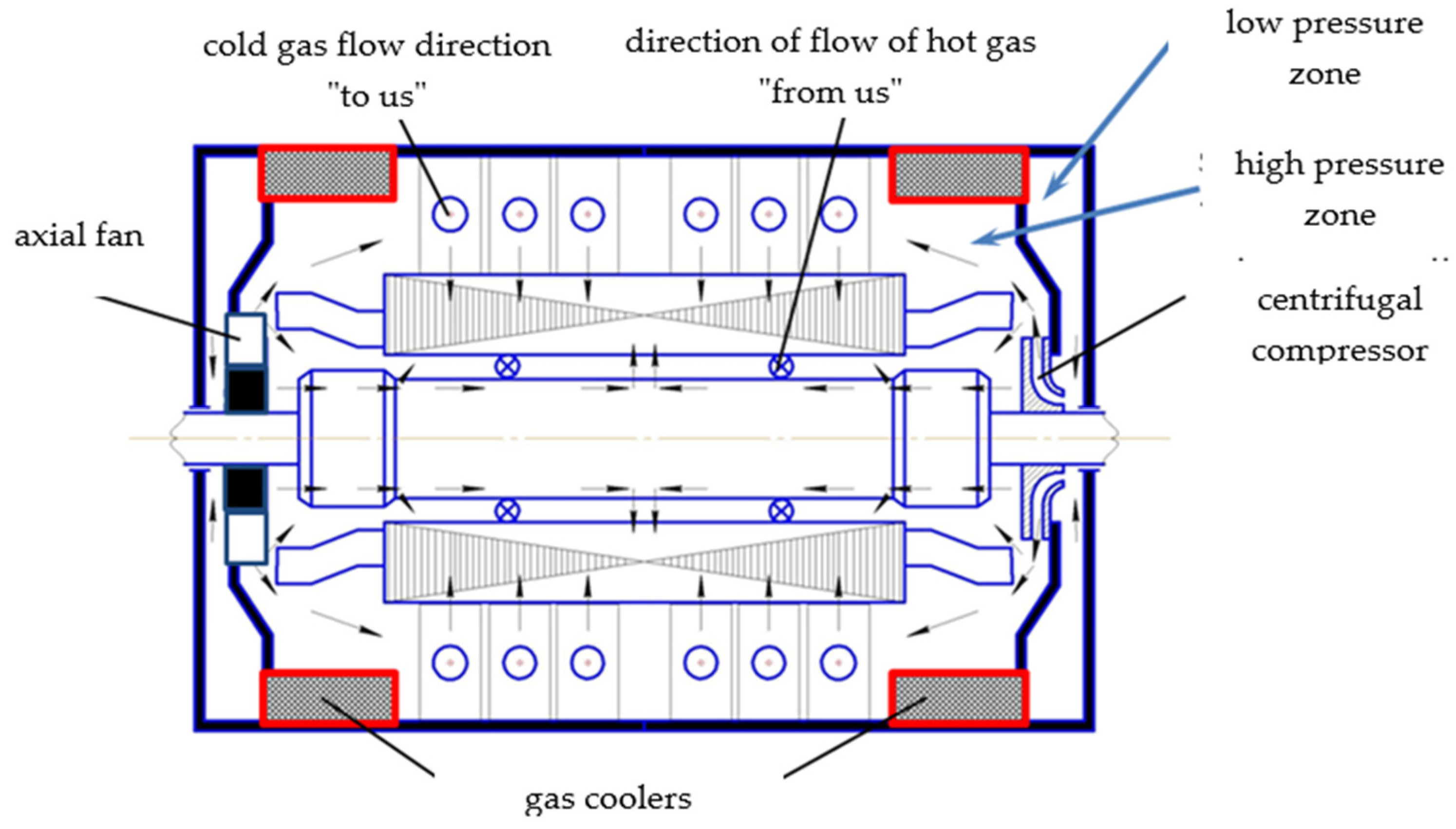
In addition, the influence of temperature loads on the suspension is taken into account, which vary along the length of the stator core and are determined to take into consideration the internal heating of the stator with the solution of the gas-dynamic problem. According to the experience of operating turbogenerators rated 325 MW with hydrogen cooling, the temperature difference between the core and the stator casing can be 60 °C which is confirmed by calculation data. According to the calculation data for a turbogenerator rated 250 MW with hydrogen–water cooling, the temperature of the “active steel” of the stator on the side of the slip rings is 36 °C, in the middle of the machine is 39 °C, and on the side of the turbine is 41 °C. The gas temperature in the radial channel is in the range of 25 °C to 47 °C. The hottest point of the gas on the stator is 47 °C and is located in the second compartment in the area of the backrest. The gas temperature increases from the tooth to the back by ~10 °C. The turbogenerator cooling system is shown in
Figure 5.
The longitudinal ventilation channels are shown in
Figure 6. The springs are inside the stator.
Therefore, for each row of springs, it is necessary to determine the mechanical stresses, taking into account the change in their thermal state. Determination of the temperature field in parts of the suspension unit is performed by solving the unsolved thermal problem, applying boundary conditions of the first kind.
Thus, the calculation of the suspension is carried out for the axial tension/compression forces acting on the spring at short-circuit and are determined according to the classical engineering methods used for the calculation of the suspension of turbogenerators. With that, the temperature loads on the suspension assembly unit mentioned above are taken into account. This allows for a more accurate description of the real stress–strain state (STS) in the suspension assembly unit.
The general view of the suspension of the considered turbogenerators is shown above in
Figure 4. The suspension consists of vertical and horizontal flat springs, one end of which is fixed to the stator casing, and the other is fastened to the frame. The number of stator spring suspensions for generators, even those of the same power, may vary. At the same time, depending on the power of the generator, the geometric parameters of the suspensions and the load acting on them change. Further, a study of the strength of the suspension unit for generators rated 200 MW, 250 MW, and 325 MW is performed.
The purpose of the calculation is to define the stresses in the suspension spring and the details of its fastening to the stator casing and to the frame in case of a short-circuit in the stator winding, taking into account the unevenness of temperature loads and possible assembly inaccuracies.
3. Study of the Strength of the Stator Suspension of Generators Rated 325 MW and 250 MW
The main geometric and physical characteristics of the suspension of the turbogenerator rated 325 MW, 3000 rpm are as follows:
| G = 185,000 kg; |
| Z = 20 pcs.; |
| h = 1.8 cm; |
| b = 20 cm; |
| l = 65 cm; |
| F = b × h = 20 × 1.8 = 36 cm2; |
| L = 85 cm; |
| R = 147.4 cm. |
The amplitude value of the moment during a short-circuit is equal to Msh.c. (MKZ) = 2.62 × 10⁸ kg cm, and the maximum force on one spring from the torque during a short-circuit is P2 = 89,000 kg.
The stator core of the generator rated 325 MW is attached to the housing with 10 horizontal and 10 vertical springs. Fastening with the help of 16 springs is also used.
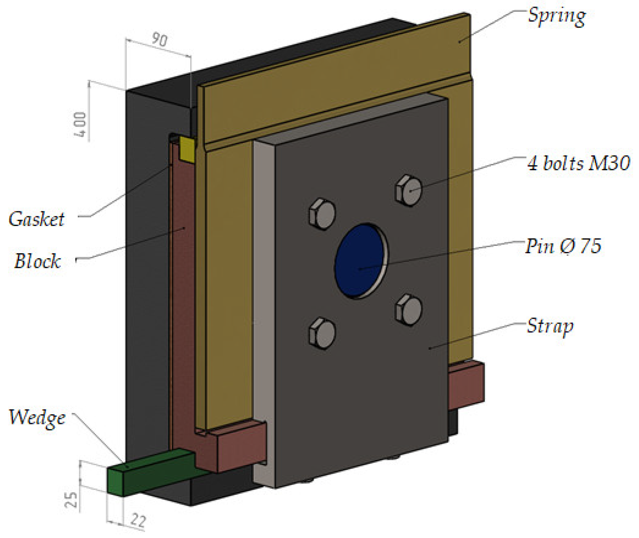
Figure 7 shows the fastening unit for attaching the spring to the frame.
Similar images of the method of the fastening of the spring to the stator casing are shown in
Figure 8 and
Figure 9.
A plate with mounting holes is welded to the frame, to which a spring is attached and fixed with a strap. In the generator rated 250 MW and 320 MW, the spring is attached to the frame with a conical pin with a diameter of 60 mm, 5 conical pins of 30 mm, and 4 bolts, M30.
The spring is attached to the stator casing with a pin and a strap. In the generator rated 250 MW, the spring is attached for support with a conical pin with a diameter of 60 mm and three bolts, M30. A sleeve welded to the rings of the stator casing is installed on the cylindrical ends of the supports with tension. The conical pin is held on one end by a support, and on the other by a cheek, which is attached to the support with two bolts, M36, working in tension. Thus, the pin has two planes of cutting. On a generator rated 320 MW, fastening is carried out with one pin with a diameter of 60 mm and 4 bolts, M36.
The material of the suspension and pins is alloyed steel.
In
Figure 10, a calculation diagram with the main loads acting on the support elements of the suspension and the temperature of its elements is shown, where the numbers 1, 2, and 3 indicate the support pins, and 4 indicates the main body of the spring, the directions of forces are indicated by arrows. T1, T2, T3, and T4 are the calculated temperatures of the suspension elements.
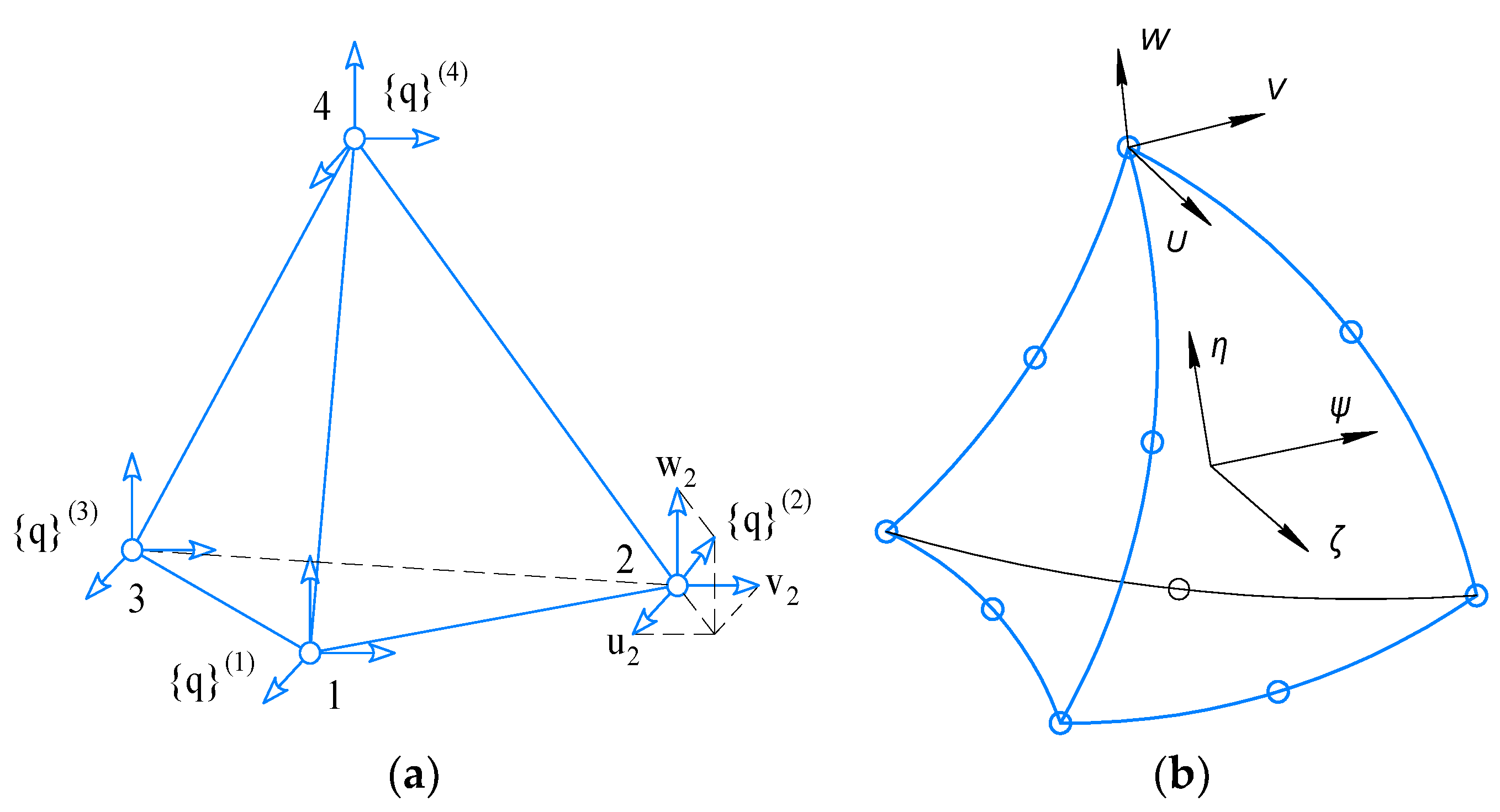
One of the defining moments in solving MSE problems is the choice of a finite element. Two types of tetrahedrons (
Figure 11) are used as basic finite elements with different approximations of movements inside the element. The first tetrahedron has units at the tops (
Figure 11a) and is based on a linear approximation of movements inside the element, and the second is an oblique tetrahedron that has units at the tops of the element and in the middle of its edges; it is based on a quadratic approximation of movements inside the element (
Figure 11b).
An oblique tetrahedron allows more accurate description of the geometry and deformation process of the research object; however, it has 10 internal units and contains 30 unknown values, which is almost three times the number of unknowns for an ordinary tetrahedron with four units and, accordingly, with 12 unknowns values sought for.
Therefore, a classical tetrahedron will be used for a qualitative study of VAT parameters, and an oblique one will be used for more accurate, final calculations. In SolidsWork, which is used to solve these problems, these are TETRA4 and TETRA10 finite elements, respectively [
8].
The influence of temperature fields leads to the emergence of additional temperature deformations [
9,
10,
11]
where α is the coefficient of linear temperature expansion of the material,
T =
T(
x,
y,
z)—is the temperature distribution obtained from solving the thermal conductivity problem, and
T0 is the temperature at which there are no thermal stresses in the material.
The general deformation of the body consists of elastic deformations and temperature deformations [
10]:
where
elastic deformations.
Taking into account temperature deformations, the relationship between stresses and deformations takes on the form:
Let us imagine (6) in matrix form:
where
.
In Ref. [
12] the methods for mesh decomposition have been submitted; however, this method cannot be fully applied due to the significant difference between fasteners and main structural elements. A significant contribution to mesh adaptation can be made by improved shape optimization based on mesh [
13]. When constructing the mesh, we relied on the results given in Ref. [
14]. It should be noted that, when using second order equations in numerical methods, the mesh was smoothed at the contact points of the elements. Taking into account the results of [
14,
15,
16,
17,
18], the mesh was adapted, while at the attachment points and small elements, the mesh was thickened from the condition that, for conical surfaces, the stress during mesh discrediting should not differ by more than 0.1%.
In
Figure 12 show basic grid for calculation.
The stress–strain state of the assembled unit at compression is shown in
Figure 13a, and when stretched is shown in
Figure 13b.
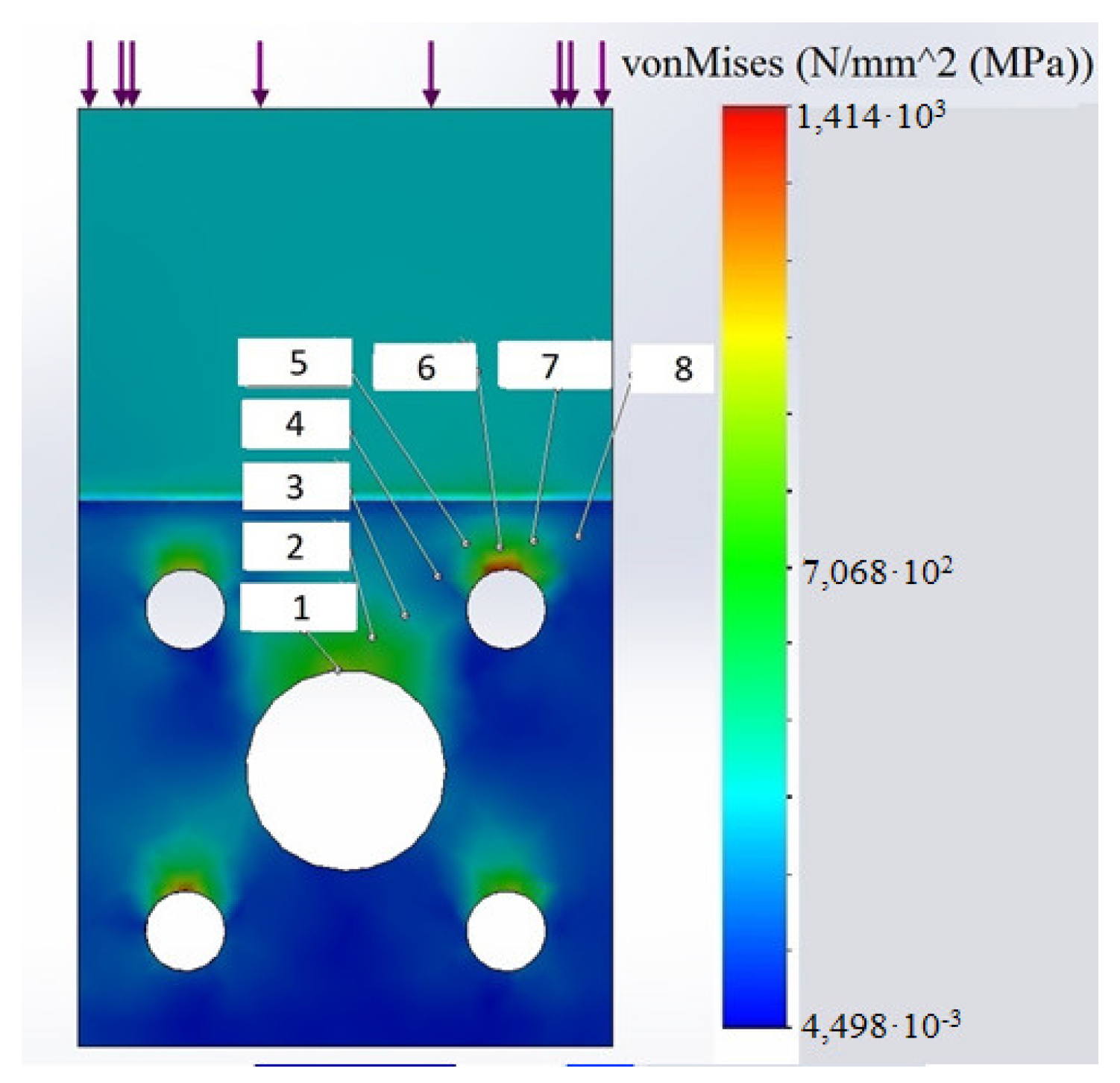
In
Figure 14 and
Figure 15, the stress field on the spring surface and the diagram of stress changes along the curve, which is marked with numbers from 1 to 8 in the Figure, during compression is shown. As expected, there is a significant stress concentration near the holes.
The total stress values were analyzed for von Mises stresses. With that, the experience presented in Refs. [
19,
20,
21,
22] was taken into account.
In the process of correlation of the calculations obtained by the FEM, the values calculated using engineering methods were compared, as well as the actual stresses obtained by measuring with strain gauges.


 ,
, 


