Article

Hardware Validation for Semi-Coherent Transmission Security †

by
Michael Fletcher
1,2,
Jason McGinthy
3 and
Alan J. Michaels
1,2,*
1
Virginia Tech National Security Institute, Blacksburg, VA 24060, USA
2
Bradley Department of Electrical & Computer Engineering, Virginia Polytechnic Institute and State University, Blacksburg, VA 24060, USA
3
United States Air Force Academy, Colorado Springs, CO 80840, USA
*
Author to whom correspondence should be addressed.
This article is a revised and expanded version of a paper entitled Semi-Coherent Transmission Security for Low Power IoT Devices, which was presented at the July 2018 IEEE International Conference on Internet of Things (iThings-2018) in Halifax, NS, Canada, 30 July–3 August 2018.
Information 2025, 16(9), 773; https://doi.org/10.3390/info16090773
Submission received: 20 March 2025 / Revised: 26 August 2025 / Accepted: 2 September 2025 / Published: 5 September 2025
(This article belongs to the Special Issue Hardware Security and Trust, 2nd Edition)

Abstract

The rapid growth of Internet-connected devices integrating into our everyday lives has no end in sight. As more devices and sensor networks are manufactured, security tends to be a low priority. However, the security of these devices is critical, and many current research topics are looking at the composition of simpler techniques to increase overall security in these low-power commercial devices. Transmission security (TRANSEC) methods are one option for physical-layer security and are a critical area of research with the increasing reliance on the Internet of Things (IoT); most such devices use standard low-power Time-division multiple access (TDMA) or frequency-division multiple access (FDMA) protocols susceptible to reverse engineering. This paper provides a hardware validation of previously proposed techniques for the intentional injection of noise into the phase mapping process of a spread spectrum signal used within a receiver-assigned code division multiple access (RA-CDMA) framework, which decreases an eavesdropper’s ability to directly observe the true phase and reverse engineer the associated PRNG output or key and thus the spreading sequence, even at high SNRs. This technique trades a conscious reduction in signal correlation processing for enhanced obfuscation, with a slight hardware resource utilization increase of less than 2% of Adaptive Logic Modules (ALMs), solidifying this work as a low-power technique. This paper presents the candidate method, quantifies the expected performance impact, and incorporates a hardware-based validation on field-programmable gate array (FPGA) platforms using arbitrary-phase phase-shift keying (PSK)-based spread spectrum signals.

1. Introduction

As the Internet of Things (IoT) continues its rapid growth [1], information security strives to meet the goal of Shannon’s perfect secrecy [2]. More private information will intentionally or unintentionally be transmitted from everyday devices throughout our homes, workplaces, or our random daily interactions and must be protected. Many of the devices that will be connected through the IoT have limited capabilities due to low power, memory, and computational ability. Due to these drawbacks and others, such as narrow bandwidths, signal interference from many networked devices, and constrained transmission ranges, IoT device networks are highly susceptible to environmental factors as well as cybercriminals [3,4]. Therefore, practically implementable low-power solutions are desired to ensure that critical information is protected [5,6,7]. In the context of IoT networks, critical information may refer to cryptographic keys, patient biometric health data, and real-time control parameters in industrial processes, among many other types of privileged data. Oftentimes, this protection is multi-layered and can be achieved through secure waveform design [8,9,10], operating at or below the noise floor [11,12], employing difficult-to-measure channels or geometries [13,14], or the use of cryptographic processes. It is worthwhile to note that the real-time subset of cryptographic protocols called transmission security (TRANSEC) [15,16] has specific benefits for latency. This paper focuses on a low-power, physical-layer TRANSEC method for IoT-constrained devices that is built on top of arbitrary-phase spread spectrum communication signals.
Historically, physical (PHY)-layer security and TRANSEC have been shown through theoretical means [17,18,19,20,21]. A large body of work focuses on physically uncloneable functions (PUFs) [22,23], many of which require direct physical access to the device. A variety of different wireless methods have been employed to achieve this security. Such work, as presented in [24], relies on time-division multiple access (TDMA) multi-user diversity based on channel state information (CSI). Another method described in [25] uses the random positions of sub-carriers in orthogonal frequency division multiplexing. A final method for 5G cellular communications attempts to exploit multiple-input multiple-output (MIMO) propagation paths to isolate energy received by a potential attacker [26]. Other approaches rely on RF channel characteristics such as multipath or complete RF fingerprinting [27].
These methods mainly focus on using known channel characteristics to change the timing of transmissions. However, it may not be feasible to know the current CSI for low-power devices, and the extra computation to continually monitor and adjust them adds battery drain. In other cases, security methods like RF fingerprints may be susceptible to small shifts in environmental temperature or other signal variations [28]. Therefore, a pseudorandom process is desired to change the physical characteristics of the signal components, reducing the probability of reverse engineering by an attacker [29].
By changing the physical transmission modulation properties of the signal in a pseudorandom yet constrained manner, the PHY-layer security allows the transmitter and receiver to remain synchronized, but it should not allow an eavesdropper to easily track the signal phase and subsequently use that phase to cryptanalyze the underlying pseudorandom number generator (PRNG) used to map the signal phase. By retaining the bulk phase of a spreading chip and only dithering over a small region, with that phase dither term optionally being uncorrectable, the intended receiver may still receive and demodulate the signal with only a small loss [30]. This paper expands upon the prior work of [30] with hardware validation on live FPGAs. As such, the inherent security benefit of a time-evolving spreading code can be ensured [31,32].
While the original conference paper focused on the theoretical feasibility and simulation-based analysis of the proposed approach, the current work delivers a full hardware implementation on an Intel Arria 10 system-on-chip (SoC) field-programmable gate array (FPGA) platform, complete with empirical validation using point-to-point transmissions. Key contributions include detailed measurements of block error rate (BLER) performance under varying phase distortion levels, hardware resource utilization breakdowns, and the practical impact of the method on real-world packet detection and decoding. These results confirm that the security-performance trade-off is viable in practice, with a less than 2% increase in hardware resources and minimal degradation in performance at moderate levels of induced phase noise (e.g., ψ = π / 8 ). This paper also compares the proposed method against other TRANSEC techniques and positions it as a compelling solution for low-power IoT communications.
However, if an eavesdropper is able to gather enough of the transmitted signal, a layer of data encryption will still be in place to keep the data secret. Compared with symmetric encryption schemes, current asymmetric encryption techniques such as RSA and elliptic curve cryptography (ECC) [7,33] require more memory and power [34] and are generally more difficult to implement in resource-constrained IoT devices [35]. Thus, lightweight, symmetric approaches are currently being considered, such as the Advanced Encryption Standard (AES) [36] and Galois Extension Field (GEF) techniques.
Given the proposed approach being a semi-coherent adaptation of the spreading code, this simpler, lower-power technique is expected to slightly degrade the communications system performance. Despread symbol energies will be lower than in the ideal coherent case, yet they are not expected to significantly impact the system throughput or reliability. Hardware validation is particularly important, since the aggregation of symbols as packets or data frames also aggregates the despread symbol energies as soft symbols for forward error correction (FEC) decoding. Phase and frequency tracking loops also rely on these symbol energies over the duration of the packet and should be considered. The packet error rates are thus expected to be lower overall than the symbol energy degradations; this performance metric is highly dependent on specific implementation details and is most suitable for real-world hardware measurements.
The overall contribution of this paper is the obfuscation of a spread spectrum signal by intentionally injecting noise into the phase mapping process of a spreading chip selection to decrease an eavesdropper’s ability to directly observe the true phase and reverse engineer the associated PRNG output or key, even at high SNRs. The rest of this paper is organized as follows. Section 2 provides an overview of a code division multiple access (CDMA) PHY-layer communication system for this semi-coherent approach. Section 3 describes the integration of the injected semi-coherent signal phases in detail, and Section 4 presents an exemplary design implementation along with results based on simulations of the design. Next, Section 5 describes the hardware validation results on an FPGA-based platform. Finally, Section 6 offers the conclusions and associated applicability to low-power IoT devices.

2. System Overview

2.1. Spread Spectrum Modulation

In spread spectrum baseband modulations, each data symbol is spread over a larger bandwidth using a spreading sequence of N chips. For the purpose of this paper, we assume, without loss of generality, that N is chosen as a fixed integer, eliminating the need for resampling filters at the symbol boundaries. In some applications, this process allows the signal to be hidden below the noise floor [37], while in commercial IoT applications, this spreading and despreading process offers a viable simplification of co-channel contention processes and built in resilience [38] against natural and man-made interference. Similar sequence-based spread spectrum methods are used in the GPS [39], secure digital chaotic sequence spread spectrum (CSSS) systems [40], and commercial datalinks like IEEE 802.11b [41] and CDMA2000 [42]. Waveforms designed specifically for security tend to use complex-valued or arbitrary-phase spreading chips, which may be thought of as being drawn pseudorandomly around the unit circle as opposed to from a small number of discrete constellation points. Since each data symbol is mixed with N chips, the chipping rate is much faster than the data rate, typically by a factor of 100–1000. Therefore, a fast chipping rate, which ultimately defines the spread bandwidth, is ideal to allow a larger value of N chips per symbol.
On the receiving end, the signal is despread using the time-synchronized complex conjugate of the spreading sequence to reconstruct the original data symbol. For real-valued spreading sequences, the conjugate is in fact the same as the spreading sequences, making the conjugation critical for arbitrary-phase sequences. The more chips used in the spreading sequence (typically increasing the chip rate), the higher the processing gain [37]; however, in real-world envrionments, longer spreading codes make the signal more susceptible to frequency offsets (static offset, doppler effects, fading channels, etc.), which may make the signal harder to recover in certain situations. The resulting expected energy per symbol ε s is based on the number of chips used in the spreading sequence N and the energy per chip ε c , as captured in Equation (1):
E [ ε s ] = N ε c .
A conceptual view of the proposed spreading and despreading process is illustrated in Figure 1. The PRNGs of both the transmitter and receiver are time synchronized with the same session key, producing a coherent phase θ . Each data symbol is mixed with a spreading code of N chips, each with a coherent phase θ and an induced phase error ψ , and then transmitted to the receiver. This additive phase error is assumed to be applied at the same chip rate as the primary spreading operation, yet this can be performed at any subdivider of the rate without impact.
The receiver then attempts to derotate the spreading chips’ phases with the complex conjugate of θ . An optional phase derotation may occur if synchronization of the induced error is achievable. Finally, the signal is mapped and passed through an accumulator to produce the data symbol. Note that α may be a function of time ( α ( t ) ) or any other desired parameter, including the SNR or other observables at the intended receiver.
One advantage of using spread spectrum modulation with TRANSEC is the added parameters for the chips and spreading sequence. This paper generally assumes the use of high-order PSK signaling (HOPS) [43] or digital chaotic sequence spread spectrum signaling techniques, where chip phases are drawn from relatively large M-ary PSK constellations on the unit circle. Any other arbitrary-phase spread spectrum signal, including chaotic signals [44], may be used without changing the fundamental approach. As long as the transmitter and receiver employ a time-synchronized spreading code, the individual phase of each chip can be altered to reduce the likelihood of an attacker reverse engineering the modulation scheme [45]. The phase of each chip does not have to be the same and can be synchronized by the receiver. Therefore, adding a small error to each chip’s phase will add an additional layer of obfuscation for the PRNG output and its associated key, which is producing the true phase of each chip.
One of the key origins of the desire for this small phase perturbation is that the phase of most chaotic-based spread communication systems can be translated back to the current state of the underlying chaotic sequence-generating circuit [46]. In the process, it is relatively easy to quickly identify the full system state and trajectory, synchronizing a replica of the chaos-based PRNG for further attacks. Incorporating non-recoverable phase errors into this output state enhances the difficulty of reverse engineering the underlying system state, which in turn improves security. Most cryptographic processes in general are not robust in the presence of state errors, and thus it is this inferred relationship between the signal phase and system state that we seek to obfuscate.
The primary focus for this paper is hardware validation of this intentional dithering of the instantaneous phase of each chip, which was previously demonstrated to be successful in simulations [30]. Since the transmitter and receiver will have a synchronized true phase and only a small error added on the transmitter side, the resultant phase error produces a semi-coherent signal for the receiver. Our hardware validation demonstrates that while the necessary phase error needed to eliminate the linkage to the system state is rather small, the resilience of a spread spectrum system to relatively large per-chip phase variations is extraordinarily high. Figure 1 highlights the addition of this phase error as well as the synchronization between a transmitter and receiver, yet the relative magnitudes of the phase variations are of particular interest.

2.2. Semi-Coherent TRANSEC

Many TRANSEC approaches rely on the low probability of an attacker synchronizing with a transmitting device, but a 0% probability is never a guarantee. Whether the result of a faulty implementation [47] or the development of improved methods for reverse engineering [48], it is possible that any chosen sequence generation method in use today may present a vulnerability tomorrow. Therefore, adding a second layer of phase perturbation, even if it has a non-repeatable PRNG or a true RNG, results in a noisy signal from the perspective of the intended (now semi-coherent) receiver yet also a substantially more secure signal from the perspective of an attacker.
A system needs sufficient security in the underlying TRANSEC architecture to reduce an attacker’s ability to reverse engineer the process, yet in the IoT, the computational burden borne by this processing must remain extremely low to be practically implementable. Many times, a protected session key is used to derive the physical characteristics of the transmitted signal. One approach to reducing the likelihood of an attacker compromising the entire system, as presented in this paper, is to add an induced error to the phase mapping that obfuscates the actual derived phase, thereby making it more difficult for the PRNG output and therefore the session key to be determined. Moreover, this error should not unduly degrade the receiver’s ability to receive the signal correctly, but the minor perturbation should make it increasingly difficult for an attacker to know the original value used in the parameter selection. Without this mapping value, cryptanalysis attempts explode into a stochastic search over a much larger search space.

2.3. Session Key Protection

Session keys and their synchronization amongst devices provide an authentication mechanism, as only authenticated users should have access to the session keys. A variety of session key derivation and distribution methods have been developed for the IoT [49,50], with the greatest emphases being on computational complexity and latency. Therefore, any ability of an outside observer to reverse engineer any portion of this security scheme should be reduced. The main area of focus for this paper is the phase of a transmitted sequence-based spread spectrum signal. An attacker must not be able to observe a stream of transmitted signal phases and determine any information that may be used to decipher a session key from those signals. Therefore, our proposed method for reducing the likelihood of this attack is introducing a semi-coherent (By choosing a constrained non-coherent phase value to be added to the coherent chip phase, the actual PRNG-driven signal is obfuscated, and yet the resulting semi-coherent aggregate signal still contributes to lossy coherent gain in recovering the spread data symbol.) phase offset error to the actual phase, which should make it infeasible for an attacker to know what the original phase is, effectively obfuscating the associated session key. The chosen shaping of the PRNGs discussed can take any form desired, through our general assumption for optimizing spread spectrum communication performance is a symmetric zero-mean distribution. Note that the session key distribution and synchronization methods would run at the user data layer and thus are not directly affected by the chosen reductions in signal coherence beyond the resulting self interference.

3. System Design

This overall concept of semi-coherent TRANSEC is focused on an induced error, the instantaneous phase error produced, and the impacts this error has on both the chip and symbol energies when received. This section details the different sources of error as well as the construction of symbol energy calculations based on different distributions of the error. As will be seen in these calculations, the spread spectrum aggregation of symbol energies from a large collection of chip energies enables robust approximation of the anticipated error(s) given knowledge of the chip-level error distributions.

3.1. Perturbation Types

Many different approaches exist for the generation of the induced error. Both non-determinsitic and deterministic methods may be considered. Non-deterministic use cases include the adaptation of non-repeatable physical processes (TRNGs deriving their values from ambient temperature or voltage changes) or intermediate calculations of incoming RF noise sources that may or may not have been shaped to easily estimable or time-invariant distributions. On the other hand, deterministic models can employ an independent PRNG or any other shared computational process that is not easily evident in signal outputs (e.g., the number of rollover events in a modular reduction). The following examples highlight the advantages and disadvantages of certain types of error injection.

3.1.1. Truly Random Number

A true random number generator (TRNG) may be implemented into the system to make it exceedingly difficult for an attacker to guess the non-deterministic outputs of the RNG. TRNGs should produce a stream of values with no pattern or periodicity, confounding an attacker’s ability to remove the error. Generally, TRNGs are unable to generate random numbers as quickly as other pseudorandom processes [33,51]. Therefore, a TRNG may not be appropriate in contexts where random numbers are needed at a fast rate, since it binds the masking non-coherent phase rotations to a potentially low-entropy process when taken at the rate of a spread spectrum communication system. Moreover, by design, a TRNG cannot be synchronized at the intended receiver, eliminating any potential for reducing the effective SNR loss if desired or required. Given the incompatibility in the generation rates of good TRNGs and the rates needed for real-time signal spreading, the option exists to either use a lower-entropy approach that can suport the full rate [52,53] or recycle results in a way to allows for higher usage rates, even if patterns exist.
This paper focuses on the unsynchronized PRNG, yet the design of this architecture should be independent of the chosen random number generation technique. All that may be known about this value is its distribution (i.e., uniform, normal, etc.). It shall have a mean μ and variance σ 2 . An observer may be able to know the range of the random number and calculate the mean, but the range should be large enough that it is infeasible to easily guess the number. Therefore, an attacker may only be able to use the mean and variance to try to deduce the value of the random number. Further, by choosing the unsynchronized PRNG over the other options, we ensure the use of currently available RNG capabilities yet without any added TRANSEC synchronization requirements.

3.1.2. Unsynchronized Psuedorandom Number

A completely unsynchronized psuedorandom number generator (PRNG) may be used to generate minor perturbations while making it extremely difficult for an attacker to guess the output. Although not truly random, a residue number system (RNS)-based PRNG [54] has a rather high throughput, allowing faster generation of numbers compared with many TRNGs. Independence of two RNS-based PRNGs, which may also be viewed as the elimination of code synchronization (not time synchronization), is easily achievable by choosing co-prime residue sets. Numerous other high-rate PRNG processes may be used without loss of generality [55,56,57], recognizing that absolutely no effort is invested in synchronizing or making the PRNG repeatable. However, one must be mindful when choosing a PRNG as they are deterministic and periodic. Moreover, there is strong interest in having the option to synchronize PRNG outputs, which requires moving forward or backward in code space without calculating all intermediate states.

3.1.3. Synchronized Psuedorandom Number

A third option for generating the non-coherent phase addition to the signal chip phase is to use a synchronizable PRNG. This allows for selective dissemination of the additional PRNG parameters to trusted partners within the communication network so that they can achieve fully coherent processing of the incoming signal (no loss) while semi-trusted nodes within the network proceed with a parametrically controlled amount of self interference within the signal. Such layered security techniques combine traditional TRANSEC protection with PHY-layer processing constraints and may be useful for key transfer, network formation, key revocation, and adaptively controlled transmission of data in a unicast or sub-net specific fashion over a public channel. The use of the previously mentioned RNS-based PRNG meets this objective easily, as does using the non-final outputs (with finite memory) of any chosen PRNG. Similar self-interference techniques have been proven for PHY-layer-only physical processing.

3.1.4. Markovian Process

The final option identified is a Markovian process that would be stochastically state-driven and configured based on given probabilities while still having some uncertainty of the next value. One prime example of this process is a random walk. Given the memoryless property of Markov chains, the past trajectory is irrelevant, and the future is still uncertain, yet the long-term stochastic averages may be predicted with prior knowledge of the transition matrix. Such methods may be used by an intended receiver to coarsely synchronize to the injected phase errors, even without knowledge of the actual perturbation signal source.

3.2. Phase Modulation

An individual baseband spreading chip may be represented by
c [ n ] = e j ϕ
where ϕ is the phase for each chip. It is assumed that the center frequency and timing of the spread spectrum signal are synchronized, leaving only the signal phase to be considered for individual data symbols. Optionally, the added phase perturbations can be eliminated during preamble transmission to eliminate interactions with tracking loops. The selection of changing the phase of a signal has many benefits. A phase change can be instantaneous per chip and is incredibly easy to control, since the phase will be added to the already randomly chosen chip phase. The addition of a phase offset leads to added security with the trade-off of a reduction in received signal quality. We will consider both cases of near-continuous phase perturbations in Section 3.2.1 and truly discrete phase perturbations in Section 3.2.2.
The chip’s phase, ϕ , can be expanded as follows:
ϕ = θ + ψ
where θ is the original phase component and ψ is the induced error. Both θ and ψ [ π : π ) , resulting in ϕ also falling into the same range. Ideally, the range of ψ is much smaller so as to induce an acceptable error and still allow correct demodulation. Communications systems typically target a block error rate (BLER) of 10%, which leads to 1 out of 10 packets requiring retransmission. The value of ψ should be determined based on the target operating point (that is, the SNR) and level of phase obfuscation desired. Alternatively, the transmitted chip phase may be represented as follows:
e j ϕ = e j θ e j ψ
and the received chip phase after complex conjugate multiplication by the coherent bulk phase θ is
e j ϕ = e j θ e j θ e j ψ
which simplifies to a residual error term of e j ϕ instead of the ideal location after despreading on the real axis ( ψ = 0 ).
The receiver is assumed to have no way to counteract the dithered phase error ψ , and thus the receiver expects the transmitted signal to have a phase of θ . Therefore, the value of θ is arbitrary and can be simplified to zero for further discussions and calculations through complex conjugate multiplication with the receiver-generated coherent phase θ . This assumption is displayed in Figure 2, as e j θ ( e j θ ) can be dropped out of the equation when synchronized, and the following calculations are based on ϕ = ψ .

3.2.1. Continuous Phase

When analyzing the phases from a continuous phase change perspective, it will also be assumed that the following derivations are absent of noise losses when calculating the performance loss between the transmitter and receiver. The actual received energy per chip ε c is dependent only on the phase error ψ and defined by
ε c = ε 0 [ cos ψ + i sin ψ ] ,
where ε 0 is an SNR-driven amplitude term. Due to the expected zero mean for the induced error ψ , based on a symmetrical distribution, the imaginary component converges to zero expectation as the number of chips per symbol grows larger. Therefore, the average expected coherent energy per chip is only dependent on the real component of the signal and defined by
E [ ε c ] = ε 0 ψ m a x ψ m a x f ( ψ ) cos ϕ d ϕ
where f ( ψ ) is the probability density function (pdf) based on the distribution of ψ . Therefore, for a uniform distribution from [ ψ m a x : ψ m a x ] , we obtain the following:
E [ ε c ] = ε 0 1 2 ψ ψ m a x ψ m a x cos ϕ d ϕ ,
which can be simplified to
E [ ε c ] ε 0 = sin ψ ψ ψ ( 0 : π ] .
The ratio of E [ ε c ] ε 0 can be considered the average normalized expected energy per chip ε c ^ , and this will help determine the expected average loss in energy per chip L (in dB), which is calculated as follows:
L = 10 log 10 ε c ^ .
Based on this loss, the maximum loss angle ψ m a x can be calculated by substituting Equation (9) into Equation (10), which results in
L = 10 log 10 sin ψ m a x ψ m a x .
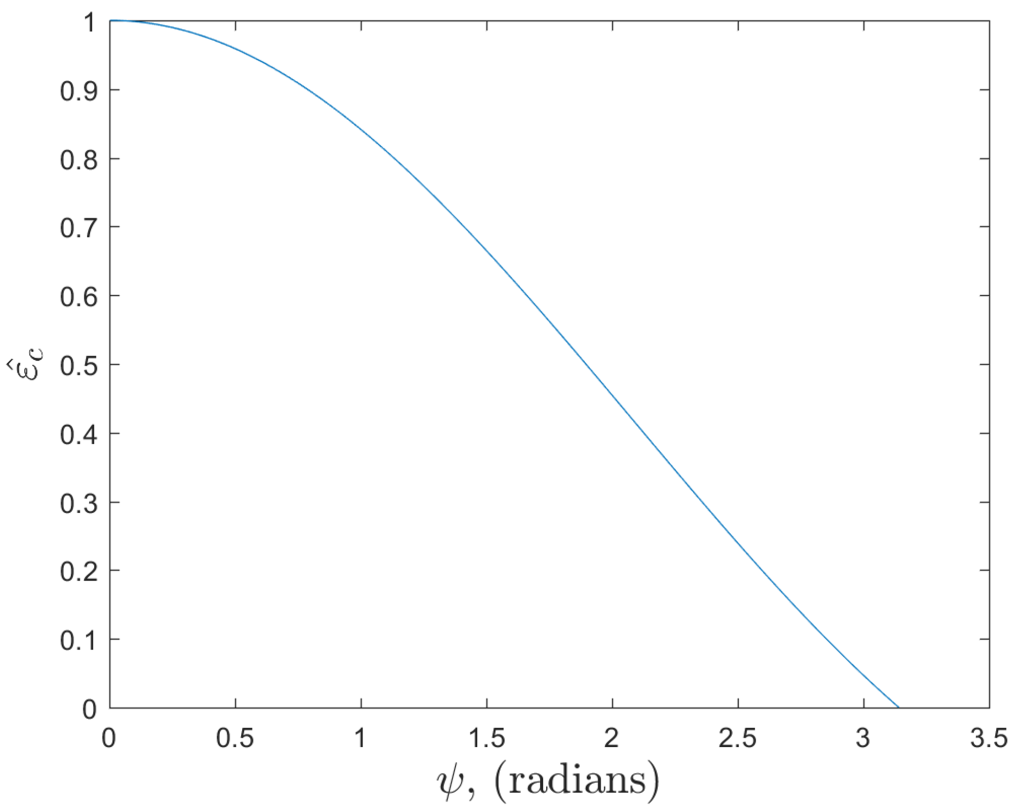
The results of these maximum angles are presented in Table 1 based on the average acceptable energy loss. Figure 3 shows the average expected energy per chip for ψ m a x ( 0 : π ] .
A second option for the distribution of the induced error is a normal distribution. This will weight more of the values closer to the mean and, depending on the variance, still allow for smaller probabilities of outliers to occur, further compounding cryptanalysis attempts. This would allow a design to possibly allow the tails of the distribution to extend beyond the 3 dB loss limit but with extremely low probabilities. The pdf of a normal distribution is defined by
f ( ψ ) = 1 2 π σ 2 e ( ψ μ ) 2 2 σ 2 ,
where μ is the mean and σ is the standard deviation of the distribution. By substituting this pdf into Equation (7), the average expected energy per chip over a normally distributed phase offset in the range of [ ψ m a x : ψ m a x ] is defined as follows:
E [ ε c ] = ε 0 2 π σ 2 2 ψ ψ m a x ψ m a x 1 2 π σ 2 e ( ϕ μ ) 2 2 σ 2 cos ϕ d ϕ ,
with a scaling factor of 2 π σ 2 2 ψ to ensure the pdf integrates to one. Finally, due to symmetry, Equation (13) can be rewritten as
E [ ε c ] = ε 0 1 ψ 0 ψ m a x e ( ϕ μ ) 2 2 σ 2 cos ϕ d ϕ .
Ideally, μ = 0 and σ would be chosen such that the design still has a large number of phase states for an acceptable average energy loss. Figure 4 shows the effects of σ on the average energy at a given angle ψ . For small values of σ , the distribution falls off quickly, allowing the average chip energy to converge to a value at which additional increases in ψ will not have a large influence. Moreover, as the variance grows larger, the curve approaches the limit of a uniform distribution, as shown in Figure 3. This is due to the fact that as σ 2 , e ( ϕ μ ) 2 2 σ 2 1 , and Equation (13) simplifies to Equation (8).
Similar to Table 1, for a uniform distribution, the maximum angle ψ m a x for a given average chip energy can be determined. However, there is no easy closed-form solution, and thus ψ m a x can be approximated through simulations, as presented in Figure 4. For smaller values of σ , only smaller acceptable losses are achievable. However, as previously mentioned, as σ increases, the values of ψ m a x approach the values of a uniform distribution (Table 1). Additional probability distributions on ψ may be chosen without loss of generality, such as the normal distribution presented in Table 2, and the pdf choice may even be made into a time-varying feature of the layered security approach.

3.2.2. Discrete Phase State Mapping

All the previous examples were carried out assuming a continuous range of values, but in reality, this TRANSEC architecture will have an integer of discretized phase-mapped states M. (A nearly continuous phase perturbation may be used without loss of generality simply by allowing the transmitter-side phase mapping of ψ to have a larger phase word resolution than the receiver phase, thereby further increasing security against an observer. The residual phase error will naturally be less than one LSB of the receiver-side representation of θ ). These phase states are illustrated in Figure 5 with M = 8 .
The total number of possible phase states changes m can be calculated based on the maximum angle of loss ψ m a x and the angle between M-ary phase mapping states M as follows:
m = 2 ψ m a x | M | + 1 .
For example, with M = 64 phase states, an acceptable average loss L = 2 dB, and ψ m a x = 1.22 radians, while m is 25, allowing for the original phase state and ± 12 possible different phase state offsets. Table 3 shows the number of possible state changes of the transmitter based on the acceptable performance loss for different values of phase-discretized M-ary PSK constellations.
Figure 6 is an example of an M-ary system with M = 64 that illustrates the number of phases states allowed by the average acceptable loss. For example, the red lines bound a 0.25 dB acceptable loss with 11 states, the yellow lines show the limit of a loss of 1 dB and includes 23 states, and the purple lines contain 39 states for an acceptable loss of 3 dB. Note that the range over which the phase perturbations may be made is quite large, and yet an acceptable average signal loss is retained.
After determining the total number of phase states, the probability of an attacker knowing the true phase value θ , given that the attacker has the correct transmitted phase ϕ , is
P ( θ | ϕ ) = 1 m
for a uniformly distributed induced phase error ψ . Therefore, it becomes a design trade-off for the number of desirable states m and the acceptable average energy loss L.

3.3. Energy per Symbol Calculations

All previous calculations were performed at the chip level. Now, the discussion will shift to spread spectrum symbol energy. The symbol energy ε s was defined in Equation (1), but due to the addition of the phase error ψ , the average expected symbol energy ε s ^ must be considered and is defined (assuming a zero mean or symmetric distribution) as follows:
ε s ^ = ε c n = 1 N cos ψ n .
The expected value of ε s ^ is defined by
E [ ε s ^ ] = ε s ^ N ε c .
As the number of chips N increases, the expected value of ε s ^ shall converge based on the acceptable loss L toward 10 L 10 . Given the fact that the individual spread spectrum symbol is composed of a large number of chips, the phase perturbations from those chips will converge toward the expected averages even within a single symbol. Thus, the convergence assumption grows more and more true as the spread ratio increases. In the context of our hardware demonstration system, N = 175 is shown to be more than sufficient for assuming this convergence.

4. Exemplary Design and Simulation Basis

4.1. Proof-of-Concept Model

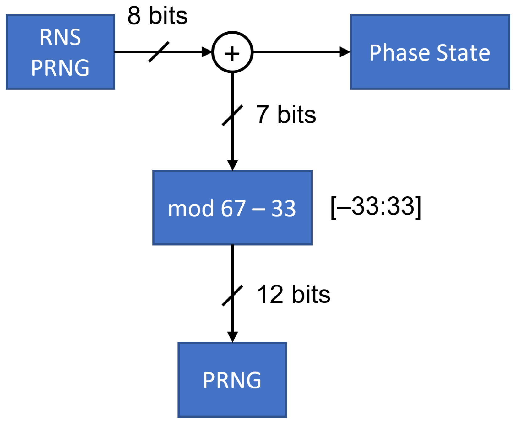
In developing a hardware prototype to validate the efficacy of this semi-coherent TRANSEC method, an exemplary design of the induced error approach is shown in Figure 7. In this diagram, the actual bulk chip phase state is determined from an RNS-based PRNG as an eight-bit value representing a single phase on a M = 256 phase constellation. Additional details on this high-order PSK signaling (HOPS) modulation scheme and the hardware methods are described in [43,58]. Moreover, any alternative method for generating a polyphase spreading code can be used without limitation. Our assumption here is that the RNS PRNG is interpreted as a value on [ 1 , 1 ) , mapped according to
Bulk Chip Phase = ( RNS PRNG Output ) + 1 2 128 π
For the perturbation phase additions, a second unsynchronized PRNG is used to create a 12 bit value. This 12 bit error is then reduced via modulo to m, where m = 67 allows an average error loss of 0.5 dB. Choosing different values of m according to Table 3 will enable different phase deviations. This chosen reduction only allows a new range of 67 values, which will not be a perfect uniform distribution. However, it will be approximately uniform due to the large amount of aliasing, as described in [59]. That intermediate value is mapped to the correct phase state range by subtracting 33 ( m 2 1 ) to map the error range to a zero mean [−33:33], which is represented by seven signed bits. Finally, the true phase 8 bit value and the 7 bit error value are added together (accounting for overflow) to produce the TRANSEC modulation phase state value.
This process is a relatively simple addition to the current conception of polyphase spread spectrum communication systems [43,58], with no direct effect on the user data processing, the spreading ratio, the subsequent baseband signal processing, or any of the remaining spreading operations. Moreover, in noting the relative magnitudes of the two phase values, it can be seen that the bulk phase value dominates the perturbation phase contribution, consistent with the phase diagram of Figure 6.

4.2. Simulation Results

The design shown in Figure 7 was modeled in MATLAB R2023b to determine the performance loss at different numbers of phase states m. A total of 10,000,000 uniformly distributed samples were used in the simulation, and the results are shown in Table 4. These results reinforce the values of m shown in Table 3. For m = 67 , the percentage of samples that did not have a phase offset (which represents an attacker guessing the actual phase) was 0.0149 1 67 , as expected from Equation (16). Similar results were found for the other values of M and m.
To evaluate whether the specific distribution of phases has an effect on the simulated results, other distributions were evaluated. Again, 10,000,000 chips were simulated for a given acceptable performance loss with phase errors with a normal distribution. For M = 256 and σ = π 2 , the results are shown in Table 5. The differences between the expected and calculated results were primarily due to the differences between the continuous and discrete chip phases, as discussed in Section 3.2.
One of the benefits of the normal distribution for the semi-coherent TRANSEC addition in Table 5 over that of the uniform distribution in Table 4 is that the absolute spread is substantially higher, giving greater difficulty reigning in the range of potential phase states. Most cryptographic processes such as PRNGs are based on uniform distributed calculations, and thus mixing distributions leads to practical challenges in streamlining reverse engineering attempts, which is good for system security.

4.3. Symbol Energy Calculations

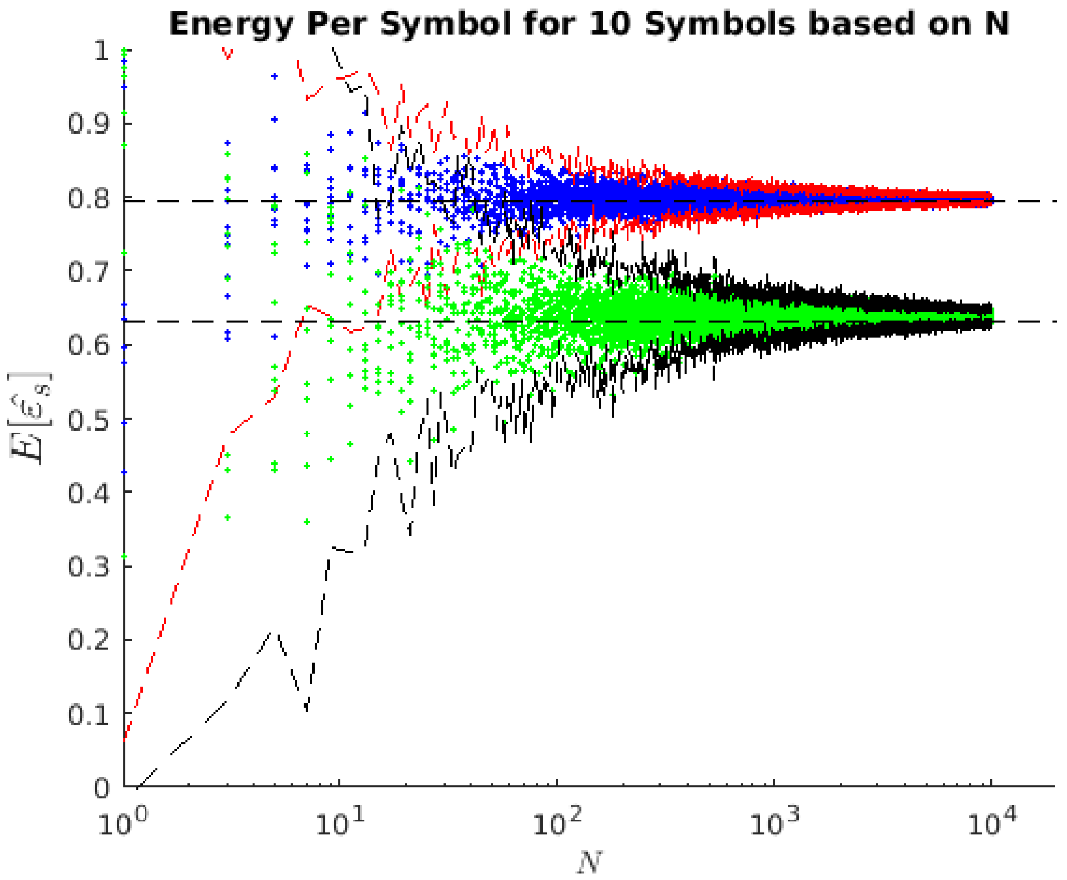
Average symbol energy per chip ε s ^ calculations were performed in MATLAB for 10 symbols created with increasing values of chips N with both uniform and normal distributions, with the results presented in Figure 8. The blue dots represent the uniformly distributed errors, and the green dots are the normally distributed phase errors. As is clearly visible, as the number of chips per symbol increased, the values converged toward the expected values, 10 L 10 , due to the law of large numbers. Both of the distributions are bounded in the figure by ± 3 σ as the red and black lines for each respective distribution.

5. Implementation Results

To fully validate the approach in hardware, the proposed design was implemented on an Intel Arria 10 System-on-a-Chip (SoC) field-programmable gate array (FPGA) development kit. This implementation builds on previous work with the HOPS waveform [43,58] using the exemplary design presented in Section 4, with the caveat that the PRNG used to induce a phase error was allowed to be reseeded between each frame transmission. In the process, the underlying spreading code generated via the RNS-based PRNG remained static, yet each transmission was made up from an entirely different sequence of I and Q samples due to the phase deviations. Any observations of the resulting RF spectrum would differ even at high SNRs, further complicating any attempt to reverse engineer the spreading code or RNS-based PRNG process [45], resulting in a pseudo-time-evolving spread spectrum signal without the need for any computationally intense processing that accompanies such waveforms.
The 10 MHz instantaneous bandwidth HOPS signals featured an eight-symbol preamble for signal detection and acquisition, from which the static phase offset and frequency offset were derived. Each correlation operated at a 20 MHz clock rate on a signal that was received at two times the baseband clock rate. When the correlation magnitude, which was calculated for each clock cycle, exceeded a pre-calculated threshold (based on a moving average of the incoming signal samples), the received signal was downsampled by a factor of two and input into the demodulator. Given the short lengths of the associated packet-based signals (from 8 up to 128 symbols), symbol timing and frequency tracking loops were not used by the implementation described in this paper. Demodulation consisted of a straightforward despreading operation that was time-aligned to the incoming signal. The end of each packet was determined by comparing the sequences of eight despread symbol magnitudes to the correlation magnitude that triggered demodulation. When the symbol magnitudes dropped below a threshold, demodulation had concluded. FEC decoding of the despread symbols was required before handing over the received packet for further processing in software.
In designing a real-world communications system, we are interested in the effects of the induced phase error on the ability of the receiver to successfully detect and decode packets of information bits rather than the individual symbols. The performance loss due to decreased symbol energies must be looked at in terms of the aggregate of all symbols in the transmitted data packet. Any performance improvement attributed to FEC techniques, such as the use of polar codes in the HOPS design [58], should also be considered. For the HOPS implementation, five different FEC modes were employed with varying coding gains across packet lengths from 16 up to 256 bits, namely PC(16,12), PC(32,27), PC(64,52), PC(128,114), and PC(256, 224).
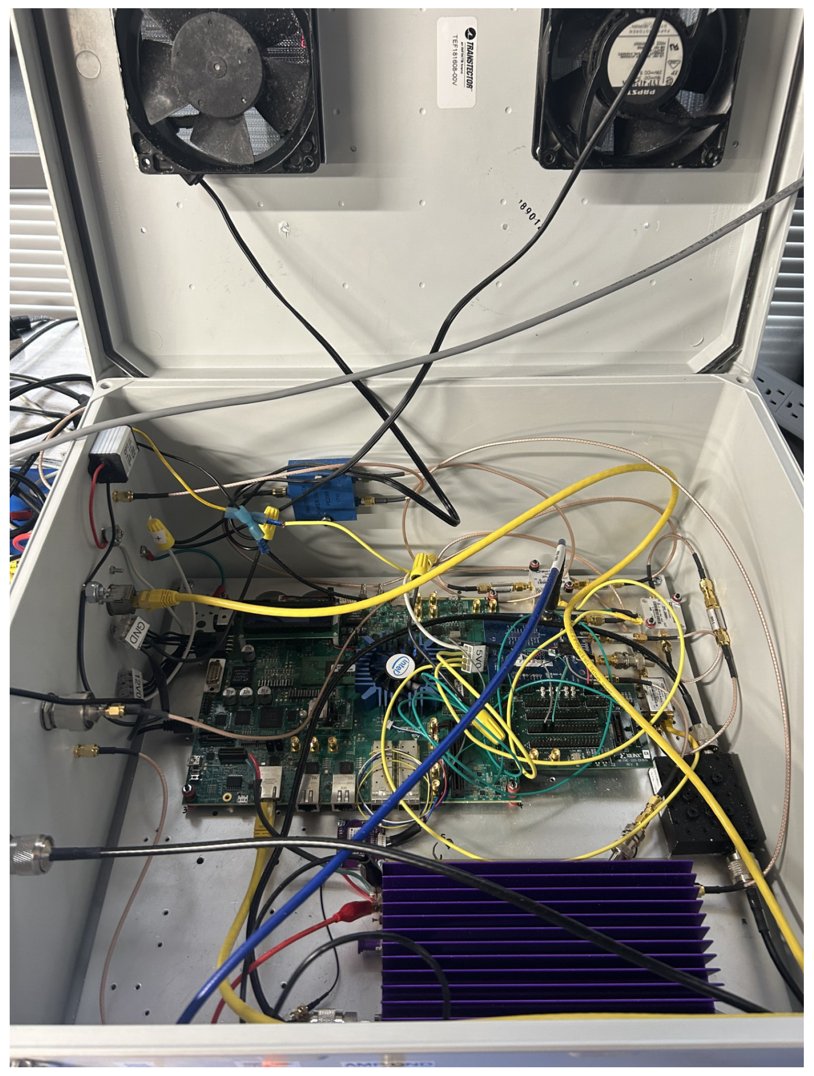
Hardware validation tests consisted of a point-to-point transmission of known data packets from one Arria 10 development kit (see Figure 9) to another over a cabled test set-up. A Keysight (Santa Rosa, CA, USA) N5183B MXG signal generator was used to inject additive white Gaussian noise (AWGN) into the test set-up to produce a known background noise floor for SNR calibrations. Although most of the hardware tests discussed in this paper were automated, there was an initial measurement of the SNR on a (Santa Rosa, CA, USA) N9040B UXA signal analyzer performed by sending a continuous stream of data packets from the transmitting Arria 10 device to the receiving device, where measurements would be made. Taking this measurement at an extremely high SNR (approximately 30 dB above the background noise) before introducing 30–40 dB of attenuation to the signal allowed for a starting HOPS SNR to be calibrated. Subsequent adjustments to the SNR were made relative to this initial value.
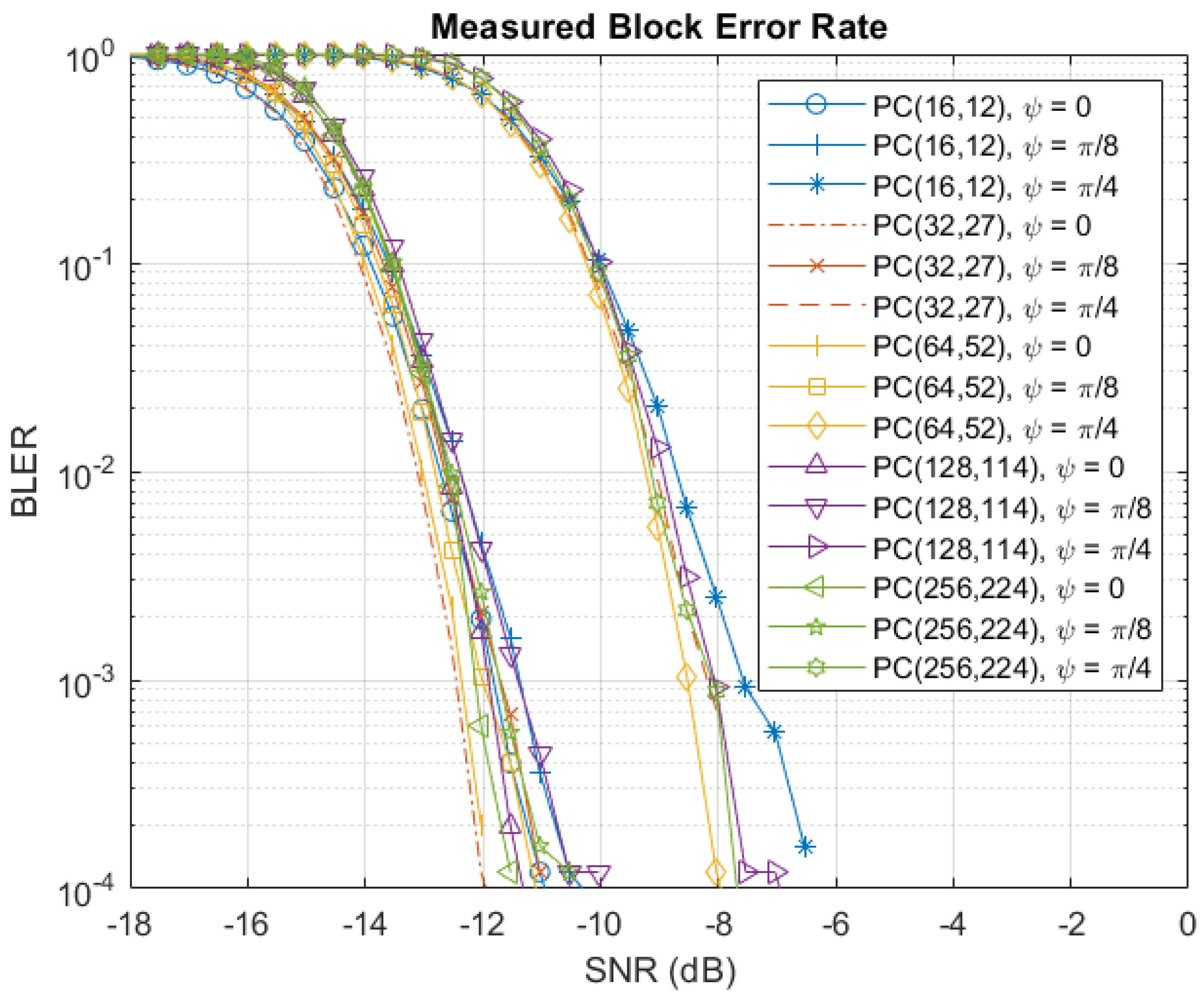
Measurements of the block error rate (BLER) were performed as a function of the SNR, and the results are shown in Figure 10. To provide a baseline for comparison, ψ = 0 represents the HOPS design without any induced phase error, while ψ = π / 8 and ψ = π / 4 provide a reference for BLER degradation in the proposed design. As expected, the phase error inducement degraded the BLER, with a significant impairment of approximately 3.5–4 dB in the ψ = π / 4 case. The degradation from the ψ = π / 8 phase error was less obvious at first glance.
Taking a closer look at the hardware measurements provided in Figure 10, Figure 11 shows a zoomed-in view of the results centered at BLER = 10 2 to compare the baseline design ( ψ = 0 ) to the ψ = π / 8 design, while Figure 12 offers the same comparison with the ψ = π / 4 design. The BLER = 10 2 point is effectively the operating point of the signal (one retransmission was expected per each 100 blocks). Although in situations where limiting the time on the air is important to protecting overall transmission security, designers may favor a lower BLER to further limit retransmissions. While the ψ = π / 8 phase error degradation varied slightly, depending on the specific message type in Figure 11, the degradation was to the order of 0.1–0.5 dB.
When considering the symbol energy loss calculations and the simulated results in Section 3, a BLER degradation of 0.5 dB and 4 dB for ψ = π / 8 and ψ = π / 4 , respectively, were validated as accurate in a live hardware communications system. For the implemented system, ψ = π / 8 offered a good trade in improved security at the cost of minor performance degradations, resulting in an operating SNR of the signal that was altogether similar to the unperturbed baseline design. It should also be noted that the hardware resource utilization counts were marginally increased in the proposed design. In Table 6, Design A refers to the unmodified base design, while Design B incorporated the proposed technique. An increase in adaptive logic modules (ALMs) of 1.6% and adaptive look-up tables (ALUTs) of 0.9% is an easy decision considering the improved security of the design. The M20K memory block increase of 14.8% was due to the fact that 16 separate read-only memories (ROMs) were instantiated within the PRNG; this increase can be significantly reduced via the incorporation of clock folding or inclusion in a more efficient implementation as distributed logic.
These hardware validation results are a strong indication that the proposed technique stands out from earlier TRANSEC approaches through its unique integration of noise injection directly into the phase mapping process of a spread spectrum signal, aimed specifically at low-power IoT systems. A comparison of PHY layer-based TRANSEC approaches and the literature is presented in Table 7. Unlike traditional TRANSEC techniques like DSSS or frequency-hopping spread spectrum (FHSS), which often assume generous computational resources or robust synchronization support, this method is specifically engineered for energy-constrained, embedded IoT devices. It addresses the critical gap where traditional PHY layer security is too costly or complex. In comparison with waveform agility or co-channel watermarking techniques, which require full coherent detection and synchronized keys, this approach trades off correlation performance for additional security via semi-coherent processing, making it highly viable in practical noisy, low-power networks. Lastly, compared with recent techniques such as channel-aware modulation [60] or waveform morphing, which rely on accurate channel state information or advanced signal processing, this approach is lightweight and easy to integrate into existing PSK spread spectrum systems without significant redesign.

6. Conclusions

This paper examined a low-power technique for obfuscating the actual instantaneous phase of each chip within a spread spectrum communication system with a small induced phase error. Both uniform and normal error distributions were considered, but this design is largely agnostic in distribution, while normal distributed TRANSEC injection offers better anticipated protections from reverse engineering. The calculations and hardware validations proven within a live polyphase spread spectrum system indicate that significant protections against reverse engineering of system state values is achievable even at relatively low performance losses, based on the number of states of the constellation used. The techniques presented are most relevant to high-order phase constellations and thus will have limited utility in DSSS communications. The results presented show that as the number of chips per spread spectrum symbol increased, the average energy per symbol quickly converged toward the expected value. Extending the analytical and simulated results to an implemented design with variable length packets using the HOPS waveform further validated the feasibility of this approach. For 256-ary PSK constellations, an induced phase error of ψ = π / 8 resulted in an approximate BLER degradation of ≤0.5 dB, while a phase error of ψ = π / 4 led to ≤4 dB of degradation. The former is a quite acceptable trade of minor performance loss for overall security enhancement, while the latter demonstrates an upper bound for phase perturbations impairing performance of the intended link. In both cases, a hardware resource utilization increase of less than 2% confirmed the expectation of a negligible hardware cost and therefore a low-power design.
The approach presented in this paper uses a fixed level of phase distortion regardless of the channel conditions, adversary capabilities, or operational environments. Future work may integrate an adaptive mechanism to scale the amount of phase obfuscation injected into the signal. Additionally, future work aims to combine this and other low-power security approaches into an IoT system security architecture. Similarly, research to determine the viability of incorporating the technique into existing low-power wireless standards (e.g., IEEE 802.15.4, or Bluetooth Low Energy) without breaking protocol-level expectations is deemed worthwhile.

Author Contributions

Conceptualization, A.J.M.; methodology, J.M. and M.F.; validation, M.F.; resources, A.J.M.; writing—original draft preparation, J.M. and M.F.; writing—review and editing, A.J.M.; supervision, A.J.M. All authors have read and agreed to the published version of the manuscript.

Funding

This research received no external funding.

Data Availability Statement

The data for this hardware validation was based on live measurements of a proprietary communication system and published in its summary form with permission from the owner.

Conflicts of Interest

The authors declare no conflicts of interest.

References

  1. Vasseur, J.P.; Dunkels, A. Interconnecting Smart Objects with IP: The Next Internet; Morgan Kaufmann Publishers Inc.: San Francisco, CA, USA, 2010. [Google Scholar]
  2. Shannon, C.E. Communication theory of secrecy systems. Bell Labs Tech. J. 1949, 28, 656–715. [Google Scholar] [CrossRef]
  3. Kenyeres, M.; Kenyeres, J.; Hassankhani Dolatabadi, S. Distributed Consensus Gossip-Based Data Fusion for Suppressing Incorrect Sensor Readings in Wireless Sensor Networks. J. Low Power Electron. Appl. 2025, 15, 6. [Google Scholar] [CrossRef]
  4. Su, X.; Wang, Z.; Liu, X.; Choi, C.; Choi, D. Study to Improve Security for IoT Smart Device Controller: Drawbacks and Countermeasures. Secur. Commun. Netw. 2018, 2018, 4296934. [Google Scholar] [CrossRef]
  5. Soto-Cruz, J.; Ruiz-Ibarra, E.; Vázquez-Castillo, J.; Espinoza-Ruiz, A.; Castillo-Atoche, A.; Mass-Sanchez, J. A Survey of Efficient Lightweight Cryptography for Power-Constrained Microcontrollers. Technologies 2025, 13, 3. [Google Scholar] [CrossRef]
  6. Gazziro, M.; Carmo, J.P. Power Consumption Efficiency of Encryption Schemes for RFID. Chips 2024, 3, 216–228. [Google Scholar] [CrossRef]
  7. Sabbry, N.H.; Levina, A.B. An Optimized Point Multiplication Strategy in Elliptic Curve Cryptography for Resource-Constrained Devices. Mathematics 2024, 12, 881. [Google Scholar] [CrossRef]
  8. Yang, Y.; Zhou, J.; Wang, F.; Shi, C. An LPI design for secure burst communication systems. In Proceedings of the 2014 IEEE China Summit & International Conference on Signal and Information Processing (ChinaSIP), Xian, China, 9–13 July 2014; pp. 631–635. [Google Scholar] [CrossRef]
  9. Shi, C.; Wang, F.; Salous, S.; Zhou, J. Optimal Power Allocation Strategy in a Joint Bistatic Radar and Communication System Based on Low Probability of Intercept. Sensors 2017, 17, 2731. [Google Scholar] [CrossRef]
  10. Li, L.; Lv, J.; Ma, X.; Han, Y.; Feng, J. Design of Low Probability Detection Signal with Application to Physical Layer Security. Electronics 2023, 12, 1075. [Google Scholar] [CrossRef]
  11. Pickholtz, R.; Schilling, D.; Milstein, L. Theory of Spread-Spectrum Communications—A Tutorial. IEEE Trans. Commun. 1982, 30, 855–884. [Google Scholar] [CrossRef]
  12. Di Benedetto, M.G.; Vojcic, B.R. Ultra wide band wireless communications: A tutorial. J. Commun. Netw. 2003, 5, 290–302. [Google Scholar] [CrossRef]
  13. Harvey, B.; Howard, D.; Barnhart, E.; Loso, F.; Staba, J. An analysis of MMW wireless LANs for LPI/AJ command post communications. In Proceedings of the MILCOM’93—IEEE Military Communications Conference, Boston, MA, USA, 11–14 October 1993; Volume 2, pp. 580–584. [Google Scholar] [CrossRef]
  14. Yip, L. Performance Assessment of LPD/LPI Satellite Communication Systems. In Proceedings of the 2023 IEEE Aerospace Conference, Big Sky, MO, USA, 4–11 March 2023; pp. 1–7. [Google Scholar] [CrossRef]
  15. Winarno, A.; Sari, R.F. A Novel Secure End-to-End IoT Communication Scheme Using Lightweight Cryptography Based on Block Cipher. Appl. Sci. 2022, 12, 8817. [Google Scholar] [CrossRef]
  16. Rodriguez Bejarano, J.M.; Yun, A.; De La Cuesta, B. Security in IP satellite networks: COMSEC and TRANSEC integration aspects. In Proceedings of the 2012 6th Advanced Satellite Multimedia Systems Conference (ASMS) and 12th Signal Processing for Space Communications Workshop (SPSC), Vigo, Spain, 5–7 September 2012; pp. 281–288. [Google Scholar] [CrossRef]
  17. Wyner, A.D. The Wire-Tap Channel. Bell Syst. Tech. J. 1975, 54, 1355–1387. [Google Scholar] [CrossRef]
  18. Maurer, U.M. Secret key agreement by public discussion from common information. IEEE Trans. Inf. Theory 1993, 39, 733–742. [Google Scholar] [CrossRef]
  19. Hero, A.O. Secure space-time communication. IEEE Trans. Inf. Theory 2003, 49, 3235–3249. [Google Scholar] [CrossRef]
  20. Thangaraj, A.; Dihidar, S.; Calderbank, A.R.; McLaughlin, S.; Merolla, J.M. Capacity achieving codes for the wiretap channel with applications to quantum key distribution. arXiv 2004, arXiv:0411003. [Google Scholar]
  21. Bloch, M.; Barros, J.; Rodrigues, M.R.D.; McLaughlin, S.W. Wireless Information-Theoretic Security. IEEE Trans. Inf. Theory 2008, 54, 2515–2534. [Google Scholar] [CrossRef]
  22. Alhamarneh, R.A.; Mahinderjit Singh, M. Strengthening Internet of Things Security: Surveying Physical Unclonable Functions for Authentication, Communication Protocols, Challenges, and Applications. Appl. Sci. 2024, 14, 1700. [Google Scholar] [CrossRef]
  23. Wu, T.Y.; Kong, F.; Wang, L.; Chen, Y.C.; Kumari, S.; Pan, J.S. Toward Smart Home Authentication Using PUF and Edge-Computing Paradigm. Sensors 2022, 22, 9174. [Google Scholar] [CrossRef]
  24. Zou, Y.; Zhu, J.; Wang, X.; Leung, V.C.M. Improving physical-layer security in wireless communications using diversity techniques. IEEE Netw. 2015, 29, 42–48. [Google Scholar] [CrossRef]
  25. Efstathiou, D.; Papadopoulos, G.D.; Tsipouridou, D.; Pavlidou, F.N. Enhancement of transmission security for OFDM based systems. In Proceedings of the 2017 IEEE Symposium on Computers and Communications (ISCC), Heraklion, Greece, 3–6 July 2017; pp. 546–551. [Google Scholar] [CrossRef]
  26. Elmasry, G.; Corwin, P. Hiding the RF Signal Signature in Tactical 5G. In Proceedings of the MILCOM 2021—2021 IEEE Military Communications Conference (MILCOM), San Diego, CA, USA, 29 November–2 December 2021; pp. 733–738. [Google Scholar] [CrossRef]
  27. Sperandio, C.; Flikkema, P.G. Wireless physical-layer security via transmit precoding over dispersive channels: Optimum linear eavesdropping. In Proceedings of the MILCOM 2002, Anaheim, CA, USA, 7–10 October 2002; Volume 2, pp. 1113–1117. [Google Scholar] [CrossRef]
  28. Peng, H.; Xie, K.; Zou, W. Research on an Enhanced Multimodal Network for Specific Emitter Identification. Electronics 2024, 13, 651. [Google Scholar] [CrossRef]
  29. Zhang, S.; Liu, F.; Huang, Y.; Meng, X. Adaptive Detection of Direct-Sequence Spread-Spectrum Signals Based on Knowledge-Enhanced Compressive Measurements and Artificial Neural Networks. Sensors 2021, 21, 2538. [Google Scholar] [CrossRef] [PubMed]
  30. McGinthy, J.M.; Michaels, A.J. Semi-Coherent Transmission Security for Low Power IoT Devices. In Proceedings of the 2018 IEEE International Conference on Internet of Things (iThings-2018), Halifax, NS, Canada, 30 July–3 August 2018. [Google Scholar]
  31. Xu, L.; Liu, X.; Zhang, Y. Blind Estimation of Spreading Code Sequence of QPSK-DSSS Signal Based on Fast-ICA. Information 2023, 14, 112. [Google Scholar] [CrossRef]
  32. Grzesiak, K.; Piotrowski, Z. From Constellation Dithering to NOMA Multiple Access: Security in Wireless Systems. Sensors 2021, 21, 2752. [Google Scholar] [CrossRef] [PubMed]
  33. Stallings, W. Cryptography and Network Security: Principles and Practice, 7th ed.; Pearson Education: London, UK, 2017. [Google Scholar]
  34. Nguyen, H.; Hoang, T.; Tran, L. Efficient Hardware Implementation of Elliptic-Curve Diffie–Hellman Ephemeral on Curve25519. Electronics 2023, 12, 4480. [Google Scholar] [CrossRef]
  35. Zeghid, M.; Sghaier, A.; Ahmed, H.Y.; Abdalla, O.A. Power/Area-Efficient ECC Processor Implementation for Resource-Constrained Devices. Electronics 2023, 12, 4110. [Google Scholar] [CrossRef]
  36. Miller, F.P.; Vandome, A.F.; McBrewster, J. Advanced Encryption Standard; Alpha Press: Halifax, UK, 2009. [Google Scholar]
  37. Sklar, B. Digital Communications; Prentice Hall: Upper Saddle River, NJ, USA, 2001; Volume 2. [Google Scholar]
  38. Viterbi, A.J. CDMA: Principles of Spread Spectrum Communication; Addison-Wesley: Boston, MA, USA, 1995; Volume 122. [Google Scholar]
  39. Braasch, M.S.; van Dierendonck, A.J. GPS receiver architectures and measurements. Proc. IEEE 1999, 87, 48–64. [Google Scholar] [CrossRef]
  40. Kaddoum, G.; Gagnon, G.; Gagnon, F. Spread spectrum communication system with sequence synchronization unit using chaotic symbolic dynamics modulation. Int. J. Bifurc. Chaos 2013, 23, 1350019. [Google Scholar] [CrossRef]
  41. IEEE Std 802.11-2012 (Revision of IEEE Std 802.11-2007); IEEE Standard for Information Technology–Telecommunications and Information Exchange Between Systems Local and Metropolitan Area Networks–Specific Requirements Part 11: Wireless LAN Medium Access Control (MAC) and Physical Layer (PHY) Specifications. IEEE Standards Association: New York, NY, USA, 2012; pp. 1–2793. [CrossRef]
  42. Garg, V.K. IS-95 CDMA and CDMA2000: Cellular/PCS Systems Implementation; Pearson Education: London, UK, 1999. [Google Scholar]
  43. Michaels, A.J. High-Order PSK Signaling (HOPS) Techniques for Low-Power Spread Spectrum Communications. In Proceedings of the 2018 IEEE 19th International Symposium on “A World of Wireless, Mobile and Multimedia Networks” (WoWMoM), Chania, Greece, 12–15 June 2018; pp. 1–7. [Google Scholar] [CrossRef]
  44. Karimov, T.; Rybin, V.; Kolev, G.; Rodionova, E.; Butusov, D. Chaotic Communication System with Symmetry-Based Modulation. Appl. Sci. 2021, 11, 3698. [Google Scholar] [CrossRef]
  45. Vennos, A.; George, K.; Michaels, A. Attacks and Defenses for Single-Stage Residue Number System PRNGs. IoT 2021, 2, 375–400. [Google Scholar] [CrossRef]
  46. Liu, C.; Ding, L.; Ding, Q. Research about the Characteristics of Chaotic Systems Based on Multi-Scale Entropy. Entropy 2019, 21, 663. [Google Scholar] [CrossRef]
  47. Spread Spectrum Satcom Hacking: Attacking the Globalstar Simplex Data Service. 2015. Available online: https://www.blackhat.com/docs/us-15/materials/us-15-Moore-Spread-Spectrum-Satcom-Hacking-Attacking-The-GlobalStar-Simplex-Data-Service.pdf (accessed on 19 March 2025).
  48. Bras-Amorós, M.; O’Sullivan, M.E. The Symmetric Key Equation for Reed–Solomon Codes and a New Perspective on the Berlekamp–Massey Algorithm. Symmetry 2019, 11, 1357. [Google Scholar] [CrossRef]
  49. Lee, D.H.; Lee, I.Y. A Lightweight Authentication and Key Agreement Schemes for IoT Environments. Sensors 2020, 20, 5350. [Google Scholar] [CrossRef]
  50. Alshammari, F.; Ong, L.; Tan, J.Y. An Optimal Secure Key Distribution Scheme for Internet of Things Devices in Multi-Session Network Communications. Electronics 2024, 13, 4951. [Google Scholar] [CrossRef]
  51. Wold, K.; Petrovic, S. Optimizing Speed of a True Random Number Generator in FPGA by Spectral Analysis. In Proceedings of the 2009 Fourth International Conference on Computer Sciences and Convergence Information Technology, Seoul, Republic of Korea, 24–26 November 2009; pp. 1105–1110. [Google Scholar] [CrossRef]
  52. Wanna, P.; Wongthanavasu, S. An Efficient Cellular Automata-Based Classifier with Variance Decision Table. Appl. Sci. 2023, 13, 4346. [Google Scholar] [CrossRef]
  53. Stoller, S.; Campbell, K.A. Demonstration of Three True Random Number Generator Circuits Using Memristor Created Entropy and Commercial Off-the-Shelf Components. Entropy 2021, 23, 371. [Google Scholar] [CrossRef] [PubMed]
  54. Michaels, A.J. A maximal entropy digital chaotic circuit. In Proceedings of the Circuits and Systems (ISCAS), 2011 IEEE International Symposium, Rio de Janeiro, Brazil, 15–18 May 2011; pp. 717–720. [Google Scholar]
  55. Zeng, K.; Yang, C.H.; Wei, D.Y.; Rao, T.R.N. Pseudorandom bit generators in stream-cipher cryptography. Computer 1991, 24, 8–17. [Google Scholar] [CrossRef]
  56. Blum, L.; Blum, M.; Shub, M. A Simple Unpredictable Pseudo-Random Number Generator. SIAM J. Comput. 1986, 15, 364–383. [Google Scholar] [CrossRef]
  57. Barker, E.B.; Kelsey, J.M. SP 800-90A Rev. 1. Recommendation for Random Number Generation Using Deterministic Random Bit Generators; Technical report; National Institute of Standards & Technology: Gaithersburg, MD, USA, 2012. [Google Scholar]
  58. Fletcher, M.; Paulz, E.; Ridge, D.; Michaels, A.J. Low-Latency Wireless Network Extension for Industrial Internet of Things. Sensors 2024, 24, 2113. [Google Scholar] [CrossRef]
  59. McGinthy, J.M.; Michaels, A.J. Session Key Derivation for Low Power IoT Devices. In Proceedings of the 2018 IEEE 4th International Conference on Big Data Security on Cloud (bigdatasecurity), IEEE International Conference on High Performance and Smart Computing (HPSC), and IEEE International Conference on Intelligent Data and Security (IDS), Omaha, NE, USA, 3–5 May 2018. [Google Scholar]
  60. Hamamreh, J.M.; Furqan, H.M.; Arslan, H. Classifications and Applications of Physical Layer Security Techniques for Confidentiality: A Comprehensive Survey. IEEE Commun. Surv. Tutor. 2019, 21, 1773–1828. [Google Scholar] [CrossRef]
  61. Shiu, Y.S.; Chang, S.Y.; Wu, H.C.; Huang, S.C.H.; Chen, H.H. Physical layer security in wireless networks: A tutorial. IEEE Wirel. Commun. 2011, 18, 66–74. [Google Scholar] [CrossRef]
  62. Fletcher, M. Enhanced Implementations for Arbitrary-Phase Spread Spectrum Waveforms. Master’s Thesis, Virginia Polytechnic Institute and State University, Blacksburg, VA, USA, 2019. [Google Scholar]
  63. Michaels, A.J.; Palukuru, V.S.S.; Fletcher, M.J.; Henshaw, C.; Williams, S.; Krauss, T.; Lawlis, J.; Moore, J.J. CAN Bus Message Authentication via Co-Channel RF Watermark. IEEE Trans. Veh. Technol. 2022, 71, 3670–3686. [Google Scholar] [CrossRef]
  64. Zhao, Z.; Zhou, N.; Zheng, H.; Qin, P.; Yi, L. Security Enhancement for Noise Aggregation in DVB-S2 Systems. In Proceedings of the Signal and Information Processing, Networking and Computers, Ji’nan, China, 13–17 September 2021; Sun, J., Wang, Y., Huo, M., Xu, L., Eds.; Springer Nature: Singapore, 2023; pp. 326–334. [Google Scholar]
  65. Himanshi; Garg, A. Comparative Study of Physical Layer Secure Key Generation for Wireless Networks. In Proceedings of the 2024 IEEE Region 10 Symposium (TENSYMP), New Delhi, India, 27–29 September 2024; pp. 1–6. [Google Scholar] [CrossRef]
  66. Jeung, J.; Jeong, S.; Lim, J. Adaptive rapid channel-hopping scheme mitigating smart jammer attacks in secure WLAN. In Proceedings of the 2011—MILCOM 2011 Military Communications Conference, Baltimore, MD, USA, 7–10 November 2011; pp. 1231–1236. [Google Scholar] [CrossRef]
  67. Fraga-Lamas, P.; Castedo-Ribas, L.; Morales-Méndez, A.; Camas-Albar, J.M. Evolving military broadband wireless communication systems: WiMAX, LTE and WLAN. In Proceedings of the 2016 International Conference on Military Communications and Information Systems (ICMCIS), Brussels, Belgium, 23–24 May 2016; pp. 1–8. [Google Scholar] [CrossRef]
  68. Shahriar, C.; La Pan, M.; Lichtman, M.; Clancy, T.C.; McGwier, R.; Tandon, R.; Sodagari, S.; Reed, J.H. PHY-Layer Resiliency in OFDM Communications: A Tutorial. IEEE Commun. Surv. Tutor. 2015, 17, 292–314. [Google Scholar] [CrossRef]
  69. Mcginthy, J.M.; Michaels, A.J. Secure Industrial Internet of Things Critical Infrastructure Node Design. IEEE Internet Things J. 2019, 6, 8021–8037. [Google Scholar] [CrossRef]
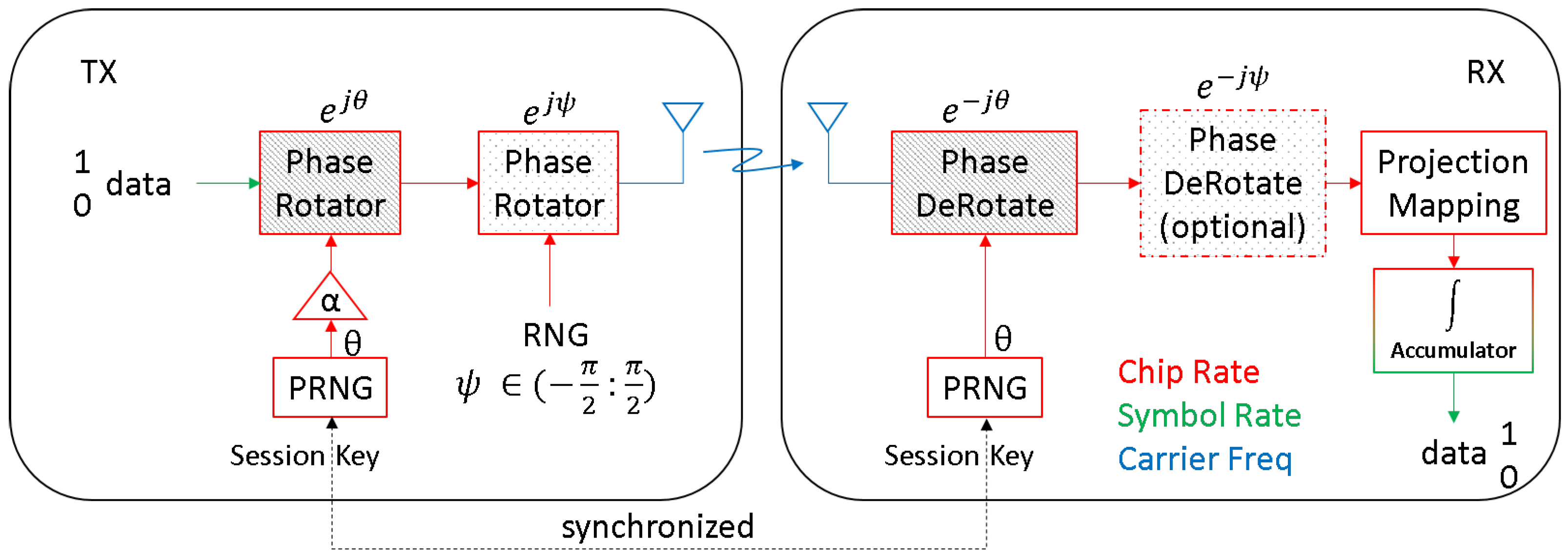
Figure 1. Conceptual view of baseband phase rotation with induced error ψ .
Information 16 00773 g001
Figure 2. Illustration of phase angle error ψ caused by the addition of a small induced error for a fixed-phase mapped angle θ .
Information 16 00773 g002
Figure 3. Average expected normalized energy per chip for a range bounded by a uniformly distributed range of [ ψ : ψ ] .
Information 16 00773 g003
Figure 4. Average expected normalized energy per chip for a range bounded by a normally distributed range of | ψ | ( 0 : π ] at different values of σ .
Information 16 00773 g004
Figure 5. Phase mapping example.
Information 16 00773 g005
Figure 6. Example of 64-ary phase states bounded by the average acceptable loss. Each blue dot represents a discrete phase error that can be added to the true phase. The red, yellow, and purple lines show bounds based on the acceptable performance loss.
Information 16 00773 g006
Figure 7. Design example with M = 256 , L = 0.5 dB, and m = 67 .
Information 16 00773 g007
Figure 8. Average expected energy per symbol for 10 symbols based on the number of chips N. Blue dots represent symbols created with uniformly distributed chip phase errors with M = 256 and m = 93 and an expected energy per chip loss of 1 dB. The green dots represent symbols with normally distributed chip phase errors with the parameters M = 256 , σ = π 2 , and m = 141 , with an expected energy per chip loss of 2 dB. Both simulations converged toward 10 L 10 based on their respective values of L.
Information 16 00773 g008
Figure 9. One of the Arria 10 SoC FPGA development boards housed in an integrated box along with the associated power amplifiers (PAs), low-noise amplifiers (LNAs), voltage distribution network, and other miscellaneous equipment.
Information 16 00773 g009
Figure 10. Measured block error rate (BLER) results for the implemented HOPS system, showing the baseline design performance with accompanying SNR curves for ψ = π / 8 and ψ = π / 4 .
Information 16 00773 g010
Figure 11. Zoomed-in view of the measured results at BLER = 10 3 , highlighting the degradations for ψ = π / 8 .
Information 16 00773 g011
Figure 12. Zoomed-in view of the measured results at BLER = 10 3 , highlighting the degradations for ψ = π / 4 .
Information 16 00773 g012
Table 1. Maximum phase angle offset based on expected average energy loss.
Loss (dB) ψ max (radians)
0.1 0.3709
0.25 0.5843
0.5 0.822
1 1.149
2 1.585
3 1.893
Table 2. Maximum phase angle offset based on expected average energy loss for a normal distribution.
σ
Loss (dB) π 8 π 4 π 2 8 π
0.10.3980.3780.3730.371
0.250.7520.6090.5890.5855
0.5-0.8910.830.82
1-1.481.1971.156
2--1.7331.591
3--2.2071.899
Table 3. Number of possible phase states based on ψ m a x with uniform distribution.
M-Ary Phase Mapping
Loss (dB) 8 16 64 256 216
0.1117317745
0.2513114712,189
0.535176717,137
135239323,949
2593312933,063
3593915539,541
Table 4. Simulation results of 256-ary phase with uniform distribution.
mExpected
Average Loss
Calculated
Average Loss
310.1 dB0.1053 dB
470.25 dB0.2440 dB
670.5 dB0.5021 dB
931 dB0.9888 dB
1292 dB1.9797 dB
1553 dB3.0493 dB
Table 5. Simulation results of 256-ary phase with normal distribution ( σ = π 2 ).
mExpected
Average Loss
Calculated
Average Loss
310.1 dB0.0922 dB
470.25 dB0.2207 dB
670.5 dB0.4568 dB
971 dB0.9565 dB
1412 dB1.9525 dB
1793 dB2.9468 dB
Table 6. Hardware resource utilization on Intel Arria 10 SoC FPGA.
ALMsALUTsRegistersMemory BitsM20Ks
Design A91,418.6128,180133,6081,324,208108
Design B92,899.7129,301133,8181,373,360124
Change (B-A)1481.1 (1.6%)1121 (0.9%)210 (0.2%)49,152 (3.7%)16 (14.8%)
Table 7. Comparative analysis of physical layer TRANSEC approaches.
ApproachKey TechniquesAdvantagesChallengesRepresentative Papers
Spread Spectrum (FHSS, DSSS)Frequency Hopping (FH), Direct Sequence Spread Spectrum (DSSS)Robust to jamming; low detectabilitySpectrum inefficiency; synchronization issuesShiu et al., 2011 [61]
Waveform AgilityArbitrary-phase spread spectrumHigh TRANSEC robustness; PHY-layer watermarkingImplementation complexityFletcher, 2019 [62]
Co-Channel WatermarkingEmbedding authentication signals in RFReal-time message verificationSusceptible to advanced jammersMichaels et al., 2022 [63]
Noise AggregationMasking signal in thermal noiseHigh confidentialityReduced SNR and capacityZhao et al., 2022 [64]
PHY-Layer Key GenerationChannel reciprocity and randomnessNo key exchange neededLow entropy in static environmentsGarg, 2024 [65]
Adaptive Frequency HoppingJamming-resilient hopping with MLResilience to smart jammersLatency in rapid adaptationLim et al., 2011 [66]
Channel-Aware Signal ModulationLeveraging channel state information (CSI)Higher secrecy capacityRequires accurate CSI estimationHamamreh et al., 2018 [60]
Scenario-Based Military TRANSECWiMAX, LTE, WLAN comparisonApplication-specific designLimited commercial relevanceFraga-Lamas et al., 2016 [67]
OFDM vs. SC-FDMA ResiliencePHY resilience to jamming in multi-carrier systemsSuitable for 5GHigh computational costShahriar et al., 2014 [68]
Secure PHY for IIoT NodesEmbedded TRANSEC engines for IIoTHardware efficiencyRigid hardware constraintsMcGinthy & Michaels, 2019 [69]
Disclaimer/Publisher’s Note: The statements, opinions and data contained in all publications are solely those of the individual author(s) and contributor(s) and not of MDPI and/or the editor(s). MDPI and/or the editor(s) disclaim responsibility for any injury to people or property resulting from any ideas, methods, instructions or products referred to in the content.