Article

Enhancing Quantum Information Distribution Through Noisy Channels Using Quantum Communication Architectures

by
Francisco Delgado
Tecnologico de Monterrey, School of Engineering and Sciences, Atizapan 52926, Mexico
Information 2025, 16(6), 485; https://doi.org/10.3390/info16060485
Submission received: 6 May 2025 / Revised: 5 June 2025 / Accepted: 10 June 2025 / Published: 11 June 2025
(This article belongs to the Section Information and Communications Technology)

Abstract

:
Quantum information transmission is subject to imperfections in communication processes and systems. These phenomena alter the original content due to decoherence and noise. However, suitable communication architectures incorporating quantum and classical redundancy can selectively remove these errors, boosting destructive interference. In this work, a selection of architectures based on path superposition or indefinite causal order were analyzed under appropriate configurations, alongside traditional methods such as classical redundancy, thus enhancing transmission. For that purpose, we examined a broad family of decoherent channels associated with the qubit chain transmission by passing through tailored arrangements or composite architectures of imperfect channels. The outcomes demonstrated that, when combined with traditional redundancy, these configurations could significantly improve the transmission across a substantial subset of the channels. For quantum key distribution purposes, two alternative bases were considered to encode the information chain. Because a control system must be introduced in the proposed architectures, two strategies for its disposal at the end of the communication process were compared: tracing and measurement. In addition, eavesdropping was also explored under a representative scenario, to quantify its impact on the most promising architecture analyzed. Thus, in terms of transmission quality and security, the analysis revealed significant advantages over direct transmission schemes.

1. Introduction

Quantum technologies have advanced across a wide range of fields and applications. Although quantum processing is one of the most prominent objectives, attention is also paid to quantum information, communication, and cryptography. In all these areas, interaction between light and matter is mandatory, either to transmit or process information through a physical medium or simply to momentarily store a quantum resource. Although such media are often idealized, they inevitably exhibit real imperfections and noise, altering the performance from the theoretical expectations.
In quantum applications, quantum communication (QC) enables the transmission of qubit strings between dedicated processing nodes. QC is expected to become integrated with 6G networks and to underpin the paradigm of quantum networks and the quantum Internet. By exploiting superposition, entanglement, and teleportation, QC will surpass the capabilities of classical communication networks [1]; however, like its classical counterpart, it is susceptible to noise and imperfections, reducing quality and limiting reliability, either across the network as a whole or within its individual components [2]. Hence, error correction and mitigation procedures will be indispensable if a large-scale quantum Internet is to be achieved, as was the case for the classical Internet [3]. The quantum Internet is envisaged as a QC infrastructure delivering secure information transfer services and orchestration, while coexisting with classical systems, which themselves must be error-free or equipped with effective redundancy, thus exceeding the present capabilities of the classical Internet [4].
In QC, noisy effects typically arise non-coherently, degrading the original information being transmitted. In the current Noisy Intermediate-Scale Quantum (NISQ) era [5], thousands of qubits, not sufficiently developed for full fault tolerance, are expected to be deployed in processing and communication tasks, without yet demonstrating unequivocal quantum advantage [6]. At the time of writing, only a few processors have reached this minimal level-1 quantum stage [7]. Nevertheless, their is rapid progress in reducing decoherence in quantum devices, particularly in quantum processing and QC [2].
Consequently, within the NISQ regime, numerous techniques are being developed for quantum error correction (QEC) and quantum error mitigation (QEM) [8], regardless of the underlying hardware platform [9]. Whether a quantum state is to be preserved for later use or transmitted across space or subsystems, error-correction strategies are required. These situations are modeled by quantum channels, parametric operations that transform an input quantum state into an output state, commonly involving decoherence [10].
A communication channel is regarded as an operation performed in a quantum system while it resides there or propagates through it; for instance, photons propagating along an optical fiber, or spin particles situated in a region permeated by parasitic magnetic fields. Imperfect media induce stochastic changes in the transmitted quantum state. In quantum key distribution (QKD), it is common to encode information in two or more bases, yet channel imperfections convert the input pure states into mixed states [11,12].
Redundancy in various forms remains a principal method for QEC and QEM in QC and quantum processing, sometimes followed by projective measurements to achieve stochastic noise reduction. Dynamical decoupling, for example, achieves higher-order error cancellation through carefully designed redundant pulse sequences [13], while stochastic QEM techniques employ projective measurement to temper noise [14]. Alternative approaches introduce complementary gates to achieve quantum control, thus reducing the action of the noise channel [15]. Pauli twirling, instead, transforms arbitrary noisy channels into channels where established QEC or QEM schemes are more effective [16], placing it within channel transformation techniques.
Figure 1 illustrates a complex scenario in which photons carrying quantum states cross an imperfect optical fiber bifurcated into two identical paths. The photons are directed along one path (green or red) according to a secondary quantum property (cubic devices) prepared in superposition. Local operations (thin layers) may also be complementarily applied to each path. Regardless of the specific configuration, channel noise produces mixed output states; however, such architectures have been shown to improve communication quality through interference effects [17,18].
Thus, QC theory focuses on analyzing these processes and developing new techniques that combine classical error correction methods with QEM procedures tailored to the quantum nature of the information carriers. Distributing a string of quantum states, whether for general communication or for cryptographic tasks such as QKD, remains susceptible to non-coherent noise effects and therefore provides a fertile arena for these emerging strategies.
This work aimed to analyze several communication configurations designed to overcome potential errors in the transmission of quantum information, specifically qubit chains, generated by imperfect channels. These errors are considered both within general communication processes and in the context of the Quantum Key Distribution (QKD). By combining quantum and classical methods, our study demonstrates how quantum-enabled architectures can enhance transmission fidelity [19,20]. In Section 2, we develop an introductory treatment of qubit transmission errors using the Pauli channel formalism, average transmission fidelities, and a pair of Quantum Communication (QC) configurations governed by a quantum control system. Section 3 develops an average case analysis of transmission fidelity by tracing the control system, while Section 4 explores an alternative stochastic analysis based on measuring the control system to determine whether to retain or discard a transmission event. Section 5 evaluates the most successful configuration from these procedures within the context of QKD, analyzing a scenario in which an eavesdropper performs a single interception mid-transmission. Section 6 discusses key insights from the research, outlines potential extensions, and considers future developments. The final section presents the conclusions.

2. Architectures to Enhance Quantum Communication Quality

Pauli channels are a class of operations that model non-coherent transformations acting on qubits [21]. They are described using a set of Kraus operators K i [22], defined in terms of the Pauli matrices σ i and the identity operator σ 0 , such that K i = α i σ i . Each operator corresponds to a specific type of transformation: identity or transparency ( i = 0 ), bit-flipping noise ( i = 1 ), combined bit-flipping and dephasing noise ( i = 2 ), and pure dephasing noise ( i = 3 ). The coefficients α i determine the strength of each non-coherent transformation in the overall channel, satisfying the normalization condition i = 0 3 α i = 1 . This constraint enables the representation of Pauli channels as a parametric space ( α 1 , α 2 , α 3 ) , which geometrically forms a tetrahedron [20]. This representation allows analysis of the non-coherent effects induced on a qubit. The parameters α i effectively characterize each channel in terms of the relative mixture of transparency and the various error syndromes:
Λ [ ρ ] = i = 0 3 K i ρ K i = i = 0 3 α i σ i ρ σ i
which, in addition, should fulfill the normalization condition to preserve the trace:
i K i K i = 1

2.1. Fidelity of a Transmission Qubit Chain Going Through an Imperfect Communication Channel

The noisy transmission of a qubit chain through a Pauli channel has previously been examined, leading to a statistical distribution of output states emerging from the channel. Specifically, assuming that the sequence of random qubits is encoded on a pre-agreed basis, as is customary in Quantum Key Distribution (QKD), either the computational basis { | 0 , | 1 } or the diagonal basis { | + , | } , one can derive analytical expressions for these distributions, as well as for their transmission fidelities. These expressions depend directly on the parameters characterizing the channel and on the number of qubits within the chain that differ from the original input state. Likewise, extended expressions can be obtained, implemented in addition to the three-qubit code [23]. In this section, we summarize some of these known results and then extend them to two composite communication configurations: Path Superposition (PS) [18] and Indefinite Causal Order (ICO) [24].
The fidelity of a single-qubit transmission depends on the basis employed in the QKD scheme. Let H denote the Hadamard gate and define the qubit states as | j i b = H b | i , with i = 0 , 1 and b = 0 , 1 corresponding to the computational and diagonal bases, respectively. The single-qubit fidelity for a Pauli channel, denoted as a single Channel (Ch), is given for the computational basis ( b = 0 ) by f Ch 0 = 1 Σ 0 1 ( α 1 + α 2 ) , and for the diagonal basis ( b = 1 ) by f Ch 1 = 1 Σ 1 1 ( α 2 + α 3 ) . The quantities Σ 0 and Σ 1 represent the unit error rates during transmission through the channel. These are expected values in the computational basis that are markedly altered by the operations σ 1 and σ 2 , whereas in the diagonal basis, errors arise from σ 2 and σ 3 . Importantly, fidelity f Ch b is basis-dependent but independent of the specific qubit state.
Consequently, for a chain of n = n 0 + n 1 qubits, with n b qubits encoded in each basis b, the overall fidelity of the QKD transmission through a Pauli channel is given by [25]:
F Ch = f Ch 0 n 0 f Ch 1 n 1 = ( 1 Σ 0 ) n 0 ( 1 Σ 1 ) n 1
The geometric average fidelity per transmitted qubit can be defined as
F ˜ Ch f Ch 0 f Ch 1 = ( 1 Σ 0 ) ( 1 Σ 1 )
(which is useful because in QKD frequently n 0 n 1 ). Similarly, the probability distribution of any qubit chain differing from the original chain in D b qubits from n b becomes [25]:
P ( D 0 , D 1 ) = P ( D 0 ) P ( D 1 )
                                               with : P ( D b ) = Σ b D b ( 1 Σ b ) n b D b
It is sometimes useful to define the ratio x b = D b / n b as the fraction of transmission errors for each basis. The probability of a single qubit failing during transmission can then be expressed as P ( D b ) n b = Σ b x b ( 1 Σ b ) 1 x b . In this work, we restrict our analysis to the case x b = 1 2 .

2.2. Three-Qubit Correction Code as Classical Complementary Procedure

A similar scheme was analyzed when the 3-qubit correction code (3-QC) [23] was introduced as a complementary procedure. This simple classical redundancy technique has been successfully implemented in current quantum technologies [26]. It involves three identical qubits for each logical qubit in the chain, thereby forming a more robust encoded unit. These qubits must be individually identifiable and collectively recognized as a group. In the 3-qubit correction scheme, the approximate transmission fidelity after correction is given by ( 1 e ) 2 ( 1 + 2 e ) when e 1 , where e represents the transmission error. In particular, if e 1 —and this is known, the code can also work in reverse mode, effectively inverting the value of two or three identical qubits. In such cases, the fidelity becomes e 2 ( 3 2 e ) . However, for simplicity, in this work, we consider only the application of the procedure after an initial quantum correction stage has reduced e 1 to a lower value e 1 . Therefore, only the first formula is employed in the present analysis. More generally, if the initial QEC step fails to achieve this critical reduction in error, the corresponding triplet of qubits must be either discarded or promptly corrected. Hence, for 3-QC to effectively complement the QEC procedure, several key conditions must be satisfied:
(1)
The 3-qubit correction code is applied following a primary quantum-based correction procedure that successfully ensures e 1 as a basis.
(2)
The generation of three identical input qubits must be achievable with low temporal and computational overhead.
(3)
The triplet of qubits must be reliably and quickly distinguishable as individual entities on the channel output.
(4)
In scenarios where the QEC procedure yields stochastic outcomes, its success probability should be close to unity, minimizing failures or enabling supplementary repetition mechanisms.
Thus, for instance, in the case reported in [25], the fidelity becomes
F 3 QC = ( 1 Σ 0 ) 2 ( 1 + 2 Σ 0 ) n 0 ( 1 Σ 1 ) 2 ( 1 + 2 Σ 1 ) n 1 f 0 3 QC n 0 f 1 3 QC n 1
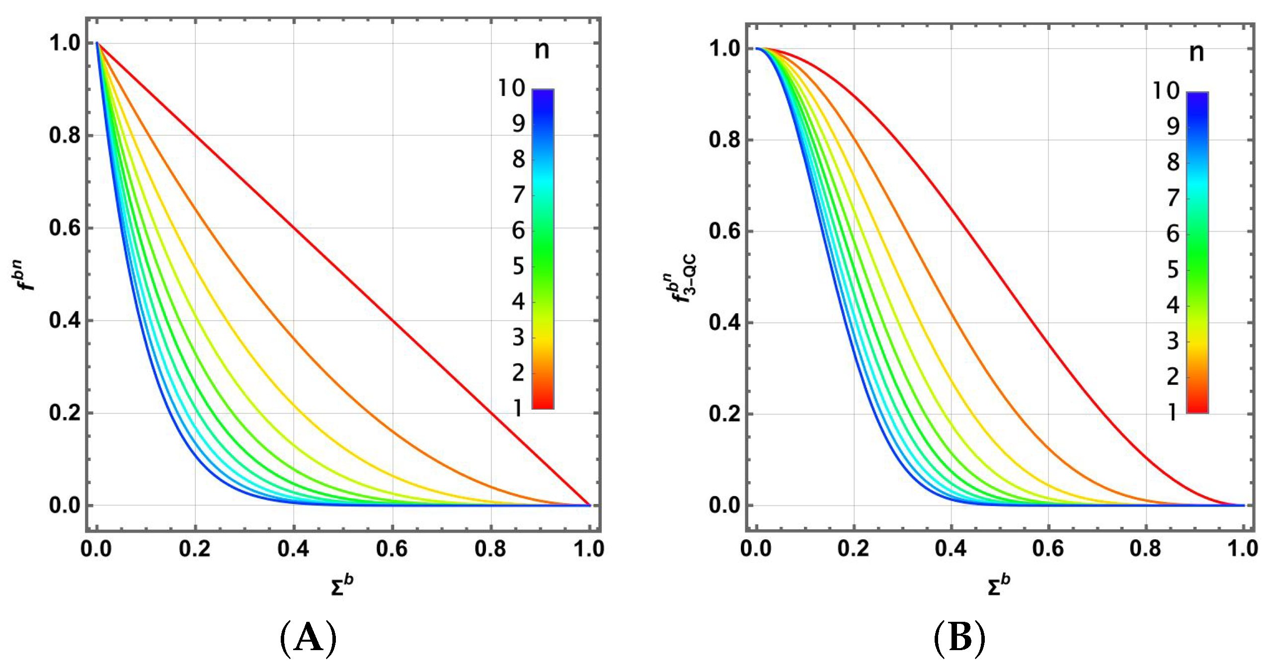
which enhances the transmission performance for Σ b 1 2 . Figure 2 illustrates the behavior of f Ch b n and f 3 - QC b n as functions of the error parameter Σ b and the number n of qubits transmitted [25]. Similarly, a geometric average fidelity can be defined as F ˜ 3 - QC = f 3 - QC 0 · f 3 - QC 1 .

2.3. A Couple of Quantum Architectures with Imperfect Channels

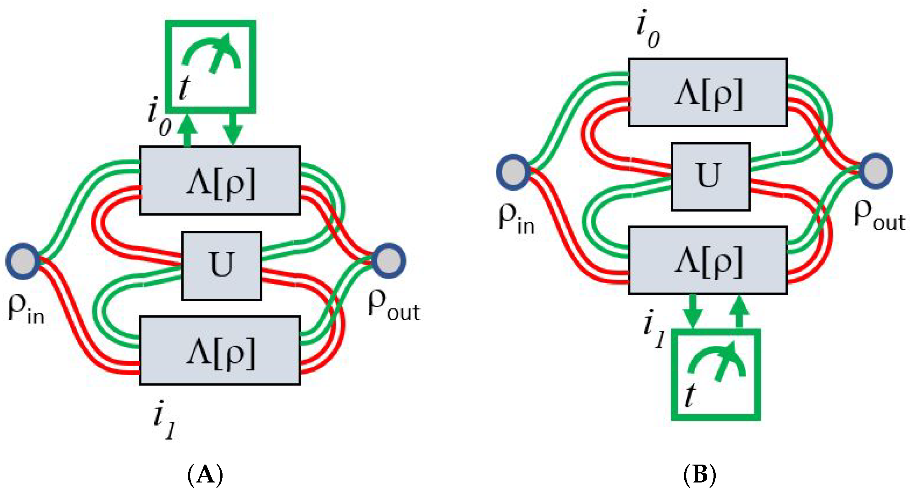
It is well established that imperfections in communication channels can be mitigated when such channels are embedded within transmission schemes capable of generating interference between alternative paths. In these configurations, undesirable effects arising from noise or imperfections can be suppressed through destructive interference, whereas successful transmission is enhanced via constructive interference. Schemes such as Path Superposition (PS) and Indefinite Causal Order (ICO) [24,27] have demonstrated such interference-based improvements. Furthermore, the inclusion of additional intermediate unitary operations enables the tuning or synchronization of desirable interference effects, making them applicable to a wider class of imperfect channels beyond those in which interference naturally arises. Both schemes are illustrated in Figure 3: (A) PS configuration and (B) ICO configuration. PS has long been implemented in photonics and quantum mechanics as a fundamental experimental element, most notably through the Mach–Zehnder interferometer, including extensions to matter systems [28]. In contrast, the ICO originated as a recent theoretical proposal [24], but has already been validated through experimental implementations [29].
It is important to note that each scheme includes a quantum control state | ψ = γ { 0 , 1 } p γ | γ C , with p 0 + p 1 = 1 (not shown), which selects the operational path: green for | 0 C and red for | 1 C .
The corresponding output Λ [ ρ ] for a mixed state ρ can be expressed in terms of their Kraus operators K i 0 i 1 with respect to certain terms i 0 and i 1 in their component channels:
Λ [ ρ ] = i 0 i 1 K i 0 i 1 ρ K i 0 i 1
These Kraus operators can be modeled via form coefficients C α γ , β i 0 i 1 , which depend on the specific components of the underlying Pauli channels [30]. Each coefficient encodes the amplitude associated with a particular transformation from an input basis state | β to an output basis state | α , conditioned on the control state | γ C . More precisely, C α γ , β i 0 i 1 characterizes the transformation applied to the combined input state of the system and control, producing the corresponding output in terms of the state components of the system and control. Therefore,
K i 0 i 1 = α β γ C α γ β i 0 i 1 | α γ C β |

2.4. Composed Pauli Channels Architectures and Kraus Operators

The form coefficients for the PS scheme [30] are the following:
C α γ , β i 0 i 1 = 1 2 p γ α i γ U 1 γ σ i γ 1 γ σ i γ γ U γ α β
These form coefficients comprise the contributions from each possible path, parametrized by the control variable γ , where γ = 0 or 1 correspond to the upper (green) or lower (red) trajectory, respectively. In the PS scheme, only one channel acts per path, and the index 1 γ denotes the complementary path. The form coefficients C α γ , β i 0 i 1 are then constructed using the Kraus operators of the Pauli channels acting along each path, each of the form α i γ σ i γ . The overall coefficient 1 2 ensures that the resulting Kraus operators satisfy the trace-preserving condition (8). Similarly, for the ICO scheme [30]:
C α γ , β i 0 i 1 = p γ α i 0 α i 1 σ i 1 γ U σ i γ α β
where two channels are applied on each path, with the unitary always in the middle. Then, those expressions let us construct the Kraus operators to reach the Λ [ ρ ] expression. By putting all the above expressions together, we obtain the following:
Λ [ ρ ] = i 0 i 1 α β γ α β γ C α γ , β i 0 i 1 | α γ C β | ρ | β α γ C | C α γ , β i 0 i 1
Here, the input state ρ can be chosen as a pure state | ψ ψ | or as a truly mixed state. In the present context, we shall always select the former, as our focus lies in transmitting a sequence of qubits prepared in the state set | 0 , | 1 , | + , | . Moreover, the unitary operation U is represented as U = e i χ n ^ · σ = cos χ σ 0 + i n ^ · σ sin χ , with n ^ = ( sin θ cos ϕ , sin θ sin ϕ , cos θ ) .
As in the previously discussed scenario [25], our interest lies in the non-coherent mixture of output states resulting from each of the aforementioned input states, along with the evaluation of the corresponding fidelity. It is important to note that within this framework there exists an additional quantum system, the control C, which generally becomes entangled with the transmitted state. Consequently, the state of the control system determines the resulting transmitted output state.

2.5. Fidelity and Success Probabilities

In agreement with the previous framework, the fidelity of a process between an input state ρ and an arbitrary pure state ρ may be expressed in terms of the formal coefficients as follows, since ρ is assumed to be a pure state:
f ( Λ [ ρ ] , ρ ) = Tr S Λ [ ρ ] ρ = γ γ ( i 0 i 1 α β α β α | ρ | α β | ρ | β C α γ , β i 0 i 1 C α γ , β i 0 i 1 ) · | γ C γ C |
In fact, the resulting fidelity corresponds to a mixed state of the control system. Consequently, it becomes necessary to select the control state at the end via post-measurement, in order to obtain a specific transmitted state in a stochastic manner. For example, by selecting a measurement basis { | ϕ C 0 = q 0 | 0 + q 1 | 1 , | ϕ C 1 = q 1 | 0 q 0 | 1 with q 0 + q 1 = 1 , the control can be stochastically determined following measurement. Alternatively, one may randomly measure the transmitted state in one of the two bases, as in a quantum key distribution (QKD) protocol, without prior selection of the control state and without certainty regarding the measurement outcome, even if the measurement basis is agreed upon between the sender and receiver. Both approaches will be analyzed in the following sections.

3. Average Fidelities by Tracing the Control System in Quantum Communication

By tracing the control system for the fidelity (13), we obtain its average value in the process without setting a concrete value for such a system:
f T ( Λ [ ρ ] , ρ ) = γ ( i 0 i 1 α β α β α | ρ | α β | ρ | β C α γ , β i 0 i 1 C α γ , β i 0 i 1 )
A direct calculation shows that the four single fidelities for each specific communication Scheme (Sch), Sch = PS and ICO, for the two bases b = 0 , 1 have a similar form:
f Sch b ( Λ [ | j i b j i b | ] , | j i b j i b | ) = A Sch b ( Σ b ) cos 2 χ + ( B Sch b ( Σ b ) + C Sch b ( Σ b ) G Sch b ( θ , ϕ ) ) sin 2 χ
with B Sch b ( Σ b ) , C Sch b ( Σ b ) , G Sch b ( θ , ϕ ) reported in Table 1. This does not depend on the j i b qubit value, neither on p 0 , p 1 , due to the tracing in the control system. In addition, A Sch b ( Σ b ) = B Sch b ( Σ b ) + C Sch b ( Σ b ) . Then, F Sch T = f Sch 0 n 0 f Sch 1 n 1 . If the 3-qubit correction code is additionally applied,
f Sch + 3 QC b = f Sch b ( 3 2 f Sch b )
As before, geometric average fidelities by qubit can be defined for any single or combined scheme as follows:
F ˜ Sch f Sch 0 f Sch 1
for Sch = Ch, 3-QC (single channel plus 3-qubit correction code), PS, PS + 3-QC (path superposition plus 3-qubit correction code), ICO, ICO + 3-QC (indefinite causal order plus 3-qubit correction code). Because A Sch b ( Σ b ) = B Sch b ( Σ b ) + C Sch b ( Σ b ) and due to the form of (15) in terms of χ , we notice that the maximum value for f S c h b is reached if G Sch b ( θ , ϕ ) = 1 . This implies that U is a rotation of the Bloch sphere around the axis defined by | 0 , | 1 for b = 0 and the axis defined by | + , | for b = 1 . Then, χ is arbitrary, to reach the maximum value of f S c h b = A Sch b ( Σ b ) . But only if χ = 0 , U becomes indistinct for both bases b = 0 , 1 , which implies that the best option is the absence of U.

3.1. Path Superposition Scheme

As a result of the previous discussion, for PS, the optimal transmission scheme becomes equivalent to f P S b = 1 Σ b , which is the fidelity for the single channel. Therefore, the absence of interference improves the overall fidelity of the procedure, as illustrated in Figure 3 when U is absent.
An alternate strategy may be considered in this scenario. Instead of a general enhancement for f P S b , it is noticeable that if G PS b ( θ , ϕ ) is the same for both bases b = 0 , 1 (if | cot θ | = | cos ϕ | ), then f P S b = 1 Σ b ( 1 2 Σ b ) ( 1 cos 2 θ ) sin 2 χ . A brief analysis reveals that this value can only be perfectly improved for Σ b = 1 , resulting in f P S b = Σ b ( G PS b ( θ , ϕ ) = 0 , sin 2 χ = 1 for θ = ϕ = χ = π 2 ). This remains a significant outcome, as it was achieved for both bases, providing correction for the noisiest states with Σ b 1 . This simply inverts the plots in Figure 2 around Σ b = 1 2 .

3.2. Indefinite Causal Order Scheme

Instead, for the ICO scheme, the best f I C O b becomes
f ICO b ( Λ [ | j i b j i b | ] , | j i b j i b | ) = Σ b 2 + ( 1 Σ b ) 2 = 1 2 Σ b ( 1 Σ b )
while its 3-qubit correction code version is
f ICO + 3 QC b ( Λ [ | j i b j i b | ] , | j i b j i b | ) = ( 1 2 Σ b ( 1 Σ b ) ) 2 ( 1 + 4 Σ b ( 1 Σ b ) )
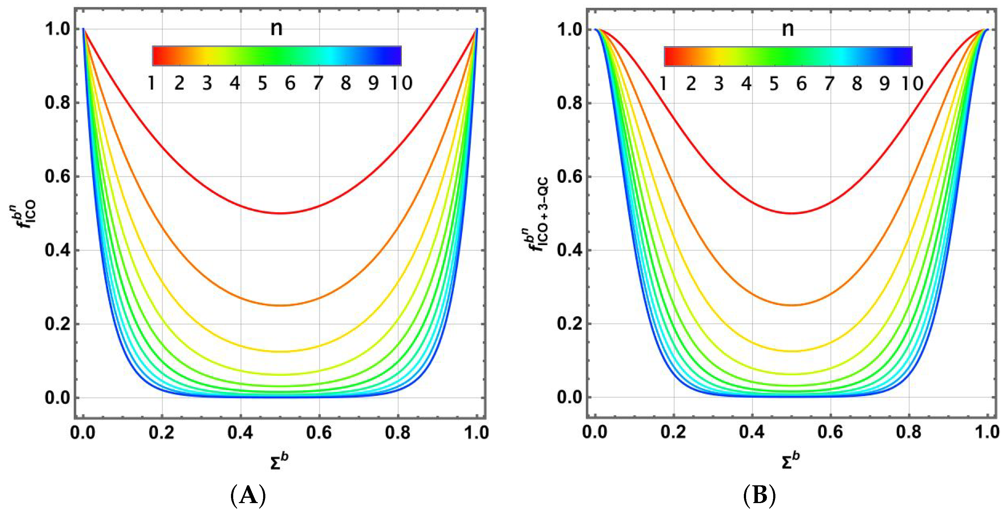
Figure 4 illustrates the behavior of f b ICO n and f b ICO + 3 QC n as a function of Σ b and the number n of transmitted qubits, compared to Figure 2. An improvement in the outcome is observed for Σ b 1 . It is important to note that although the basis for the success of the 3-qubit code relies on a low transmission error, the use of the ICO scheme significantly enhances the noisiest channels, thereby enabling accurate transmission. However, since the transmission should function with the same channel for both bases b = 0 , 1 , the overall effect of this scheme (and the previous ones) should be depicted in the parametric space of the Pauli channels for the corresponding geometric averages.
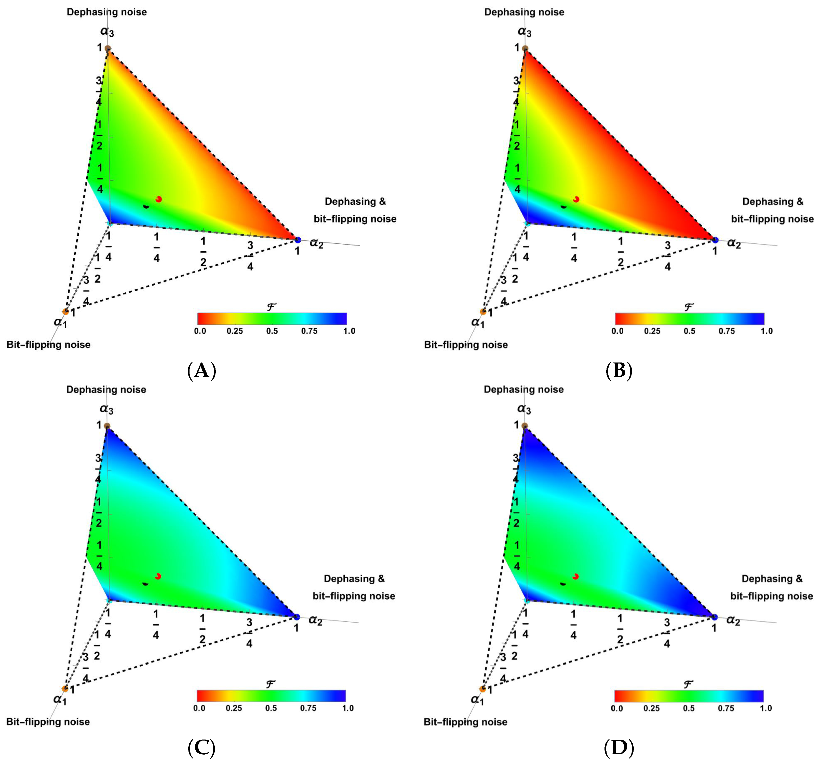
Figure 5 depicts the geometric averages (A) F ˜ Ch , (B) F ˜ 3 QC , (C) F ˜ ICO , and (D) F ˜ ICO + 3 QC in color, represented within the parametric space of the Pauli channels [20,25]. The points in the four corners correspond to (a) the transparent channel ( α 0 = 1 at the origin) and the primary pure syndromes, (b) the bit-flipping channel ( α 1 = 1 ), (c) the dephasing channel ( α 3 = 1 ), and (d) the bit-flipping combined with the dephasing channel ( α 2 = 1 ). Additionally, the black dot corresponds to the depolarizing channel ( α 0 = α 1 = α 2 = α 3 = 1 / 4 ), while the red dot represents the ICO-channel ( α 1 = α 2 = α 3 = 1 / 3 ) [20]. Only one-half of the complete plot is shown in each case due to the expected symmetry of the geometric averages ( f Sch 0 exchanges with f Sch 1 by switching α 1 and α 3 ). An increasing improvement in the geometric fidelity generated by the ICO scheme is observed. Table 2 reports the mean μ Sch and the standard deviation σ Sch for the geometric mean fidelity of these transmission schemes across the entire parametric space of the channels. However, the 3-QC scheme enhances the fidelity in the vicinity of the transparent channel and for many others deteriorates it. This effect varies with other schemes.

4. Average Fidelities with Measuring the Control System in Quantum Communication

By initially measuring the control system to stochastically determine its state for the measurement basis | ϕ C 0 , | ϕ C 1 previously defined, we assume that the fidelity improves in the privileged state | ϕ C 0 . Consequently,
f M ( Λ [ ρ ] , ρ ) = 1 P 0 γ γ q γ q γ ( i 0 i 1 α β α β α | ρ | α β | ρ | β C α γ , β i 0 i 1 C α γ , β i 0 i 1 )
But such a state only has a certain probability P 0 to arise. This should be obtained as follows:
P 0 = Tr S Tr C ( Λ [ ρ ] | ϕ C 0 ϕ C 0 | ) = i 0 i 1 α β γ β γ q γ q γ C α γ , β i 0 i 1 β | ρ | β C α γ , β i 0 i 1

4.1. Path Superposition Scheme

Under this stochastic procedure, we first analyze the PS architecture. As noted previously, any communication distribution should preferably be independent of the basis and the state being transferred. This implies that (a) f Sch b ( Λ [ | j i b j i b | ] , | j i b j i b | ) = f Sch b ( Λ [ | j i b j i b | ] , | j b i j b i | ) for j j and arbitrary b; and (b) f b Sch ( Λ [ | j i b j i b | ] , | j i b j i b | ) = f b Sch ( Λ [ | j i b j i b | ] , | j i b j i b | ) for b b and arbitrary i.
In this scenario, Sch = PS, the expressions for f PS b ( Λ [ | j i b j i b | ] , | j i b j i b | ) , b = 0 , 1 , i = 0 , 1 derived from (20) are extensive and complex, making it impractical to include the complete final expressions here. These expressions depend on the parameters p 0 , q 0 , χ , θ , ϕ and have a structure similar to (15), but with more complex A Sch b , B Sch b , C Sch b values compared to those of Table 1, no longer dependent on Σ b but still involving the α i parameters of each channel. However, we found that none of the previous prescriptions were satisfied, resulting in variations for each transmitted state and basis used, rendering the scheme impractical.

4.2. Indefinite Causal Order Scheme

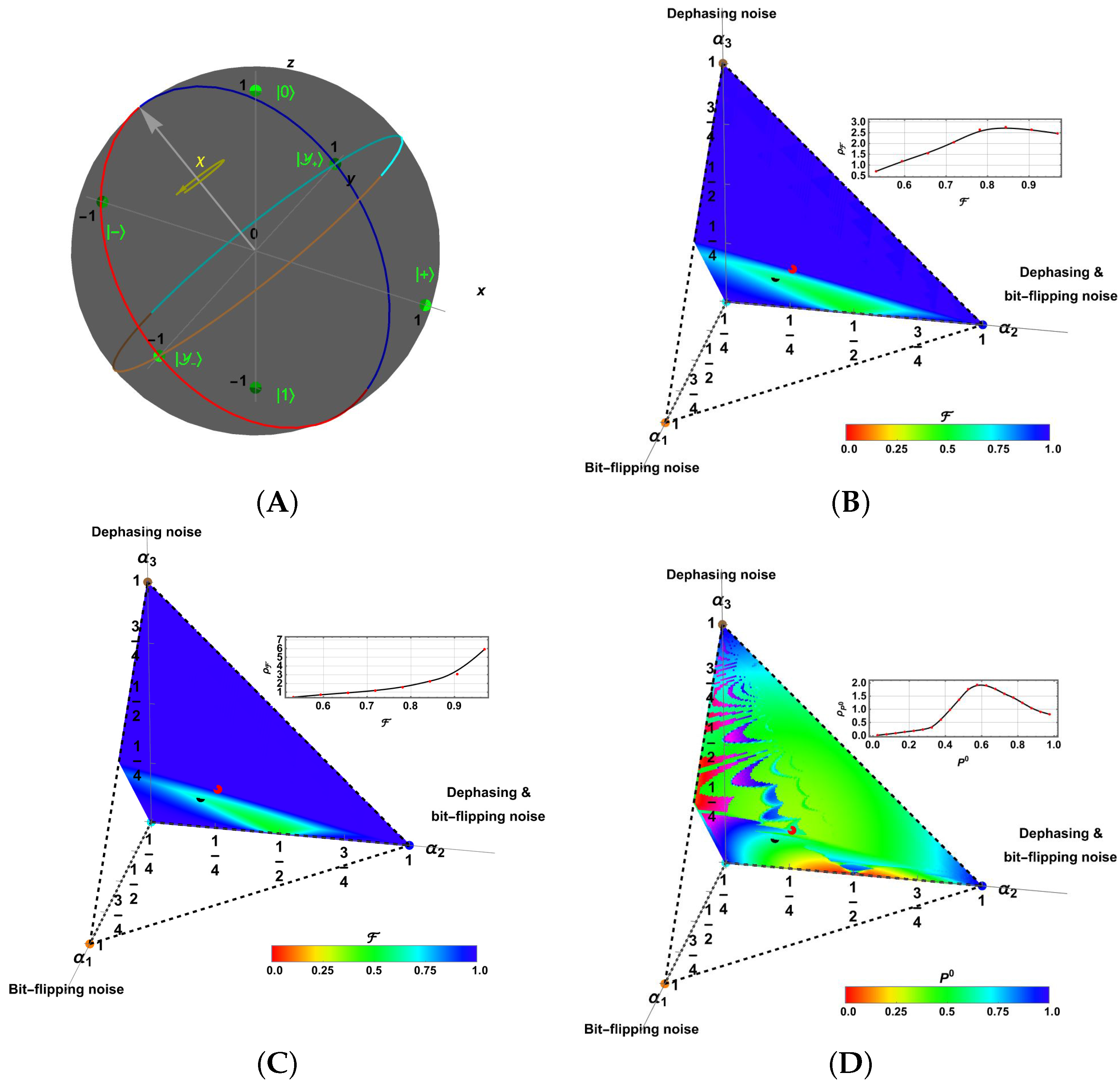
Following the prescriptions stated for f ICO b ( Λ [ | j i b j i b | ] , | j i b j i b | ) in the previous subsection, we choose a control state to obtain | ϕ C 0 with probability P 0 . A direct calculation allows us to derive the general expressions. These expressions are, as before, too large and complex to be reported here but possess an additional natural property; they fulfill the first condition: f ICO b ( Λ [ | j i b j i b | ] , | j i b j i b | ) = f ICO b ( Λ [ | j i b j i b | ] , | j i b j i b | ) for j j and b, taking arbitrary values. An additional restriction is required to fulfill the second condition: | cot θ | = | cos ϕ | . This is the same necessary condition for the PS scheme in the tracing procedure described in Section 3.1. This restricts local unitary operations U to rotations around directions in certain maximal circles, as shown in Figure 6A (maximal circles in red, blue, cyan, and brown colors). Hence, rotations by an angle χ should be restricted around any direction lying on the maximal circles (grey arrow).
With the expressions for f ICO b ( Λ [ | j i b j i b | ] , | j i b j i b | ) , b = 0 , 1 (basis) and i = 0 , 1 , we have numerically solved the optimization problem for the geometric mean fidelity F ˜ ICO = f ICO 0 f ICO 1 at each point in the parametric space of the Pauli channels ( α 1 , α 2 , α 3 ) , with α i [ 0 , 1 ] , i = 0 , . . . , 3 , fulfilling i = 0 3 α i = 1 . This optimization involves finding a set of values p 0 , q 0 , χ , θ ( ϕ depending on θ ) to maximize F ˜ ICO . In this analysis, p 0 was set to 1 2 for simplicity (noting that the previous properties of f ICO b do not depend on this choice). The optimal values are colored in Figure 6B, with the bluest indicating the highest F ˜ ICO and the reddest indicating the lowest. These results are significantly better than those shown in Figure 5 for other channel arrangements. The results are above F ˜ ICO = 0.5 . The upper inset shows the distribution of values F ˜ ICO with μ F ˜ ICO = 0.725 and σ F ˜ ICO = 0.125 throughout the parametric space (see Table 2 for comparison).
Moreover, we can now improve the previous result by implementing the 3-qubit correction code. In such a case,
f ICO + 3 QC b = f ICO b ( 3 2 f ICO b )
Thus, as before, optimizing the function F ˜ ICO + 3 QC = f ICO + 3 QC 0 f ICO + 3 QC 1 at each point in the Pauli channel parametric space for the appropriate values of q 0 , χ , θ , ϕ (as before, ϕ depends on θ , and p 0 was initially fixed at 1 2 ), the optimal results are shown in Figure 6C in color, similarly to F ˜ ICO . A slight improvement was observed for several channels. The upper inset shows the distribution of values F ˜ ICO + 3 QC in the parametric space with μ F ˜ ICO + 3 QC = 0.861 and σ F ˜ ICO + 3 QC = 0.127 (see Table 2 for comparison).
It should be clear that the improvement compared to the tracing scheme was because measuring introduced a filter on the average procedure (represented by the tracing). However, because these latter schemes are stochastic, an additional analysis should be performed for the values of P 0 . These values determine their feasibility. Since ICO + 3-QC is an improved error correction code of ICO, both are optimally achieved under the same parameters q 0 , χ , θ . Thus, the P 0 values for the optimal F ˜ ICO , F ˜ ICO + 3 QC have a statistical distribution throughout the parametric space of the Pauli channel, with μ P 0 = 0.682 and σ P 0 = 0.219 . These values are represented in color in this parametric space in Figure 6D, and the upper inset shows the statistical distribution. The P 0 values are high enough to produce an improved communication procedure using the ICO architecture, as shown by the mean μ P 0 and the inset with a distribution peak around P 0 0.6 . Despite this, note that ICO + 3 QC exhibits a lower success probability than P 0 3 = 0.317 . Despite its fidelity, it requires repeating the procedure several times before a measurement success. This makes this procedure only selective for certain channels with higher P 0 3 (blue zones in Figure 6D). Nevertheless, in such a P 0 -map with high variability, the zones with P 0 1 include the channels near to the different pure syndromes α i 1 , i = 0 , . . . , 3 where also F ˜ 1 . In particular, the channels near the pure syndromes exhibit not only a higher geometric average for fidelity but also a higher success probability. We analyze these particular but relevant cases in the next subsection.

4.3. Improved Fidelity with ICO Architecture for Emblematic Channels

Despite being stochastic, the ICO architecture demonstrated superior performance in improving the average fidelity when qubits were encoded in the two analyzed bases. For this reason, we considered certain emblematic channels that are commonly considered meaningful. In syndromic channels, such as bit-flipping noise ( α 1 ), dephasing noise ( α 3 ), or their combination ( α 2 ), mixed with the transparent channel ( α 0 ), the ICO architecture exhibited a notable response that enhanced the fidelity F ˜ ICO , as illustrated in Figure 6B. In a further development, we omitted the additional 3-qubit correction code, to analyze the complete family of channels, without the restrictions imposed by this correction procedure.
Although not reported here, our analysis of the numeric solutions obtained for Figure 6B revealed that they fell at the extreme points in the curves of Figure 6A ( θ = π 2 , then ϕ = π 2 , 3 π 2 , which implies rotations around the y axis), with χ = 0 , π providing the best fidelity.
With these selections ( p 0 = p 1 = 1 2 , | cot θ | = | cos ϕ | , θ = π 2 , and χ = 0 , π ), the four expressions ( b = 0 , 1 and i = 0 , 1 ) for f ICO b ( Λ [ | j i b j i b | ] , | j i b j i b | ) in (20) have the same form (by exchanging α 1 and α 3 between cases with b = 0 and b = 1 ):
f ICO b ( Λ [ | j i b j i b | ] , | j i b j i b | ) = 1 P 0 ( q 0 q 1 + 1 2 ) h ( α 1 + 2 b , α 2 ) + 2 α 1 + 2 b α 2 with : h ( α , β ) = 1 2 α ( 1 α ) 2 β ( 1 β ) = 1 2 ( α + β ) ( 1 ( α + β ) ) 4 α β
with P 0 obtained directly from (21) when the same restrictions are imposed. Thus, F ˜ ICO and P 0 adopt shorter forms:
F ˜ ICO = 1 P 0 ( q 0 q 1 + 1 2 ) h ( α 1 , α 2 ) + 2 α 1 α 2 1 2 ( q 0 q 1 + 1 2 ) h ( α 2 , α 3 ) + 2 α 2 α 3 1 2
P 0 = 1 2 + q 0 q 1 1 4 i , j = 1 i < j 3 α i α j
Note that h ( α , β ) almost fits the expression (18). The term 2 α i α j in the previous expression becomes a loss for F ˜ ICO M over F ˜ ICO T as a function of q 0 = 1 2 and α i , where i = 1 , 2 , 3 . This term originates from the measurement strategy, but is mitigated by the presence of P 0 1 in the denominator of F ˜ ICO in (24).
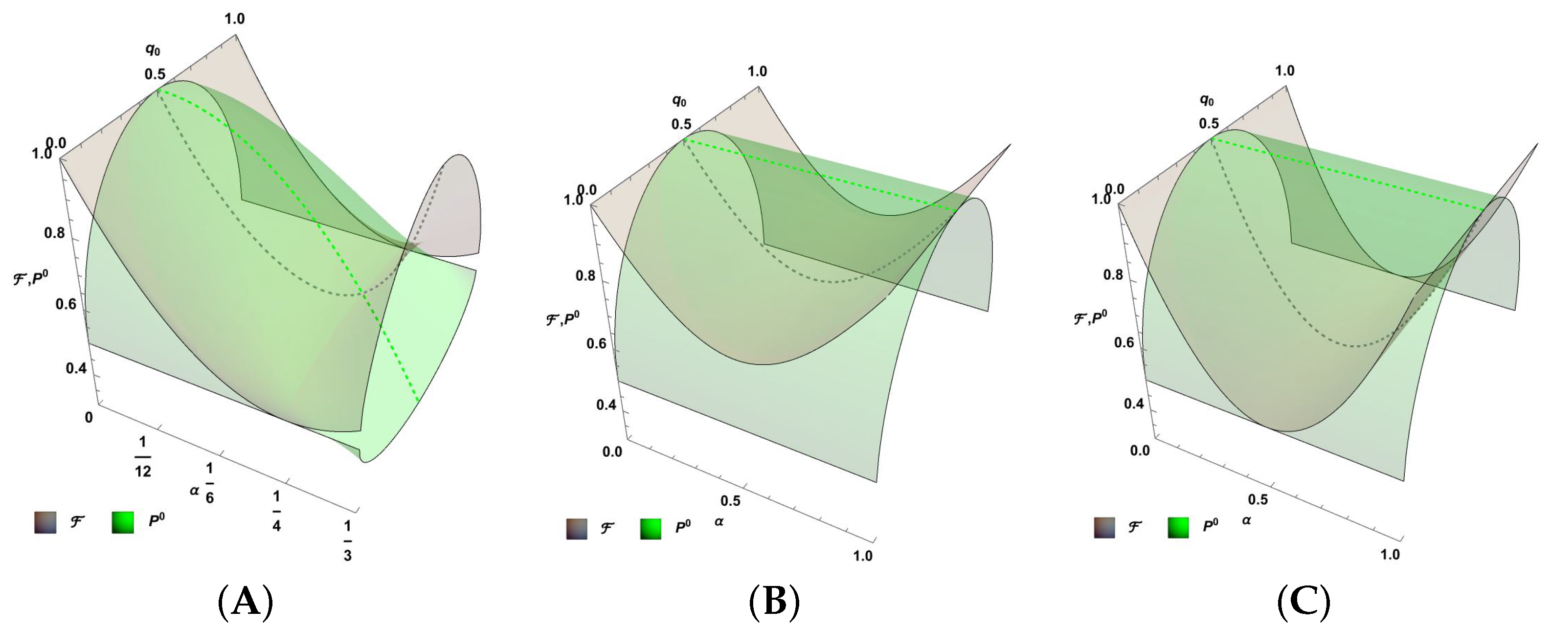
There are two distinct situations for the syndromic cases mixed with the transparent channel. Because the syndrome for α 2 affects the states in both bases considered, the scenarios α 1 = α 3 = 0 , α 2 = α [ 0 , 1 ] exhibit a different behavior compared to those with α 2 = α j = 0 , α i = α [ 0 , 1 ] , where i = 1 , j = 3 or i = 3 , j = 1 . In addition to these distinct scenarios, we consider a third case: the central line of the parametric space, α i = α [ 0 , 1 3 ] , for i = 1 , 2 , 3 , which first ranges from the transparent channel towards the depolarizing channel, and then to the ICO channel. These three scenarios are depicted in Figure 7, showing F ICO (grey surface) as a function of the parameters q 0 and α defined above for each scenario. Similarly, the green surface represents P 0 . In all three scenarios, the special solution for q 0 = 1 2 is highlighted for F ˜ ICO and P 0 , as it provides the optimal solution for the average fidelity.
The central line is first analyzed in Figure 7A. There is a decrease in fidelity near the depolarizing channel α = 1 4 , specifically at α = 3 3 6 . However, the stochastic process for channels near α = 1 3 , despite the high fidelity, has a low probability of success of P 0 = 1 3 . In Figure 7B, the case where only α 1 0 or α 3 0 (apart from α 0 ) is considered. In fact, for q 0 = 1 2 , P 0 = 1 and the fidelity improves greatly near the channel with α = 1 ( α 1 or α 3 ). In this scenario, we have F ˜ ICO 1 2 (equality occurs in q 0 = 1 2 , α = 1 2 ). Finally, the case with α 2 0 (apart from α 0 ) shows a similar behavior, but with a greater decrease near α = 1 2 as expected. However, the extreme α 2 = 1 also achieved the highest fidelity. In this scenario, F ˜ ICO 1 2 (the equality occurs in q 0 = 1 2 , α = 1 2 ). Clearly, in the last three families of channels, either because only one of α 1 , α 2 , α 3 is different from zero, or because all are equal, the performance for F ˜ ICO is equivalent to the tracing scheme if q 0 = 1 2 . Additionally, note that the 3-qubit code still enhances the last cases for fidelities close to one.

5. Eavesdropping Under the Communication Schemes for QKD

5.1. Single Eavesdropping Attack Through Measurement and Replacement

In this section, we shall analyze the modified effectiveness of an eavesdropper attempting to intercept the information being transmitted through a channel. For this analysis, we will consider the optimal scheme established in our previous work, specifically the ICO channel under the stochastic approach. To approximate the impact of eavesdropping, we simplify the action by considering a single man-in-the-middle attack [31]. Here, the eavesdropper performs a measurement and subsequently replaces the intercepted qubit. However, within this scheme, the eavesdropper can only access one of the single communication channels, specifically the channel with p 0 strength in our procedure, for example. Assume that the transmission for each channel in the ICO architecture depicted in Figure 3 occurs over a unitary time T = 1 , thus the attack is executed at time t < T . At this point, the qubit does not completely cross the channel, so if the effect on the information is linearly accumulative, the portion of the channel already crossed possesses the α i parameters [25]:
A j ( t ) = ( 1 t ) + α 0 t , j = 0 α j t , j = 1 , , 3
in terms of the original parameters and t when the entire channel is crossed. Thus, if the control state is | 0 C , the qubit enters a portion of the channel, is intercepted, and measured in one of the possible bases | 0 , | 1 ( b = 0 ) or | + , | ( b = 1 ). This occurs as a guess of the eavesdropper, with a probability of 1 2 of matching the same transmission basis used by the transmitter (see Figure 8A). Here, M b , κ represents the measurement operators for the bases b = 0 , 1 , respectively, as before, and κ = 0 , 1 for each of the preceding states in those bases. Consequently, the eavesdropper measures and replaces the qubit, which then proceeds to the remaining part of the channel characterized by the parameters A j ( 1 t ) . The subsequent path follows the same pattern as previously within the ICO architecture. The path followed when the control state is | 1 C remains unchanged. Thus, by defining,
B j γ ( t ) = A j ( t ) , γ = 1 T j , γ = 0
In this expression, T k represents the set of α j parameters for the transparent channel, where α 0 = 1 . The form coefficients of this process can be expressed as
C α γ , β i 0 i 1 j 0 j 1 b κ = 1 2 1 + γ 2 p γ α i 1 γ B j γ 1 γ ( 1 t ) A i γ ( t 1 γ ) σ i 1 γ U σ j γ M b , κ 1 γ σ i γ α β
The different elements of this expression can be compared with those of (11). All superscripts are powers 0 or 1, showing if each operator is applied or if t = 1 . The coefficient 1 2 should be introduced for normalization due to the introduction of j 0 , j 1 , while the coefficient 1 2 γ is due to the sum in κ = 0 , 1 for γ = 1 , where there is no measurement. Thus, the Kraus operators and Λ [ ρ ] become
K i 0 i 1 j 0 j 1 b κ = α β γ C α γ , β i 0 i 1 j 0 j 1 b κ | α γ C β |
Λ b [ ρ κ b ] = i 0 i 1 j 0 j 1 b κ K i 0 i 1 j 0 j 1 b κ ρ κ b K i 0 i 1 j 0 j 1 b κ
However, in the present scenario, we are specifically interested in the case where b = b . When the eavesdropper attack is executed in the second channel of the ICO architecture (still with the control state | 0 C , see Figure 8B) within the time interval T < t < 2 T , the form coefficients are alternatively expressed as
C α γ , β i 0 i 1 j 0 j 1 b k = 1 2 1 + γ 2 p γ B j 1 γ 1 γ ( 2 t ) A i 1 γ ( ( t 1 ) 1 γ ) α i γ σ j 1 γ M b , κ 1 γ σ i 1 γ U σ i γ α β

5.2. Analysis of the Eavesdropper Success Probability

In this section, we analyze the eavesdropper’s probability of success. This refers to the scenario where the eavesdropper successfully guesses the used basis (with a probability of 1 2 ) and successfully deceives the communication processes, remaining undetected during reconciliation, while also stealing the correct qubit state that is transmitted and received during the process [32]:
P success t , b , κ = 1 2 Tr ( ρ κ b Λ b ( ρ κ b ) )
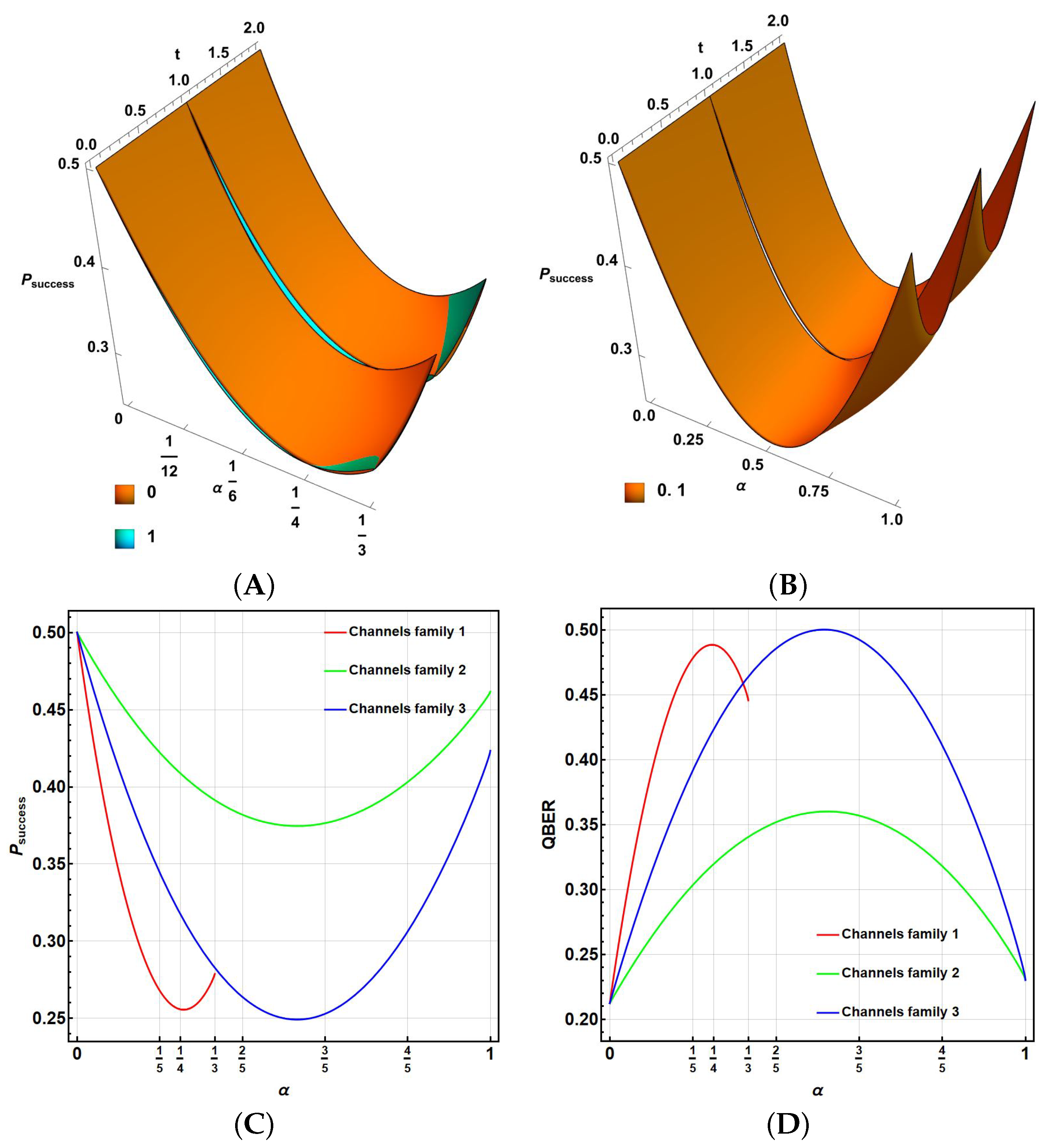
for Λ b [ ρ κ b ] in (29), considering that the input state is pure and ρ κ b = | κ b κ b | , with κ = 0 , 1 corresponding to 0 , 1 if b = 0 and + , if b = 1 . This means ρ κ b { | 0 0 | , | 1 1 | , | + + | , | | } . Note that P success depends on the basis b = 0 , 1 ( | 0 , | 1 and | + , | , respectively) and the state encoded as k = 0 , 1 ( | 0 , | + and | 1 , | , respectively) on the correspondent basis. The factor 1 2 is due to the guessing of the basis. All restrictions and values for the parameters θ , ϕ , χ , p 0 , q 0 will be the same as those used in Section 4.3 for the analysis of emblematic states. Nevertheless, those expressions are too large to be included here, but can be compared and plotted. Interestingly, they finally only depend on the encoded state 0 for | 0 , | + and 1 for | 1 , | . Figure 9 presents the results for P success for the three families of channels considered in Section 4.3.
Thus, Figure 9A shows the value of P success as a function of α [ 0 , 1 3 ] and t [ 0 , 2 ] (the attack time during the communication process) for the family of channels located along the central line of the parametric space of the Pauli channels ( α j = α for j = 1 , 2 , 3 ). The outcome is consistent across the two bases. For the 1 encoding (cyan), it is slightly below that of 0 (orange). Note that there is a discontinuity at t = 1 due to the effect of U. For the transparent channel, where α = 0 , the maximum value is P success = 1 2 . For higher values of α , P success decreases to nearly 1 4 . Both plots for 0 (orange) and 1 (cyan) fit almost perfectly (the green region represents the most accurate fit). The value P success = 1 4 was achieved for both cases in a depolarizing channel ( α = 1 4 ).
The second family includes all channels with α 2 = 0 , either α 1 or α 3 equal to α . In this case, Figure 9B shows P success for the basis | 0 , | 1 . The plot for the basis | + , | is not shown because it is trivial with P success = 1 2 . This latter case is noteworthy because it is independent of t and α , achieving the highest possible value, similarly to traditional QKD processes (such as the BB84 protocol [33]). For this family, in addition to the expected result for the transparent channel, for the basis | 0 , | 1 , we observed a dependence on t. The intermediate times in each part of the process ( t 1 2 , 3 2 ) do not always favor the eavesdropper (more noticeable for α 1 ). For the basis | + , | , the measurement process always provided the correct state if the eavesdropper correctly identified the transmission basis. In this case, no discontinuity was observed at t = 1 .
Finally, for the third family with α 2 = α and α j 2 = 0 , Figure 9B provides the values of P success for the two bases. No discontinuity was observed at t = 1 for this family. Taking into account the randomness in the selection of bases and codification (0 or 1), we can determine an average success probability as a function of α for each family [25], integrating over t and averaging over the bases ( b 0 , 1 ) and state codification (0 for | 0 , | + and 1 for | 1 , | ):
P ¯ success = 1 8 b { 0 , 1 } k { 0 , 1 } n = 0 1 n n + 1 P success t [ n , n + 1 ] , b , k d t
Figure 9C summarizes the findings, displaying P ¯ success for the three previous channel families in red, green, and blue, respectively. Note the non-trivial dependency of P ¯ success on α , with P ¯ success 1 2 in all three cases, demonstrating that the communication scheme does not favor the eavesdropper, even in cases with significantly improved fidelity (close to α = 1 3 for the first family or near α = 1 in the last two cases). As expected, the outcome for the second family was higher than that for the third, due to the partial corresponding outcome for the basis | + , | . Note, in particular, the asymmetric gaps between α 0 and α 1 3 , 1 despite the significantly improved fidelity at both extremes.

5.3. Analysis of Quantum Bit Error Rate

The Quantum Bit Error Rate (QBER) [34] represents the total probability of detecting the eavesdropper during the coincidental basis reconciliation process conducted between the sender and the receiver. This involves detecting the opposite result ρ κ b ρ b κ 1 from the original transmitted state ρ κ b , as well as utilizing the basis b 1 as the measurement basis of the eavesdropper during qubit interception. Therefore, considering Λ b 1 [ ρ κ b ] in (29):
P QBER t , b , k = Tr ( ρ κ b Λ b 1 [ ρ κ b ] )
QBER = 1 8 b { 0 , 1 } k { 0 , 1 } n = 0 1 n n + 1 P QBER t [ n , n + 1 ] , b , k d t
Figure 9D illustrates the QBER results for the three previously mentioned channel families, represented in red, green, and blue, respectively. Although the typical result for a traditional QKD process (such as the BB84 protocol [33]) is QBER = 1 4 , here the communication process generally increased the value of QBER, with potential exceptions for channels that act as transparent channels ( α 0 , 1 ), due to the communication strategy. As anticipated, these outcomes exhibited nearly the opposite behavior to the previous P ¯ success , with minor differences due to the use of the ICO scheme.
Thus, while for the original near-transparent channels, faithful transmission was enhanced, and the eavesdropper’s success probability and QBER nearly retained their traditional values, this was not entirely true for the noisiest channels. Despite achieving transmission rate recovery, the success rate of the eavesdropper remained reduced compared to traditional direct values (such as those of the BB84 protocol). Consequently, this procedure not only enhanced the communication fidelity, but also further diminished the likelihood of successful eavesdropping.

6. Discussion and Future Work

Several aspects of the current work should be discussed in terms of limitations and applicability extensions, particularly those related to more general communication channels; feasible complementary techniques to enhance the architecture outcomes beyond the 3-qubit code contribution; and, alternatively, more advanced eavesdropping attacks.

6.1. Extension to More General Channels

Although the development was centered on Pauli channels, note that the procedure could similarly be followed for any linear channel with arbitrary Kraus operators Λ [ ρ ] = i = 0 3 K i ρ K i . Moreover, because linearity is an important aspect of the analysis, the treatment for non-linear and non-Markovian quantum channels is not direct, but rather iterative, at least for some types of channels [35]. Thus, for linear channels, because K i = α i V i in the Kraus representation, with V i being a group of unitary operations [22], we can still exploit the algebra properties of Pauli matrices in expressions (10) and (11) by expressing V i = j = 0 3 κ j i σ j . Furthermore, other channel representations, such as the Stinespring and Choi representations, are equivalent to the Kraus representation [36]; thus, channels such as amplitude damping, reset, complete dephasing, and projective measurement are included. Of particular interest is applying the procedure to certain linear correlated multi-channel models. This is a future work task, and it is expected that unitary control operations U will become diversified. In this task, it is expected that U will depend on the κ j i parameters. Although the estimation of quantum parameters is an optimization task limited by the quantum nature of the channel, for the ICO architecture, it has been shown to improve the estimation [37]. Furthermore, the use of machine learning algorithms could become valuable in this area [38,39].

6.2. Feasibility of Complementary Methods for Error Correction to the Current Architectures

These methods, complemented with simple error correction techniques, such as the 3-qubit code, have made it possible to improve transmission procedures, operating indistinctly on a pair of coding bases that serve as a secrecy strategy in QKD processes. Note that improved traditional QEC procedures, such as surface codes [40] or concatenated codes [41], could also be implemented to increase robustness. However, these methods have a large overhead space, meaning that they require a large number of physical qubits per logical qubit. In our procedure, the quantum nature of errors works genuinely passively, without requiring a large number of physical qubits to set a logical qubit, to boost the information improvement already gained with the primary procedure. Instead, Low-Density Parity Check (LDPC) codes [42] or their closely related turbo codes are slender codes that also use redundancy but show adaptability to the capacities of certain channels, making them better complementary candidates to the considered architectures, especially for fixed code rates and increasing block lengths.

6.3. Expectations for Multiple or Coherent Eavesdropping

These redundancy methods improve the reduction introduced by quantum communication architectures (PS and ICO), which have significantly reduced the eavesdropping success rate as a function of the original transparency loss of the channel. Thus, while the improvement in fidelity is remarkable, it also reduces the success and detection of the eavesdropper. In fact, since these processes have precise prescriptions, their alteration usually introduces errors that do not facilitate eavesdropping. As was insightfully analyzed for the best process, based on ICO, the architecture notably reduces the ability of an eavesdropper to succeed in a QKD process, making them more vulnerable within a typical reconciliation process between the sender and the receiver.
Eavesdropping based on multiple attacks could present a different scenario. The use of redundant additional methods suggests several possibilities for multiple eavesdroppers to work together [43], for instance: (a) multiple points of information procurement to perform network sniffing and active eavesdropping, (b) capturing and retransmitting valid data to perform information reconstruction and disruption cleaning actions, and (c) performing several symmetrical attacks on the two paths of ICO, where the eavesdroppers could use a device-dependent attack to exploit the same destructive interference properties of the architecture to conceal their presence, particularly if they can manipulate the control U (or replace it with another more convenient for their purposes). However, there are obstacles to these actions: (1) stochastic results (such as measurement) could limit or hamper an eavesdroppers’ actions, (2) the sender–receiver parties could modify the intermediate control U to detect the presence of eavesdropping, and (3) the previous implementation of undefined encryption using a shared communication process [44].
In another trend, if a coherent attack is performed, the eavesdropper will attempt to interact with more than one qubit at a time. In the BB84 approach, this strategy generally does not provide more information to the eavesdropper; instead, it improves the probability of guessing the entire key or part of it [45]. Nevertheless, such a strategy for the ICO approach would require precise control over the transiting times for the qubits through the channel (even without a redundant complementary procedure; the easiest way). All of these possibilities should be investigated with priority in future work.

6.4. Integration of PS and ICO in Current Commercial QKD Systems in the NISQ Era

Although PS in photonics has been commonly achieved in quantum commercial applications such as photonic chips, the challenge is the control of the optical length of paths and the individual discrimination of photons, as well as the fine control required over time in the laser pump. The ICO architecture inherits this latter aspect, despite the more elaborate setup, higher calibration, and practical complexity required [29,46]. Two greater challenges include (a) scalability to reach larger distances and higher key generation rates, and (b) integration with existing commercial QKD technologies, which still imply high costs for QKD systems. This latter complexity becomes critical when sharing information with NISQ devices, which are prone to noise and errors, compromising the reliability and security of QKD processes. In these terms, these techniques require precise theoretical descriptions and analysis, together with hard simulations as scalability increases, because each causal relation should be tracked.
In our approach, with only two paths (in PS and ICO), these possibilities increase the combinatorial terms in the expressions, thus exponentially leading to computational complexity and impacting the feasibility of the theoretical analysis [27]. However, as demonstrated here, the introduction of methods such as form coefficients eases the theoretical approach [37,47]. In any case, there is an increase in complexity with the number of systems and the scalability of the connectivity network. To manage an increase in the number of systems, some other hybrid approaches will become necessary, such as the use of variational approaches such as tensor network techniques or random sampling approaches, such as Monte Carlo methods.

6.5. Further Applicability for Information Enhancement and Future Work

This work has discussed the ability of setups such as PS and ICO in the transmission of qubit chains to correct the impact of imperfect channels, whether they are large communication channels or necessary and localized components in a processing or communication procedure. Although the application under consideration was analyzed under the generic QKD scheme to consider a secrecy process and additionally eavesdropping under a simple individual attack scheme, other applications can be found, not only in the fields of quantum cryptography, but also in quantum-secret-sharing schemes for multiple parties [44,48], image transmission [49], imperfect teleportation [50], or simply in the phase drift problems observed in free-space communications [51], thus extending the scope of the findings. Therefore, the architectures presented exploit the imperfect nature of communication channels to selectively eliminate noise or decoherence, functioning as passive elements complemented with intermediate correction strategies (either simple operations such as the unitary ones introduced here or those using intelligent methodologies such as quantum machine learning) or classical protocols (such as the single 3-qubit correction code discussed), establishing adaptive complementary procedures for different configurations and applications.

7. Conclusions

Deviations in communication processes involving quantum states involve a combination of the underlying noise and imperfections introduced by the channels or materials of transmission. Even if control technologies can, in the future, reduce the noise level, this task may be much more complex and expensive due to the design of ideal materials. Thus, QEC and QEM techniques are a topic of permanent development in these applications.
Although there are a variety of methods to reduce these incoherent imperfections in the communication process, methods that exploit quantum properties are often solutions in themselves. In this work, PS and ICO, combined with complementary control elements such as selective unit operations, allowed the performance analysis of these redundant QEM schemes. However, if it is more effective for certain subsets of channels, the implementation of Pauli twirling [16] could extend this effectiveness to other arbitrary channels. In addition, compatible and complementary QEC methods are able to boost the improvement in information, particularly when combined with more advanced non-passive methods. Several aspects of those dominions should be taken into account as regards the current development.
In this work, the entire family of Pauli channels was analyzed under QEC architectures based on PS and ICO, greatly improving their performance. In future work, extended model channels should consider general linear channels and correlated multichannels. Complementarily, simple error correction methods were analyzed in a complementary way, which can be replaced by other more efficient methods, such as LDPC codes, which are expected to generate even better results. In addition, simple attack techniques were analyzed to test the central QEM procedures presented. However, like many other improved QKD procedures, the current scheme should be analyzed under multiple, weakness-based, and coherent attacks [52]. Therefore, other eavesdropping procedures should be studied in future work, along with QEC techniques, in addition to the QEM techniques introduced and analyzed here.

Funding

This research received no external funding.

Data Availability Statement

Data is contained within the article.

Acknowledgments

The author acknowledges the School of Engineering and Science of the Tecnologico de Monterrey for support in publishing this article. The author also acknowledges the support of SECIHTI.

Conflicts of Interest

The author declare no conflicts of interest.

Abbreviations

The following abbreviations are used in this manuscript:
ChSingle channel
ICOIndefinite Causal Order
ICOIndefinite Causal Order plus 3-qubit correction code
LDPCLow-Density Parity Check
MMeasuring
NISQNoise Intermediate-Scale Quantum
PSPath Superposition
PS + 3-QCPath Superposition plus 3-qubit correction code
QBERQuantum Bit Error Rate
QCQuantum Commuication
QECQuantum Error Correction
QEMQuantum Error Mitigation
QKDQuantum Key Distribution
SchScheme
TTracing

References

  1. Rozenman, G.; Kundu, N.K.; Liu, R.; Zhang, L.; Maslennikov, A.; Reches, Y.; Youm, H. The quantum internet: A synergy of quantum information technologies and 6G networks. IET Quantum Commun. 2023, 4, 147–166. [Google Scholar] [CrossRef]
  2. Khan, M.; Ghafoor, S.; Zaidi, S.; Khan, H.; Ahmad, A. From quantum communication fundamentals to decoherence mitigation strategies: Addressing global quantum network challenges and projected applications. Heliyon 2024, 10, 2405–8440. [Google Scholar] [CrossRef]
  3. Illiano, J.; Caleffi, M.; Manzalini, A.; Cacciapuoti, A.S. Quantum Internet Protocol Stack: A Comprehensive Survey. Comput. Netw. 2022, 213, 109092. [Google Scholar] [CrossRef]
  4. Cacciapuoti, A.S.; Illiano, J.; Koudia, S.; Simonov, K.; Caleffi, M. The Quantum Internet: Enhancing Classical Internet Services One Qubit at a Time. IEEE Netw. 2022, 36, 6–12. [Google Scholar] [CrossRef]
  5. Preskill, J. Quantum Computing in the NISQ era and beyond. Quantum 2018, 2, 79. [Google Scholar] [CrossRef]
  6. Xia, Y.; Li, W.; Zhuang, Q.; Zhang, Z. Quantum-Enhanced Data Classification with a Variational Entangled Sensor Network. Phys. Rev. X 2021, 11, 021047. [Google Scholar] [CrossRef]
  7. Castelvecchi, D. IBM releases first-ever 1,000-qubit quantum chip. Nature 2023, 624, 238. [Google Scholar] [CrossRef]
  8. Devitt, S.J.; Munro, W.J.; Nemoto, K. Quantum error correction for beginners. Rep. Prog. Phys. 2013, 76, 7–9. [Google Scholar] [CrossRef]
  9. Lau, J.; Lim, K.; Shrotriya, H.; Kwek, L. NISQ computing: Where are we and where do we go? AAPPS Bull. 2022, 32, 27. [Google Scholar] [CrossRef]
  10. Ekert, A.; Suominen, K.; Plenio, M.; Knight, P.; Macchiavello, C.; Palma, G.; Steane, A.; Huelga, S. Decoherence and Quantum Error Correction. In The Physics of Quantum Information; Springer-Verlag Berlin: Heidelberg, Germany, 2020; pp. 221–259. [Google Scholar]
  11. Hong, K.W.; Foong, O.M.; Low, T.J. Challenges in Quantum Key Distribution: A Review. In ICINS ’16: Proceedings of the 4th International Conference on Information and Network Security; Association for Computing Machinery: New York, NY, USA, 2016; pp. 29–33. [Google Scholar]
  12. Diamanti, E.; Lo, H.; Qi, B.; Yuan, Z. Practical challenges in quantum key distribution. Npj Quantum Inf. 2016, 2, 16025. [Google Scholar] [CrossRef]
  13. Ezzell, N.; Pokharel, B.; Tewala, L.; Quiroz, G.; Lidar, D. Dynamical decoupling for superconducting qubits: A performance survey. Phys. Rev. Appl. 2023, 20, 064027. [Google Scholar] [CrossRef]
  14. Sun, J.; Yuan, X.; Tsunoda, T.; Vedral, V.; Benjamin, S.; Endo, S. Mitigating Realistic Noise in Practical Noisy Intermediate-Scale Quantum Devices. Phys. Rev. Appl. 2021, 15, 034026. [Google Scholar] [CrossRef]
  15. Ortega, V.; Majumder, S.; Pooser, R. Quantum error mitigation by hidden inverses protocol in superconducting quantum devices. Quantum Sci. Technol. 2023, 8, 014008. [Google Scholar] [CrossRef]
  16. Wallman, J.; Emerson, J. Noise tailoring for scalable quantum computation via randomized compiling. Phys. Rev. A 2016, 94, 052325. [Google Scholar] [CrossRef]
  17. Chiribella, G.; D’Ariano, G.M.; Perinotti, P. Quantum circuit architecture. Phys. Rev. Lett. 2008, 101, 060401. [Google Scholar] [CrossRef]
  18. Abbott, A.; Wechs, J.; Horsman, D.; Mhalla, M.; Branciard, C. Communication through coherent control of quantum channels. Quantum 2020, 4, 333. [Google Scholar] [CrossRef]
  19. Ebler, D.; Salek, S.; Chiribella, G. Enhanced Communication with the Assistance of Indefinite Causal Order. Phys. Rev. Lett. 2017, 120, 120502. [Google Scholar] [CrossRef]
  20. Delgado, F.; Cardoso-Isidoro, C. Performance characterization of Pauli channels assisted by indefinite causal order and post-measurement. Quantum Inf. Comput. 2020, 20, 1261–1280. [Google Scholar] [CrossRef]
  21. Katarzyna, S. Geometry of Pauli maps and Pauli channels. Phys. Rev. A 2019, 100, 062331. [Google Scholar]
  22. Kraus, K. States, Effects and Operations: Fundamental Notions of Quantum Theory; Springer: Berlin, Germany, 1983. [Google Scholar]
  23. Nielsen, M.A.; Chuang, I.L. Quantum Computation and Quantum Information; Cambridge University Press: Cambridge, UK, 2010. [Google Scholar]
  24. Chiribella, G.; D’Ariano, G.M.; Perinotti, P.; Valiron, B. Quantum computations without definite causal structure. Phys. Rev. A 2013, 88, 022318. [Google Scholar] [CrossRef]
  25. Morales-Alvarado, C.; Morazán-Luz, J.R.; Navarro-Carrillo, M.; Pabon-Barbery, M.; Delgado, F. Effect on a QKD Chain Going Through a Generic Pauli Channel Together with a Correction Based on the 3-qubit Code. J. Phys. Conf. Ser. 2024, 2701, 012112. [Google Scholar] [CrossRef]
  26. Reed, M.; DiCarlo, L.; Nigg, S.; Sun, L.; Frunzio, L.; Girvin, S.M.; Schoelkopf, R.J. Realization of three-qubit quantum error correction with superconducting circuits. Nature 2012, 482, 382–385. [Google Scholar] [CrossRef]
  27. Procopio, L.M.; Delgado, F.; Enríquez, M.; Belabas, N.; Levenson, J.A. Sending classical information via three noisy channels in superposition of causal orders. Phys. Rev. A 2020, 101, 012346. [Google Scholar] [CrossRef]
  28. Ji, Y.; Chung, Y.; Sprinzak, D.; Heiblum, M.; Mahalu, D.; Shtrikman, H. An Electronic Mach–Zehnder Interferometer. Nature 2003, 422, 415–418. [Google Scholar] [CrossRef]
  29. Rubino, G.; Rozema, L.A.; Feix, A.; Araújo, M.; Zeuner, J.M.; Procopio, L.M.; Brukner, Č.; Walther, P. Experimental Verification of an Indefinite Causal Order. Sci. Adv. 2017, 3, e1602589. [Google Scholar] [CrossRef]
  30. Delgado, F. Parametric symmetries in architectures involving Indefinite Causal Order and Path Superposition for Quantum parameter estimation of Pauli channels. Symmetry 2023, 15, 1097. [Google Scholar] [CrossRef]
  31. Makarov, V.; Hjelme, D. Faked states attack on quantum cryptosystems. J. Mod. Opt. 2005, 52, 691–705. [Google Scholar] [CrossRef]
  32. Cardoso-Isidoro, C.; Delgado, F. Shared Quantum Key Distribution Based on Asymmetric Double Quantum Teleportation. Symmetry 2022, 14, 713. [Google Scholar] [CrossRef]
  33. Bennett, C.H. Quantum cryptography using any two nonorthogonal states. Phys. Rev. Lett. 1992, 68, 3121. [Google Scholar] [CrossRef] [PubMed]
  34. Abdullah, A.; Jassem, Y. Enhancement of Quantum Key Distribution Protocol BB84. J. Comput. Theor. Nanosci. 2019, 16, 1138–1154. [Google Scholar] [CrossRef]
  35. Agarwal, A.; Lindoy, L.P.; Lall, D.; Jamet, F.; Rungger, I. Modelling Non-Markovian Noise in Driven Superconducting Qubits. Quantum Sci. Technol. 2024, 9, 035017. [Google Scholar] [CrossRef]
  36. Ritter, W.G. Quantum Channels and Representation Theory. J. Math. Phys. 2005, 46, 082103. [Google Scholar] [CrossRef]
  37. Delgado, F. Symmetries of Quantum Fisher Information as Parameter Estimator for Pauli Channels under Indefinite Causal Order. Symmetry 2022, 14, 1813. [Google Scholar] [CrossRef]
  38. Krenn, M.; Landgraf, J.; Foesel, T.; Marquardt, F. Artificial Intelligence and Machine Learning for Quantum Technologies. Phys. Rev. A 2023, 107, 010101. [Google Scholar] [CrossRef]
  39. Cimini, V.; Valeri, M.; Polino, E.; Piacentini, S.; Ceccarelli, F.; Corrielli, G.; Spagnolo, N.; Osellame, R.; Sciarrino, F. Deep Reinforcement Learning for Quantum Multiparameter Estimation. Adv. Photon. 2023, 5, 016005. [Google Scholar] [CrossRef]
  40. Fowler, A.G.; Mariantoni, M.; Martinis, J.M.; Cleland, A.N. Surface Codes: Towards Practical Large-Scale Quantum Computation. Phys. Rev. A 2012, 86, 032324. [Google Scholar] [CrossRef]
  41. Yoshida, S.; Tamiya, S.; Yamasaki, H. Concatenate Codes, Save Qubits. arXiv 2025, arXiv:2402.09606. Available online: https://arxiv.org/abs/2402.09606 (accessed on 1 June 2025). [CrossRef]
  42. Soleymani, M.R.; Gao, Y.; Vilaipornsawai, U. Low Density Parity Check Codes. In Communications and Coding; Springer: Boston, MA, USA, 2002. [Google Scholar] [CrossRef]
  43. Wath, Y.; Hariprasad, M.; Shah, F.; Gupta, S. Eavesdropping a Quantum Key Distribution Network Using Sequential Quantum Unsharp Measurement Attacks. Eur. Phys. J. Plus 2023, 138, 54. [Google Scholar] [CrossRef]
  44. Hernández, C.; Portillo, M.; Sánchez-Gaitán, E.; Delgado, F.; Anaya, A. Quantum Key Distribution Shared Protocol Using Teleportation and Delayed Measurement. J. Phys. Conf. Ser. 2024, 2701, 012111. [Google Scholar] [CrossRef]
  45. Cirac, J.I.; Gisin, N. Coherent Eavesdropping Strategies for the Four State Quantum Cryptography Protocol. Phys. Lett. A 1997, 229, 1–7. [Google Scholar] [CrossRef]
  46. Rozema, L.A.; Strömberg, T.; Cao, H.; Guo, Y.; Liu, B.-H.; Walther, P. Experimental Aspects of Indefinite Causal Order in Quantum Mechanics. Nat. Rev. Phys. 2024, 6, 483–499. [Google Scholar] [CrossRef]
  47. Liu, Q.; Hu, Z.; Yuan, H.; Yang, Y. Strict Hierarchy of Strategies for Non-asymptotic Quantum Metrology. arXiv 2023, arXiv:2203.09758. [Google Scholar]
  48. Hillery, M.; Bužek, V.; Berthiaume, A. Quantum Secret Sharing. Phys. Rev. A 1999, 59, 1829–1834. [Google Scholar] [CrossRef]
  49. Johnson, S.; Rarity, J.; Padgett, M. Transmission of Quantum-Secured Images. Sci. Rep. 2024, 14, 11579. [Google Scholar] [CrossRef]
  50. Cardoso-Isidoro, C.; Delgado, F. Symmetries in Teleportation Assisted by N-Channels under Indefinite Causal Order and Post-Measurement. Symmetry 2020, 12, 1904. [Google Scholar] [CrossRef]
  51. Pan, D.; Lin, Z.; Wu, J.; Sun, Z.; Ruan, D.; Yin, L.; Long, G. Experimental Free-Space Quantum Secure Direct Communication and Its Security Analysis. Photonics Res. 2020, 8, 1522–1531. [Google Scholar] [CrossRef]
  52. Limar, I.; Vasiliu, Y.; Kumysh, V. Classification of the Methods of Eavesdropping and Data Corruption in Quantum Cryptosystems. preprint 2018. [CrossRef]
Figure 1. Non-singular communication architecture combining two identical imperfect channels generating mixed states (red and green). Photons or alternative quantum systems prepared in different states and bases pass through them as a function of another quantum feature being discriminated in the cubic devices. In addition, convenient control operations could be applied by the thin layers inserted in the middle.
Information 16 00485 g001
Figure 2. Single qubit fidelities as a function of Σ b and n (in color, in agreement with the color-bar alongside) for (A) a raw Pauli channel, and (B) an additional 3 -qubit correction code implementation [25].
Information 16 00485 g002
Figure 3. (A) Path superposition scheme for a channel Λ [ ρ ] with a controllable unitary operation in two different orders, and (B) Indefinite Causal Order scheme for the same previous channel and the unitary operation in the middle.
Information 16 00485 g003
Figure 4. Single qubit fidelities as a function of Σ b and n (in color, in agreement with the color-bar alongside) for (A) a Pauli channel connected as an ICO architecture, and (B) their additional 3 -qubit correction code implementation.
Information 16 00485 g004
Figure 5. Geometric average fidelities F ˜ (17), for the control tracing case, are represented in color for the entire Pauli channels in their parametric space for (A) the raw channel, (B) the raw channel under 3 -qubit correction code implementation [25], (C) the Pauli channel under an ICO architecture, and (D) the ICO architecture under 3 -qubit correction code implementation.
Information 16 00485 g005
Figure 6. (A) Rotation directions (grey arrow) for the curves solutions | cos ϕ | = | cot θ | on the Bloch sphere where fidelity maintains their algebraic form. In addition, Geometric average fidelities F ˜ (17), for the control measuring case, are represented in color for all Pauli channels under an ICO architecture in their parametric space, with (B) an intermediate unitary, and (C) an additional 3 -qubit correction code. (D) Probability of measurement success distribution in the parametric Pauli channel space.
Information 16 00485 g006
Figure 7. F ˜ ICO (gray) and associated P 0 (green) as a function of q 0 and α , with θ = π 2 , χ = π and p 0 = 1 2 for channels in (A) α i = α [ 0 , 1 3 ] , i = 1 , 2 , 3 , (B) α 2 = α j = 0 , α i = α [ 0 , 1 ] , i = 1 , j = 3 or i = 3 , j = 1 , and (C) α 1 = α 3 = 0 , α 2 = α [ 0 , 1 ] . In all cases, the dashed lines show those values for q 0 = 1 2 providing the highest fidelity.
Information 16 00485 g007
Figure 8. Single man-in-the-middle attack at time t on the ICO architecture in just one of the paths (A) in the first part t [ 0 , T ] , and (B) in the second part t [ T , 2 T ] . The eavesdropper measures the qubit on a guessed basis of the two considered, and then replaces the qubit within the communication path.
Information 16 00485 g008
Figure 9. P success as function of α and t for channels (A) in the central line α j = α [ 0 , 1 3 ] , j = 1 , 2 , 3 , (B) with α 2 = 0 and α j = α [ 0 , 1 ] (with j = 1 or j = 3 ) for basis | 0 , | 1 ; and also channels with α 2 = α [ 0 , 1 ] and α 1 = α 3 = 0 for both bases. 0 encodes | 0 , | + and 1 to | 1 , | . (C) P ¯ success and (D) QBER as function of α for the three channel families.
Information 16 00485 g009
Table 1. Coefficients B Sch b ( Σ b ) , C Sch b ( Σ b ) , G Sch b ( θ , ϕ ) appearing in the average fidelity expressions for the PS and ICO schemes under control system tracing.
Schb B Sch b ( Σ b ) C Sch b ( Σ b ) G Sch b ( θ , ϕ )
PS0 Σ 0 1 2 Σ 0 cos 2 θ
PS1 Σ 1 1 2 Σ 1 sin 2 θ cos 2 ϕ
ICO0 2 Σ 0 ( 1 Σ 0 ) ( 1 2 Σ 0 ) 2 cos 2 θ
ICO1 2 Σ 1 ( 1 Σ 1 ) ( 1 2 Σ 1 ) 2 sin 2 θ cos 2 ϕ
Table 2. Mean μ Sch and standard deviation σ Sch for the geometric average fidelity F ˜ Sch for several communication architectures. Subscripts T and M refer to the tracing of measuring schemes, respectively.
SchCh3-QCICOTICO + 3-QCTICOMICO + 3-QCM
μ Sch 0.4710.4450.5980.6340.7250.861
σ Sch 0.1720.2300.0800.1030.1250.127
Disclaimer/Publisher’s Note: The statements, opinions and data contained in all publications are solely those of the individual author(s) and contributor(s) and not of MDPI and/or the editor(s). MDPI and/or the editor(s) disclaim responsibility for any injury to people or property resulting from any ideas, methods, instructions or products referred to in the content.