2. Related Work
While outdoor navigation systems usually rely on the global positioning system (GPS), which is relatively accessible and low-cost, for indoor positioning, there is no standard solution. Since GPS-based navigation systems were primarily developed for outdoor environments, indoor GPS navigation systems face several challenges, including the lack of signal and reconfigurable interior spaces. Thus, the number of indoor guiding systems is significantly reduced [
3,
4,
5].
If we speak about indoor guiding systems, there are different approaches, ranging from simpler solutions like the development of tactile maps to vocal guides through headphone systems to more complex solutions that include specialized personnel or robotic systems. Nonetheless, a general high-accuracy solution that can be configured according to people’s needs is still missing [
6,
7].
Regarding indoor positioning systems (IPS), one of the most popular technologies used is represented by video cameras [
6]. In additio to cameras, other light-based solutions use light detection and ranging (LiDAR) sensors for navigation, obstacle, and object detection [
8]. Both these types of technologies have their limitation: while cameras are influenced by ambient light, LiDAR has proven to be inefficient on reflective surfaces and clear glass. According to [
9], non-camera-based systems are common in industrial settings and are also integrated into guiding systems for the visually impaired. Sensor tags like radio-frequency identification (RFID), near-field communication (NFC), Bluetooth low energy (BLE), or ultra-wideband (UWB) are also used in addition to cameras and light-based systems [
9,
10,
11]. Passive UHF-RFID systems seem to be the most relevant solutions in recent years regarding RFID-based indoor vehicle localization thanks to their low cost, flexibility, scalability, and ease of implementation, being a valuable competitor to other classical IPS [
12]. Compared to LiDAR or depth cameras, they do not need a line-of-sight environment. Moreover, UHF-RFID offers long reading ranges, up to a maximum of 10 m or more, and greater durability, including moisture and dust. Very recent articles in the most prestigious journals show the relevance of UHF-RFID technology in localization solutions based on robotic systems [
13,
14,
15]. In particular, [
15] proposes a tag array-based localization method with a maximum error of 6 cm.
In general, the main limitations of the current approaches are related to accuracy (position error), response time, availability, and scalability. Network-based IPSs can determine the necessary information using range or without range. Range-based methods use geometric information (distance or angle) from signals from different wireless nodes and then combine the geometric constraints to determine the user’s position. The most common range-based solutions use signal propagation time between receiver and transmitter (usually denoted as time-based approaches), the angle of arrival, or the RSSI of the signal as a basis for calculations. The accuracy of time-based approaches is limited by the building structure, internal layout, and building location, which can affect signal propagation. Time-based location solutions are also prone to errors produced by clock inaccuracies, errors in time estimation, and synchronization discrepancies between clock signals.
Focusing on guiding systems for the visually impaired and considering the requirements regarding the accuracy and delivery time, hybrid approaches that combine different technologies, like computer vision and radio frequency, together with processing and information generation algorithms, are the ones that provide higher reliability compared to single technology-based solutions [
6,
16,
17].
While considering the human–machine interaction, speech recognition has been gaining popularity in recent years [
3], in contrast to keypads, buttons, vibrations, or touch screens. In [
18], the usage of text-to-speech is also mentioned in the context of popular interfaces for indoor applications for the visually impaired.
More complex solutions that aim to replace specialized personnel or service dogs to guide visually impaired people are briefly analyzed next.
The endeavors of introducing guiding robotic systems by replacing service dogs are not new, as shown in [
19]. In this paper, the authors propose a robotic dog using 2D LiDAR technology for localization and a Depth-RGB camera for tracking the guided person. One notable aspect that differentiates this solution from others is the leash attached to the robotic dog, which has the ability to vary its tension in order to communicate to the user in case of obstacle avoidance maneuvers. Although important, the communication is still limited.
A solution for outdoor use, represented by a UAV for guiding blind runners, is presented in [
20]. This study is worth mentioning because it underlines the fact that blind people can track and follow guiding objects even at high speeds. Other solutions that use LiDAR-based localization are presented in [
21,
22]. The latter also includes a video camera for detecting free seats. A guiding robotic system is proposed in [
23]. This solution is general and does not target visually impaired people. Still, it represents a complex system containing 3D LiDAR-based localization, vocal recognition, obstacle avoidance, and vocal communication, which emphasize the people’s opening to human-to-robot interaction.
A comparison between the above-mentioned approaches is presented in
Table 1.
Comparing the solutions, we can observe that the one integrating the most functionalities is presented in [
23], which is not dedicated to blind people.
What differentiates our proposed solution from the others resides in the fact that our solution also targets blind people, it does not need Internet connectivity, the dimensions are reduced compared to the robotic dog, and more importantly, it integrates a facility to register and replay a predefined route and to offer accessibility not only to physical locations but also with the information associated to them in a friendly manner using a vocal interface.
The analysis of the related work also emphasizes the limitations of current knowledge in the field which are mainly related to noise, interference of the radio signals, synchronization, line of sight, processing, network bandwidth overhead, complexity in adding or removing network nodes, insufficient acquisition of visual information during displacement, signal strength affected by room layout, motion estimation errors, and a high level of complexity when tracking multiple targets on one hand, and on the other, we have relatively complex and expensive systems that visually impaired people find difficult to use. From these gaps, we address the problem of accessibility for ordinary users to accurate guiding systems, the need for an user friendly and simple to use interface for visually impaired people, and the problem of adequate design in terms of size, while also unburdening the user of necessary wearable components.
3. Problem Statement
This research addresses the problem of indoor guiding in public buildings with a limited number of locations of interest.
The chosen environment representation is similar to the one proposed in [
24], a bi-dimensional (2D) representation of each floor of the building, consisting of a set of predefined locations:
In Equation (1), we add an origin location (e.g., the access point for each level). The set of locations for floor level j becomes the following:
where
is the origin location, and
and
are the predefined locations of that floor.
Unlike the model in [
24], each location’s physical positions
represented by their coordinates
are known.
In order to ensure safe guidance to a location of interest in a public building, one problem is to determine the best routes between locations and with , passing through a set of intermediary points and with , such that the trajectory between and assures a safe path for the visually impaired people. As a remark, the path from to generally differs from the path from to due to the following possible reasons: (a) some narrow hallways may be restricted and cannot be traversed in both directions or (b) while in one direction the normal flux of the people uses the left side of a path, in the opposite direction, the normal flux of people is on the right side.
The other problem is to follow the predefined routes while avoiding obstacles that appear on the path, which can be split into two subproblems: (a) to determine the existence of a collision-free admissible path [
25] between every current position of the guiding system and the next intermediary point of the predefined route and (b) if following the predefined path implies a collision, to determine an approximation of the path which avoids the obstacle while reaching the next intermediary point of the predefined path.
To resolve these problems, we have designed a compact UGV guiding system capable of moving back and forth and rotating within 360 degrees. We have defined a coding system for the routes and a text file format for storing each recorded movement. Regarding the reconstruction of the trajectories of the UGV, we rely on the recording of movements and an odometry technique based on movement feedback using hall sensors.
The main hypotheses assumed in this paper are as follows:
- 1.
The building is either on one floor or it has elevators for reaching each desired floor;
- 2.
There is one entrance point for people who need guidance or one access point of interest for each floor;
- 3.
The number of locations for which the guidance is needed is limited and predetermined.
4. Proposed Solution: Vision Voyager
Starting with the selected scenarios and the requirements defined in the previous section, we propose a modular system composed of an unmanned ground vehicle equipped with sensors for environment perception and route recording, a microphone, a headset for a vocal interface with the user, and a UHF-RFID reading module responsible for identifying predefined points of interest in a range of 15 cm to 5 m.
The UGV is responsible for leading the user on a pre-recorded route, and the vocal interface is responsible for interacting with the user, receiving commands and providing the necessary information. The RFID reader detects the points of interest within the range of the user and plays the information associated with them in an audio format.
4.2. Prototype Implementation
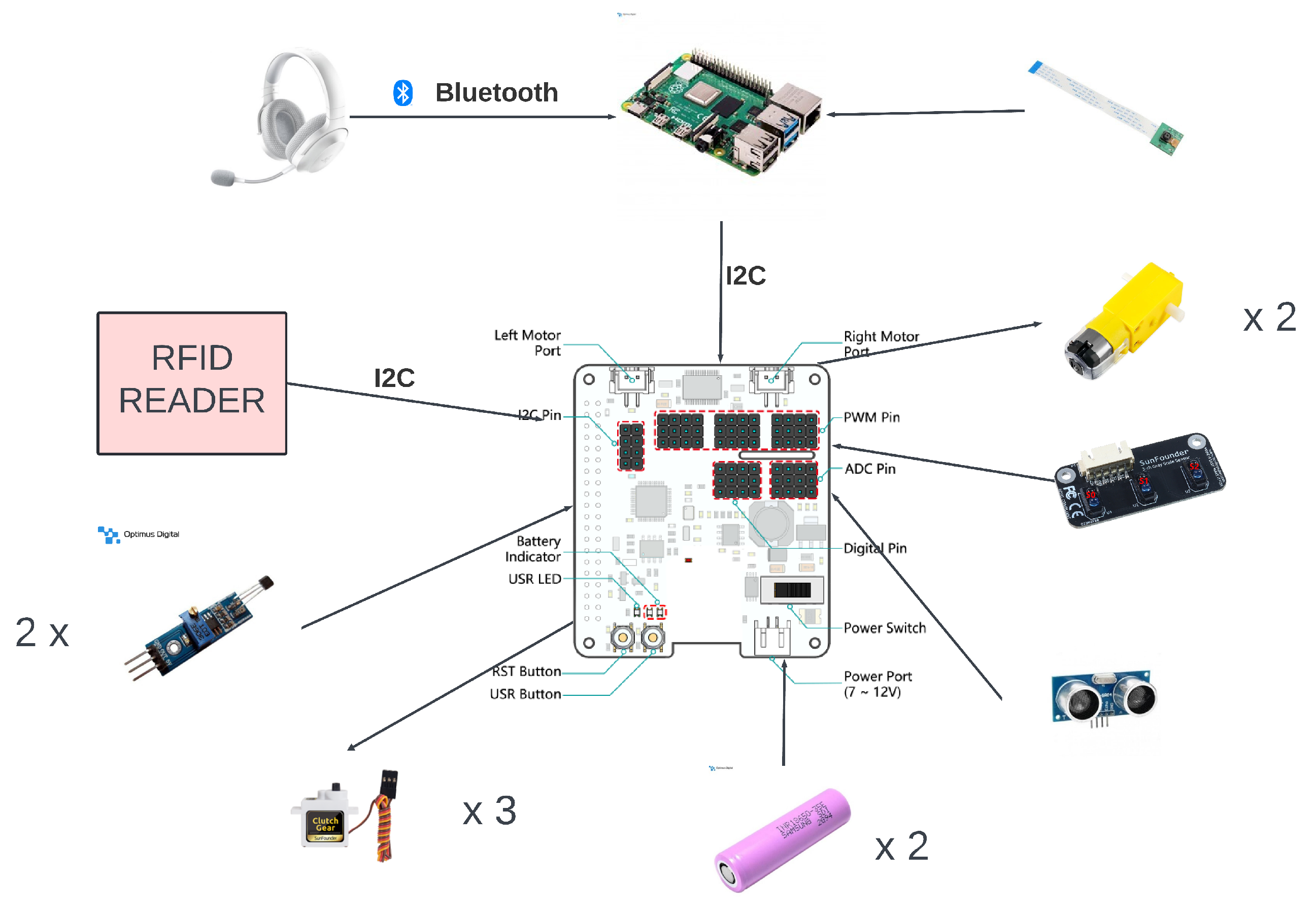
The hardware architecture follows the layered approach presented in the previous section. The first layer, the one that commands and processes all the data, is built around a Raspberry Pi 4, i.e., the central processing element of the system. The second layer, responsible for mobility support, is represented by the SunFounder robot’s hardware at the top (HAT) of Raspberry Pi 4. The HAT plays an intermediary role between the first and last layers, being controlled by the Raspberry Pi and, in turn, controlling the motors and sensors. The last layer is represented by the sensing and action layers. It is the one that interacts with the environment and is composed of ultrasonic detection sensors, a grayscale sensor, two hall sensors, and the headset, but also includes motors, servomotors, and, the most complex piece of this layer, the RFID reader.
Regarding the hardware components of the proposed prototype, we can see the modular approach, as depicted in
Figure 2.
The system has two central control components: the Raspberry Pi and the HAT. Communication between the two is realized through the I2C protocol. I2C also connects the RFID reader to Raspberry Pi. Having I2C as a communication support for both the HAT and the RFID reader, the presented system may be categorized as having a master and two slave devices. Communication between the two slaves is carried out by addressing each of the slaves separately.
Regarding the robotic hardware controlled by Raspberry Pi 4 Model B, we choose the PiCar-X kit from SunFounder, as it includes some of the components necessary for the proposed system, namely a camera, motors and wheels for movement, servomotors for steering and the camera’s two-axis movement, an ultrasonic sensor, a grayscale sensor, and a multifunctional expansion board: the robot HAT. In addition to the components included in the kit, we have also add two Hall effect sensors to monitor the rotation of the rear wheels.
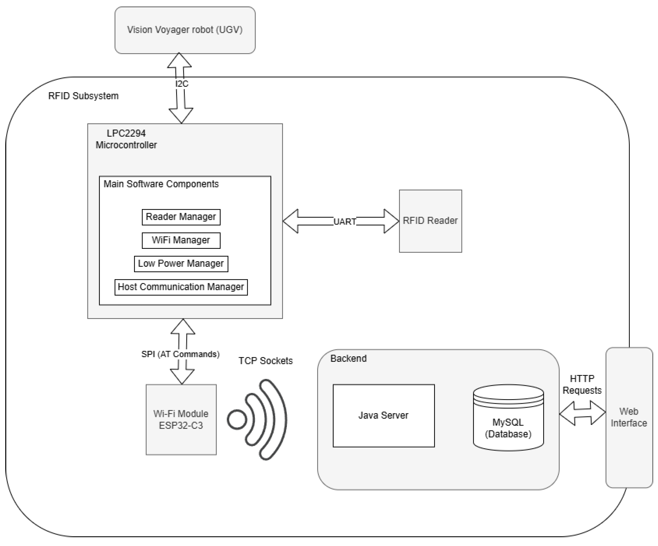
Another important component of the proposed solution is represented by a custom-made RFID subsystem, which is shown in
Figure 3. The subsystem is responsible for detecting the preregistered location passive RFID tags, identifying them, and retrieving the associated information regarding the location from the database. The following main circuits compose the RFID subsystem:
Wi-Fi module: ESP32-C3;
UHF-RFID reader: M6e-Nano;
External antenna;
Microcontroller: Philips LPC2294;
Host system: Raspberry Pi 4.
The UHF-RFID module supports Gen2 UHF passive tags, operating in a range of 865–927 MHz, with a reading range of 30–60 cm with its default antenna. To obtain a reading range of several meters, we configure the reading module and attach an external antenna. Due to the small dimensions of the module we choose a small antenna that operates within the frequency range demanded by the RFID tags and provides a reading range of 2–3 m, which is in agreement with the project’s specifications.
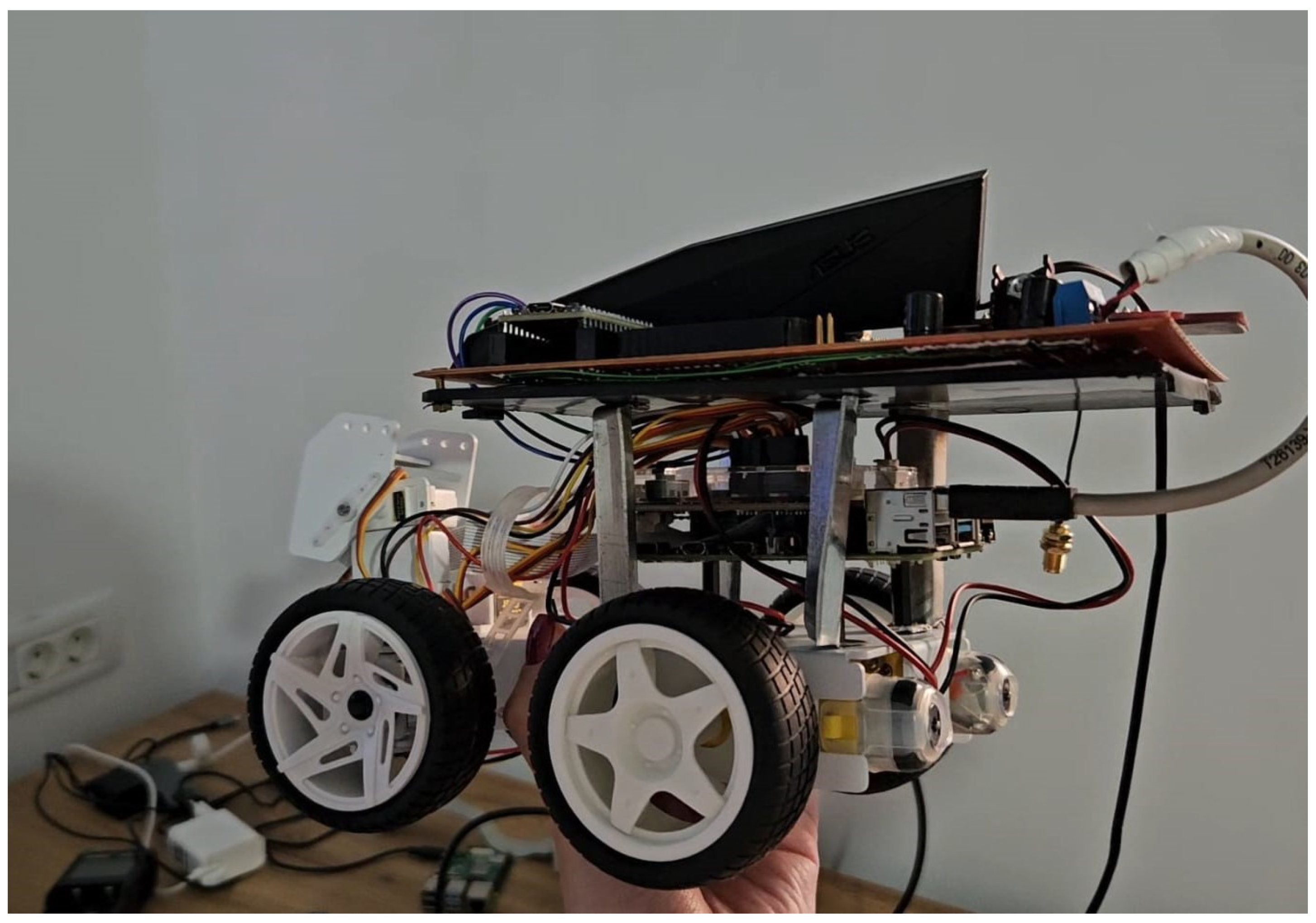
The final prototype is depicted in
Figure 4.
4.3. Methodology
The proposed methodology for Vision Voyager consists of two main steps:
Route registration takes place offline before the beneficiaries actually use the system. It is carried out by an administrator when the building is free (e.g., outside working hours). This recording can be achieved in two different ways, namely by manual recording and a path-following mode, as described in a more detailed manner in the following paragraphs. We choose this approach instead of a fully automated path search because it covers the chosen indoor movement scenarios presented in
Section 3.1. After all, we wish to have control over the routes a visitor should follow in order to avoid possible accidents or crowding paths and areas that are not of direct interest to visually impaired visitors.
The route playback and guiding mode implies the following scenario. Each user will start from an origin location,
, as defined in
Section 3. In each origin location, there will be a prototype of the Vision Voyager robot, with pre-recorded routes from location
to
. Using vocal commands, a user will turn on a robot and choose one location from the options presented by the vocal menu (one option between
–
). The system will play back the routes while vocally guiding the user using repetitive sounds like beacons together with vocal commands (i.e., turn left, go forward, and stop). During route playback and guiding, the system is also responsible for detecting the points of interest and for playing back the information related to each point.
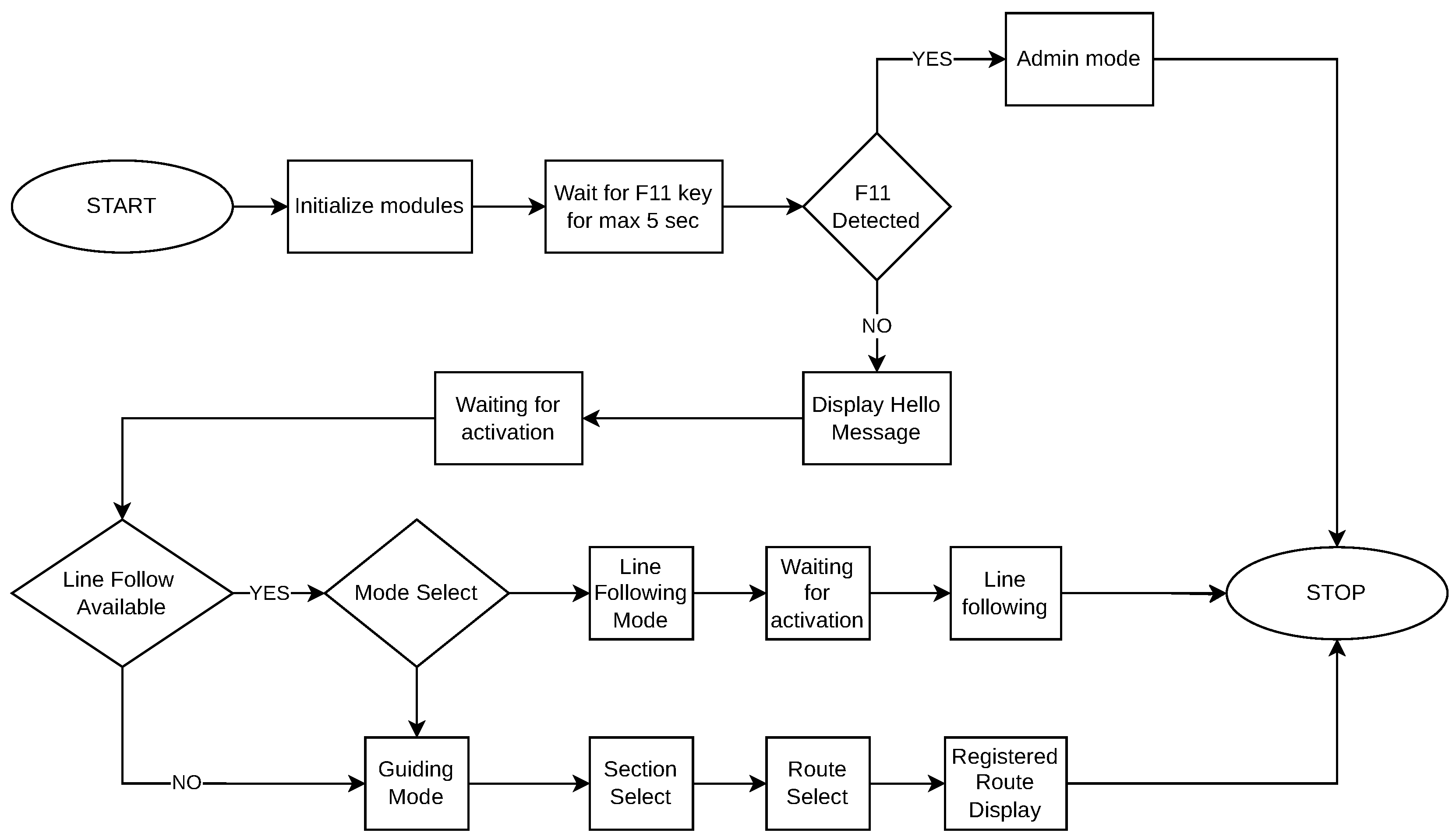
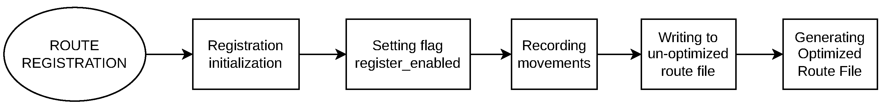
4.3.1. Route Registration and Playback
As mentioned in the previous sections, the system relies on a set of predefined routes. Route recording is responsible for capturing and storing the movements required to follow that fixed route. The process of registering a new route into the menu and recording it is depicted in
Figure 5.
For this process, we implement two alternatives: manual recording and line-following modes. The first corresponds to the RouteManualRecording software module and makes use of the keyboard interface by which an administrator guides the UGV on the chosen path from the origin to the destination point. Each maneuver is then recorded into the text file corresponding to that specific route. Every route has a text file during the recording; thus, adding a new route into the system adds a new file containing the corresponding recording. The second method of recording corresponds to RouteSemiAutomatedRecording; in this case, black tape is stuck to the floor, marking the route between two points of interest. The UGV in the line-following mode follows the tape and records each maneuver into a text file in a similar manner to the previous case with some differences, which will be described in more detail in the next paragraphs.
The process for manual route recording is described in
Figure 6.
Each action is carried out with the support of the modules in
Figure 1, which will be briefly described next. The manual recording is designed to manage input from the administrator via the keyboard and relies on a single external library from IBM called the Curses Library.
Recording a followed line differs from the implementation described in
Figure 6 due to sensor imprecisions; thus, recording the route based on the line requires filtering out the swaying movements over the line and retaining only the direction change movements.
The line-following recording is based on the grayscale hardware module, which consists of three phototransistors. These phototransistors detect differences in light intensity to identify the line’s position and are also used to determine whether the robot is near an edge (e.g., in the proximity of descending stairs). By analyzing the readings from the phototransistors, the module can adjust the robot’s path to maintain a consistent trajectory and ensure safety.
Obstacle avoidance is implemented by the obstacle avoidance module and relies on an ultrasonic sensor. An important note about obstacle avoidance is that it functions both during line following and route guiding.
Managing the robot’s movements is implemented by the VisionVoyagerMoves module, which is also responsible for reading information from its sensors. Its implementation is primarily based on the external library Pybind11, a user-friendly and highly flexible C++ library that allows developers to access functionalities and objects defined in Python (
https://www.python.org/) from C++ and vice versa.
The purpose of this wrapper module is to abstract and facilitate the use of functionalities already provided by the picarx Python library, offered by SunFounder, which manages the movement and reading of hardware elements. It provides a higher level of abstraction, making interaction with the hardware easier without needing to understand all the internal details of the picarx library.
Another module involved in route selection is the VoiceRecognition module. For this module, which is responsible for voice commands, we choose “Pocket Sphinx” as the foundation, a large vocabulary speech recognition engine offered by Carnegie Mellon University in Pittsburgh, Pennsylvania, one of the most popular voice recognition engines compatible with C++, which does not require any Internet connection.
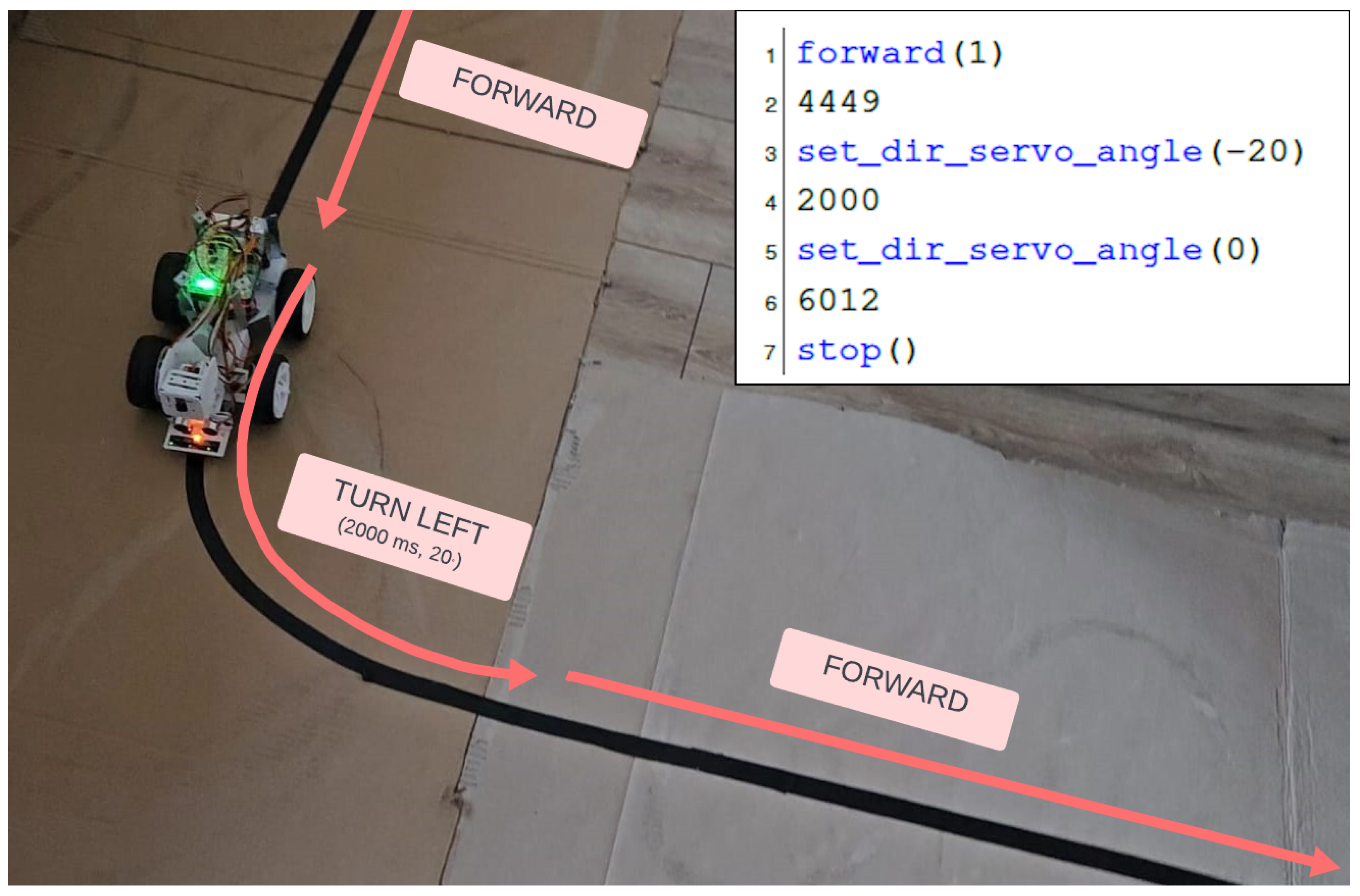
Regarding the recording of a route like the one in
Figure 7, the recording will be stored in the database in a text format, as shown in the upper-right corner.
Here, the command “set_dir_servo_angle(-20)” represents setting the wheel steering direction to the left, while the line following the “set_dir_servo_angle(-20)” command represents maintaining the current command for 2000 ms.
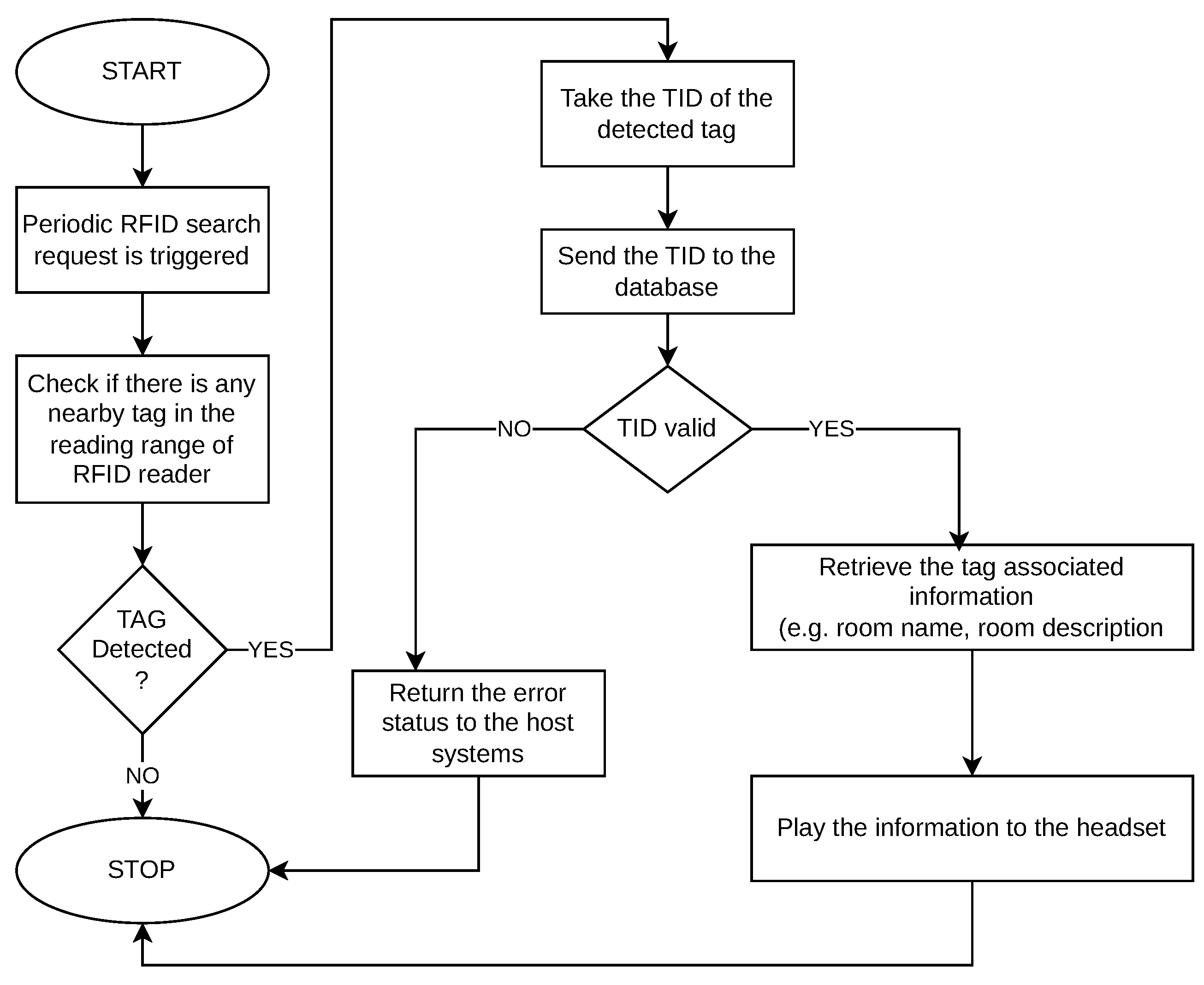
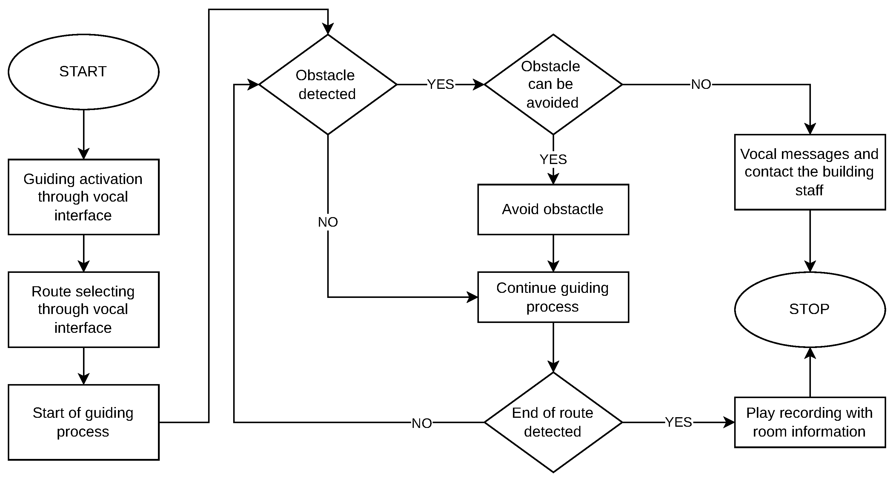
4.3.2. Points of Interest Detection
The detection of predefined locations and points of interest is provided by the UHF-RFID reader module from
Figure 1. While the UGV moves on a pre-recorded route, RFID passive tags of different locations and points of interest enter into the RFID module reading range. When a pre-registered RFID tag is detected, it is searched in the local database, and all the information associated with it is retrieved. With the help of the text to speech module, the text retrieved from the database is transformed into audio format and played in the user headset. This scenario is presented in the UML activity diagram in
Figure 8.
The part responsible for text-to-speech conversion is based on the use of eSpeak software (
https://espeak.sourceforge.net/), an open-source, compact software known for its space efficiency, making it suitable for inclusion in resource-limited systems.
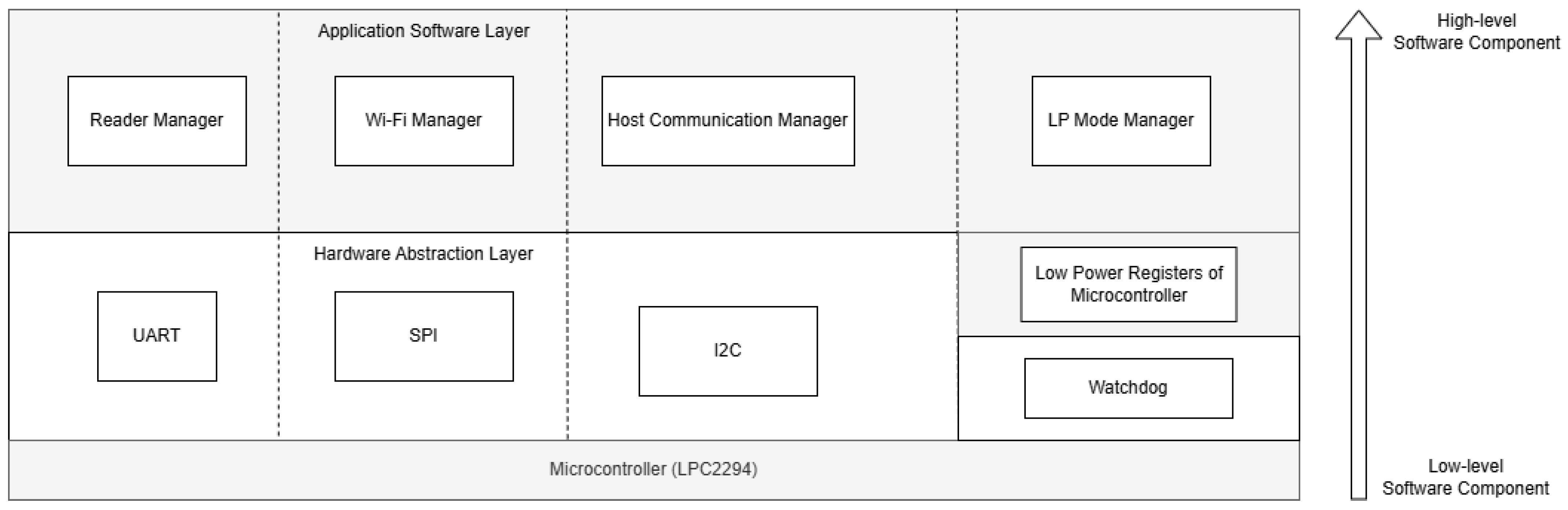
The RFID module, running on the microcontroller, implements the “Superloop” concept and is divided into four software components, each of them being responsible for handling a hardware resource (e.g., UART and I2C). The software components depicted in
Figure 9 and defined at the subsystem level are as follows:
The RFID reader finds a nearby passive tag and sends the TID (Tag ID) to the database. A TID is associated with the following information: room name, room description, and a boolean stating if the room is a terminal node in the route to which it belongs. All that information is given to the UGV device as text, which can be further processed through a text-to-speech mechanism.
On a more detailed level, the implemented commands for the RFID subsystem are as follows:
Search for new nearby rooms;
Check if the subsystem is initialized;
Send a ping signal to the subsystem.
Once an external request for detecting new nearby rooms is made by the UGV host system, the software component “Host Communication Manager” is woken up. This component is responsible for the handling of communication with the external environment. While a request is in progress on the RFID subsystem’s side, a “REQUEST PENDING” is sent as a response until a final acceptance or decline of the request is concluded and acknowledged by the host system.
The component “Low Power Mode Manager” is responsible for putting the whole microcontroller-based system into sleep mode to improve power consumption. If at least one software component has a job to process, the whole system will stay awake. If all components are finished with their jobs, the microcontroller will enter sleep mode.
“Reader Manager” is responsible for commanding the hardware RFID reader and communicating with the “Wi-Fi Manager”, which acts as a bridge between the microcontroller and the remote database. The communication between the microcontroller and the database is carried out using sockets, and no actual Internet connection is required.
Recovery algorithms are also implemented in case the communication between any of the hardware modules fails. If the communication cannot be recovered, the whole subsystem enters a “safe state”, where new requests will automatically be declined. Watchdog protection is implemented and well-integrated with the sleep mode.
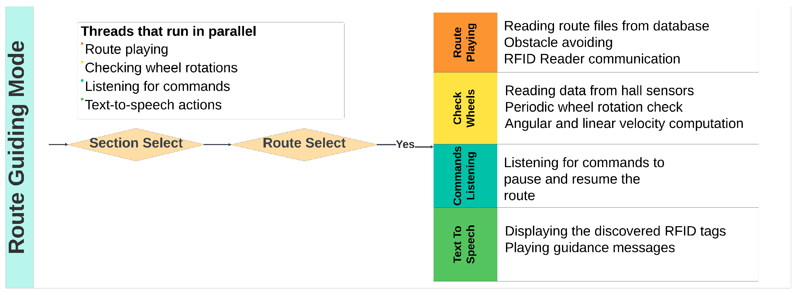
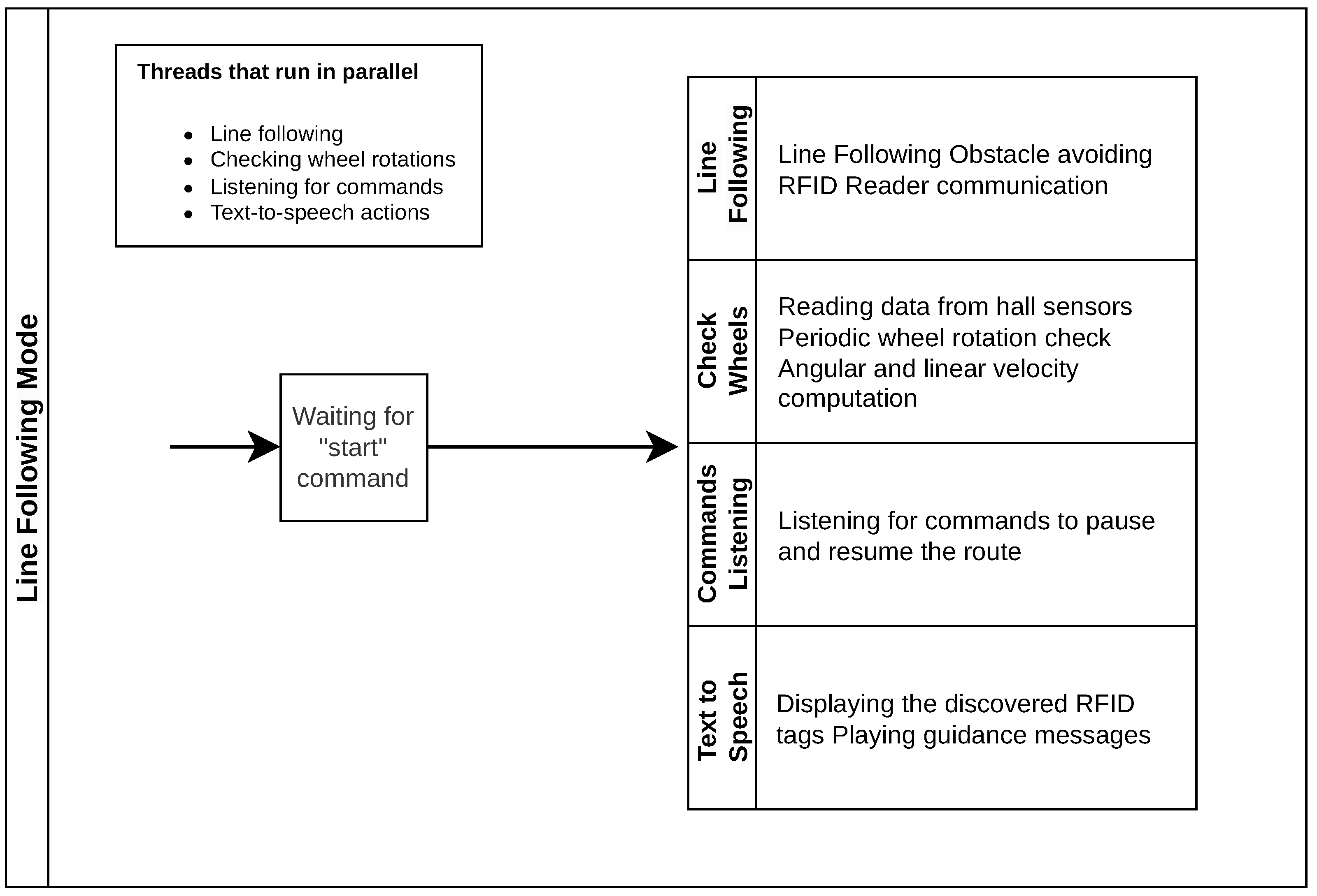
5. Testing Hypotheses and Experiments
To test, validate, and measure the performance of the proposed system, we chose two operation modes: the “Route-Guiding Mode” (
Figure 12), where the robot can playback pre-recorded routes, and “Line-Following Mode” (
Figure 13), where the robot follows a line and, based on the directions of the line, guides a visually impaired person along a path. The experiments were designed to measure the system’s performance under different conditions and to evaluate its accuracy. The performance metrics used were accuracy regarding the guiding instructions, object detection and voice recognition, and precision regarding the path following expressed in terms of trajectory deviation.
Depending on the two modes of operation, the robot performs a multitude of actions, many of which run in parallel using threading. Numerous tests have been conducted on the system, ranging from basic feature tests like text-to-speech, voice recognition, or line following to more complex guidance scenarios where the robot records and executes a route.
5.4. Results
The usability test that we considered at the system level was regarding the accuracy and voice command clarity. The testing scenario consisted of navigation from a predefined origin point (e.g., building entrance) to a user-selected room, following the audio instructions. We focused on verifying that the order and timing of the guidance commands were properly synchronized to ensure the user was directed to the chosen destination. The success criteria for this topic include the following aspect: correct synchronization of guidance commands. This criterion can be divided into two smaller, measurable criteria: validity of the guidance message and Guidance message timing. In terms of the validity of the messages, we refer to the correct order of movements, which must be accurate in every case, even when the robot is required to deviate from the planned route to avoid an obstacle. The second criterion, the timing of when a guidance message is provided to the user, is subject to error, as there may be slight disruptions caused by factors such as the speed at which the robot’s wheels rotate on different surfaces.
To assess overall performance, we consolidated the data obtained from all the tests conducted in
Table 2.
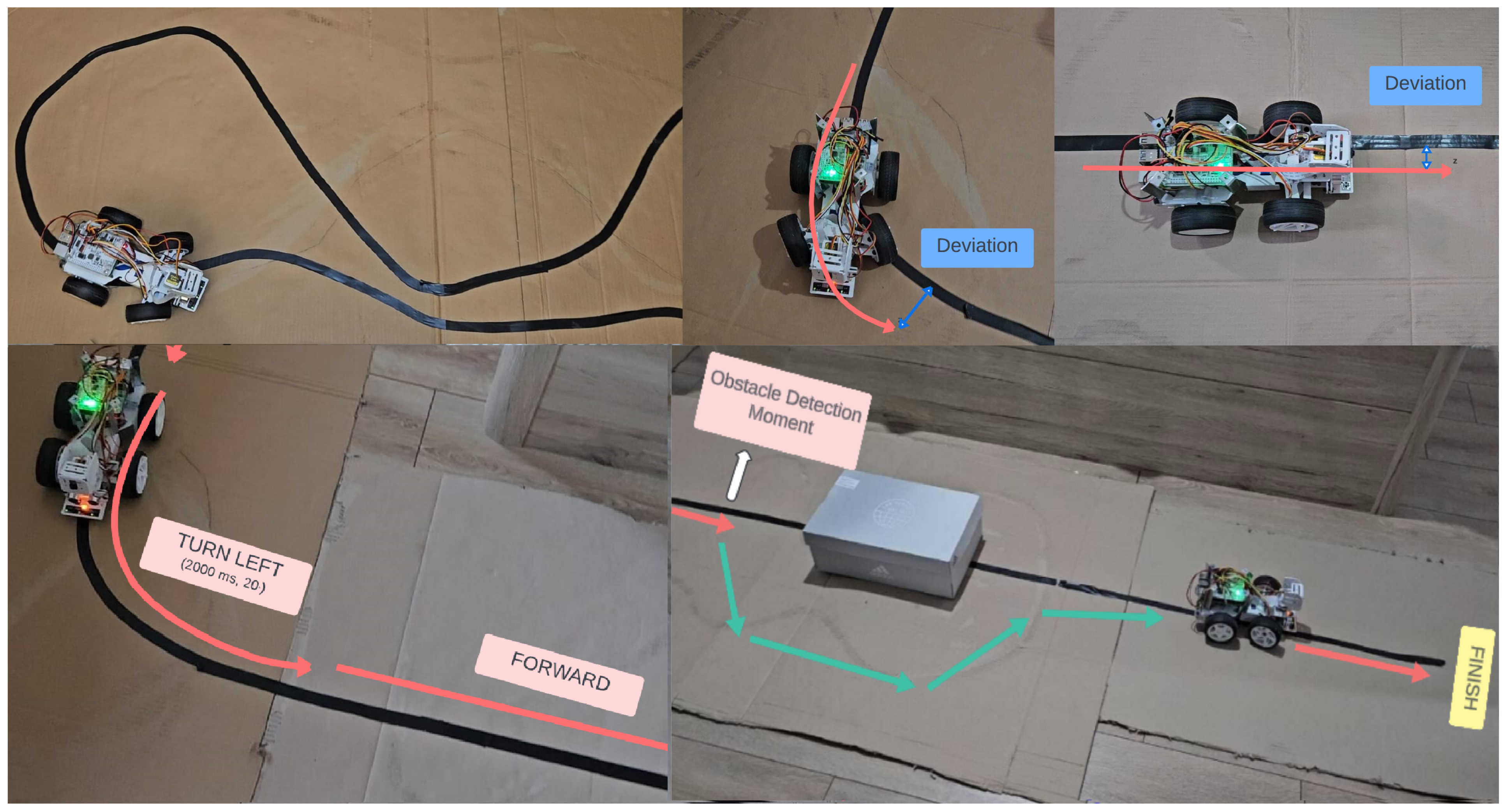
The route recording covered the two different modes proposed in this paper: the manual mode, obtaining deviation < 2%, and the line-following mode, with a slightly higher deviation. This deviation means that during route playback, the robot reached a position between 2% and 7%, respectively, of the total route length away from the exact spot where it stopped during recording.
The validity of the guidance message test verified the accuracy of recording and playback of the command sequence, with 100% meaning that all the commands recorded and played for the user were valid. The guidance message timing test refers to the timing of the commands given to the user for navigation, where 5–10% deviation indicates that the commands are delivered 5% to 10% earlier or later than planned due to delays or variations in how the processing threads are executed.
The line-following accuracy tests show that during line following, the robot never loses the line.
The wheel rotation problem detection accuracy test shows that the robot always detects if one of the rear wheels stops or rotates slower than planned. In contrast, the edge detection accuracy test shows that the robot detects all instances when it reaches an edge, such as a staircase or a change in elevation.
The obstacle detection tests show that the robot detects obstacles most of the time, but occasionally (in less than 5% of cases), it detects them too late to react in time due to how the threads interact. Meanwhile, an obstacle-avoiding accuracy > 60% means that in at least two out of three cases, the robot successfully avoids the obstacle. However, sometimes, it gets stuck by detecting a new obstacle, for example, when it is too close to a wall while performing the avoidance manoeuvre. The deviation refers to being 5% to 10% further than the point where the robot would have reached if there were no obstacles. The deviation and failure to avoid the obstacle also occur due to the robot’s position and angle after the maneuver, which can block the path.
A voice recognition accuracy > 75% shows the robot’s capacity to recognize the given command. A deviation < 10% refers to the fact that in 1 out of 10 cases, the robot recognizes a different command than the one spoken. Occasionally, the robot does not recognize anything at all, and the recognition process is restarted.
RFID Subsystem Testing
Regarding the RFID subsystem, two different parameters were measured and analyzed in order to evaluate its performance: detection time and energy consumption.
By default, the RFID subsystem request to start RF emissions would lead to continuous (in “burst”) RF emissions. Although this guarantees faster detection times for passive tags, this also leads to over-temperature conditions.
The RFID module supports configurations (via UART) for two RF parameters:
RF on time, which tells us how long the RFID emits RF.
RF off time, which tells us how long RF emissions shall pause after one emission round.
The RFID subsystem supports parametrization for the total search time, which can be configured at compile-time. In the following section, we will discuss how “RF on time” and “RF off time” described above and the requested search time are related to each other.
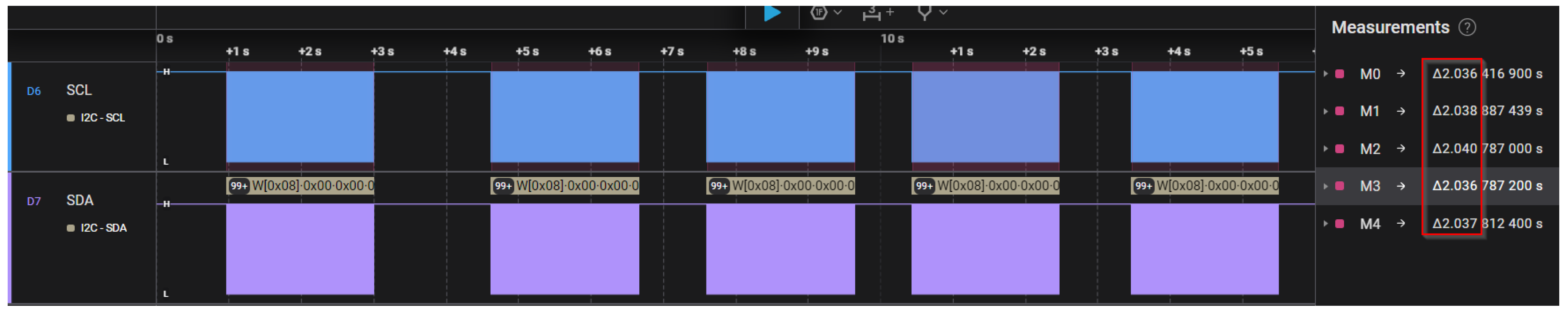
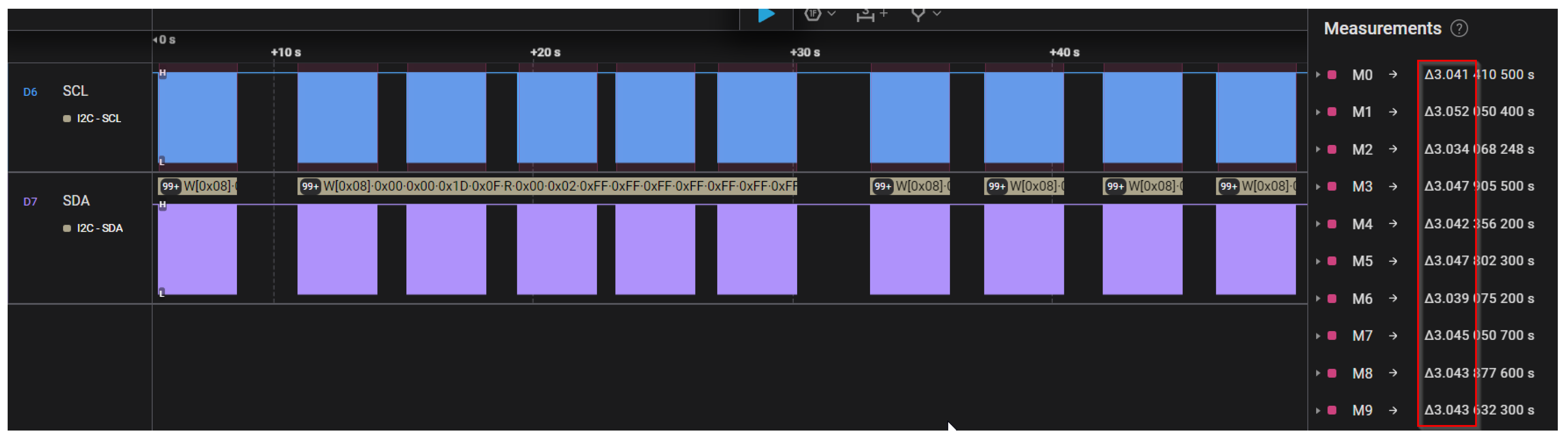
In
Figure 15 and
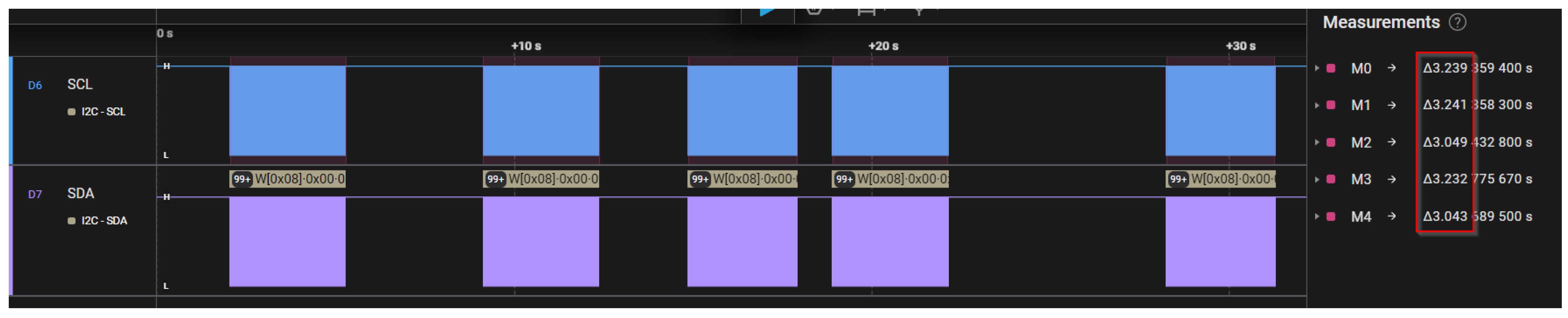
Figure 16, the expected search time was set to 2 s and 3 s, while “RF on time” and “RF off time” parameters were set to 500 ms in both cases. In the mentioned figures, it can be observed that the actual search time is quite accurate with the expected value, in contrast with the scenario depicted in
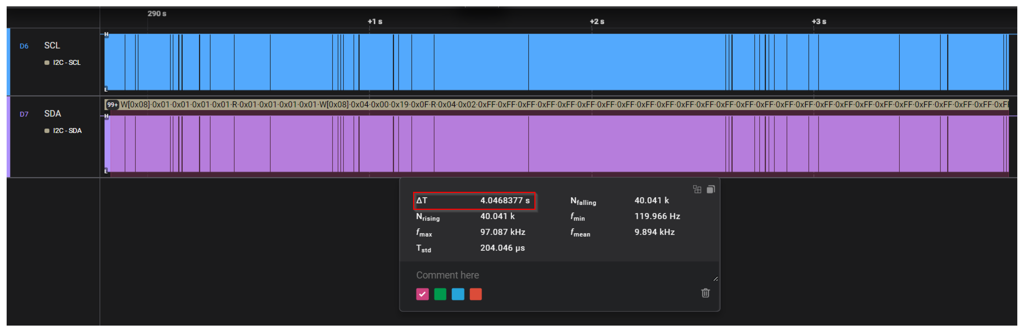
Figure 17. In this case, the expected search time remains unchanged, but “RF on time” is increased to 700 ms while “RF off time” is increased to 900 ms. An increased deviation can be observed in the latter case. The deviation is greatly further increased in
Figure 18 when both RF times are set to 1000 ms.
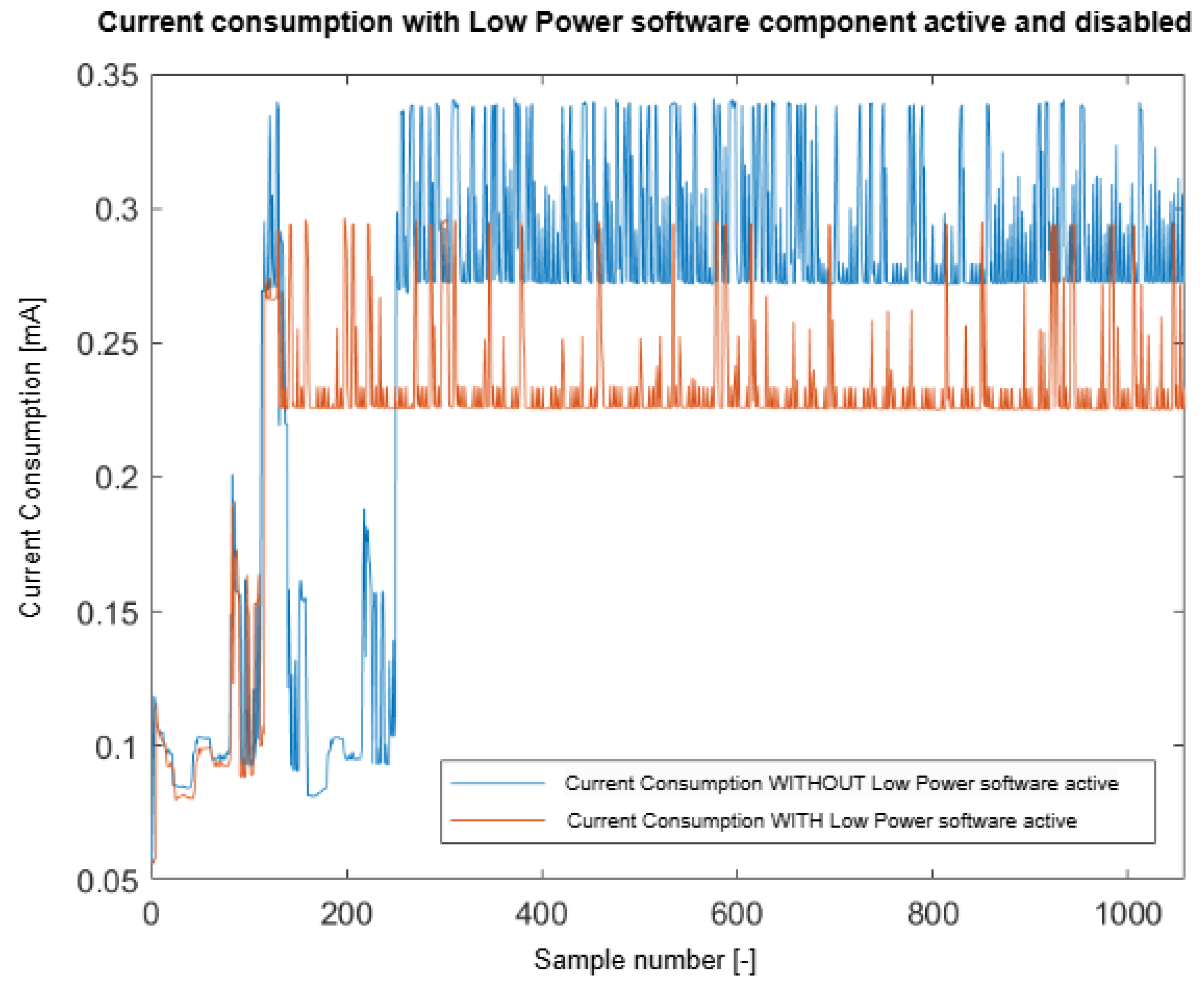
Regarding the RFID subsystem, the current consumption was measured in isolation to other subsystems in two scenarios:
In
Figure 19, the current consumption results are presented. It can be observed that there is a slight improvement regarding power consumption when the Low-Power Mode Manager component is enabled, even if the “Low-Power” mode implementation targets only the microcontroller, which enters sleep mode when there is no external request to be performed. This means the RFID and Wi-Fi modules are still awake, running their internal algorithms. In the mentioned diagram, this behavior can be easily noticed by observing the periodic spikes in the measurements (in both cases).
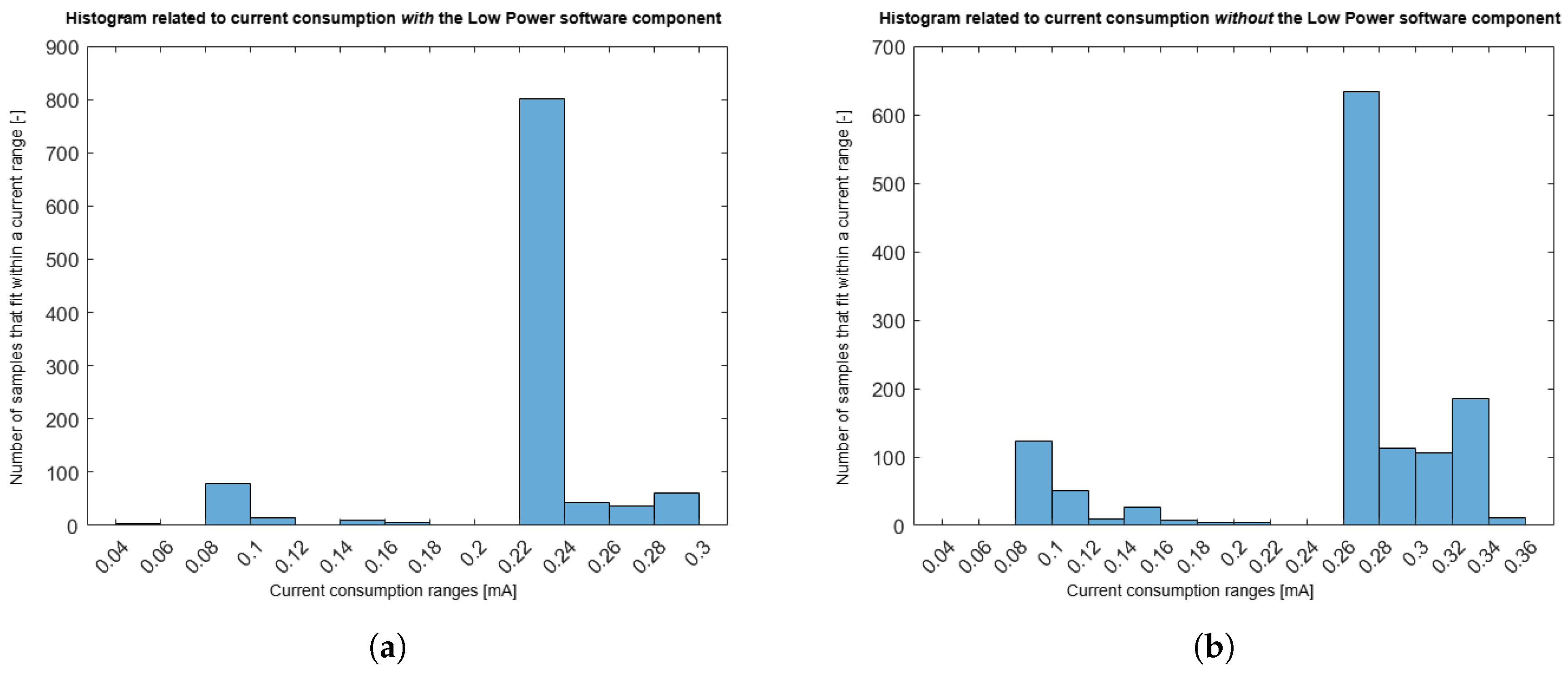
The distribution of the current consumption measurements can also be visualized in
Figure 20.


 ,
, 


